EP4576518A1 - Motorkühlungsstruktur - Google Patents
Motorkühlungsstruktur Download PDFInfo
- Publication number
- EP4576518A1 EP4576518A1 EP23885431.9A EP23885431A EP4576518A1 EP 4576518 A1 EP4576518 A1 EP 4576518A1 EP 23885431 A EP23885431 A EP 23885431A EP 4576518 A1 EP4576518 A1 EP 4576518A1
- Authority
- EP
- European Patent Office
- Prior art keywords
- cooling medium
- welding
- coil end
- discharge hole
- supply portion
- Prior art date
- Legal status (The legal status is an assumption and is not a legal conclusion. Google has not performed a legal analysis and makes no representation as to the accuracy of the status listed.)
- Pending
Links
Images


Classifications
-
- H—ELECTRICITY
- H02—GENERATION; CONVERSION OR DISTRIBUTION OF ELECTRIC POWER
- H02K—DYNAMO-ELECTRIC MACHINES
- H02K3/00—Details of windings
- H02K3/04—Windings characterised by the conductor shape, form or construction, e.g. with bar conductors
- H02K3/24—Windings characterised by the conductor shape, form or construction, e.g. with bar conductors with channels or ducts for cooling medium between the conductors
-
- H—ELECTRICITY
- H02—GENERATION; CONVERSION OR DISTRIBUTION OF ELECTRIC POWER
- H02K—DYNAMO-ELECTRIC MACHINES
- H02K9/00—Arrangements for cooling or ventilating
- H02K9/19—Arrangements for cooling or ventilating for machines with closed casing and closed-circuit cooling using a liquid cooling medium, e.g. oil
Definitions
- the present invention relates to a motor cooling structure.
- Patent Literature 1 discloses a cooling device in which discharge holes for a cooling medium are provided on respective upstream sides offset from the respective centers of coil end parts by a distance a.
- this cooling device when the flow rate of the cooling medium is small, the cooling medium is discharged directly below, that is, to the upstream side offset from the center of each coil end part by the distance a, and when the flow rate of the cooling medium is maximum, the cooling medium is discharged to the center of each coil end part.
- oil coverage rate in the coil end part can be maximized when the flow rate of the cooling medium is maximum, and as a result, the maximum cooling effect can be obtained when coolness is most required.
- Patent Literature 1 JP 2006-115652 A
- coil shapes in the two coil end parts provided in annular shapes are different, and the sizes of the coil end parts are different. That is, the coils are curved in one of the coil end parts, and the coils are welded in the other one of the coil end parts. In the coil end part where the coils are welded, because of welding, an interval between the coils is larger than the interval between the coils in the coil end part where the coils are curved. Thus, regarding the sizes of the coil end parts in a radial direction, the coil end part where the coils are welded is larger than the coil end part where the coils are curved.
- the present invention has been made in view of the above problems, and the present invention secures a range covered with a cooling medium and enhances coolness by causing the cooling medium to land at each of respective proper positions for two coil end parts having different shapes and sizes.
- a motor cooling structure configured to cool a motor including a stator core on which a plurality of coils are wound, the motor including two coil end parts protruding from both end portions in an axial direction of the stator core, the motor cooling structure including: a first cooling medium pipe configured to supply a cooling medium to one of the two coil end parts; and a second cooling medium pipe configured to supply a cooling medium to another one of the two coil end parts, in which the first cooling medium pipe includes a first cooling medium supply portion overlapping a corresponding one of the coil end parts along the axial direction, the second cooling medium pipe includes a second cooling medium supply portion overlapping a corresponding one of the coil end parts along the axial direction, the first cooling medium supply portion and the second cooling medium supply portion are formed with respective discharge holes each configured to discharge a cooling medium to a corresponding one of the coil end parts, and respective positions of the first cooling medium supply portion and the second cooling medium supply portion in a gravity direction are different from each other.
- the positions of the two cooling medium distribution and supply portions in the gravity direction are different from each other.
- flexibility is increased in positional adjustment of each cooling medium pipe, and the cooling medium is caused to land at each of respective proper positions for the coil end parts, which are the two coil end parts having different shapes and sizes, whereby a range covered with the cooling medium can be secured and coolness can be enhanced.
- FIG. 1 is a side view showing a motor 1 and a motor cooling device 2 according to the present embodiment.
- the motor cooling device 2 includes a rotor (not shown), a stator 10, a welding-side coil end part 21, and a counter-welding-side coil end part 22.
- the motor cooling device 2 includes a motor cooling structure.
- an axial direction A is a direction parallel to a rotation axis (central axis) O of the stator 10.
- a first axial direction When two directions in the axial direction A are distinguished, one of the two directions is referred to as a first axial direction, and the other one of the two directions is referred to as a second axial direction.
- a first axial direction A1 that is, the counter-welding-side coil end part side
- a second axial direction A2 the left direction in the paper surface of FIG. 1 , that is, the welding-side coil end part side
- a circumferential direction about the central axis O of the stator 10 is referred to as a circumferential direction R.
- a radial direction about the central axis O of the stator 10 is referred to as a radial direction.
- a gravity direction H is a gravity direction in a state where the motor 1 is mounted in a vehicle.
- a direction opposite to the gravity direction H is referred to as a height direction.
- the stator 10 is formed in an annular shape, and is installed such that the axial direction A thereof is orthogonal to the gravity direction H.
- the stator 10 includes a stator core 11 and coils 12 wound on the stator core 11.
- a plurality of slots (not shown) are disposed at equal intervals along the circumferential direction R.
- Each of the coils 12 is inserted into a corresponding one of the plurality of slots.
- the coils 12 protrude from both ends of the stator core 11 in the axial direction A, and form the two coil end parts (the welding-side coil end part 21 and the counter-welding-side coil end part 22).
- Each of the two coil end parts is formed in an annular shape (doughnut shape) as viewed in the axial direction A.
- Each of the coils 12 is wound on the stator core 11 to have an inclined portion, which extends in the circumferential direction of the stator 10 while changing in height in the axial direction A. Moreover, in one of the coil end parts, the coils 12 are curved by bending, and in the other one of the coil end parts, tips of the coils 12 are electrically connected to each other by welding.
- laser welding using a laser beam, or tungsten inert gas (Tig) welding which is a type of arc welding, is preferably used.
- the coil end part on the welding side is referred to as the welding-side coil end part 21, and the coil end part on the side curved by bending, that is, the coil end part on the side opposite to the welding side is referred to as the counter-welding-side coil end part 22.
- an end portion on which the welding-side coil end part 21 is formed is referred to as a welding-side end portion 101
- an end portion on which the counter-welding-side coil end part 22 is formed is referred to as a counter-welding-side end portion 102.
- the diameter size of the annular ring of the welding-side coil end part 21 is larger than the diameter size of the annular ring of the counter-welding-side coil end part 22. Therefore, in the height direction, the highest position H12 of the counter-welding-side coil end part 22 is lower than the highest position H11 of the welding-side coil end part 21. In this manner, the coil shapes and the diameter sizes are different between the welding-side coil end part 21 and the counter-welding-side coil end part 22.
- the diameter size is a size in a radial direction about the central axis of the annular ring of the welding-side coil end part 21.
- each of the central axis of the annular ring of the welding-side coil end part 21, the central axis of the annular ring of the counter-welding-side coil end part 22, and the central axis of the stator core 11 coincides with the central axis of the stator 10.
- the coil 12 is insulated by being subjected to enameled coating, but a welded portion is not subjected to enameled insulation. Such a portion not subjected to enameled insulation is insulated by being coated with insulating material (varnish, resin, or the like) other than enamel.
- insulating material varnish, resin, or the like
- coils in a range from an end portion 211 of the welding-side coil end part 21 to a boundary position J are an insulated portion 214 insulated with insulating material.
- the illustration of the insulated portion 214 is omitted, and the welding-side coil end part 21 is shown.
- the boundary position J is a boundary position between the insulated portion 214 insulated with insulating material and a portion not insulated with the insulated portion 214 in the welding-side coil end part 21.
- the motor cooling device 2 includes a first cooling medium pipe 31 and a second cooling medium pipe 32.
- the first cooling medium pipe 31 supplies a cooling medium to the welding-side coil end part 21.
- the second cooling medium pipe 32 supplies the cooling medium to the counter-welding-side coil end part 22.
- the first cooling medium pipe 31 and the second cooling medium pipe 32 are two cooling medium pipes branching from a cooling medium supply path.
- the cooling medium is a liquid cooling medium for cooling the motor, and cools, for example, the welding-side coil end part 21 and the counter-welding-side coil end part 22.
- the cooling medium for example, cooling oil is used.
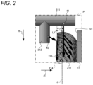
- FIG. 2 is an enlarged view of a region P shown in FIG. 1 .
- FIG. 3 is a view of the region P as viewed from behind toward front of the paper surface of FIG. 1 .
- FIG. 4 is a view of the region P shown in FIG. 1 , as viewed in the first axial direction A1.
- FIG. 5 is a cross-sectional view taken along line B-B shown in FIG. 4 , and is a view of the region P as viewed from an upper side along the gravity direction H.
- a vertical plane K parallel to the gravity direction H and including the central axis O of the stator 10 is defined as a boundary position, and in the welding-side coil end part 21 shown in FIG.
- first welding-side region one region divided at the boundary position is referred to as a first welding-side region, and the other divided region is referred to as a second welding-side region.
- first welding-side region 212 the right side and the left side in the paper surface of FIG. 4 are referred to as a first welding-side region 212 and a second welding-side region 213, respectively.
- a lateral direction in the paper surface of FIG. 4 that is, a horizontal direction perpendicular to both the gravity direction H and the axial direction A is referred to as a horizontal direction C.
- the horizontal direction C one direction is referred to as a first horizontal direction, and the other direction is referred to as a second horizontal direction.
- the right direction in the paper surface of FIG. 4 is referred to as a first horizontal direction C1
- the left direction is referred to as a second horizontal direction C2.
- the circumferential direction R one direction is referred to as a first circumferential direction, and the other direction is referred to as a second circumferential direction.
- the first cooling medium supply portion 311 is provided with a first welding-side discharge hole 41 and a second welding-side discharge hole 42. As shown in FIG.
- the position of the first welding-side discharge hole 41 in the axial direction A is a position between the boundary position J and the welding-side end portion 101 of the stator core 11 and close to the boundary position J.
- the position of the second welding-side discharge hole 42 in the axial direction A is a position between the boundary position J and the welding-side end portion 101 of the stator core 11 and close to the boundary position J.
- the position of the second welding-side discharge hole 42 in the axial direction A is close to the welding-side end portion 101 of the stator core 11. In this manner, the positions of the first welding-side discharge hole 41 and the second welding-side discharge hole 42 in the axial direction A are different from each other.
- the first welding-side discharge hole 41 is provided to discharge the cooling medium along the first circumferential direction R1 of the welding-side coil end part 21.
- the first welding-side discharge hole 41 is formed to face the first welding-side region 212 side, and is formed such that the axis of the first welding-side discharge hole 41 coincides with a radial direction of the cylinder of the first cooling medium pipe 31.
- the radial direction of the cylinder is a radial direction about the central axis of the cylinder of the first cooling medium pipe 31.
- the cooling medium lands on the welding-side coil end part 21 along the first circumferential direction R1, and flows in the gravity direction H along the inclinations of the coils 12 in the welding-side coil end part 21.
- the second welding-side discharge hole 42 is provided to discharge the cooling medium along the second circumferential direction R2 of the welding-side coil end part 21.
- the second welding-side discharge hole 42 is formed to face the second welding-side region 213, and is formed such that the axis of the second welding-side discharge hole 42 coincides with the radial direction of the cylinder of the first cooling medium pipe 31.
- the cooling medium lands on the welding-side coil end part 21 along the second circumferential direction R2, and flows in the gravity direction H along the inclinations of the coils 12 in the welding-side coil end part 21.
- the first welding-side discharge hole 41 is disposed at a position close to the end portion 211 of the welding-side coil end part 21, as compared with the second welding-side discharge hole 42. More specifically, a distance L1 (see FIG. 2 ) in the axial direction A between the first welding-side discharge hole 41 and the end portion 211 is shorter than a distance L2 (see FIG. 3 ) in the axial direction A between the second welding-side discharge hole 42 and the end portion 211.
- each of the tips of the coils 12 extending from the slots is inclined for welding, and the direction of this inclination is different on both sides in the circumferential direction R of the welding-side coil end part 21.
- the coil is wound to be directed toward the gravity direction H while being directed toward the first axial direction A1.
- the first welding-side discharge hole 41 is disposed at a position substantially identical to the boundary position J, in the axial direction A. Accordingly, the cooling medium having landed on the first welding-side region 212 of the welding-side coil end part 21 flows toward the gravity direction H while being toward the first axial direction A1.
- a wide range of the welding-side coil end part 21 can be covered with the cooling medium, and cooling performance can be enhanced
- the coil 12 is wound to be directed toward the gravity direction H while being directed toward the second axial direction A2.
- the cooling medium is unable to be caused to flow toward the stator core 11 side. Therefore, in the present embodiment, the second welding-side discharge hole 42 is disposed close to the stator core 11 side with respect to the boundary position J, in the axial direction A.
- the cooling medium having landed on the second welding-side region 213 of the welding-side coil end part 21 flows toward the gravity direction H while being toward the second axial direction A2. Therefore, a wide range of the welding-side coil end part 21 can be covered with the cooling medium, and cooling performance can be enhanced.
- each of the first welding-side discharge hole 41 and the second welding-side discharge hole 42 is disposed at such a position where the cooling medium lands at a high position in the height direction, in an inclination direction in which the coil is wound. Therefore, a wide range of the welding-side coil end part 21 and a wide range of the counter-welding-side coil end part 22 can be covered with the cooling medium discharged from the first welding-side discharge hole 41 and the second welding-side discharge hole 42, respectively.
- the first cooling medium pipe 31 is formed with a third cooling medium supply portion 312 branching from the first cooling medium supply portion 311 and extending toward an inner side in the radial direction (an inner diameter side) of the stator core 11.
- the radial direction of the stator core 11 is identical to the radial direction of the stator 10, and the inner side in the radial direction is a direction toward the central axis O of the stator 10.
- the third cooling medium supply portion 312 extends in the gravity direction H at a position facing the end portion 211 of the welding-side coil end part 21.
- the third cooling medium supply portion 312 is provided with a third welding-side discharge hole 43 and a fourth welding-side discharge hole 44.
- the third welding-side discharge hole 43 and the fourth welding-side discharge hole 44 discharge, to the welding-side coil end part 21 that the third welding-side discharge hole 43 and the fourth welding-side discharge hole 44 face in the axial direction A, the cooling medium, toward the one side and the other side in the circumferential direction of the welding-side coil end part 21, that is, the first welding-side region 212 and the second welding-side region 213.
- the third welding-side discharge hole 43 is formed to face the first welding-side region 212, and is formed such that the axis of the third welding-side discharge hole 43 coincides with a radial direction of the cylinder of the third cooling medium supply portion 312.
- the radial direction of the cylinder is a radial direction about the central axis of the cylinder.
- the third welding-side discharge hole 43 is formed such that the axis thereof is angled toward the first horizontal direction C1 with respect to the axial direction A, that is, angled toward the first welding-side region 212 side.
- the cooling medium is discharged in a direction angled toward the first horizontal direction C1 with respect to the first axial direction A1.
- the cooling medium flows while being angled in the gravity direction H due to gravity.
- the fourth welding-side discharge hole 44 is formed such the axis thereof is angled toward the second horizontal direction C2 with respect to the first axial direction A1, that is, angled toward the second welding-side region 213 side.
- the cooling medium is discharged in a direction angled toward the second horizontal direction C2 with respect the first axial direction A1.
- the cooling medium flows while being angled in the gravity direction H due to gravity.
- an angle formed between the direction of the cooling medium discharged from the third welding-side discharge hole 43 and the direction of the cooling medium discharged from the fourth welding-side discharge hole 44 is preferably less than 90°, and more preferably 20° to 60°.
- the cooling medium can be reliably discharged to the welding-side coil end part 21. Therefore, by allowing the cooling medium to flow on axial end portions on both sides in the circumferential direction of the welding-side coil end part 21, cooling performance in the welding-side coil end part 21 can be enhanced.
- the cooling medium is discharged from the third cooling medium supply portion 312 along the first axial direction A1
- the cooling medium is repelled at the end portion 211 of the welding-side coil end part 21, and a wide range cannot be covered.
- the motor cooling device 2 of the present embodiment instead of discharging the cooling medium from the third cooling medium supply portion 312 along the first axial direction A1, the motor cooling device 2 of the present embodiment discharges the cooling medium while angling the cooling medium toward the horizontal direction with respect to the first axial direction A1.
- the cooling medium discharged from each of the third welding-side discharge hole 43 and the fourth welding-side discharge hole 44 lands on the end portion 211 of the welding-side coil end part 21 in a direction of flow along the circumferential direction of the welding-side coil end part 21.
- the cooling medium is hardly repelled at the end portion 211. Further, the cooling medium having landed on the end portion 211 flows in the gravity direction H while being along the direction of the inclined portions of the coils, that is, along the axial direction A and the circumferential direction R, whereby the coils can be covered in a wide range.
- each of the third welding-side discharge hole 43 and the fourth welding-side discharge hole 44 is simply required to discharge the cooling medium in a direction angled with respect to the first axial direction A1, and the angled direction is not limited to the horizontal direction.
- each of the respective directions in which the cooling medium is discharged from the third welding-side discharge hole 43 and the fourth welding-side discharge hole 44 may be a direction angled toward the gravity direction H or a direction angled toward a direction opposite to the gravity direction H. In either case, the cooling medium can be made less likely to be repelled.
- each of the respective positions of the third welding-side discharge hole 43 and the fourth welding-side discharge hole 44 in the gravity direction H is preferably a position of between four-tenths and six-tenths of a width in a radial direction of the annular ring of the welding-side coil end part 21.
- the cooling medium is discharged above the welding-side coil end part 21 in the horizontal direction C, and the cooling medium cannot be efficiently discharged to the welding-side coil end part 21.
- the third welding-side discharge hole 43 and the fourth welding-side discharge hole 44 are preferably disposed at proper positions not so high as to exceed the welding-side coil end part 21.
- the cooling medium can be caused to land at a proper position for the welding-side coil end part 21, a covered range on which the cooling medium flows can be secured in the welding-side coil end part, and cooling performance can be enhanced.
- the second cooling medium pipe 32 provided for the counter-welding-side coil end part 22 will be described.
- the welding-side coil end part 21 and the counter-welding-side coil end part 22 have different diameter sizes, different heights, different coil inclination directions, and different coil densities.
- the motor cooling device 2 of the present embodiment discharges the cooling medium to the welding-side coil end part 21 and the counter-welding-side coil end part 22 at positions and in directions in accordance with the positions of the respective coils and directions of inclinations of the respective coils, or the like.
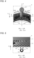
- FIG. 6 is an enlarged view of a region Q shown in FIG. 1 .
- FIG. 7 is a view of the region Q as viewed from behind toward front of the paper surface of FIG. 1 .
- a first counter-welding-side region and a second counter-welding-side region are referred to as a first counter-welding-side region and a second counter-welding-side region, respectively.
- the vertically divided two ranges, a region on the left side when the counter-welding-side coil end part 22 is viewed in the second axial direction A2, that is, a region shown in FIG.
- first counter-welding-side region 222 a region on the right side when the counter-welding-side coil end part is viewed in the second axial direction A2, that is, a region shown in FIG. 7 is referred to as a second counter-welding-side region 223.
- a second cooling medium supply portion 321 which is a tip portion of the second cooling medium pipe 32, is disposed to overlap the counter-welding-side coil end part 22 along the axial direction A, similarly to the first cooling medium supply portion 311 of the first cooling medium pipe 31. More specifically, the second cooling medium supply portion 321 is disposed such that a position of an axis passing through the center of an inner diameter of the second cooling medium supply portion 321 coincides with the central axis of the stator core 11 in the height direction and is higher than the highest position of the counter-welding-side coil end part 22.
- the second cooling medium supply portion 321 is provided with three counter-welding-side discharge holes (a first counter-welding-side discharge hole 61, a second counter-welding-side discharge hole 62, and a third counter-welding-side discharge hole 63).
- the first counter-welding-side discharge hole 61 is provided to discharge the cooling medium along the first circumferential direction R1.
- the first counter-welding-side discharge hole 61 is formed to face the first counter-welding-side region 222 side, and is formed such that the axis of the first counter-welding-side discharge hole 61 coincides with a radial direction of the cylinder of the second cooling medium pipe 32.
- the radial direction of the cylinder of the second cooling medium pipe 32 is a radial direction about the central axis of the cylinder.
- the cooling medium lands on the counter-welding-side coil end part 22 along the first circumferential direction R1 (see FIG. 4 ), and flows in the gravity direction H along the inclinations of the coils 12 in the counter-welding-side coil end part 22.
- each of the second counter-welding-side discharge hole 62 and the third counter-welding-side discharge hole 63 is provided to discharge the cooling medium along the second circumferential direction R2.
- the second counter-welding-side discharge hole 62 is formed to face the second counter-welding-side region 223, and is formed such that the axis of the second counter-welding-side discharge hole 62 coincides with the radial direction of the cylinder of the second cooling medium pipe 32.
- the cooling medium lands on the counter-welding-side coil end part 22 along the second circumferential direction R2 (see FIG. 4 ), and flows in the gravity direction H along the inclinations of the coils 12 in the counter-welding-side coil end part 22.
- the third counter-welding-side discharge hole 63 is also formed to face the second counter-welding-side region 223, and is also formed such that the axis of the third counter-welding-side discharge hole 63 coincides with the radial direction of the cylinder of the second cooling medium pipe 32.
- the respective axial positions of the first counter-welding-side discharge hole 61, the second counter-welding-side discharge hole 62, and the third counter-welding-side discharge hole 63 are different from one another.
- the respective diameter sizes of the second counter-welding-side discharge hole 62 and the third counter-welding-side discharge hole are different from each other.
- the second cooling medium pipe 32 is formed with a fourth cooling medium supply portion 322 branching from the second cooling medium supply portion 321 and extending toward the inner side in the radial direction of the stator core 11, that is, in the gravity direction H.
- the fourth cooling medium supply portion 322 is provided with a fourth counter-welding-side discharge hole 64.
- the fourth counter-welding-side discharge hole 64 discharges, to the counter-welding-side coil end part 22 that the fourth counter-welding-side discharge hole 64 faces in the axial direction A, the cooling medium, toward one side in the circumferential direction, that is, the first counter-welding-side region 222.
- the fourth counter-welding-side discharge hole 64 is formed to face the first counter-welding-side region 222, and is formed such that the axis of the fourth counter-welding-side discharge hole 64 coincides with a radial direction of the cylinder of the fourth cooling medium supply portion 322.
- the radial direction of the cylinder of the fourth cooling medium supply portion 322 is a radial direction about the central axis of the cylinder.
- the fourth counter-welding-side discharge hole 64 is formed such that the axis thereof is angled toward the first horizontal direction C1 with respect to the axial direction A, that is, angled toward the first counter-welding-side region 222.
- the cooling medium is discharged in a direction angled toward the first horizontal direction with respect to the second axial direction A2. Further, the cooling medium flows while being angled in the gravity direction H due to gravity.
- the cooling medium As described in the description of the third cooling medium supply portion 312 with respect to the welding-side coil end part 21, in a case where the cooling medium is discharged from the fourth cooling medium supply portion 322 along the second axial direction A2, the cooling medium is repelled at an end portion 221 of the counter-welding-side coil end part 22.
- the motor cooling device 2 instead of discharging the cooling medium from the fourth cooling medium supply portion 322 along the second axial direction A2, discharges the cooling medium while angling the cooling medium toward the horizontal direction with respect to the second axial direction A2.
- the cooling medium discharged from the fourth counter-welding-side discharge hole 64 lands on the end portion 221 of the counter-welding-side coil end part 22 in a direction of flow along the circumferential direction of the counter-welding-side coil end part 22. Therefore, the cooling medium is hardly repelled in the end portion 221, and a wider range can be covered, in the end portion 221. Note that in the counter-welding-side coil end part 22, a counter-welding-side discharge hole formed to be angled toward the second counter-welding-side region 223 is not formed.
- the first counter-welding-side discharge hole 61 and the fourth counter-welding-side discharge hole 64 are provided for the first counter-welding-side region 222, and the second counter-welding-side discharge hole 62 and the third counter-welding-side discharge hole 63 are provided for the second counter-welding-side region 223.
- the sizes of the holes are adjusted such that an amount of the cooling medium discharged from the first counter-welding-side discharge hole 61 and the fourth counter-welding-side discharge hole 64 is substantially equal to an amount of the cooling medium discharged from the second counter-welding-side discharge hole 62 and the third counter-welding-side discharge hole 63. With this adjustment, the two coil end parts can be equally cooled, and cooling performance can be enhanced.
- the counter-welding-side discharge holes provided for the first counter-welding-side region 222 and the counter-welding-side discharge holes provided for the second counter-welding-side region 223 are preferably disposed such that an amount of the cooling medium discharged toward the first counter-welding-side region 222 is equal to an amount of the cooling medium discharged toward the second counter-welding-side region 223.
- the specific size, position, and number of holes for that purpose are not limited to those of the embodiment.
- the size and number of the holes are preferably adjusted such that an amount of the cooling medium discharged toward the first welding-side region 212 is substantially equal to an amount of the cooling medium discharged toward the second welding-side region 213.
- the counter-welding-side discharge holes are formed to be asymmetric with respect to the vertical plane, in at least one of the number or positions of the counter-welding-side discharge holes.
- the central axis of the second cooling medium supply portion 321 is a plane included in the vertical plane and parallel to the paper surface of FIG. 6 .
- One side in the circumferential direction (one of the first counter-welding-side region 222 or the second counter-welding-side region 223) and the other side in the circumferential direction (the other one of the first counter-welding-side region 222 or the second counter-welding-side region 223) of the counter-welding-side coil end part 22 have respective different inclination directions of the coils, that is, have asymmetric shapes with respect to the vertical plane. Therefore, the inclination directions of the coils 12 are asymmetric with respect to the vertical plane.
- the counter-welding-side discharge holes are formed to be asymmetric in at least one of the number or positions of the counter-welding-side discharge holes, in accordance with such inclination directions of the coils 12.
- a wider range can be covered with the cooling medium, and cooling performance can be enhanced.
- the counter-welding-side coil end part 22 is smaller than the welding-side coil end part 21. That is, the position H12 of the counter-welding-side coil end part 22 in the height direction is higher than the position H11 of the welding-side coil end part 21 in the height direction.
- a position H22 of the second cooling medium supply portion 321 of the second cooling medium pipe 32 in the height direction is lower than a position H21 of the first cooling medium supply portion 311 of the first cooling medium pipe 31 in the height direction. Accordingly, the first welding-side discharge hole 41 and the second welding-side discharge hole 42 provided in the first cooling medium supply portion 311 are different in position in the height direction (gravity direction) from the first counter-welding-side discharge hole 61, the second counter-welding-side discharge hole 62, and the third counter-welding-side discharge hole 63 provided in the second cooling medium supply portion 321.
- a distance from the first cooling medium supply portion 311 of the first cooling medium pipe 31 to the welding-side coil end part 21 is longer than a distance from the second cooling medium supply portion 321 of the second cooling medium pipe 32 to the counter-welding-side coil end part 22.
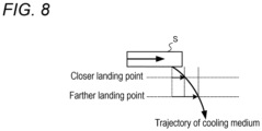
- a trajectory of the cooling medium discharged from a cooling medium pipe S draws a parabola due to a direction of the flow of the cooling medium and gravity.
- the landing point greatly changes when the amount of cooling medium changes, and this makes it difficult to cause the cooling medium to land at a target location. Therefore, as described above, the respective heights of the first cooling medium supply portion 311 of the first cooling medium pipe 31 and the second cooling medium supply portion 321 of the second cooling medium pipe 32 are made different from each other.
- the first welding-side discharge hole 41 and the second welding-side discharge hole 42 provided in the first cooling medium supply portion 311 are different in position in the height direction (gravity direction) from the first counter-welding-side discharge hole 61, the second counter-welding-side discharge hole 62, and the third counter-welding-side discharge hole 63 provided in the second cooling medium supply portion 321.
- the distance from the first cooling medium supply portion 311 to the welding-side coil end part 21 is caused to be substantially equal to the distance from the second cooling medium supply portion 321 to the counter-welding-side coil end part 22.
- the distance from each of the first welding-side discharge hole 41 and the second welding-side discharge hole 4 provided in the first cooling medium supply portion 311 to the welding-side coil end part 21 is caused to be substantially equal to the distance from each of the first counter-welding-side discharge hole 61, the second counter-welding-side discharge hole 62, and the third counter-welding-side discharge hole 63 provided in the second cooling medium supply portion 321 to the counter-welding-side coil end part 22.
- the cooling medium can be caused to land at predetermined positions in the coil end parts, and cooling performance can be enhanced.
- the distance from the first cooling medium supply portion 311 to the welding-side coil end part 21 is preferably such a distance that the cooling medium properly lands on the welding-side coil end part 21.
- the distance from the second cooling medium supply portion 321 to the counter-welding-side coil end part 22 is preferably such a distance that the cooling medium properly lands on the counter-welding-side coil end part 22.
- the first cooling medium pipe 31 that supplies the cooling medium to the welding-side coil end part 21 and the second cooling medium pipe 32 that supplies the cooling medium to the counter-welding-side coil end part 22 are provided separately, and the respective positions of the first cooling medium pipe 31 and the second cooling medium pipe 32 in the gravity direction H are different from each other. Accordingly, flexibility regarding the positions at which the cooling medium pipes 31, 32 can be disposed can be increased. Thus, the cooling medium can be caused to land at respective proper positions for the coil end parts, which are the two coil end parts having different shapes and sizes. Therefore, a range covered with the cooling medium can be secured, and cooling performance can be enhanced.
- the first cooling medium pipe 31 is formed with the third cooling medium supply portion 312 extending toward the inner side in the radial direction
- the second cooling medium pipe 32 is formed with the fourth cooling medium supply portion 322 extending toward the inner side in the radial direction. Accordingly, the cooling medium can be discharged to the end portion 211 of the welding-side coil end part 21 from the axial direction A, and the cooling medium can be discharged to the end portion 221 of the counter-welding-side coil end part 22 from the axial direction A. Thus, cooling performance with respect to the coil end parts can be enhanced.
- the above embodiment is an example for implementing the present invention, and other various embodiments can be adopted.
- the first cooling medium pipe 31 and the second cooling medium pipe 32 need not include the third cooling medium supply portion 312 and the fourth cooling medium supply portion 322, respectively. Also in this case, a wide range of the coils can be covered.
- the third welding-side discharge hole 43 or the fourth welding-side discharge hole may be provided in the third cooling medium supply portion 312 of the first cooling medium pipe 31.
- the third welding-side discharge hole 43 and the fourth welding-side discharge hole may be bilaterally symmetric or asymmetric regarding the respective lateral positions thereof and the respective directions of the hole axes thereof.
- each of the axial positions of the discharge holes facing downward provided in each of the first cooling medium pipe 31 and the second cooling medium pipe 32 are simply required to be different from each other.
- each of the axial positions of the discharge holes facing downward may be designed in accordance with a winding direction of a corresponding one, of the coils, facing the discharge hole.
- the first cooling medium pipe 31 and the second cooling medium pipe 32 are simply required to have different heights, and distances from the cooling medium pipes to the coil end parts need not be necessarily equal.
Landscapes
- Engineering & Computer Science (AREA)
- Power Engineering (AREA)
- Motor Or Generator Cooling System (AREA)
- Manufacture Of Motors, Generators (AREA)
Applications Claiming Priority (2)
| Application Number | Priority Date | Filing Date | Title |
|---|---|---|---|
| JP2022174358 | 2022-10-31 | ||
| PCT/JP2023/036158 WO2024095668A1 (ja) | 2022-10-31 | 2023-10-04 | モータ冷却構造 |
Publications (2)
| Publication Number | Publication Date |
|---|---|
| EP4576518A1 true EP4576518A1 (de) | 2025-06-25 |
| EP4576518A4 EP4576518A4 (de) | 2025-12-24 |
Family
ID=90930345
Family Applications (1)
| Application Number | Title | Priority Date | Filing Date |
|---|---|---|---|
| EP23885431.9A Pending EP4576518A4 (de) | 2022-10-31 | 2023-10-04 | Motorkühlungsstruktur |
Country Status (4)
| Country | Link |
|---|---|
| EP (1) | EP4576518A4 (de) |
| JP (1) | JPWO2024095668A1 (de) |
| CN (1) | CN120113131A (de) |
| WO (1) | WO2024095668A1 (de) |
Family Cites Families (6)
| Publication number | Priority date | Publication date | Assignee | Title |
|---|---|---|---|---|
| JPS52108512U (de) * | 1976-02-16 | 1977-08-18 | ||
| JP2006115652A (ja) | 2004-10-18 | 2006-04-27 | Toyota Motor Corp | 回転電機の冷却装置 |
| JP4919108B2 (ja) * | 2009-03-26 | 2012-04-18 | アイシン・エィ・ダブリュ株式会社 | ステータ |
| US9048710B2 (en) * | 2011-08-29 | 2015-06-02 | Remy Technologies, Llc | Electric machine module cooling system and method |
| US9331543B2 (en) * | 2012-04-05 | 2016-05-03 | Remy Technologies, Llc | Electric machine module cooling system and method |
| JP2016134972A (ja) * | 2015-01-16 | 2016-07-25 | アイシン・エィ・ダブリュ株式会社 | モータ冷却構造 |
-
2023
- 2023-10-04 JP JP2024554327A patent/JPWO2024095668A1/ja active Pending
- 2023-10-04 EP EP23885431.9A patent/EP4576518A4/de active Pending
- 2023-10-04 WO PCT/JP2023/036158 patent/WO2024095668A1/ja not_active Ceased
- 2023-10-04 CN CN202380075112.0A patent/CN120113131A/zh active Pending
Also Published As
| Publication number | Publication date |
|---|---|
| CN120113131A (zh) | 2025-06-06 |
| JPWO2024095668A1 (de) | 2024-05-10 |
| EP4576518A4 (de) | 2025-12-24 |
| WO2024095668A1 (ja) | 2024-05-10 |
Similar Documents
| Publication | Publication Date | Title |
|---|---|---|
| RU2649860C2 (ru) | Устройства для плазменных дуговых горелок с газовым охлаждением и относящиеся к ним системы и способы | |
| CN112039246B (zh) | 旋转电机 | |
| US11962189B2 (en) | Stator for an electric motor and an electric motor | |
| EP3016248B1 (de) | Kühlsystem für rotierende elektrische maschine | |
| US5897059A (en) | Nozzle for use in a torch head of a plasma torch apparatus | |
| WO2012070191A1 (ja) | ステータ冷却装置 | |
| EP3196410A1 (de) | Turbinenendwand und spitzenkühlung für doppelwandige schaufeln | |
| US20180091011A1 (en) | Rotary electric machine | |
| US11722029B2 (en) | Rotary electric machine | |
| EP4576518A1 (de) | Motorkühlungsstruktur | |
| EP3136550A1 (de) | Rotoranordnung mit verbesserter kühlstrecke | |
| US6844637B1 (en) | Rotor assembly end turn cooling system and method | |
| US20160115796A1 (en) | Turbine blade cooling structure | |
| EP2824805A1 (de) | Elektrische rotationsmaschine | |
| EP2662959A2 (de) | Rotierende elektrische Maschine | |
| JP6911699B2 (ja) | 電気自動車を駆動するモータ | |
| EP1389826B1 (de) | Gasschirm für Generator und verwandtes Verfahren | |
| JP2016134972A (ja) | モータ冷却構造 | |
| KR20190093931A (ko) | 헤어핀 권선모터의 고정자 어셈블리 | |
| EP3619436B1 (de) | Gebläse und klimaanlage damit | |
| KR101663360B1 (ko) | 내경가변 전선피복금형 | |
| HK1253937A1 (zh) | 感应式坩埚炉和用於感应式坩埚炉的磁轭 | |
| US12212201B2 (en) | Cooling system, stator for rotating electric machine, and segment coil | |
| CN118345328A (zh) | 用于等离子喷涂机的喷嘴板以及等离子喷涂机 | |
| JP2020089149A (ja) | モータユニット |
Legal Events
| Date | Code | Title | Description |
|---|---|---|---|
| STAA | Information on the status of an ep patent application or granted ep patent |
Free format text: STATUS: THE INTERNATIONAL PUBLICATION HAS BEEN MADE |
|
| PUAI | Public reference made under article 153(3) epc to a published international application that has entered the european phase |
Free format text: ORIGINAL CODE: 0009012 |
|
| STAA | Information on the status of an ep patent application or granted ep patent |
Free format text: STATUS: REQUEST FOR EXAMINATION WAS MADE |
|
| 17P | Request for examination filed |
Effective date: 20250318 |
|
| AK | Designated contracting states |
Kind code of ref document: A1 Designated state(s): AL AT BE BG CH CY CZ DE DK EE ES FI FR GB GR HR HU IE IS IT LI LT LU LV MC ME MK MT NL NO PL PT RO RS SE SI SK SM TR |
|
| A4 | Supplementary search report drawn up and despatched |
Effective date: 20251121 |
|
| RIC1 | Information provided on ipc code assigned before grant |
Ipc: H02K 9/19 20060101AFI20251117BHEP Ipc: H02K 5/20 20060101ALI20251117BHEP Ipc: H02K 3/24 20060101ALI20251117BHEP |
|
| DAV | Request for validation of the european patent (deleted) | ||
| DAX | Request for extension of the european patent (deleted) |