EP4575717A1 - Electronic apparatuses - Google Patents
Electronic apparatuses Download PDFInfo
- Publication number
- EP4575717A1 EP4575717A1 EP23909104.4A EP23909104A EP4575717A1 EP 4575717 A1 EP4575717 A1 EP 4575717A1 EP 23909104 A EP23909104 A EP 23909104A EP 4575717 A1 EP4575717 A1 EP 4575717A1
- Authority
- EP
- European Patent Office
- Prior art keywords
- electronic device
- thermal source
- disposed
- thermal
- cooling liquid
- Prior art date
- Legal status (The legal status is an assumption and is not a legal conclusion. Google has not performed a legal analysis and makes no representation as to the accuracy of the status listed.)
- Pending
Links
Images





Classifications
-
- H—ELECTRICITY
- H02—GENERATION; CONVERSION OR DISTRIBUTION OF ELECTRIC POWER
- H02M—APPARATUS FOR CONVERSION BETWEEN AC AND AC, BETWEEN AC AND DC, OR BETWEEN DC AND DC, AND FOR USE WITH MAINS OR SIMILAR POWER SUPPLY SYSTEMS; CONVERSION OF DC OR AC INPUT POWER INTO SURGE OUTPUT POWER; CONTROL OR REGULATION THEREOF
- H02M1/00—Details of apparatus for conversion
- H02M1/42—Circuits or arrangements for compensating for or adjusting power factor in converters or inverters
- H02M1/4208—Arrangements for improving power factor of AC input
-
- G—PHYSICS
- G01—MEASURING; TESTING
- G01R—MEASURING ELECTRIC VARIABLES; MEASURING MAGNETIC VARIABLES
- G01R31/00—Arrangements for testing electric properties; Arrangements for locating electric faults; Arrangements for electrical testing characterised by what is being tested not provided for elsewhere
- G01R31/001—Measuring interference from external sources to, or emission from, the device under test, e.g. EMC, EMI, EMP or ESD testing
-
- G—PHYSICS
- G01—MEASURING; TESTING
- G01R—MEASURING ELECTRIC VARIABLES; MEASURING MAGNETIC VARIABLES
- G01R31/00—Arrangements for testing electric properties; Arrangements for locating electric faults; Arrangements for electrical testing characterised by what is being tested not provided for elsewhere
- G01R31/001—Measuring interference from external sources to, or emission from, the device under test, e.g. EMC, EMI, EMP or ESD testing
- G01R31/002—Measuring interference from external sources to, or emission from, the device under test, e.g. EMC, EMI, EMP or ESD testing where the device under test is an electronic circuit
-
- G—PHYSICS
- G06—COMPUTING OR CALCULATING; COUNTING
- G06F—ELECTRIC DIGITAL DATA PROCESSING
- G06F1/00—Details not covered by groups G06F3/00 - G06F13/00 and G06F21/00
- G06F1/16—Constructional details or arrangements
- G06F1/20—Cooling means
-
- H—ELECTRICITY
- H02—GENERATION; CONVERSION OR DISTRIBUTION OF ELECTRIC POWER
- H02M—APPARATUS FOR CONVERSION BETWEEN AC AND AC, BETWEEN AC AND DC, OR BETWEEN DC AND DC, AND FOR USE WITH MAINS OR SIMILAR POWER SUPPLY SYSTEMS; CONVERSION OF DC OR AC INPUT POWER INTO SURGE OUTPUT POWER; CONTROL OR REGULATION THEREOF
- H02M1/00—Details of apparatus for conversion
- H02M1/42—Circuits or arrangements for compensating for or adjusting power factor in converters or inverters
-
- H—ELECTRICITY
- H02—GENERATION; CONVERSION OR DISTRIBUTION OF ELECTRIC POWER
- H02M—APPARATUS FOR CONVERSION BETWEEN AC AND AC, BETWEEN AC AND DC, OR BETWEEN DC AND DC, AND FOR USE WITH MAINS OR SIMILAR POWER SUPPLY SYSTEMS; CONVERSION OF DC OR AC INPUT POWER INTO SURGE OUTPUT POWER; CONTROL OR REGULATION THEREOF
- H02M1/00—Details of apparatus for conversion
- H02M1/42—Circuits or arrangements for compensating for or adjusting power factor in converters or inverters
- H02M1/4208—Arrangements for improving power factor of AC input
- H02M1/4225—Arrangements for improving power factor of AC input using a non-isolated boost converter
-
- H—ELECTRICITY
- H02—GENERATION; CONVERSION OR DISTRIBUTION OF ELECTRIC POWER
- H02M—APPARATUS FOR CONVERSION BETWEEN AC AND AC, BETWEEN AC AND DC, OR BETWEEN DC AND DC, AND FOR USE WITH MAINS OR SIMILAR POWER SUPPLY SYSTEMS; CONVERSION OF DC OR AC INPUT POWER INTO SURGE OUTPUT POWER; CONTROL OR REGULATION THEREOF
- H02M1/00—Details of apparatus for conversion
- H02M1/44—Circuits or arrangements for compensating for electromagnetic interference in converters or inverters
-
- H—ELECTRICITY
- H02—GENERATION; CONVERSION OR DISTRIBUTION OF ELECTRIC POWER
- H02M—APPARATUS FOR CONVERSION BETWEEN AC AND AC, BETWEEN AC AND DC, OR BETWEEN DC AND DC, AND FOR USE WITH MAINS OR SIMILAR POWER SUPPLY SYSTEMS; CONVERSION OF DC OR AC INPUT POWER INTO SURGE OUTPUT POWER; CONTROL OR REGULATION THEREOF
- H02M7/00—Conversion of AC power input into DC power output; Conversion of DC power input into AC power output
-
- H—ELECTRICITY
- H02—GENERATION; CONVERSION OR DISTRIBUTION OF ELECTRIC POWER
- H02M—APPARATUS FOR CONVERSION BETWEEN AC AND AC, BETWEEN AC AND DC, OR BETWEEN DC AND DC, AND FOR USE WITH MAINS OR SIMILAR POWER SUPPLY SYSTEMS; CONVERSION OF DC OR AC INPUT POWER INTO SURGE OUTPUT POWER; CONTROL OR REGULATION THEREOF
- H02M7/00—Conversion of AC power input into DC power output; Conversion of DC power input into AC power output
- H02M7/02—Conversion of AC power input into DC power output without possibility of reversal
-
- H—ELECTRICITY
- H05—ELECTRIC TECHNIQUES NOT OTHERWISE PROVIDED FOR
- H05K—PRINTED CIRCUITS; CASINGS OR CONSTRUCTIONAL DETAILS OF ELECTRIC APPARATUS; MANUFACTURE OF ASSEMBLAGES OF ELECTRICAL COMPONENTS
- H05K7/00—Constructional details common to different types of electric apparatus
- H05K7/20—Modifications to facilitate cooling, ventilating, or heating
- H05K7/20709—Modifications to facilitate cooling, ventilating, or heating for server racks or cabinets; for data centers, e.g. 19-inch computer racks
- H05K7/20763—Liquid cooling without phase change
- H05K7/20772—Liquid cooling without phase change within server blades for removing heat from heat source
-
- G—PHYSICS
- G06—COMPUTING OR CALCULATING; COUNTING
- G06F—ELECTRIC DIGITAL DATA PROCESSING
- G06F2200/00—Indexing scheme relating to G06F1/04 - G06F1/32
- G06F2200/20—Indexing scheme relating to G06F1/20
- G06F2200/201—Cooling arrangements using cooling fluid
Definitions
- the present invention relates to an electronic device and more particularly to an electronic device with reduced cost.
- the electronic device includes a fan for dissipating the thermal of electronic component disposed within the electronic device.
- the fan is omitted in the electronic device for increasing the space. Consequently, a great volume of cooling liquid is immersed to the cooling slot to fill the space of the electronic device. The cost of the cooling liquid is increased.
- the present disclosure provides an electronic device.
- the electronic device includes a filling component.
- the filling component covers the electronic component and the carrier portion, or disposed between the electronic components of the electronic device, or disposed between the electronic component and the mechanical component, or disposed in the space between the mechanical components. Consequently, when the electronic device is disposed in the cooling slot, the filling component fills in the space within the electronic device. The volume and the cost of the cooling liquid are reduced.
- the electronic device of the present disclosure includes a liquid channel.
- the flow direction or the flow speed of the cooling liquid are limited through the liquid channel.
- the convection capability of the cooling liquid passing through the liquid channel is enhanced. Consequently, the dissipation capability of the cooling liquid for the thermal source region is enhanced.
- the electronic device of the present disclosure includes an accommodation space for receiving the filling component. The volume and the cost of the cooling liquid passing through the accommodation space are reduced.
- an electronic device is disposed in a cooling liquid of a cooling slot.
- the electronic device includes a carrier portion, an electronic component, a thermal source region and a filling component.
- the electronic component is disposed on the carrier portion and includes a thermal source.
- the thermal source region is disposed in the carrier portion and corresponding in position to the thermal source.
- the filling component is disposed on the electronic component and includes at least one liquid channel.
- the at least one liquid channel runs through the filling component.
- the at least one liquid channel is communicated with the thermal source region for limiting or guiding the cooling liquid from passing through the thermal source region.
- the cooling liquid is configured to exchange a thermal with the thermal source region.
- an electronic device is disposed in a cooling liquid of a cooling slot.
- the electronic device includes a carrier portion, an electronic component, a thermal source region and a filling component.
- the carrier portion includes a first accommodation space.
- the first accommodation space is formed within the carrier portion.
- the electronic component is disposed on the carrier portion and includes a thermal source.
- the thermal source region is disposed in the carrier portion and corresponding in position to the thermal source.
- the filling component is a sealed structure and fills in the first accommodation space for limiting or avoiding the cooling liquid from immersing into the first accommodation space.
- the filling component is configured to limit or guide the cooling liquid from passing through the thermal source region.
- the cooling liquid is configured to exchange a thermal with the thermal source region.
- an electronic device is disposed in a cooling liquid of a cooling slot.
- the electronic device includes a carrier portion, an electronic component, a thermal source region and a filling component.
- the carrier portion includes a plurality of side walls and a carrier main body. The plurality of side walls are disposed around the carrier main body to form a first accommodation space and a second accommodation space.
- the electronic component includes a thermal source disposed in the second accommodation space of the carrier portion.
- the thermal source region is disposed in the carrier portion and corresponding in position to the thermal source.
- the filling component is disposed in the first accommodation space for limiting or avoiding the cooling liquid from immersing into the first accommodation space.
- the filling component is configured to limit or guide the cooling liquid from passing through the thermal source region, and the cooling liquid is configured to exchange a thermal with the thermal source region.
- FIG. 1 is a schematic view illustrating an electronic device according to a first embodiment of the present disclosure.
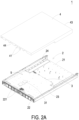
- FIG. 2A is a schematic exploded view illustrating the electronic device as shown in FIG. 1 .
- FIG. 2B is a schematic exploded view illustrating the electronic device as shown in FIG. 1 taken along another viewpoint.
- FIG. 3 is a schematic cross-sectional view illustrating the electronic device as shown in FIG. 1 taken along the line A-A'.
- the electronic device 1 of this embodiment is an industrial electronic device.
- the electronic device 1 is CRPS/MCRPS power supply, industrial power supply, server power supply, server, or networking device.
- the electronic device 1 is disposed within a cooling liquid of a cooling slot (not shown) for dissipating the thermal of the electronic device 1.
- the electronic device 1 includes a carrier portion 2, an electronic component 3, a filling component 4 and a thermal source region 5.
- the carrier portion 2 is an insulation structure for carrying the electronic component 3 and the filling component 4.
- the electronic device 3 is disposed on the carrier portion 2 and includes a thermal source 31.
- the thermal source 31 is central processing unit (CPU), dual in-line memory module (DIMM), PCIe card, graphics processing unit (GPU), electronic circuit, busbar, thermal sink, any thermal generating electronic component or thermal conductive structure.
- the thermal source region 5 is any region of the electronic device 1 requiring the cooling liquid for exchanging the thermal.
- the thermal source region 5 is disposed on the carrier portion 2 and corresponding to nearby region of the thermal source 31 of the electronic component 3.
- the thermal source region 5 corresponding to the thermal source 31 dissipates the thermal through the cooling liquid.
- the filling component 4 is a one-piece structure.
- the filling component 4 covers the electronic component 3 and the carrier portion 2.
- the electronic component 3 is disposed between the filling component 4 and the carrier portion 2.
- the filling component 4 includes at least one fluid channel 41, a thermal dissipation portion 42, a first flow hole 43 and a second flow hole 44.
- the liquid channel 41 passes through the two sides of the filling component 4.
- the liquid channel 41 and the thermal source region 5 are spatially corresponding in position to each other.
- the thermal source region 5 is disposed within the corresponding liquid channel 41. Namely, the thermal source region 5 is completely contained in the liquid channel 41.
- a portion structure of the liquid channel 41 forms the thermal dissipation portion 42.
- At least a portion of the thermal dissipation portion 42 and the thermal source region 5 of the electronic device 1 are spatially corresponding in position to each other.
- at least a portion of the thermal dissipation portion 42 and the thermal source 31 are spatially corresponding in position to each other, as shown in FIG. 3 .
- the first flow hole 43 and the second flow hole 44 are disposed on two opposite sides of the liquid channel 41.
- the cooling liquid passes through the liquid channel 41 through the first flow hole 43.
- the liquid channel 41 limits or guides the cooling liquid from passing through the thermal source region 5.
- the cooling liquid exchanges the thermal with the thermal source region 5.
- the cooling liquid flows out from the liquid channel 41 through the second flow hole 44. Consequently, the cooling liquid dissipates the thermal of the thermal source 31 of the thermal source region 5.
- the filling component 4 is waterproof foam, plastic structure, metal structure or any structure adapting to the cooling liquid.
- the filling component 4 occupies the space within the electronic device 1 so as to reduce the volume of the cooling liquid, and/or the residual space formed by the filling component 4 limits the flow direction or the flow speed of the cooling liquid. Consequently, the thermal dissipation capability of the cooling liquid to the thermal source 31 of the thermal source region 5 is enhanced.
- the electronic device 1 of the present disclosure includes a filling component 4.
- the filling component 4 covers the electronic component 3 and the carrier portion 2.
- the space within the electronic device 1 is reduced so as to reduce the volume and the cost of the cooling liquid.
- the filling component 4 of the electronic device 1 of the present disclosure includes a liquid channel 41 running through the two sides of the filling component 4.
- the liquid channel 41 limits or guides the cooling liquid passing through the thermal source region 5.
- the cooling liquid exchanges the thermal with the thermal source region 5.
- the convection capability of the cooling liquid passing through the liquid channel 41 is enhanced. Consequently, the cooling liquid dissipates the thermal of the thermal source 31 of the thermal source region 5.
- the carrier portion 2 includes a carrier main body 21 and a plurality of side walls.
- the plurality of side walls includes a front wall 22, a first side wall 23 and a second side wall 24.
- the first side wall 23, the front wall 22 and the second side wall 24 are disposed around and connected with the carrier main body 21.
- the first side wall 23 and the second side wall 24 are opposite to each other.
- the front side wall 22 is disposed between the first side wall 23 and the second side wall 24.
- the front side wall 22 includes a plurality of first through holes 221 arranged in sequence. The arrangement direction of the plurality of first through holes 221 is parallel to the direction from the first side wall 23 toward the second side wall 24. Each first through hole 221 runs through the front side wall 22.
- the first through hole 221 is at least partially communicated with the second flow hole 44 of the filling component 4.
- the electronic device 1 receives the cooling liquid through the first flow hole 43 of the filling component 4.
- the cooling liquid passes through the first flow hole 43, the liquid channel 41, the second flow hole 44 and the first through hole 221 of the front side wall 22 of the carrier portion 2 in sequence.
- the electronic component 3 is disposed on the carrier main body 21 of the carrier portion 2, disposed between the first side wall 23 and the second side wall 24 of the carrier portion 2, and adjacent to the front side wall 22 of the carrier portion 2.
- the front side wall 22, the first side wall 23, the second side wall 24 and the electronic component 3 defines the thermal source region 5 collaboratively.
- the fan is disposed in the thermal source region 5, so that the thermal is dissipated through airflow.
- the thermal source region 5 is empty to form a space.
- the filling component 4 is disposed in the thermal source region 5 on the electronic component 3, disposed between the first side wall 23 and the second side wall 24 of the carrier portion 5, and adjacent to the front side wall 22 of the carrier portion 2.
- the electronic component 3 is disposed between the filling component 4 and the carrier main body 21 of the carrier portion 2.
- the electronic component 3 is covered by the carrier portion 2 and the filling component 4 collaboratively.
- each liquid channel 41 runs through the filling component 4.
- the extension direction of each liquid channel 41 is parallel to the first side wall 23 and the second side wall 24 of the carrier portion 2.
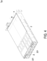
- FIG. 4 is a schematic view illustrating an electronic device according to a second embodiment of the present disclosure.
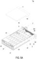
- FIG. 5A is a schematic exploded view illustrating the electronic device as shown in FIG. 4 .
- FIG. 5B is a schematic exploded view illustrating the electronic device as shown in FIG. 4 taken along another viewpoint.
- FIG. 6 is a schematic cross-sectional view illustrating the electronic device as shown in FIG. 4 taken along the line A-A'.
- the carrier portion 2 of the electronic device 1a of this embodiment includes a rear side wall 25.
- the rear side wall 25 and the front side wall 22 are opposite to each other and disposed between the first side wall 23 and the second side wall 24.
- the rear side wall 25 includes a plurality of second through holes 251. Each second through hole 251 runs through the rear side wall 25.
- the cooling liquid passes through the second through hole 251 of the rear side wall 25 of the carrier portion 2 of the electronic device 1a.
- the front side wall 22, the first side wall 23, the rear side wall 25 and the second side wall 24 are disposed around and connected with the carrier main body 21 so as to form an internal space.
- the cooling liquid passes through the internal space formed by the front side wall 22, the first side wall 23, the rear side wall 25, the second side wall 24 and the carrier main body 21 of the carrier portion 2.
- the internal space of the electronic device 1a includes a first separated space 61 and a second separated space 62.
- the first separated space 61 and the second separated space 62 are two spaces isolated from the carrier portion 2 of the electronic device 1a.
- the first separated space 61 and the second separated space 62 are the upper space and the lower space of the electronic device 1a, respectively.
- the filling component 4 of the electronic device 1a includes a first filling part 4a. At least a portion of the first filling part 4a is disposed in the first separated space 61.
- the first filling part 4a is a sealed structure for limiting or avoiding the cooling liquid from immersing to the first separated space 61.
- the filling component 4 includes a second filling part 4b. At least a portion of the second filling part 4b is disposed in the second separated space 62.
- the thermal source region 5 of this embodiment is disposed in the second separated space 62.
- the liquid channel 41 is disposed in the second filling part 4b in communication with the thermal source region. Namely, at least a portion of the thermal source region 5 is contained within the liquid channel 41.
- a portion structure of the liquid channel 41 forms the thermal dissipation portion 42. At least a portion of the thermal dissipation portion 42 and the thermal source region 5 are spatially corresponding in position to each other. For example, at least a portion of the thermal dissipation portion 42 and the thermal source region 5 are spatially corresponding in position to each other.
- the first flow hole 43 and the second flow hole 44 are disposed on two opposite sides of the liquid channel 41, respectively.
- the cooling liquid passes through the liquid channel 41 through the first flow hole 43.
- the liquid channel 41 limits or guides the cooling liquid from passing through the thermal source region 5.
- the cooling liquid exchanges the thermal with the thermal source region 5.
- the cooling liquid flows out from the liquid channel 41 through the second flow hole 44.
- the electronic device 1a of this embodiment is a power rack.
- a portion of the thermal source 31 of the electronic component 3 of the electronic device 1a has reduced thermal dissipation requirement.
- the thermal source 31 is away from the carrier main body 21 of the carrier portion 2 and disposed in the first separated space 61.
- the other portion of the thermal source 31 of the electronic component 3 of the electronic device 1a has enhanced thermal dissipation requirement.
- the thermal source 31 is adjacent to the carrier main body 21 of the carrier portion 2 and disposed in the second separated space 62 so as to dissipate the thermal through the cooling liquid passing through the second separated space 62.
- at least a portion of the first flow hole 43 and/or the second flow hole 44 is communicated with the second through hole 251.
- the cooling liquid passes through the second through hole 251, the first flow hole 43 and the second flow hole 44, so that the thermal of the thermal source 31 is taken away from the thermal source region 5.
- the second filling part 4b is partially disposed in the second separated space 62 of the electronic device 1a. Namely, a portion of the second filling part 4b is not disposed in the second separated space 62. Consequently, the cooling liquid passes through the space of the second separated space 62 unoccupied by the second filling part 4b. The cooling liquid required by the second separated space 62 of the electronic device 1a is provided.
- the first separated space 61 and the second separated space 62 of the electronic device 1a are not limited to the upper space and the lower space separated by the partition of the carrier portion 2.
- the first separated space 61 and the second separated space 62 can be the left side and the right side of the electronic device 1a separated by the partition of the carrier portion 2, respectively.
- the first separated space 61 and the second separated space 62 can be any two spaces separated by the partition of the carrier portion 2, respectively.
- the carrier portion 2 of the electronic device 1a further includes a plurality of third accommodation spaces 27.
- the plurality of third accommodation space 27 are disposed in the front side wall 22 of the carrier portion 2 for receiving the power unit (not shown) or the data storage device (not shown) of the power rack.
- the data storage device can be hard disk drive or random-access memory.
- at least one of the plurality of third accommodation spaces 27 includes an accommodation filling component (not shown). The accommodation filling component limits or avoids the cooling liquid from passing through the corresponding third accommodation space 27. Consequently, the volume of the cooling liquid in the third accommodation space 27 is reduced.
- FIG. 7 is a schematic view illustrating an electronic device according to a third embodiment of the present disclosure.
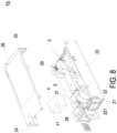
- FIG. 8 is a schematic exploded view illustrating the electronic device as shown in FIG. 7 .
- the electronic device 1b of this embodiment is an industrial electronic device.
- the electronic device 1b is CRPS/MCRPS power supply, industrial power supply, server power supply, server, or networking device.
- the carrier portion 2 of the electronic device 1b further includes a third side wall 26.
- the third side wall 26 and the carrier main body 21 are opposite to each other, disposed between the first side wall 23 and the second side wall 24, and disposed between the front side wall 22 and the rear side wall 25.
- the electronic component 3 and the filling component 4 are disposed on the carrier portion 2.
- the electronic component 3 and the filling component 4 are disposed between the third side wall 26 and the carrier main body 21, disposed between the front side wall 22 and the rear side wall 25, and disposed between the first side wall 23 and the second side wall 24.
- the electronic component 3 includes a thermal source 31.
- the thermal source region 5 is disposed in the carrier portion 2 adjacent to the thermal source 31.
- the second side wall 24, the third side wall 26 and the rear side wall 25 of the carrier portion 2 are integrally formed into one piece.
- the first side wall 23, the front side wall 22 and the carrier main body 21 are integrally formed into one piece.
- the carrier portion 2 further includes a first accommodation space 28 and a second accommodation space 29.
- the first accommodation space 28 and the second accommodation space 29 are defined by the first side wall 23, the third side wall 26, the front side wall 22, the carrier main body 21 and a portion of the electronic component 3 collaboratively.
- the first accommodation space 28 and a second accommodation space 29 are two spaces within the carrier portion 2.
- the first accommodation space 28 is adjacent to the front side wall 2.
- the filling component 4 fills in the first accommodation space 28 for limiting or avoiding the cooling liquid from immersing to the first accommodation space 28.
- the second accommodation space 29 is adjacent to the rear side wall 25. At least a portion of the thermal source 31 of the electronic component 3 is disposed within the second accommodation space 29.
- the thermal source region 5 is disposed in the second accommodation space 29.
- the filling component 4 limits or guides the cooling liquid from passing through the thermal source region 5.
- the cooling liquid exchanges the thermal with the thermal source region 5.
- the first accommodation space 28 and the second accommodation space 29 are dispose in two sides of the carrier portion 2.
- the first accommodation space 28 and the second accommodation space 29 receive the corresponding electrical module, respectively.
- the electrical module is hot-plugged into the first accommodation space 28 and the second accommodation space 29 from the exterior of the electronic device 1b through the two sides of the carrier portion 2.
- the electronic device of the present disclosure includes a filling component.
- the filling component covers the electronic component and the carrier portion, or disposed between the electronic components of the electronic device, or disposed between the electronic component and the mechanical component, or disposed in the space between the mechanical components. Consequently, when the electronic device is disposed in the cooling slot, the filling component fills in the space within the electronic device. The volume and the cost of the cooling liquid are reduced.
- the filling component of the electronic device of the present disclosure includes a liquid channel. The flow direction or the flow speed of the cooling liquid are limited through the liquid channel. The convection capability of the cooling liquid passing through the liquid channel is enhanced. Consequently, the dissipation capability of the cooling liquid for the thermal source region is enhanced.
- the filling portion of the electronic device of the present disclosure includes a first filling part and a second filling part disposed in the first separated space and the second separated space for limiting or avoiding the cooling liquid from immersing to the first separated space and the second separated space.
- the second filling part further includes a liquid channel for guiding the cooling liquid to flow to the second separated space. Consequently, the cooling liquid required by the second separated space for exchanging the thermal is provided.
Landscapes
- Engineering & Computer Science (AREA)
- Physics & Mathematics (AREA)
- Power Engineering (AREA)
- Electromagnetism (AREA)
- General Physics & Mathematics (AREA)
- Theoretical Computer Science (AREA)
- General Engineering & Computer Science (AREA)
- Human Computer Interaction (AREA)
- Microelectronics & Electronic Packaging (AREA)
- Thermal Sciences (AREA)
- Computer Hardware Design (AREA)
- Cooling Or The Like Of Electrical Apparatus (AREA)
- Casings For Electric Apparatus (AREA)
- Feedback Control In General (AREA)
- Cooling Or The Like Of Semiconductors Or Solid State Devices (AREA)
- Filters And Equalizers (AREA)
Abstract
An electronic device is provided. The electronic device is disposed in a cooling liquid of a cooling slot. The electronic device includes a carrier portion, an electronic component, a thermal source region and a filling component. The carrier portion includes a plurality of side walls and a carrier main body. The plurality of side walls are disposed around the carrier main body to form a first accommodation space and a second accommodation space. The electronic component includes a thermal source disposed in the second accommodation space of the carrier portion. The thermal source region is disposed in the carrier portion and corresponding in position to the thermal source. The filling component is disposed in the first accommodation space for limiting or avoiding the cooling liquid from immersing into the first accommodation space. The filling component is configured to limit or guide the cooling liquid from passing through the thermal source region, and the cooling liquid is configured to exchange a thermal with the thermal source region.
Description
- The present invention relates to an electronic device and more particularly to an electronic device with reduced cost.
- In general, the electronic device includes a fan for dissipating the thermal of electronic component disposed within the electronic device. In the practical application, when the electronic device is disposed within the cooling slot for dissipating the thermal by the cooling liquid, the fan is omitted in the electronic device for increasing the space. Consequently, a great volume of cooling liquid is immersed to the cooling slot to fill the space of the electronic device. The cost of the cooling liquid is increased.
- Therefore, there is a need of providing an electronic device to obviate the drawbacks encountered from the prior arts.
- The present disclosure provides an electronic device. The electronic device includes a filling component. The filling component covers the electronic component and the carrier portion, or disposed between the electronic components of the electronic device, or disposed between the electronic component and the mechanical component, or disposed in the space between the mechanical components. Consequently, when the electronic device is disposed in the cooling slot, the filling component fills in the space within the electronic device. The volume and the cost of the cooling liquid are reduced.
- Moreover, the electronic device of the present disclosure includes a liquid channel. The flow direction or the flow speed of the cooling liquid are limited through the liquid channel. The convection capability of the cooling liquid passing through the liquid channel is enhanced. Consequently, the dissipation capability of the cooling liquid for the thermal source region is enhanced.
- Moreover, the electronic device of the present disclosure includes an accommodation space for receiving the filling component. The volume and the cost of the cooling liquid passing through the accommodation space are reduced.
- In accordance with an aspect of the present disclosure, there is provided an electronic device. The electronic device is disposed in a cooling liquid of a cooling slot. The electronic device includes a carrier portion, an electronic component, a thermal source region and a filling component. The electronic component is disposed on the carrier portion and includes a thermal source. The thermal source region is disposed in the carrier portion and corresponding in position to the thermal source. The filling component is disposed on the electronic component and includes at least one liquid channel. The at least one liquid channel runs through the filling component. The at least one liquid channel is communicated with the thermal source region for limiting or guiding the cooling liquid from passing through the thermal source region. The cooling liquid is configured to exchange a thermal with the thermal source region.
- In accordance with another aspect of the present disclosure, there is provided an electronic device. The electronic device is disposed in a cooling liquid of a cooling slot. The electronic device includes a carrier portion, an electronic component, a thermal source region and a filling component. The carrier portion includes a first accommodation space. The first accommodation space is formed within the carrier portion. The electronic component is disposed on the carrier portion and includes a thermal source. The thermal source region is disposed in the carrier portion and corresponding in position to the thermal source. The filling component is a sealed structure and fills in the first accommodation space for limiting or avoiding the cooling liquid from immersing into the first accommodation space. The filling component is configured to limit or guide the cooling liquid from passing through the thermal source region. The cooling liquid is configured to exchange a thermal with the thermal source region.
- In accordance with another aspect of the present disclosure, there is provided an electronic device. The electronic device is disposed in a cooling liquid of a cooling slot. The electronic device includes a carrier portion, an electronic component, a thermal source region and a filling component. The carrier portion includes a plurality of side walls and a carrier main body. The plurality of side walls are disposed around the carrier main body to form a first accommodation space and a second accommodation space. The electronic component includes a thermal source disposed in the second accommodation space of the carrier portion. The thermal source region is disposed in the carrier portion and corresponding in position to the thermal source. The filling component is disposed in the first accommodation space for limiting or avoiding the cooling liquid from immersing into the first accommodation space. The filling component is configured to limit or guide the cooling liquid from passing through the thermal source region, and the cooling liquid is configured to exchange a thermal with the thermal source region.
-
-
FIG. 1 is a schematic view illustrating an electronic device according to a first embodiment of the present disclosure; -
FIG. 2A is a schematic exploded view illustrating the electronic device as shown inFIG. 1 ; -
FIG. 2B is a schematic exploded view illustrating the electronic device as shown inFIG. 1 taken along another viewpoint; -
FIG. 3 is a schematic cross-sectional view illustrating the electronic device as shown inFIG. 1 taken along the line A-A'; -
FIG. 4 is a schematic view illustrating an electronic device according to a second embodiment of the present disclosure; -
FIG. 5A is a schematic exploded view illustrating the electronic device as shown inFIG. 4 ; -
FIG. 5B is a schematic exploded view illustrating the electronic device as shown inFIG. 4 taken along another viewpoint; -
FIG. 6 is a schematic cross-sectional view illustrating the electronic device as shown inFIG. 4 taken along the line A-A'; -
FIG. 7 is a schematic view illustrating an electronic device according to a third embodiment of the present disclosure; and -
FIG. 8 is a schematic exploded view illustrating the electronic device as shown inFIG. 7 . - Description of reference numerals:
- 1, 1a, 1b: electronic device
- 2: carrier portion
- 21: carrier main body
- 22: front side wall
- 221: first through hole
- 23: first side wall
- 24: second side wall
- 25: rear side wall
- 251: second through hole
- 26: third side wall
- 27: third accommodation space
- 28: first accommodation space
- 29: second accommodation space
- 3: electronic component
- 31: thermal source
- 5: thermal source region
- 4: filling component
- 4a: first filling part
- 4b: second filling part
- 41: liquid channel
- 42: thermal dissipation portion
- 43: first flow hole
- 44: second flow hole
- 61: first separated space
- 62: second separated space
- The present disclosure will now be described more specifically with reference to the following embodiments. It is to be noted that the following descriptions of preferred embodiments of this invention are presented herein for purpose of illustration and description only. It is not intended to be exhaustive or to be limited to the precise form disclosed.
-
FIG. 1 is a schematic view illustrating an electronic device according to a first embodiment of the present disclosure.FIG. 2A is a schematic exploded view illustrating the electronic device as shown inFIG. 1 .FIG. 2B is a schematic exploded view illustrating the electronic device as shown inFIG. 1 taken along another viewpoint.FIG. 3 is a schematic cross-sectional view illustrating the electronic device as shown inFIG. 1 taken along the line A-A'. Theelectronic device 1 of this embodiment is an industrial electronic device. For example, theelectronic device 1 is CRPS/MCRPS power supply, industrial power supply, server power supply, server, or networking device. Theelectronic device 1 is disposed within a cooling liquid of a cooling slot (not shown) for dissipating the thermal of theelectronic device 1. Theelectronic device 1 includes acarrier portion 2, anelectronic component 3, afilling component 4 and athermal source region 5. - The
carrier portion 2 is an insulation structure for carrying theelectronic component 3 and thefilling component 4. Theelectronic device 3 is disposed on thecarrier portion 2 and includes athermal source 31. Thethermal source 31 is central processing unit (CPU), dual in-line memory module (DIMM), PCIe card, graphics processing unit (GPU), electronic circuit, busbar, thermal sink, any thermal generating electronic component or thermal conductive structure. Thethermal source region 5 is any region of theelectronic device 1 requiring the cooling liquid for exchanging the thermal. For example, thethermal source region 5 is disposed on thecarrier portion 2 and corresponding to nearby region of thethermal source 31 of theelectronic component 3. Thethermal source region 5 corresponding to thethermal source 31 dissipates the thermal through the cooling liquid. - The filling
component 4 is a one-piece structure. The fillingcomponent 4 covers theelectronic component 3 and thecarrier portion 2. Theelectronic component 3 is disposed between the fillingcomponent 4 and thecarrier portion 2. The fillingcomponent 4 includes at least onefluid channel 41, athermal dissipation portion 42, afirst flow hole 43 and asecond flow hole 44. Theliquid channel 41 passes through the two sides of thefilling component 4. Theliquid channel 41 and thethermal source region 5 are spatially corresponding in position to each other. For example, thethermal source region 5 is disposed within the correspondingliquid channel 41. Namely, thethermal source region 5 is completely contained in theliquid channel 41. In an embodiment, a portion structure of theliquid channel 41 forms thethermal dissipation portion 42. At least a portion of thethermal dissipation portion 42 and thethermal source region 5 of theelectronic device 1 are spatially corresponding in position to each other. For example, at least a portion of thethermal dissipation portion 42 and thethermal source 31 are spatially corresponding in position to each other, as shown inFIG. 3 . Thefirst flow hole 43 and thesecond flow hole 44 are disposed on two opposite sides of theliquid channel 41. The cooling liquid passes through theliquid channel 41 through thefirst flow hole 43. Theliquid channel 41 limits or guides the cooling liquid from passing through thethermal source region 5. The cooling liquid exchanges the thermal with thethermal source region 5. The cooling liquid flows out from theliquid channel 41 through thesecond flow hole 44. Consequently, the cooling liquid dissipates the thermal of thethermal source 31 of thethermal source region 5. - The space within the
electronic device 1 of the present disclosure is filled through the volume of thefilling component 4 for reducing the volume of the cooling liquid, so that the flow direction or the flow speed of the cooling liquid is limited. Consequently, the thermal dissipation capability of the cooling liquid to thethermal source 31 of thethermal source region 5 is enhanced. For example, the fillingcomponent 4 can be waterproof foam or other types of foam with low absorption or non-absorption properties. In some embodiments, the fillingcomponent 4 is plastic structure formed through processes such as plastic injection molding or blow molding. Preferably, the fillingcomponent 4 is a sealed plastic structure with a hollow portion. Alternatively, the fillingcomponent 4 can be a metal structure or other types of material capable of adapting to the cooling liquid. For example, the fillingcomponent 4 is waterproof foam, plastic structure, metal structure or any structure adapting to the cooling liquid. The fillingcomponent 4 occupies the space within theelectronic device 1 so as to reduce the volume of the cooling liquid, and/or the residual space formed by the fillingcomponent 4 limits the flow direction or the flow speed of the cooling liquid. Consequently, the thermal dissipation capability of the cooling liquid to thethermal source 31 of thethermal source region 5 is enhanced. - From above, the
electronic device 1 of the present disclosure includes afilling component 4. The fillingcomponent 4 covers theelectronic component 3 and thecarrier portion 2. When theelectronic device 1 is disposed in the cooling slot, the space within theelectronic device 1 is reduced so as to reduce the volume and the cost of the cooling liquid. Moreover, the fillingcomponent 4 of theelectronic device 1 of the present disclosure includes aliquid channel 41 running through the two sides of thefilling component 4. Theliquid channel 41 limits or guides the cooling liquid passing through thethermal source region 5. The cooling liquid exchanges the thermal with thethermal source region 5. The convection capability of the cooling liquid passing through theliquid channel 41 is enhanced. Consequently, the cooling liquid dissipates the thermal of thethermal source 31 of thethermal source region 5. - Please refers to
FIGS. 2A and2B again. Thecarrier portion 2 includes a carriermain body 21 and a plurality of side walls. The plurality of side walls includes afront wall 22, afirst side wall 23 and asecond side wall 24. Thefirst side wall 23, thefront wall 22 and thesecond side wall 24 are disposed around and connected with the carriermain body 21. Thefirst side wall 23 and thesecond side wall 24 are opposite to each other. Thefront side wall 22 is disposed between thefirst side wall 23 and thesecond side wall 24. Thefront side wall 22 includes a plurality of first throughholes 221 arranged in sequence. The arrangement direction of the plurality of first throughholes 221 is parallel to the direction from thefirst side wall 23 toward thesecond side wall 24. Each first throughhole 221 runs through thefront side wall 22. The first throughhole 221 is at least partially communicated with thesecond flow hole 44 of thefilling component 4. Theelectronic device 1 receives the cooling liquid through thefirst flow hole 43 of thefilling component 4. The cooling liquid passes through thefirst flow hole 43, theliquid channel 41, thesecond flow hole 44 and the first throughhole 221 of thefront side wall 22 of thecarrier portion 2 in sequence. - The
electronic component 3 is disposed on the carriermain body 21 of thecarrier portion 2, disposed between thefirst side wall 23 and thesecond side wall 24 of thecarrier portion 2, and adjacent to thefront side wall 22 of thecarrier portion 2. As shown inFIGS. 2A and2B , thefront side wall 22, thefirst side wall 23, thesecond side wall 24 and theelectronic component 3 defines thethermal source region 5 collaboratively. When theelectronic device 1 dissipates the thermal through a fan (not shown), the fan is disposed in thethermal source region 5, so that the thermal is dissipated through airflow. When theelectronic device 1 is disposed in the cooling liquid of the cooling slot and the fan is omitted, thethermal source region 5 is empty to form a space. The fillingcomponent 4 is disposed in thethermal source region 5 on theelectronic component 3, disposed between thefirst side wall 23 and thesecond side wall 24 of thecarrier portion 5, and adjacent to thefront side wall 22 of thecarrier portion 2. Theelectronic component 3 is disposed between the fillingcomponent 4 and the carriermain body 21 of thecarrier portion 2. Theelectronic component 3 is covered by thecarrier portion 2 and thefilling component 4 collaboratively. In this embodiment, eachliquid channel 41 runs through thefilling component 4. The extension direction of eachliquid channel 41 is parallel to thefirst side wall 23 and thesecond side wall 24 of thecarrier portion 2. -
FIG. 4 is a schematic view illustrating an electronic device according to a second embodiment of the present disclosure.FIG. 5A is a schematic exploded view illustrating the electronic device as shown inFIG. 4 .FIG. 5B is a schematic exploded view illustrating the electronic device as shown inFIG. 4 taken along another viewpoint.FIG. 6 is a schematic cross-sectional view illustrating the electronic device as shown inFIG. 4 taken along the line A-A'. As shown inFIGS. 4 to 6 , compared with theelectronic device 1 of the first embodiment, thecarrier portion 2 of theelectronic device 1a of this embodiment includes arear side wall 25. Therear side wall 25 and thefront side wall 22 are opposite to each other and disposed between thefirst side wall 23 and thesecond side wall 24. Therear side wall 25 includes a plurality of second throughholes 251. Each second throughhole 251 runs through therear side wall 25. The cooling liquid passes through the second throughhole 251 of therear side wall 25 of thecarrier portion 2 of theelectronic device 1a. In this embodiment, thefront side wall 22, thefirst side wall 23, therear side wall 25 and thesecond side wall 24 are disposed around and connected with the carriermain body 21 so as to form an internal space. The cooling liquid passes through the internal space formed by thefront side wall 22, thefirst side wall 23, therear side wall 25, thesecond side wall 24 and the carriermain body 21 of thecarrier portion 2. - In an embodiment of the
electronic device 1a, the internal space of theelectronic device 1a includes a first separatedspace 61 and a second separatedspace 62. The first separatedspace 61 and the second separatedspace 62 are two spaces isolated from thecarrier portion 2 of theelectronic device 1a. For example, the first separatedspace 61 and the second separatedspace 62 are the upper space and the lower space of theelectronic device 1a, respectively. The fillingcomponent 4 of theelectronic device 1a includes afirst filling part 4a. At least a portion of the first fillingpart 4a is disposed in the first separatedspace 61. Thefirst filling part 4a is a sealed structure for limiting or avoiding the cooling liquid from immersing to the first separatedspace 61. In an embodiment, the fillingcomponent 4 includes asecond filling part 4b. At least a portion of thesecond filling part 4b is disposed in the second separatedspace 62. Thethermal source region 5 of this embodiment is disposed in the second separatedspace 62. Theliquid channel 41 is disposed in thesecond filling part 4b in communication with the thermal source region. Namely, at least a portion of thethermal source region 5 is contained within theliquid channel 41. - As shown in
FIG. 6 , a portion structure of theliquid channel 41 forms thethermal dissipation portion 42. At least a portion of thethermal dissipation portion 42 and thethermal source region 5 are spatially corresponding in position to each other. For example, at least a portion of thethermal dissipation portion 42 and thethermal source region 5 are spatially corresponding in position to each other. Thefirst flow hole 43 and thesecond flow hole 44 are disposed on two opposite sides of theliquid channel 41, respectively. The cooling liquid passes through theliquid channel 41 through thefirst flow hole 43. Theliquid channel 41 limits or guides the cooling liquid from passing through thethermal source region 5. The cooling liquid exchanges the thermal with thethermal source region 5. The cooling liquid flows out from theliquid channel 41 through thesecond flow hole 44. - The
electronic device 1a of this embodiment is a power rack. A portion of thethermal source 31 of theelectronic component 3 of theelectronic device 1a has reduced thermal dissipation requirement. Thethermal source 31 is away from the carriermain body 21 of thecarrier portion 2 and disposed in the first separatedspace 61. The other portion of thethermal source 31 of theelectronic component 3 of theelectronic device 1a has enhanced thermal dissipation requirement. Thethermal source 31 is adjacent to the carriermain body 21 of thecarrier portion 2 and disposed in the second separatedspace 62 so as to dissipate the thermal through the cooling liquid passing through the second separatedspace 62. In this embodiment, at least a portion of thefirst flow hole 43 and/or thesecond flow hole 44 is communicated with the second throughhole 251. The cooling liquid passes through the second throughhole 251, thefirst flow hole 43 and thesecond flow hole 44, so that the thermal of thethermal source 31 is taken away from thethermal source region 5. - Moreover, in an embodiment of the
electronic device 1a, thesecond filling part 4b is partially disposed in the second separatedspace 62 of theelectronic device 1a. Namely, a portion of thesecond filling part 4b is not disposed in the second separatedspace 62. Consequently, the cooling liquid passes through the space of the second separatedspace 62 unoccupied by thesecond filling part 4b. The cooling liquid required by the second separatedspace 62 of theelectronic device 1a is provided. - In an embodiment of the
electronic device 1a, the first separatedspace 61 and the second separatedspace 62 of theelectronic device 1a are not limited to the upper space and the lower space separated by the partition of thecarrier portion 2. In some embodiments, the first separatedspace 61 and the second separatedspace 62 can be the left side and the right side of theelectronic device 1a separated by the partition of thecarrier portion 2, respectively. Alternatively, the first separatedspace 61 and the second separatedspace 62 can be any two spaces separated by the partition of thecarrier portion 2, respectively. - Please refer to
FIGS. 4 ,5A and5B again. Thecarrier portion 2 of theelectronic device 1a further includes a plurality ofthird accommodation spaces 27. The plurality ofthird accommodation space 27 are disposed in thefront side wall 22 of thecarrier portion 2 for receiving the power unit (not shown) or the data storage device (not shown) of the power rack. The data storage device can be hard disk drive or random-access memory. When the power unit or the data storage device is omitted on theelectronic device 1a based on the standard of theelectronic device 1a, at least one of the plurality ofthird accommodation spaces 27 includes an accommodation filling component (not shown). The accommodation filling component limits or avoids the cooling liquid from passing through the correspondingthird accommodation space 27. Consequently, the volume of the cooling liquid in thethird accommodation space 27 is reduced. -
FIG. 7 is a schematic view illustrating an electronic device according to a third embodiment of the present disclosure.FIG. 8 is a schematic exploded view illustrating the electronic device as shown inFIG. 7 . As shown inFIGS. 7 and8 , theelectronic device 1b of this embodiment is an industrial electronic device. For example, theelectronic device 1b is CRPS/MCRPS power supply, industrial power supply, server power supply, server, or networking device. Thecarrier portion 2 of theelectronic device 1b further includes athird side wall 26. Thethird side wall 26 and the carriermain body 21 are opposite to each other, disposed between thefirst side wall 23 and thesecond side wall 24, and disposed between thefront side wall 22 and therear side wall 25. Theelectronic component 3 and thefilling component 4 are disposed on thecarrier portion 2. Theelectronic component 3 and thefilling component 4 are disposed between thethird side wall 26 and the carriermain body 21, disposed between thefront side wall 22 and therear side wall 25, and disposed between thefirst side wall 23 and thesecond side wall 24. Theelectronic component 3 includes athermal source 31. Thethermal source region 5 is disposed in thecarrier portion 2 adjacent to thethermal source 31. In this embodiment, thesecond side wall 24, thethird side wall 26 and therear side wall 25 of thecarrier portion 2 are integrally formed into one piece. Thefirst side wall 23, thefront side wall 22 and the carriermain body 21 are integrally formed into one piece. - In this embodiment, the
carrier portion 2 further includes afirst accommodation space 28 and asecond accommodation space 29. Thefirst accommodation space 28 and thesecond accommodation space 29 are defined by thefirst side wall 23, thethird side wall 26, thefront side wall 22, the carriermain body 21 and a portion of theelectronic component 3 collaboratively. Thefirst accommodation space 28 and asecond accommodation space 29 are two spaces within thecarrier portion 2. Thefirst accommodation space 28 is adjacent to thefront side wall 2. The fillingcomponent 4 fills in thefirst accommodation space 28 for limiting or avoiding the cooling liquid from immersing to thefirst accommodation space 28. Thesecond accommodation space 29 is adjacent to therear side wall 25. At least a portion of thethermal source 31 of theelectronic component 3 is disposed within thesecond accommodation space 29. Namely, thethermal source region 5 is disposed in thesecond accommodation space 29. The fillingcomponent 4 limits or guides the cooling liquid from passing through thethermal source region 5. The cooling liquid exchanges the thermal with thethermal source region 5. In an embodiment, thefirst accommodation space 28 and thesecond accommodation space 29 are dispose in two sides of thecarrier portion 2. Thefirst accommodation space 28 and thesecond accommodation space 29 receive the corresponding electrical module, respectively. The electrical module is hot-plugged into thefirst accommodation space 28 and thesecond accommodation space 29 from the exterior of theelectronic device 1b through the two sides of thecarrier portion 2. - As mentioned above, the electronic device of the present disclosure includes a filling component. The filling component covers the electronic component and the carrier portion, or disposed between the electronic components of the electronic device, or disposed between the electronic component and the mechanical component, or disposed in the space between the mechanical components. Consequently, when the electronic device is disposed in the cooling slot, the filling component fills in the space within the electronic device. The volume and the cost of the cooling liquid are reduced. Moreover, the filling component of the electronic device of the present disclosure includes a liquid channel. The flow direction or the flow speed of the cooling liquid are limited through the liquid channel. The convection capability of the cooling liquid passing through the liquid channel is enhanced. Consequently, the dissipation capability of the cooling liquid for the thermal source region is enhanced. Moreover, the filling portion of the electronic device of the present disclosure includes a first filling part and a second filling part disposed in the first separated space and the second separated space for limiting or avoiding the cooling liquid from immersing to the first separated space and the second separated space. The second filling part further includes a liquid channel for guiding the cooling liquid to flow to the second separated space. Consequently, the cooling liquid required by the second separated space for exchanging the thermal is provided.
Claims (20)
- An electronic device disposed in a cooling liquid of a cooling slot, and comprising:a carrier portion;an electronic component disposed on the carrier portion and comprising a thermal source;a thermal source region disposed in the carrier portion and corresponding in position to the thermal source; anda filling component disposed on the electronic component and comprising at least one liquid channel, wherein the at least one liquid channel runs through the filling component, the at least one liquid channel is communicated with the thermal source region for limiting or guiding the cooling liquid from passing through the thermal source region, and the cooling liquid is configured to exchange a thermal with the thermal source region.
- The electronic device according to claim 1, wherein the thermal source region is disposed in corresponding one of the at least one liquid channel, the filling component comprises a thermal dissipation portion, a first flow hole and a second flow hole, the thermal dissipation portion is formed by a portion structure of the liquid channel, the thermal dissipation portion and the thermal source region are spatially corresponding is position to each other, and the first flow hole and the second flow hole are disposed in two sides of the liquid channel, so that the cooling liquid passes through the first flow hole and the second flow hole.
- The electronic device according to claim 2, wherein the electronic component is disposed between the carrier portion and the filling component, and the electronic component is covered by the carrier portion and the filling component.
- The electronic device according to claim 1, wherein the carrier portion comprises a carrier main body and a plurality of side walls, the plurality of side walls are disposed around and connected with the carrier main body so as to form an internal space, the cooling liquid passes through the internal space formed by the carrier main body and the plurality of side walls, and the cooling liquid is limited or guided from passing through the thermal source region through the liquid channel.
- The electronic device according to claim 4, wherein the electronic device comprises a first separated space isolated from the carrier portion, the filling component comprises a first filling part, at least a portion of the first filling part is disposed in the first separated space, the first filling part is a sealed structure for limiting or avoiding the cooling liquid from immersing to the first separated space.
- The electronic device according to claim 5, wherein the electronic device comprises a second separated space, the first separated space and the second separated space are two spaces isolated from the carrier potion, the filling component comprises a second filling part, at least a portion of the second filling part is disposed in the second separated space, the thermal source region is disposed in the second separated space, and the liquid channel is disposed in the second filling part.
- The electronic device according to claim 6, wherein the liquid channel is communicated with the thermal source region, the filling component comprises a thermal dissipation portion, a first flow hole and a second flow hole, the thermal dissipation portion is formed by a portion structure of the liquid channel, the thermal dissipation portion and the thermal source region are spatially corresponding in position to each other, and the first flow hole and the second flow hole are disposed in two sides of the liquid channel, so that the cooling liquid passes through the first flow hole and the second flow hole.
- The electronic device according to claim 4, wherein the filling component comprises a first flow hole and a second flow hole, the first flow hole and the second flow hole are disposed in two sides of the liquid channel, so that the cooling liquid passes through the first flow hole and the second flow hole, wherein the plurality of side walls comprises a through hole communicated with at least a portion of the first flow hole and/or the second flow hole, and the cooling liquid passes through the through hole, the first flow hole and the second flow hole, so that the thermal of the thermal source is taken away from the thermal source region.
- The electronic device according to claim 1, wherein the filling component is waterproof foam, plastic structure, metal structure or any structure adapting to the cooling liquid.
- The electronic device according to claim 1, wherein the electronic device is CRPS/MCRPS power supply, industrial power supply, server power supply, server, or networking device.
- The electronic device according to claim 1, wherein the electronic component comprises a thermal source disposed in the thermal source region, wherein the thermal source is central processing unit, dual in-line memory module, PCIe card, graphics processing unit, electronic circuit, busbar, thermal sink, any thermal generating electronic component or thermal conductive structure.
- An electronic device disposed in a cooling liquid of a cooling slot, and comprising:a carrier portion comprising a first accommodation space, wherein the first accommodation space is formed within the carrier portion;an electronic component disposed on the carrier portion and comprising a thermal source;a thermal source region disposed in the carrier portion and corresponding in position to the thermal source; anda filling component, wherein the filling component is a sealed structure and fills in the first accommodation space for limiting or avoiding the cooling liquid from immersing into the first accommodation space, wherein the filling component is configured to limit or guide the cooling liquid from passing through the thermal source region, and the cooling liquid is configured to exchange a thermal with the thermal source region.
- The electronic device according to claim 12, wherein the carrier portion further comprises a second accommodation space, the second accommodation space and the first accommodation space are two spaces of the carrier potion, and the thermal source region is disposed in the second accommodation space.
- The electronic device according to claim 13, wherein the first accommodation space and the second accommodation space are disposed in two sides of the carrier portion, the first accommodation space and the second accommodation space receive an electrical module, respectively, wherein the electrical module is hot-plugged into the first accommodation space and the second accommodation space from the exterior of the electronic device through the two sides of the carrier portion.
- The electronic device according to claim 12, wherein the filling component is waterproof foam, plastic structure, metal structure or any structure adapting to the cooling liquid.
- The electronic device according to claim 12, wherein the electronic device is CRPS/MCRPS power supply, industrial power supply, server power supply, server, or networking device.
- The electronic device according to claim 12, wherein the electronic component comprises a thermal source disposed in the thermal source region, wherein the thermal source is central processing unit, dual in-line memory module, PCIe card, graphics processing unit, electronic circuit, busbar, thermal sink, any thermal generating electronic component or thermal conductive structure.
- An electronic device disposed in a cooling liquid of a cooling slot, and comprising:a carrier portion comprising a plurality of side walls and a carrier main body, wherein the plurality of side walls are disposed around the carrier main body to form a first accommodation space and a second accommodation space;an electronic component comprising a thermal source disposed in the second accommodation space of the carrier portion;a thermal source region disposed in the carrier portion and corresponding in position to the thermal source; anda filling component disposed in the first accommodation space for limiting or avoiding the cooling liquid from immersing into the first accommodation space, wherein the filling component is configured to limit or guide the cooling liquid from passing through the thermal source region, and the cooling liquid is configured to exchange a thermal with the thermal source region.
- The electronic device according to claim 18, wherein the plurality of side walls comprises a front side wall, the front side wall comprises a through hole running through the front side wall, the filling component comprises at least one liquid channel, wherein the at least one liquid channel is at least partially communicated with the through hole.
- The electronic device according to claim 18, wherein the electronic device is CRPS/MCRPS power supply, industrial power supply, server power supply, server, or networking device.
Applications Claiming Priority (2)
| Application Number | Priority Date | Filing Date | Title |
|---|---|---|---|
| US202263436203P | 2022-12-30 | 2022-12-30 | |
| PCT/CN2023/106136 WO2024139160A1 (en) | 2022-12-30 | 2023-07-06 | Electronic apparatuses |
Publications (1)
| Publication Number | Publication Date |
|---|---|
| EP4575717A1 true EP4575717A1 (en) | 2025-06-25 |
Family
ID=91279211
Family Applications (1)
| Application Number | Title | Priority Date | Filing Date |
|---|---|---|---|
| EP23909104.4A Pending EP4575717A1 (en) | 2022-12-30 | 2023-07-06 | Electronic apparatuses |
Country Status (4)
| Country | Link |
|---|---|
| EP (1) | EP4575717A1 (en) |
| CN (3) | CN118283977A (en) |
| TW (4) | TWD229808S (en) |
| WO (1) | WO2024139160A1 (en) |
Families Citing this family (1)
| Publication number | Priority date | Publication date | Assignee | Title |
|---|---|---|---|---|
| USD1092397S1 (en) * | 2023-05-11 | 2025-09-09 | Delta Electronics, Inc. | Power supply |
Family Cites Families (19)
| Publication number | Priority date | Publication date | Assignee | Title |
|---|---|---|---|---|
| US6807056B2 (en) * | 2002-09-24 | 2004-10-19 | Hitachi, Ltd. | Electronic equipment |
| US8289710B2 (en) * | 2006-02-16 | 2012-10-16 | Liebert Corporation | Liquid cooling systems for server applications |
| US7420808B2 (en) * | 2006-10-10 | 2008-09-02 | International Business Machines Corporation | Liquid-based cooling system for cooling a multi-component electronics system |
| JP2010103282A (en) * | 2008-10-23 | 2010-05-06 | zong-zhi Hou | Fluid convection heat dissipation device |
| US8014150B2 (en) * | 2009-06-25 | 2011-09-06 | International Business Machines Corporation | Cooled electronic module with pump-enhanced, dielectric fluid immersion-cooling |
| US8264860B2 (en) * | 2009-08-10 | 2012-09-11 | Emerson Climate Technologies, Inc. | System and method for power factor correction frequency tracking and reference generation |
| TWI459696B (en) * | 2011-03-28 | 2014-11-01 | Lite On Electronics Guangzhou | Power factor correction boost converter and frequency switching modulation method thereof |
| WO2015049780A1 (en) * | 2013-10-04 | 2015-04-09 | 東芝三菱電機産業システム株式会社 | Power-supply device |
| CN106879222B (en) * | 2015-12-14 | 2020-04-03 | 鸿富锦精密电子(天津)有限公司 | Cooling device |
| CN106685210B (en) * | 2017-03-22 | 2019-03-05 | 矽力杰半导体技术(杭州)有限公司 | Power factor correction circuit, control method and controller |
| EP3530896B1 (en) * | 2018-02-27 | 2020-02-12 | Advanced Technology Emission Solutions Inc. | Emission control system with resonant frequency measurement and methods for use therewith |
| US10881019B2 (en) * | 2018-03-09 | 2020-12-29 | Fujitsu Limited | Cooling apparatus |
| CN109874275B (en) * | 2019-01-18 | 2024-03-12 | 广东西江数据科技有限公司 | A wet and dry separated chassis and network equipment using the chassis |
| US12004321B2 (en) * | 2019-06-18 | 2024-06-04 | 3M Innovative Properties Company | Rack-mountable immersion cooling system |
| CN210073558U (en) * | 2019-07-23 | 2020-02-14 | 深圳欣锐科技股份有限公司 | In-vehicle power supply unit |
| CN213492911U (en) * | 2020-10-09 | 2021-06-22 | 东莞市瑞致五金科技有限公司 | Dampproofing dehydrating unit that server was used |
| JP7788620B2 (en) * | 2021-01-07 | 2025-12-19 | パナソニックIpマネジメント株式会社 | Power Conversion Device |
| CN115248623A (en) * | 2021-04-28 | 2022-10-28 | 华为云计算技术有限公司 | Cooling unit and server including cooling unit |
| CN218163398U (en) * | 2022-08-08 | 2022-12-27 | 深圳欣锐科技股份有限公司 | Heat radiation structure, vehicle power |
-
2023
- 2023-05-11 TW TW112302312F patent/TWD229808S/en unknown
- 2023-07-06 CN CN202310825703.7A patent/CN118283977A/en active Pending
- 2023-07-06 WO PCT/CN2023/106136 patent/WO2024139160A1/en not_active Ceased
- 2023-07-06 TW TW112125254A patent/TWI895754B/en active
- 2023-07-06 CN CN202310827463.4A patent/CN118283995A/en active Pending
- 2023-07-06 TW TW112125255A patent/TWI890089B/en active
- 2023-07-06 EP EP23909104.4A patent/EP4575717A1/en active Pending
- 2023-10-27 TW TW112141315A patent/TWI846631B/en active
- 2023-10-27 CN CN202311407238.1A patent/CN118282191A/en active Pending
Also Published As
| Publication number | Publication date |
|---|---|
| TW202427109A (en) | 2024-07-01 |
| TWI895754B (en) | 2025-09-01 |
| CN118282191A (en) | 2024-07-02 |
| TWI890089B (en) | 2025-07-11 |
| CN118283995A (en) | 2024-07-02 |
| CN118283977A (en) | 2024-07-02 |
| TW202427934A (en) | 2024-07-01 |
| TWD229808S (en) | 2024-02-01 |
| TWI846631B (en) | 2024-06-21 |
| WO2024139160A1 (en) | 2024-07-04 |
| TW202428096A (en) | 2024-07-01 |
Similar Documents
| Publication | Publication Date | Title |
|---|---|---|
| US5764483A (en) | Cooling unit for electronic equipment | |
| US20190383559A1 (en) | Heat exchanger for liquid immersion cooling | |
| EP3327295B1 (en) | Air-cooling heat dissipation device | |
| US7408776B2 (en) | Conductive heat transport cooling system and method for a multi-component electronics system | |
| JP6070569B2 (en) | Electronic substrate housing equipment and electronic device | |
| JP6561846B2 (en) | Cooling device and electronic device | |
| US20080192428A1 (en) | Thermal management system for computers | |
| CN102523720B (en) | The guidance system of card module | |
| JP2019021304A (en) | Optical switch | |
| JP6308207B2 (en) | Electronic device and cooling device | |
| WO2023066192A1 (en) | Optical module heat dissipation device, and communication apparatus | |
| CN118434103A (en) | Heat abstractor and electronic equipment | |
| KR102386318B1 (en) | invertor for direct cooling of capacitor | |
| TWI895754B (en) | Electronic device | |
| CN104080312A (en) | An electronic control device for vehicles | |
| US20240196513A1 (en) | Substrate Structure and Terminal Device | |
| CN210491506U (en) | Heat sink device | |
| CN115568153B (en) | Server device | |
| EP4202519A1 (en) | High-frequency high-speed transmission cable module and upper cover of the cover body thereof | |
| US11310941B2 (en) | Electronic device and heat sink | |
| JP2010098242A (en) | Device for accommodating electronic circuit board | |
| CN223566105U (en) | A liquid-cooled server | |
| CN219392576U (en) | Immersed liquid cooling server | |
| TWI898371B (en) | Electronic equipment using immersion liquid cooling style and its electronic module | |
| US20260068085A1 (en) | Cooling device and in-vehicle apparatus |
Legal Events
| Date | Code | Title | Description |
|---|---|---|---|
| STAA | Information on the status of an ep patent application or granted ep patent |
Free format text: STATUS: THE INTERNATIONAL PUBLICATION HAS BEEN MADE |
|
| PUAI | Public reference made under article 153(3) epc to a published international application that has entered the european phase |
Free format text: ORIGINAL CODE: 0009012 |
|
| STAA | Information on the status of an ep patent application or granted ep patent |
Free format text: STATUS: REQUEST FOR EXAMINATION WAS MADE |
|
| 17P | Request for examination filed |
Effective date: 20250318 |
|
| AK | Designated contracting states |
Kind code of ref document: A1 Designated state(s): AL AT BE BG CH CY CZ DE DK EE ES FI FR GB GR HR HU IE IS IT LI LT LU LV MC ME MK MT NL NO PL PT RO RS SE SI SK SM TR |
|
| DAV | Request for validation of the european patent (deleted) | ||
| DAX | Request for extension of the european patent (deleted) |