EP4575605A1 - Vergrössernde abbildende optik für ein metrologiesystem zur untersuchung von objekten - Google Patents
Vergrössernde abbildende optik für ein metrologiesystem zur untersuchung von objekten Download PDFInfo
- Publication number
- EP4575605A1 EP4575605A1 EP24212390.9A EP24212390A EP4575605A1 EP 4575605 A1 EP4575605 A1 EP 4575605A1 EP 24212390 A EP24212390 A EP 24212390A EP 4575605 A1 EP4575605 A1 EP 4575605A1
- Authority
- EP
- European Patent Office
- Prior art keywords
- imaging
- mirror
- mirrors
- imaging optics
- magnifying
- Prior art date
- Legal status (The legal status is an assumption and is not a legal conclusion. Google has not performed a legal analysis and makes no representation as to the accuracy of the status listed.)
- Pending
Links
Images


Classifications
-
- G—PHYSICS
- G02—OPTICS
- G02B—OPTICAL ELEMENTS, SYSTEMS OR APPARATUS
- G02B17/00—Systems with reflecting surfaces, with or without refracting elements
- G02B17/02—Catoptric systems, e.g. image erecting and reversing system
- G02B17/06—Catoptric systems, e.g. image erecting and reversing system using mirrors only, i.e. having only one curved mirror
-
- G—PHYSICS
- G02—OPTICS
- G02B—OPTICAL ELEMENTS, SYSTEMS OR APPARATUS
- G02B17/00—Systems with reflecting surfaces, with or without refracting elements
- G02B17/02—Catoptric systems, e.g. image erecting and reversing system
- G02B17/06—Catoptric systems, e.g. image erecting and reversing system using mirrors only, i.e. having only one curved mirror
- G02B17/0647—Catoptric systems, e.g. image erecting and reversing system using mirrors only, i.e. having only one curved mirror using more than three curved mirrors
-
- G—PHYSICS
- G02—OPTICS
- G02B—OPTICAL ELEMENTS, SYSTEMS OR APPARATUS
- G02B21/00—Microscopes
- G02B21/02—Objectives
- G02B21/04—Objectives involving mirrors
-
- G—PHYSICS
- G02—OPTICS
- G02B—OPTICAL ELEMENTS, SYSTEMS OR APPARATUS
- G02B17/00—Systems with reflecting surfaces, with or without refracting elements
- G02B17/02—Catoptric systems, e.g. image erecting and reversing system
- G02B17/06—Catoptric systems, e.g. image erecting and reversing system using mirrors only, i.e. having only one curved mirror
- G02B17/0626—Catoptric systems, e.g. image erecting and reversing system using mirrors only, i.e. having only one curved mirror using three curved mirrors
- G02B17/0642—Catoptric systems, e.g. image erecting and reversing system using mirrors only, i.e. having only one curved mirror using three curved mirrors off-axis or unobscured systems in which not all of the mirrors share a common axis of rotational symmetry, e.g. at least one of the mirrors is warped, tilted or decentered with respect to the other elements
-
- G—PHYSICS
- G01—MEASURING; TESTING
- G01N—INVESTIGATING OR ANALYSING MATERIALS BY DETERMINING THEIR CHEMICAL OR PHYSICAL PROPERTIES
- G01N21/00—Investigating or analysing materials by the use of optical means, i.e. using sub-millimetre waves, infrared, visible or ultraviolet light
- G01N21/84—Systems specially adapted for particular applications
- G01N21/88—Investigating the presence of flaws or contamination
- G01N21/8806—Specially adapted optical and illumination features
-
- G—PHYSICS
- G01—MEASURING; TESTING
- G01N—INVESTIGATING OR ANALYSING MATERIALS BY DETERMINING THEIR CHEMICAL OR PHYSICAL PROPERTIES
- G01N21/00—Investigating or analysing materials by the use of optical means, i.e. using sub-millimetre waves, infrared, visible or ultraviolet light
- G01N21/84—Systems specially adapted for particular applications
- G01N21/88—Investigating the presence of flaws or contamination
- G01N21/95—Investigating the presence of flaws or contamination characterised by the material or shape of the object to be examined
- G01N21/9501—Semiconductor wafers
-
- G—PHYSICS
- G02—OPTICS
- G02B—OPTICAL ELEMENTS, SYSTEMS OR APPARATUS
- G02B17/00—Systems with reflecting surfaces, with or without refracting elements
- G02B17/02—Catoptric systems, e.g. image erecting and reversing system
- G02B17/06—Catoptric systems, e.g. image erecting and reversing system using mirrors only, i.e. having only one curved mirror
- G02B17/0647—Catoptric systems, e.g. image erecting and reversing system using mirrors only, i.e. having only one curved mirror using more than three curved mirrors
- G02B17/0663—Catoptric systems, e.g. image erecting and reversing system using mirrors only, i.e. having only one curved mirror using more than three curved mirrors off-axis or unobscured systems in which not all of the mirrors share a common axis of rotational symmetry, e.g. at least one of the mirrors is warped, tilted or decentered with respect to the other elements
-
- G—PHYSICS
- G02—OPTICS
- G02B—OPTICAL ELEMENTS, SYSTEMS OR APPARATUS
- G02B21/00—Microscopes
- G02B21/0004—Microscopes specially adapted for specific applications
- G02B21/002—Scanning microscopes
- G02B21/0024—Confocal scanning microscopes (CSOMs) or confocal "macroscopes"; Accessories which are not restricted to use with CSOMs, e.g. sample holders
- G02B21/0032—Optical details of illumination, e.g. light-sources, pinholes, beam splitters, slits, fibers
-
- G—PHYSICS
- G02—OPTICS
- G02B—OPTICAL ELEMENTS, SYSTEMS OR APPARATUS
- G02B21/00—Microscopes
- G02B21/0004—Microscopes specially adapted for specific applications
- G02B21/002—Scanning microscopes
- G02B21/0024—Confocal scanning microscopes (CSOMs) or confocal "macroscopes"; Accessories which are not restricted to use with CSOMs, e.g. sample holders
- G02B21/0052—Optical details of the image generation
-
- G—PHYSICS
- G02—OPTICS
- G02B—OPTICAL ELEMENTS, SYSTEMS OR APPARATUS
- G02B27/00—Optical systems or apparatus not provided for by any of the groups G02B1/00 - G02B26/00, G02B30/00
- G02B27/0081—Optical systems or apparatus not provided for by any of the groups G02B1/00 - G02B26/00, G02B30/00 with means for altering, e.g. enlarging, the entrance or exit pupil
-
- G—PHYSICS
- G02—OPTICS
- G02B—OPTICAL ELEMENTS, SYSTEMS OR APPARATUS
- G02B27/00—Optical systems or apparatus not provided for by any of the groups G02B1/00 - G02B26/00, G02B30/00
- G02B27/02—Viewing or reading apparatus
- G02B27/022—Viewing apparatus
- G02B27/024—Viewing apparatus comprising a light source, e.g. for viewing photographic slides, X-ray transparancies
- G02B27/025—Viewing apparatus comprising a light source, e.g. for viewing photographic slides, X-ray transparancies and magnifying means
-
- G—PHYSICS
- G02—OPTICS
- G02B—OPTICAL ELEMENTS, SYSTEMS OR APPARATUS
- G02B27/00—Optical systems or apparatus not provided for by any of the groups G02B1/00 - G02B26/00, G02B30/00
- G02B27/02—Viewing or reading apparatus
- G02B27/022—Viewing apparatus
- G02B27/027—Viewing apparatus comprising magnifying means
-
- G—PHYSICS
- G03—PHOTOGRAPHY; CINEMATOGRAPHY; ANALOGOUS TECHNIQUES USING WAVES OTHER THAN OPTICAL WAVES; ELECTROGRAPHY; HOLOGRAPHY
- G03F—PHOTOMECHANICAL PRODUCTION OF TEXTURED OR PATTERNED SURFACES, e.g. FOR PRINTING, FOR PROCESSING OF SEMICONDUCTOR DEVICES; MATERIALS THEREFOR; ORIGINALS THEREFOR; APPARATUS SPECIALLY ADAPTED THEREFOR
- G03F7/00—Photomechanical, e.g. photolithographic, production of textured or patterned surfaces, e.g. printing surfaces; Materials therefor, e.g. comprising photoresists; Apparatus specially adapted therefor
- G03F7/70—Microphotolithographic exposure; Apparatus therefor
- G03F7/70216—Mask projection systems
- G03F7/70233—Optical aspects of catoptric systems, i.e. comprising only reflective elements, e.g. extreme ultraviolet [EUV] projection systems
-
- G—PHYSICS
- G01—MEASURING; TESTING
- G01N—INVESTIGATING OR ANALYSING MATERIALS BY DETERMINING THEIR CHEMICAL OR PHYSICAL PROPERTIES
- G01N21/00—Investigating or analysing materials by the use of optical means, i.e. using sub-millimetre waves, infrared, visible or ultraviolet light
- G01N21/84—Systems specially adapted for particular applications
- G01N21/88—Investigating the presence of flaws or contamination
- G01N21/95—Investigating the presence of flaws or contamination characterised by the material or shape of the object to be examined
- G01N21/956—Inspecting patterns on the surface of objects
- G01N2021/95676—Masks, reticles, shadow masks
Definitions
- the invention relates to a magnifying imaging optic for a metrology system for examining objects. Furthermore, the invention relates to an illumination optic for a metrology system adapted to such an imaging optic, an optical system comprising such an imaging optic and an illumination optic, and a metrology system comprising such an optical system.
- a mask inspection system is known from the US 8,842,284 , from the US 2013/0250428 A1 , from the WO 2016/012426 A1 , from the US 10,042,248 B2 , the DE 102 20 815 A1 and from the WO 2012/101269 A1 .
- the DE 10 2010 029 050 A1 and the DE 10 2011 084 255 A1 each disclose a magnifying imaging optics and a metrology system with such an imaging optics.
- DE 10 2010 029 049 A1 discloses an illumination system for a metrology system and a metrology system with such an illumination optics.
- a non-elliptical entrance pupil with an aspect ratio other than 1 offers additional adaptation options for guiding the imaging beam path within the magnified imaging optics, in particular to a beam path of illumination light illuminating the object field, which can improve imaging quality and/or light throughput of the imaging optics.
- the boundary shape of the entrance pupil can be adapted to imaging requirements, for example, to different typical object structure sizes in two mutually perpendicular field dimensions.
- adaptation to a diffraction effect of the object structures and/or to an illumination pupil of an illumination optics of the metrology system, which in turn has a boundary shape with an aspect ratio other than 1, is possible.
- the x:y aspect ratio of the entrance pupil of the magnifying imaging optics can range between 1.1:1 and 5:1, with the x-coordinate being perpendicular to a meridional plane of the magnifying imaging optics.
- the x:y aspect ratio can be 2:1, for example.
- a smallest resulting object-side numerical aperture of the magnifying imaging optics can be greater than 0.1, can be greater than 0.12 and can be, for example, 0.125 or even 0.135.
- a boundary shape of the entrance pupil according to claim 2 can be well adapted to structural requirements and, in particular, to the spatial requirements of the imaging beam path. A correspondingly high light throughput is the result.
- the recess section can take into account an obscuration by at least one mirror of the magnifying imaging optics.
- the advantages of an entrance pupil with an aspect ratio other than 1 are particularly well utilized.
- the at least one mirror, whose edge corresponds to that of the entrance pupil, can be a near-pupil mirror. This can be the first and possibly also the second mirror of the magnifying imaging optics.
- the embodiment according to claim 5 makes it possible to implement the magnifying imaging optics with small-area mirrors that deviate only slightly or not at all from a spherical shape, without undesirable compromises in imaging quality. This facilitates the manufacture of the small-area mirrors of the magnifying imaging optics and offers corresponding manufacturing advantages.
- the deviation of the reflecting surfaces from a spherical shape is measured relative to a spherical shape that best fits the respective mirror reflecting surface. Such a best fit can be determined by minimizing the square error when comparing the respective reflecting surface to a spherical surface.
- the deviation of the reflection surface of the respective small-area mirror from the spherical shape can be at most 5 ⁇ m, or can also be at most 1 ⁇ m. With such a small deviation, processing during mirror production is possible with a small number of processing cycles.
- the small-area mirror can be designed as a nanoasphere, in which the deviation of the reflection surface from a spherical shape is at most ten times the useful wavelength. Such a nanoasphere can be measured using a measuring technology designed for measuring a spherical reflection surface.
- An intermediate image can be located between a first and a second mirror in the imaging beam path of the magnifying imaging optics. This can be used to improve the aberration correction effect. Furthermore, this can be used to create a particularly compact beam path in the area of the mirrors arranged near the intermediate focus or near the field.
- a parameter P can be used, which is defined in the WO 2009/024164 A1
- a mirror is considered near-field if the parameter P is less than 0.5, and in particular less than 0.4, less than 0.3, less than 0.25, or less than 0.2.
- This parameter P is usually greater than 0.05 for real mirrors.
- a final mirror of the magnifying imaging optics in the imaging beam path can be designed close to the field.
- a first and possibly also a second mirror in the imaging beam path of the magnifying imaging optics can be designed near the pupil.
- the parameter P for these near-pupil mirrors is greater than 0.5, can be greater than 0.6, can be greater than 0.7 and can also be greater than 0.8.
- the parameter P is usually less than 0.95.
- the magnifying imaging optics can be designed for use with EUV imaging light, in particular with a wavelength in the range between 5 nm and 30 nm, for example, 13.5 nm.
- the magnifying imaging optics can have highly reflective coatings designed, in particular, for corresponding EUV wavelengths.
- the overall length of the magnifying imaging optics can be a maximum of 1250 mm, resulting in a compact optic.
- the mirrors of the magnified imaging optics can be designed so that none of the mirrors has a diameter of a reflection surface used to guide the imaging light along the imaging beam path that is larger than 400 mm. This also results in a compact optics system.
- the reflection surfaces of all mirrors deviate only slightly, namely by a maximum of 25 ⁇ m, from a spherical shape, thus also including mirrors with a diameter of at least 50 mm, which are also referred to below as large-area mirrors.
- the deviation of the reflection surface mirrors from the spherical shape can be at most 20 ⁇ m, at most 15 ⁇ m, or can also be as large for all mirrors as discussed above in connection with the at least one small-area mirror.
- Spacing ratios according to claim 7 ensure that imperfections and/or contamination on the last mirror in the imaging beam path of the magnifying imaging optics have no undesirable effects on the imaging quality of the optics. This applies in particular when the last mirror is designed as a near-field mirror.
- the distance of the last mirror to the image plane can be greater than 65% of the distance between the object plane and the image plane. This distance is usually smaller than the distance between the object plane and the image plane.
- the distance between the last and the third-to-last mirror in the imaging beam path of the magnifying imaging optics along a coordinate perpendicular to the image plane can, assuming a corresponding design of the magnifying imaging optics, be less than 15%, less than 12%, or even less than 10% of the distance between the object plane and the image plane.
- This distance between the last and the third-to-last mirror is usually greater than 1% of the distance between the object plane and the image plane.
- a magnification ratio according to claim 8 has proven successful in practice. Such a magnification ratio can be adapted to the pixel sizes of a spatially resolving detection device of the metrology system that captures the image field.
- the magnifying imaging optics can have an object field with an extension in the two object field dimensions in the range between 0.1 mm and 1 mm and can have an area of, for example, 0.1 mm 2 up to 0.5 mm 2.
- a typical object field size is 0.3 mm x 0.6 mm or 0.5 mm x 0.5 mm.
- Angles of incidence according to claims 9 and 10 have proven successful in practice and lead to favorable reflection conditions and good imaging ratios.
- the angle of incidence on the mirrors can be a maximum of 13° or even smaller.
- An RMS wavefront error according to claim 11 results in good imaging quality.
- a field-side Petzval radius of the magnifying imaging optics can be greater than 500 mm.
- a minimum value for a deviation of a mirror reflection surface from a spherical shape according to claim 12 has proven successful in practice. At a useful wavelength of 13.5 nm, this corresponds to a minimum deviation, i.e., a lower deviation limit, of 25 nm. Depending on the design of the magnifying imaging optics, several, for example, two or three, mirrors can meet this criterion of the lower deviation limit, or even exactly one of the mirrors. In another design, all mirrors of the magnifying imaging optics meet this lower deviation limit of twice the useful wavelength.
- a boundary shape of the illumination pupil can be at least approximately elliptical, can be at least approximately stadium-shaped and can also be at least approximately semicircular.
- the light source of the metrology system can be an EUV light source.
- the detection device may comprise at least one TDI camera.
- the metrology system can be designed as a mask inspection system or as a wafer inspection system.
- the inspection system may comprise an object holder for holding the object to be inspected, which is mechanically coupled to an object displacement drive so that a scanning displacement of the object is possible during illumination.
- the inspection system can be a system for actinic mask or wafer inspection.
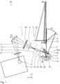
- An illumination optics 1 is a component of an optical system 2 of a mask inspection system 2a for use with EUV illumination light 3.
- a beam path of the illumination light 3 is in the Fig. 1 for the illumination optics 1 via marginal rays and a main beam.
- the illumination light 3 illuminates an illumination field 4 of the mask inspection system.
- the illumination light 3 is generated by an EUV light source 5 into a source region 6.
- the light source 5 can generate useful EUV radiation in a wavelength range between 2 nm and 30 nm, for example in the range between 2.3 nm and 4.4 nm or in the range between 5 nm and 30 nm, for example at 13.5 nm.
- Light source 5 is designed as a plasma light source. This can be, for example, a laser plasma source (LPP; laser produced plasma) or a discharge source (DPP; discharge produced plasma). Such plasma sources are known in principle as light sources for EUV projection exposure systems. Alternatively, light source 5 can also be designed as a high-harmonic EUV source. A pulse frequency of light source 5 can be in the kHz range.
- a Cartesian xyz coordinate system is used below.
- the x-axis is perpendicular to the drawing plane of the Figure 1 and runs into it.
- the y-axis runs in the Figure 1 horizontally to the left and the z-axis runs vertically upwards in Figure 1.
- the illumination light 3 After emission by the light source 5, the illumination light 3 first passes through a useful light filter 8, which is arranged in an operating position in the beam path of the illumination light 3 between the source volume 6 and a first ellipsoidal mirror IL1 of the illumination optics 1.
- the useful light filter 8 can be one of a plurality of filters that are stored in the metrology system 2a, for example, in a filter magazine. Another useful light filter can be arranged in a waiting position outside the illumination light beam path of the illumination optics 1.
- the useful light filters 8 can have the same transmission characteristics, whereby a change between the useful light filters can then be made if a degradation of the filter effect of the operating useful light filter 8 is detected.
- the useful light filters can also have different filter characteristics and, for example, transmit different useful light wavelength ranges into the subsequent illumination light beam path or be optimized to filter out different stray light components.
- the useful light filters can be designed in such a way that they filter out pump light carried in the illumination light beam path, in particular, which was used in the generation of useful light in the source volume 6.
- the illumination light 3 After the filter 8 and the mirror IL1, the illumination light 3 first passes through an aperture stop 9 that limits the edge of a beam of the illumination light 3. Subsequently, the illumination light beam 3 is transferred to a beam-homogenizing element 11 of the illumination optics 1.
- the mirror IL1 serves as the coupling optics 10 for coupling the illumination light 3 into the beam-homogenizing element 11.
- the illumination light 3 passes through an opening in a wall of a vacuum chamber VK, which is in the Fig. 1 in the illumination light beam path between the mirror IL1 and the illumination light aperture diaphragm 9.
- the aperture stop 9 limits a numerical aperture of the illumination light beam 3 emitted by the source region 6 to a value of the numerical aperture in the range between 0.02 and 0.2, for example in the range between 0.07 and 0.15 or also in the range between 0.05 and 0.08.
- an aperture-limiting stop can be arranged between the beam homogenizing element 11 and a subsequent optical component of the illumination optics 1, as shown in the Fig. 1 indicated at 9a. It is also possible to arrange such a further aperture stop in the beam path of the illumination light 3 after the beam-homogenizing element 11 between two downstream optical components of the illumination optics 1.
- the ellipsoidal mirror IL1 is used to image the source region 6 of the EUV light source 5 into an entrance opening 12 in an entrance plane 13 of the beam homogenizing element 11.
- a first focal point of the ellipsoidal mirror IL1 is therefore in the source region 6 and a second focal point of the ellipsoidal mirror IL1 is in the entrance opening 12.
- the ellipsoidal mirror IL1 focuses the illumination light beam 3 into the entrance opening 12 in the entrance plane 13 of the beam homogenizing element 11.
- An entrance-side numerical aperture of the illumination light beam 3 upon entry into the entrance opening 12 can be in the range from 0.02 to 0.2, for example in the range of 0.05.
- the angle of incidence of a central principal ray of the illumination light beam 3 on the coupling mirror IL1 can be in the range between 10° and 20°.
- the ellipsoidal mirror IL1 can be a normal incidence (NI) mirror, but can also be designed as a grazing incidence (GI) mirror.
- the inlet opening 12 and an outlet opening 14 of the beam homogenizing element 11 are each square or rectangular with typical dimensions in the range between 0.5 mm and 5 mm and, for example, between 0.5 mm and 2 mm or even between 0.5 mm and 1 mm.
- An aspect ratio of the inlet opening 12 and an equally sized outlet opening 14 of the beam homogenizing element 11 for the illumination light 3 in an exit plane 15 is between 0.5 and 2.
- a typical size of the inlet opening 12 and the outlet opening 14 of the beam homogenizing element 11 is, for example, 0.5 mm x 1.0 mm, 0.75 mm x 0.75 mm, 1.0 mm x 2.0 mm, or 1.5 mm x 2.0 mm.
- the beam homogenizing element 11 can be designed as a hollow waveguide.
- the beam homogenizing element 11 has a typical length perpendicular to the planes 13 and 15, i.e. along a main beam direction of the illumination light 3, in the range between 50 mm and 500 mm, e.g. in the range between 50 mm and 150 mm, in particular in the range between 50 mm and 100 mm.
- An angle between a normal to the entrance plane 13 of the beam homogenizing element 11 and the main beam of the illuminating light beam 3 incident into the entrance opening 12 can be 0° or alternatively can be different from 0° and, for example, in the range between 0° and 1.5°, for example between 0.25° and 0.75° and in particular in the range of 0.5°.
- a ratio of the distance between the inlet plane 13 and the outlet plane 15, and a size or the typical diameter of the inlet opening or the outlet opening 12, 14, is in the range between 50 and 1000 and can, for example, be in the range between 50 and 200.
- An image-side numerical aperture of this image can be in the range from 0.05 to 0.2.
- the output mirror optics 16 has exactly two mirrors, namely mirrors IL2 and IL3.
- the aperture stop described above, which may be used after the beam homogenizing element 11, can be arranged between the beam homogenizing element 11 and the mirror IL2 or between the mirrors IL2 and IL3.
- the output mirror optics 16 is designed in the manner of a Wolter telescope, namely a Wolter optics type I.
- a Wolter optics type I Such Wolter optics are described in JD Mangus, JH Underwood "Optical Design of a Glancing Incidence X-ray Telescope", Applied Optics, Vol. 8, 1969, page 95 , and the references given there.
- a hyperboloid can also be used in such Wolter optics.
- Such a combination of an ellipsoidal mirror with a hyperboloidal mirror also represents a Type I Wolter optic.
- An imaging factor ⁇ 1 of the input coupling mirror optics 10 can be in the range between 0.1 and 50, i.e., it can reduce by a factor of 10 up to a factor of 50.
- An imaging factor ⁇ 2 of the output coupling mirror optics 16 can be in the range between 0.02 and 10, i.e., it can in turn reduce by a factor of 50 up to a factor of 50.
- a product ⁇ 1 , ⁇ 2 of the two imaging factors can be in the range between 0.25 and 10 for the illumination optics 1.
- a reticle 18 to be inspected is arranged in the object plane 17 as the object to be inspected or the mask to be inspected, which is held by a reticle holder 19.
- the reticle holder 19 is mechanically connected to a reticle displacement drive 20, via which the reticle 18 is displaced along an object displacement direction y during a mask inspection. This enables a scanning displacement of the reticle 18 in the object plane 17.
- the illumination field 4 has a typical dimension in the object plane 17 of less than 1.5 mm.
- the extension of the illumination field 4 is 1 mm in the x-direction and 0.5 mm in the y-direction.
- the x/y aspect ratio of the illumination field 4 corresponds to the x/y aspect ratio of the exit opening 14.
- the illumination field 4, or a portion of the illumination field 4, which then represents an object field, is imaged into an image field 21 in an image plane 22 using projection optics 20a.
- the size of the image field 21 can be in the range of 150 mm x 300 mm.
- the shorter image field extension runs along the scanning direction y.
- the projection optics 20a has a magnification ratio of the image of the object or illumination field 4 into the image field 21 of 500. Depending on the design of the projection optics 20a, this magnification ratio can be in the range between 250 and 500.
- the projection optics 20a has numbered mirrors M1, M2, and M3 in the imaging beam path of the projection optics 20a, thus comprising a total of three mirrors. Depending on the design of the projection optics 20a, the number of mirrors may be greater than three. Further designs that can be used instead of the projection optics 20a are described below with reference to Fig. 2 ff. will be explained further.
- an entrance pupil plane EP of the projection optics 20a which lies in the imaging beam path of the illumination or imaging light between the reflecting reticle 18 and the first mirror M1
- This aperture diaphragm 9b can also be used to specify any internal obscuration of the projection optics 20a.
- the mirrors M1 and M2 of the projection optics 20a are designed as NI mirrors with an angle of incidence of the illumination and imaging light 3 of less than 45°.
- the maximum angle of incidence of individual rays of the illumination light 3 on the mirrors M1 and M2 is in the range of 14°.
- the illumination or imaging light 3 strikes the image field 21 with an angle of incidence that is less than 5°.
- the mirror M1 has an edge of a reflection surface which is used to guide the imaging or illumination light 3 along the imaging beam path, which corresponds to the edge of an entrance pupil EP which is defined by the aperture stop 9b.
- At least one of the mirrors M1 and M2 can be designed as an aspherical mirror.
- the projection optics 20a can have one aspherical mirror or two aspherical mirrors.
- the illumination optics 1 of the metrology system 2a has an illumination pupil, defined by the aperture stop 9b, which is adapted to the entrance pupil EP.
- This illumination pupil of the illumination optics 1 can have a boundary shape other than an ellipse, the shape of which has an aspect ratio other than 1.
- the illumination pupil can have an approximately elliptical, an approximately stadium-shaped, or an approximately semicircular boundary shape with a corresponding, have an aspect ratio different from 1.
- the aspect ratio of the illumination pupil can correspond to that of the entrance pupil EP of the imaging optics 20a.
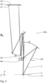
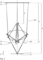
- FIG. 2 and 3 A further embodiment of a projection optics 20b is described below, which can be used instead of the projection optics 20a in the mask inspection system 2a.
- Components and functions that correspond to those described above with reference to the Fig. 1 have already been described, in particular, bear the same reference numbers and will not be discussed again in detail.
- the projection optics 20b has a total of four mirrors M1, M2, M3 and M4 in the imaging beam path between the object or illumination field 4 and the image field 21, which are in turn numbered in the order in which they are exposed to the illumination or imaging light 3.
- the imaging beam path of the projection optics 20b is in the Fig. 2 illustrated by edge rays emanating from two spaced object field points. In the view according to Fig. 3 These are three spaced-apart field points.
- At least one of the mirrors M1 to M4 can be designed as an aspherical mirror.
- the projection optics 20b can have one aspherical mirror, two aspherical mirrors, or even three aspherical mirrors. All four mirrors of the projection optics 20b can also be designed aspherical.
- a boundary shape of an entrance pupil EP of the projection optics 20b which is determined by an inner boundary of the aperture stop 9b, is semicircular and corresponds to the shape of the entrance pupil, which will be described below in connection with the further design of the projection optics from the Fig. 4 and 5 is explained.
- a diameter extension of this semicircular shape of the entrance pupil EP runs parallel to the x-coordinate.
- the entrance pupil EP is bounded by an obscuration accentuated by the mirror M2.
- the x:y aspect ratio of the entrance pupil EP of the projection optics 20b is 2:1. Depending on the design of the projection optics 20b, this aspect ratio can be in the range between 5:1 and 1.1:1.
- the NAx can be between 0.1 and 0.5 and the NAy between 0.05 and 0.25.
- An intermediate image 24 lies between the mirrors M1 and M2 in the imaging beam path of the projection optics 20b.
- mirrors M1 and M2 On the mirrors M1 and M2, individual rays belonging to different field points but with the same illumination angles have a comparatively small distance to each other, which is at most a quarter of a total used reflection surface diameter of the respective mirror.
- a parameter P which characterizes a field or pupil proximity of the respective mirror and is defined in the WO 2009/024164 A1 , for mirrors M1 and M2, the value P is >0.5. Therefore, mirrors M1 and M2 are close to the pupil.
- mirror M1 is a near-pupil mirror.
- the parameter P (cf. again the definition from the WO 2009/024164 A1 ) is less than 0.5 for each of the mirrors M3 and M4. Therefore, the mirrors M3 and M4 are arranged near the field in the imaging beam path of the projection optics 20b.
- the mirror M4 is a near-field mirror.
- the edge of a reflection surface of mirror M1 which is used to guide the imaging light 3 along the imaging beam path, corresponds to the edge of the entrance pupil EP. This approximately also applies to mirror M2.
- the shape of the edge of mirror M2 is mirrored around the xz plane compared to the edge of mirror M1 and also to the edge of the entrance pupil EP.
- a border of a reflection surface of mirror M4, which is used to guide the imaging light 3 along the imaging beam path, corresponds to a border of the image field 21, which is usually rectangular or square. This also applies in a similar way to mirror M3.
- the mirror M4 i.e. the last mirror in the imaging beam path, has a distance A to the image plane 22 which is greater than 60% of a distance B between the object plane 17 and the image plane 22.
- a distance C between the mirrors M4 and M2, i.e. a distance between the last and the third-to-last mirror along a coordinate perpendicular to the image plane 22, is less than 15% of the distance B between the object plane 17 and the image plane 22.
- a distance D between the penultimate mirror M3 in the imaging beam path of the projection optics 20b and the image plane 22 is greater than 20%, greater than 25%, greater than 30% and also greater than 35% of the distance B between the field planes 17, 22.
- the projection optics 20b in turn has a magnification ratio when imaging the object field 4 into the image field 21 in the range between 250 and 500.
- individual rays have an angle of incidence on the mirrors M1 to M4 of a maximum of 13° each.
- the angle of incidence of the individual rays of the imaging light 3 on the image field 21 of the projection optics 20b is a maximum of 5°.
- FIG. 4 and 5 A further embodiment of a projection optics 20c is explained below, which can be used in the mask inspection system 2a instead of the projection optics described above. Components and functions that correspond to those above with reference to the Fig. 1 to 3 have already been described, in particular, bear the same reference numbers and will not be discussed again in detail.
- An imaging beam path of the projection optics 20c basically corresponds to that of the projection optics 20b.
- a distance A between the mirror M4 and the image plane 22 is approximately 69% of the distance B between the object plane 17 and the image plane 22.
- a distance C between the mirrors M4 and M2 is approximately 13% of the distance B.
- the distance D between the penultimate mirror M3 in the imaging beam path and the image plane 22 is approximately 35% of the distance B between the field planes 17, 22.
- the object-field numerical aperture NAx for the 20c projection optics is 0.27.
- the object-field numerical aperture NAy is 0.135.
- the object-field field size is 0.74 mm x 0.28 mm with a field offset of 0.06 mm in y.
- the projection optics 20c has a magnification ratio of 435.
- the distance A in the projection optics 20c is so large that an imperfection on the reflection surface of the mirror M4 with a typical size of 0.16 mm does not lead to the shading of a pixel dimension in the image field 21.
- No single beam within the imaging beam path of the projection optics 20c has an angle of incidence on one of the mirrors M1 to M4 that is greater than 13°.
- the imaging light 3 strikes the image field 21 at the projection optics 20c with an angle of incidence that is less than 5°.
- An RMS wavefront error across the image field 21 for the projection optics 20c is at most 20 m ⁇ , namely 10 m ⁇ in the case of the exemplary embodiment of the projection optics 20c.
- the Petzval radius on the image field side of the projection optics 20c is greater than 500 mm.
- the distortion on the image field side is 1 nm.
- the mirrors M1 and M2 each have a border of a reflection surface, which is used to guide the imaging or illumination light 3 along the imaging beam path, which corresponds to the border of the entrance pupil EP.
- the border shape of the mirror M2 is different from that in the Fig. 5
- the boundary shape of the entrance pupil EP shown is mirrored around the xz plane.
- optical design data of the projection optics 20c are summarized below in Tables 1a/b.
- the first column of Table 1a indicates the respective optical area, starting with object field 4.
- the second column of Table 1a indicates a radius of curvature of the respective optical surface.
- the fourth column of Table 1a indicates a z-distance to the previous surface.
- the fifth column of Table 1a indicates the optical power of the surface, if any. For mirrors M1 to M4, this optical power is "REFL,” meaning reflective.
- the first column of Table 1b shows a maximum value of an incidence height (distance perpendicular to the optical axis) of the respective surface description of the optical surface in mm.
- the second column of Table 1b indicates a maximum deviation of the respective aspheric optical surface from the best-fit sphere, again in mm.
- p is the arrow height
- h is the height of incidence
- r is the radius of curvature
- K is the conic constant and C 1 , C 2 and C 3 are the first three even coefficients of the aspheric correction polynomial.
- Object field 1 Aperture diaphragm 83.5 3: M1 185 0.0150 M2 11.5 0.0007 M3 7.7 0 M4 160 0.009 Image field Mirror K C1 C2 C3 M1 -0.0572 0.000000E+00 0.135E-17 0.779E-23 M2 -0.1520 0.000000E+00 0.360E-10 0.202E-13 M4 -0.6361 0.000E+00 -0.576E-18 0.795E-22
- the mirrors M1, M2, and M4 in the projection optics 20c are therefore designed as aspheres.
- the mirror M3 is a spherical mirror.
- the obscuring effect of mirror M2 with respect to the entrance pupil EP is also highlighted.
- the mirror M2 is designed so that the obscuring OBS does not overlap with the semicircular entrance pupil EP.
- FIG. 6 and 7 A further embodiment of a projection optics 20d is explained below, which can be used in the mask inspection system 2a instead of the projection optics described above. Components and functions that correspond to those described above with reference to the Fig. 1 to 5 have already been described, in particular, bear the same reference numbers and will not be discussed again in detail.
- the object-field numerical aperture NAx for the 20d projection optics is 0.25.
- the object-field numerical aperture NAy is 0.125.
- the object-field field size is 0.56 mm x 0.36 mm with a field offset of 0.06 mm in y.
- the projection optics 20d also has four mirrors M1 to M4.
- a beam path in the projection optics 20d is shown mirrored around the xz plane compared to the beam path of the projection optics 20c. Otherwise, the beam path within the projection optics 20d essentially corresponds to that within the projection optics 20c.
- the distance ratio A to B for the projection optics 20d is: A / B ⁇ 69 %
- the other distance ratios are: C / B ⁇ 10 % D / B ⁇ 20 %
- Fig. 7 shows an edge contour of the entrance pupil EP, which simultaneously corresponds to an inner edge contour of the aperture diaphragm 9b.
- the entrance pupil EP of the projection optics 20d has an edge shape that includes a semicircular edge section 25 and a diameter edge section 26.
- the diameter edge section 26 which together with the semicircular edge section 25 results in an entire edge of the entrance pupil EP, there is a recess section 27 in the edge of the entrance pupil EP.
- a central recess of this recess section 27 runs parallel to the diameter edge section 26, offset from it in the positive y-direction. This central recess of the recess section 27 merges into the diameter edge section 26 via two oblique edge sections 28, 29.
- the y-distance of the central recess section 27 from the diameter boundary section 26 is less than 15% of the y-extension of the entire entrance pupil EP.
- the entire recess in the diameter boundary section thus has a negligible area compared to the semicircular envelope around the entrance pupil EP and also compared to the area of the entrance pupil EP itself.
- the recess section 27 is caused by an obscuration of the entrance pupil EP, which is caused by the mirror M2 of the projection optics 20d.
- the magnification ratio of the projection optics is 20d 435.
- a wavefront error RMS over the image field 21 for the projection optics 20d is 15 m ⁇ .
- the Petzval radius on the image field side of the 20d projection optics is in the range of 20,000 mm.
- optical design data for the projection optics 20d are again summarized in two tables, which correspond in structure to the tables for the Fig. 4 and 5 , i.e. correspond to the projection optics 20c.
- Table 1a/b for Fig. 6/7 Optical surface Radius [mm] Radius of best-fit sphere [mm] Thickness [mm] Effect Object field Infinite 0.000 1: Infinite 196,000 Aperture diaphragm Infinite 0.000 3: Infinite 479.56 M1 527,767 528,588 -459.1 reflective M2 50,000 50,095 584.25 reflective M3 44,030 44.03 -489.63 reflective M4 1263.26 1264,587 688.9 reflective Image field Infinite 0.000000 Optical surface Max.
- Object field 1 Aperture diaphragm 3: M1 170 0.012 M2 10.5 0.0006 M3 7.6 0 M4 180 0.004 Image field Mirror K C1 C2 C3 C4 M1 -0.0584 0.000E+00 0.17E-17 0.666E-23 0 M2 -0.161 0.000E+00 0.438E-10 0.5450E-14 0.642E-17 M4 -0.205 0.000E+00 -3.1 E-18 0.5 E-22 -1E-28
- the aspherical mirrors of the projection optics 20a and also the aspherical mirrors M1, M2, and M4 of the projection optics 20c and 20d have reflection surfaces that deviate from a spherical shape by a maximum of 25 ⁇ m.
- the spherical mirror M3 does not deviate at all from a spherical shape.
- An illumination light beam path of the illumination light 3 for illuminating the reticle 18 and an imaging light beam path of the projection optics 20a for imaging the object field 4 into the image field 21 intersect in an intersection region.
- This intersection region can be located in the area of the entrance pupil plane EP of the projection optics 20a.
- the imaging light beam path intersects with the illumination light beam path between the exit opening 14 and the mirror IL2 of the illumination optics 1, as well as between the mirrors IL2 and IL3 of the illumination optics 1.
- the image field 21 is captured by a detection device 23, e.g., by a CCD camera or several CCD cameras.
- a detection device 23 e.g., by a CCD camera or several CCD cameras.
- the detection device 23 can also be designed as a TDI (time delay integration) detection device with a plurality of TDI detectors.
- the detection device 23 is designed with spatial resolution.
- the detection device 23 can have sensor pixels with a typical pixel size of at most 20 ⁇ m x 20 ⁇ m. This pixel size can be smaller and can be, for example, 15 ⁇ m x 15 ⁇ m or even 10 ⁇ m x 10 ⁇ m.
- a pixel dimension along an image field coordinate x and/or y can be in the range between 1 ⁇ m and 20 ⁇ m.
Landscapes
- Physics & Mathematics (AREA)
- General Physics & Mathematics (AREA)
- Optics & Photonics (AREA)
- Chemical & Material Sciences (AREA)
- Analytical Chemistry (AREA)
- General Health & Medical Sciences (AREA)
- Biochemistry (AREA)
- Life Sciences & Earth Sciences (AREA)
- Immunology (AREA)
- Pathology (AREA)
- Health & Medical Sciences (AREA)
- Lenses (AREA)
- Preparing Plates And Mask In Photomechanical Process (AREA)
Abstract
Eine vergrößernde abbildende Optik (20c) ist Teil eines Metrologiesystems zur Untersuchung von Objekten. Die vergrößernde abbildende Optik hat höchstens vier Spiegel (M1 bis M4), die ein Objektfeld (4) in einer Objektebene (17) in ein Bildfeld (21) in einer Bildebene (22) abbilden. Eine Eintrittspupille der vergrößernden abbildenden Optik hat nach einem Aspekt eine von einer Ellipse abweichende Berandungsform, deren Aspektverhältnis ungleich 1 ist. Reflexionsflächen von Kleinflächen-Spiegeln (M2, M3), die zur Führung von Abbildungslicht (3) längs eines Abbildungsstrahlengangs genutzt werden, weichen gemäß einem weiteren Aspekt von einer sphärischen Form um höchstens 10 µm ab. Es resultiert eine vergrößernde abbildende Optik, bei der bei gegebenen Fertigungsaufwand ein Abbildungsergebnis resultiert, welches die strengen Anforderungen eines Metrologiesystems erfüllt.
Description
- Der Inhalt der deutschen Patentanmeldung
DE 10 2023 213 267.2 wird durch Bezugnahme hierin aufgenommen. - Die Erfindung betrifft eine vergrößernde abbildende Optik für ein Metrologiesystem zur Untersuchung von Objekten. Ferner betrifft die Erfindung eine Beleuchtungsoptik für ein Metrologiesystem, angepasst an eine derartige abbildende Optik, ein optisches System mit einer derartigen abbildenden Optik und einer Beleuchtungsoptik sowie ein Metrologiesystem mit einem derartigen optischen System.
- Ein Maskeninspektionssystem ist bekannt aus der
US 8,842,284 , aus derUS 2013/0250428 A1 , aus derWO 2016/012426 A1 , aus derUS 10,042,248 B2 DE 102 20 815 A1 und aus derWO 2012/101269 A1 . DieDE 10 2010 029 050 A1 und dieDE 10 2011 084 255 A1 offenbaren jeweils eine vergrößernde abbildende Optik sowie ein Metrologiesystem mit einer derartigen abbildenden Optik. DieDE 10 2010 029 049 A1 offenbart ein Beleuchtungssystem für ein Metrologiesystem sowie ein Metrologiesystem mit einer derartigen Beleuchtungsoptik. - Es ist eine Aufgabe der vorliegenden Erfindung, eine vergrößernde abbildende Optik derart weiterzubilden, dass bei gegebenem Fertigungsaufwand gutes Abbildungsergebnis, welches die strengen Anforderungen eines Metrologiesystems erfüllt, resultiert.
- Diese Aufgabe ist erfindungsgemäß gelöst durch eine vergrößernde abbildende Optik nach Anspruch 1.
- Erfindungsgemäß wurde erkannt, dass eine nicht elliptische Eintrittspupille mit einem Aspektverhältnis ungleich 1 zusätzliche Anpassungsmöglichkeiten einer Führung des Abbildungsstrahlengangs innerhalb der vergrößerten abbildenden Optik insbesondere an einen Strahlengang von das Objektfeld beleuchtenden Beleuchtungslicht bietet, was eine Abbildungsqualität und/oder einen Lichtdurchsatz der abbildenden Optik verbessern kann. Die Berandungsform der Eintrittspupille kann angepasst sein an Abbildungsanforderungen, beispielsweise an unterschiedliche typische Objektstrukturgrößen in zwei aufeinander senkrecht stehenden Felddimensionen. Alternativ oder zusätzlich ist eine Anpassung an eine Beugungswirkung der Objektstrukturen und/oder auch an eine Beleuchtungspupille einer Beleuchtungsoptik des Metrologiesystems möglich, die ihrerseits eine Berandungsform mit einem Aspektverhältnis ungleich 1 hat.
- Ein x:y-Aspektverhältnis der Eintrittspupille der vergrößernden abbildenden Optik kann im Bereich zwischen 1,1: 1 und 5:1 liegen, wobei die x-Koordinate dabei senkrecht auf einer Meridionalebene der vergrößernden abbildenden Optik liegen kann. Das x:y-Aspektverhältnis kann beispielsweise 2:1 sein.
- Eine kleinste sich hierbei ergebende objektseitige numerische Apertur der vergrößernden abbildenden Optik kann größer sein als 0,1, kann größer sein als 0,12 und kann beispielsweise 0,125 oder auch 0,135 betragen.
- Eine Berandungsform der Eintrittspupille nach Anspruch 2 kann gut an bauliche Anforderungen und insbesondere an räumliche Anforderungen des Abbildungsstrahlengangs angepasst sein. Ein entsprechend hoher Lichtdurchsatz ist die Folge.
- Entsprechendes gilt für eine Eintrittspupille mit einem Aussparungsabschnitt nach Anspruch 3. Der Aussparungsabschnitt kann einer Obskuration durch mindestens einen Spiegel der vergrößernden abbildenden Optik Rechnung tragen.
- Bei einer Ausgestaltung nach Anspruch 4 kommen Vorteile einer Eintrittspupille mit einem Aspektverhältnis ungleich 1 besonders gut zu tragen. Der mindestens eine Spiegel, dessen Berandung derjenigen der Eintrittspupille entspricht, kann ein pupillennaher Spiegel sein. Es kann sich hierbei um den ersten und gegebenenfalls auch um den zweiten Spiegel der vergrößernden abbildenden Optik handeln.
- Die Ausgestaltung nach Anspruch 5 schafft die Möglichkeit, ohne unerwünschte Abstriche an einer Abbildungsqualität die vergrößernde abbildende Optik mit Kleinflächen-Spiegeln auszuführen, die nur gering oder auch gar nicht von einer sphärischen Form abweichen. Dies erleichtert eine Herstellung der Kleinflächen-Spiegel der vergrößernden abbildenden Optik und bietet entsprechende Fertigungsvorteile.
- Die Abweichung der Reflexionsflächen von einer sphärischen Form wird gemessen in Bezug auf eine sphärische Form, die an die jeweilige Spiegel-Reflexionsfläche bestangepasst ist. Eine derartige beste Anpassung kann durch Minimierung eines Fehlerquadrats beim Vergleich der jeweiligen Reflexionsfläche mit einer sphärischen Fläche ermittelt werden.
- Die Abweichung der Reflexionsfläche des jeweiligen Kleinflächen-Spiegels von der sphärischen Form kann höchstens 5µm sein, oder kann auch höchstens 1 µm sein. Bei einer derart geringen Abweichung ist eine Bearbeitung bei der Spiegelherstellung mit einer geringen Anzahl von Bearbeitungszyklen möglich. Der Kleinflächen-Spiegel kann als Nanoasphäre ausgeführt sein, bei dem eine Abweichung der Reflexionsfläche von einer sphärischen Form höchstens das Zehnfache der Nutzwellenlänge beträgt. Eine solche Nanoasphäre kann mit einer Messtechnik vermessen werden, die zur Vermessung einer sphärischen Reflexionsfläche ausgelegt ist.
- Zwischen einem ersten und einem zweiten Spiegel im Abbildungsstrahlengang der vergrößernden abbildenden Optik kann ein Zwischenbild liegen. Es kann zur Verbesserung einer abbildungsfehlerkorrigierenden Wirkung genutzt werden. Zudem kann dies dazu genutzt werden, einen insbesondere kompakten Strahlangang im Bereich von den zwischenfokusnah beziehungsweise feldnah angeordneten Spiegeln zu schaffen.
- Zur Charakterisierung einer derartigen Eigenschaft "feldnah" kann ein Parameter P herangezogen werden, der definiert ist in der
WO 2009/024164 A1 . Als feldnah gilt ein Spiegel dann, wenn der Parameter P kleiner ist als 0,5 und insbesondere kleiner ist als 0,4, kleiner als 0,3, kleiner als 0,25 oder auch kleiner als 0,2. Regelmäßig ist dieser Parameter P bei realen Spiegeln größer als 0,05. - Ein letzter Spiegel der vergrößernden abbildenden Optik im Abbildungsstrahlengang kann feldnah ausgeführt sein.
- Ein erster und gegebenenfalls auch ein zweiter Spiegel im Abbildungsstrahlengang der vergrößernden abbildenden Optik kann pupillennah ausgeführt sein. Der Parameter P ist bei diesen pupillennahen Spiegeln größer als 0,5, kann größer sein als 0,6, kann größer sein als 0,7 und kann auch größer sein als 0,8. Regelmäßig ist bei einem realen pupillennahen Spiegel der Parameter P kleiner als 0,95.
- Die vergrößernde abbildende Optik kann zur Nutzung mit EUV-Abbildungslicht insbesondere mit einer Wellenlänge ausgelegt sein, die im Bereich zwischen 5 nm und 30 nm liegt, beispielsweise 13,5 nm beträgt. Die vergrößernde abbildende Optik kann insbesondere für entsprechende EUV-Wellenlängen ausgeführte hochreflektierende Beschichtungen aufweisen.
- Eine Baulänge der vergrößernden abbildenden Optik kann höchstens 1250 mm betragen, was zu einer kompakten Optik führt.
- Die Spiegel der vergrößerten abbildenden Optik können so ausgeführt sein, dass keiner der Spiegel einen Durchmesser einer zur Führung des Abbildungslichts längs des Abbildungsstrahlengangs genutzten Reflexionsfläche aufweist, der größer ist als 400 mm. Auch dies führt zu einer kompakten Optik.
- Bei einer Ausführung nach Anspruch 6 weichen die Reflexionsflächen aller Spiegel nur gering, nämlich um höchstens 25 µm, von einer sphärischen Form ab, also auch von Spiegeln mit einem Durchmesser, der mindestens 50 mm beträgt, die nachfolgend auch als Großflächen-Spiegel bezeichnet werden. Es resultieren entsprechende Fertigungsvorteile für alle Spiegel der vergrößernden abbildenden Optik. Die Abweichung der Reflexionsflächenspiegel von der sphärischen Form kann höchstens 20 µm betragen, höchstens 15 µm oder kann auch für alle Spiegel so groß sein, wie vorstehend im Zusammenhang mit dem mindestens einen Kleinflächenspiegel diskutiert.
- Abstandsverhältnisse nach Anspruch 7 führen dazu, dass Imperfektionen und/oder Kontaminationen auf dem letzten Spiegel im Abbildungsstrahlengang der vergrößernden abbildenden Optik keine unerwünschten Auswirkungen auf eine Abbildungsqualität der Optik haben. Dies gilt insbesondere dann, wenn der letzte Spiegel als feldnaher Spiegel ausgeführt ist. Der Abstand des letzten Spiegels zur Bildebene kann größer sein als 65% eines Abstandes zwischen der Objektebene und der Bildebene. Regelmäßig ist dieser Abstand kleiner als der Abstand zwischen der Objektebene und der Bildebene.
- Ein Abstand zwischen dem letzten und einem drittletzten Spiegel im Abbildungsstrahlengang der vergrößernden abbildenden Optik längs einer Koordinate senkrecht zur Bildebene kann, eine entsprechende Ausführung der vergrößernden abbildenden Optik vorausgesetzt, kleiner sein als 15%, kleiner als 12% oder auch kleiner sein als 10% des Abstandes zwischen der Objektebene und der Bildebene. Dieser Abstand zwischen dem letzten und dem drittletzten Spiegel ist regelmäßig größer als 1% des Abstandes zwischen der Objektebene und der Bildebene.
- Ein Vergrößerungsverhältnis nach Anspruch 8 hat sich in der Praxis bewährt. Ein derartiges Vergrößerungsverhältnis kann an Pixelgrößen einer das Bildfeld erfassenden, ortsauflösenden Detektionseinrichtung des Metrologiesystems angepasst sein.
- Die vergrößernde abbildende Optik kann ein Objektfeld mit einer Erstreckung in den beiden Objektfeld-Dimensionen im Bereich jeweils zwischen 0,1 mm und 1 mm haben und kann eine Fläche von beispielsweise 0,1 mm2 bis 0,5 mm2 haben. Eine typische Objektfelderstreckung ist 0,3 mm x 0,6 mm oder auch 0,5 mm x 0,5 mm.
- Einfallswinkel nach den Ansprüchen 9 und 10 haben sich in der Praxis bewährt und führen zu günstigen Reflexionsbedingungen beziehungsweise zu guten Abbildungsverhältnissen. Ein Einfallswinkel auf den Spiegeln kann jeweils höchstens 13° betragen oder auch noch kleiner sein.
- Ein RMS-Wellenfrontfehler nach Anspruch 11 führt zu einer guten Abbildungsqualität. Ein bildfeldseitiger Petzvalradius der vergrößernden abbildenden Optik kann größer sein als 500 mm.
- Ein Mindestwert für eine Abweichung einer Spiegel-Reflexionsfläche von einer sphärischen Form nach Anspruch 12 hat sich in der Praxis bewährt. Bei einer Nutzwellenlänge von 13,5 nm entspricht dies einer Mindestabweichung, also einer Abweichungs-Untergrenze, von 25 nm. Je nach Ausführung der vergrößernden abbildenden Optik können mehrere, zum Beispiel zwei oder drei, Spiegel dieses Kriterium der Abweichungs-Untergrenze erfüllen oder auch genau einer der Spiegel. Bei einer weiteren Ausführung erfüllen alle Spiegel der vergrößernden abbildenden Optik diese Abweichungs-Untergrenze des Doppelten der Nutzwellenlänge.
- Die Vorteile einer Beleuchtungsoptik nach Anspruch 13 entsprechen denen, die vorstehend in Zusammenhang mit den verschiedenen Aspekten der vergrößernden abbildenden Optik bereits erläutert wurden.
- Eine Berandungsform der Beleuchtungspupille kann zumindest angenähert elliptisch sein, kann zumindest angenähert stadionförmig sein und kann auch zumindest angenähert halbkreisförmig sein.
- Die Vorteile eines optischen Systems nach Anspruch 14 oder 15 und eines Metrologiesystems nach Anspruch 16 entsprechen denen, die vorstehend unter Bezugnahme auf die vergrößernde abbildende Optik und die Beleuchtungsoptik bereits erläutert wurden.
- Bei der Lichtquelle des Metrologiesystems kann es sich um eine EUV-Lichtquelle handeln.
- Die Detektionseinrichtung kann mindestens eine TDI-Kamera aufweisen.
- Das Metrologiesystem kann als Maskeninspektionssystem oder auch als Waferinspektionssystem ausgeführt sein.
- Das Inspektionssystem kann einen Objekthalter zur Halterung des zu inspizierenden Objektes aufweisen, der mit einem Objektverlagerungsantrieb mechanisch gekoppelt ist, so dass eine scannende Verlagerung des Objekts bei der Beleuchtung möglich ist.
- Beim Inspektionssystem kann es sich um ein System für die aktinische Masken- bzw. Waferinspektion handeln.
- Ein Ausführungsbeispiel der Erfindung wird nachfolgend anhand der Zeichnung näher erläutert. In dieser zeigen:
- Fig. 1
- schematisch in einem Meridionalschnitt ein Maskeninspektionssystem für Lithographiemasken zum Einsatz mit EUV-Beleuchtungslicht, mit einem Beleuchtungssystem, aufweisend eine Energie-Detektions-Baugruppe mit einem strahlhomogenisierenden Element, mit einer abbildenden Optik und mit mindestens einer EUV-Energiesensor-Einrichtung;
- Fig. 2
- in einem Meridionalschnitt eine schematische Ansicht einer weiteren Ausführung einer abbildenden Optik, die anstelle der abbildenden Optik nach
Fig. 1 beim Maskeninspektionssystem zum Einsatz kommen kann; - Fig. 3
- Eine schematische Ansicht der abbildenden Optik aus Blickrichtung III in
Fig. 2 ; - Fig. 4
- in einem Meridionalschnitt eine weitere Ausführung einer abbildenden Optik, die anstelle der abbildenden Optik nach
Fig. 1 beim Maskeninspektionssystem zum Einsatz kommen kann; - Fig. 5
- in Pupillenkoordinaten eine Eintrittspupille der abbildenden Optik nach
Fig. 4 ; - Fig. 6
- in einem Meridionalschnitt eine Ausführung einer abbildenden Optik, die anstelle der abbildenden Optik nach
Fig. 1 beim Maskeninspektionssystem zum Einsatz kommen kann; und - Fig. 7
- in Pupillenkoordinaten eine Eintrittspupille der abbildenden Optik nach
Fig. 6 . - Eine Beleuchtungsoptik 1 ist Bestandteil eines optischen Systems 2 eines Maskeninspektionssystems 2a zum Einsatz mit EUV-Beleuchtungslicht 3. Ein Strahlengang des Beleuchtungslichts 3 ist in der
Fig. 1 für die Beleuchtungsoptik 1 über Randstrahlen und einen Hauptstrahl veranschaulicht. Beleuchtet wird mit dem Beleuchtungslicht 3 ein Beleuchtungsfeld 4 des Maskeninspektionssystems. - Das Beleuchtungslicht 3 wird von einer EUV-Lichtquelle 5 in einen Quellbereich 6 erzeugt. Die Lichtquelle 5 kann EUV-Nutzstrahlung in einem Wellenlängenbereich zwischen 2 nm und 30 nm, beispielsweise im Bereich zwischen 2,3 nm und 4,4 nm oder im Bereich zwischen 5 nm und 30 nm, beispielsweise bei 13,5 nm, erzeugen.
- Die Lichtquelle 5 ist als Plasma-Lichtquelle ausgeführt. Es kann sich hierbei beispielsweise um eine Laser-Plasma-Quelle (LPP; laser produced plasma) oder auch um eine Entladungsquelle (DPP; discharge produced plasma) handeln. Derartige Plasma-Quellen sind als Lichtquellen für EUV-Projektionsbelichtungsanlagen im Prinzip bekannt. Alternativ kann die Lichtquelle 5 auch als High-Harmonic EUV-Quelle ausgeführt sein. Eine Pulsfrequenz der Lichtquelle 5 kann im kHz-Bereich liegen.
- Zur Erleichterung von Lagebeziehungen wird nachfolgend ein kartesisches xyz-Koordinatensystem verwendet. Die x-Achse steht senkrecht auf der Zeichenebene der
Figur 1 und verläuft in diese hinein. Die y-Achse verläuft in derFigur 1 horizontal nach links und die z-Achse verläuft in der Figur 1 vertikal nach oben. - Nach Emission durch die Lichtquelle 5 passiert das Beleuchtungslicht 3 zunächst einen Nutzlicht-Filter 8, der in einer Betriebsposition im Strahlengang des Beleuchtungslichts 3 zwischen dem Quellvolumen 6 und einem ersten Ellipsoid-Spiegel IL1 der Beleuchtungsoptik 1 angeordnet ist. Der Nutzlicht-Filter 8 kann ein Filter einer Mehrzahl von Filtern sein, die beim Metrologiesystem 2a beispielsweise in einem Filtermagazin vorgehalten werden. Ein weiterer Nutzlicht-Filter kann in einer Warteposition außerhalb des Beleuchtungslicht-Strahlengangs der Beleuchtungsoptik 1 angeordnet sein. Die Nutzlicht-Filter 8 können die gleiche Transmissionscharakteristik aufweisen, wobei dann ein Wechsel zwischen den Nutzlicht-Filtern vorgenommen werden kann, wenn eine Degradation einer Filterwirkung des Betriebs-Nutzlicht-Filters 8 festgestellt ist. Alternativ können die Nutzlicht-Filter auch unterschiedliche Filtercharakteristiken aufweisen und beispielsweise verschiedene Nutzlicht-Wellenlängenbereiche in den nachfolgenden Beleuchtungslicht-Strahlengang durchlassen bzw. zur Herausfilterung unterschiedlicher Falschlicht-Anteile optimiert sein.
- Die Nutzlicht-Filter können derart ausgebildet sein, dass sie insbesondere im Beleuchtungslicht-Strahlengang mitgeführtes Pumplicht, das bei der Nutzlichterzeugung im Quellvolumen 6 genutzt wurde, herausfiltern.
- Nach dem Filter 8 und dem Spiegel IL1 durchtritt das Beleuchtungslicht 3 zunächst eine ein Bündel des Beleuchtungslichts 3 randseitig begrenzende Aperturblende 9. Im Anschluss hieran wird das Beleuchtungslicht-Bündel 3 hin zu einem strahlhomogenisierenden Element 11 der Beleuchtungsoptik 1 überführt. Der Spiegel IL1 dient dabei als Einkoppeloptik 10 zur Einkopplung des Beleuchtungslichts 3 in das strahlhomogenisierende Element 11.
- Zwischen dem Quellvolumen 6 und dem strahlhomogenisierenden Element 11, im Regelfall nach dem ersten Spiegel IL1 der Beleuchtungsoptik 1, passiert das Beleuchtungslicht 3 eine Öffnung in einer Wand einer Vakuumkammer VK, die in der
Fig. 1 im Beleuchtungslicht-Strahlengang zwischen dem Spiegel IL1 und der Beleuchtungslicht-Aperturblende 9 angedeutet ist. - Die Aperturblende 9 begrenzt eine numerische Apertur des vom Quellbereich 6 emittierten Beleuchtungslicht-Bündels 3 auf einen Wert der numerischen Apertur im Bereich zwischen 0,02 und 0,2, beispielsweise im Bereich zwischen 0,07 und 0,15 oder auch im Bereich zwischen 0,05 und 0,08. Alternativ oder zusätzlich zur Aperturblende 9 kann eine aperturbegrenzende Blende zwischen dem strahlhomogenisierenden Element 11 und einer nachfolgenden optischen Komponente der Beleuchtungsoptik 1 angeordnet sein, wie in der
Fig. 1 bei 9a angedeutet. Auch eine Anordnung einer derartigen weiteren Aperturblende im Strahlengang des Beleuchtungslichts 3 nach dem strahlhomogenisierenden Element 11 zwischen zwei nachgeordneten optischen Komponenten der Beleuchtungsoptik 1 ist möglich. - Der Ellipsoid-Spiegel IL1 dient zur Abbildung des Quellbereichs 6 der EUV-Lichtquelle 5 in eine Eintrittsöffnung 12 in einer Eintrittsebene 13 des strahlhomogenisierenden Elements 11. Ein erster Brennpunkt des Ellipsoid-Spiegels IL1 liegt also im Quellbereich 6 und ein zweiter Brennpunkt des Ellipsoid-Spiegels IL1 in der Eintrittsöffnung 12. Mit dem Ellipsoid-Spiegel IL1 wird das Beleuchtungslicht-Bündel 3 in die Eintrittsöffnung 12 in der Eintrittsebene 13 des strahlhomogenisierenden Elements 11 fokussiert. Eine eintrittsseitige numerische Apertur des Beleuchtungslicht-Bündels 3 beim Eintritt in die Eintrittsöffnung 12 kann im Bereich von 0,02 bis 0,2, beispielsweise im Bereich von 0,05 liegen.
- Ein Einfallswinkel eines zentralen Hauptstrahls des Beleuchtungslicht-Bündels 3 auf dem Einkoppel-Spiegel IL1 kann im Bereich zwischen 10° und 20° liegen. Der Ellipsoid-Spiegel IL1 kann ein Spiegel für normalen Einfall (Normal Incidence, NI) sein, kann aber auch als Spiegel mit streifendem Einfall (Grazing Incidence, GI) ausgeführt sein.
- Die Eintrittsöffnung 12 und eine Austrittsöffnung 14 des strahlhomogenisierenden Elements 11 sind jeweils quadratisch oder rechteckig mit typischen Dimensionen im Bereich zwischen 0,5 mm und 5 mm und beispielsweise zwischen 0,5 mm und 2 mm oder auch zwischen 0,5 mm und 1 mm. Ein Aspektverhältnis der Eintrittsöffnung 12 und einer gleichgroßen Austrittsöffnung 14 des strahlhomogenisierenden Elements 11 für das Beleuchtungslicht 3 in einer Austrittsebene 15 liegt zwischen 0,5 und 2. Eine typische Größe der Eintrittsöffnung 12 und der Austrittsöffnung 14 des strahlhomogenisierenden Elements 11 beträgt z.B. 0,5 mm x 1,0 mm, 0,75 mm x 0,75 mm, 1,0 mm x 2,0 mm oder 1,5 mm x 2,0 mm.
- Das strahlhomogenisierende Element 11 kann als Hohlwellenleiter ausgeführt sein.
- Das strahlhomogenisierende Element 11 hat eine typische Länge senkrecht zu den Ebenen 13 und 15, also längs einer Haupt-Strahlrichtung des Beleuchtungslichts 3, im Bereich zwischen 50 mm und 500 mm, z. B. im Bereich zwischen 50 mm und 150 mm, insbesondere im Bereich zwischen 50 mm und 100 mm.
- Ein Winkel zwischen einer Normalen auf die Eintrittsebene 13 des strahlhomogenisierenden Elements 11 und dem in die Eintrittsöffnung 12 einfallenden Hauptstrahl des Beleuchtungslicht-Bündels 3 kann bei 0° liegen oder kann alternativ auch von 0° verschieden sein und beispielsweise im Beriech zwischen 0° und 1,5°, beispielsweise zwischen 0,25° und 0,75° und insbesondere im Bereich von 0,5° liegen.
- Ein Verhältnis aus dem Abstandes zwischen der Eintrittsebene 13 und der Austrittsebene 15, und einer Größe bzw. dem typischen Durchmesser der Eintrittsöffnung bzw. der Austrittsöffnung 12, 14, liegt im Bereich zwischen 50 und 1000 und kann beispielsweise im Bereich zwischen 50 und 200 liegen.
- Eine dem strahlhomogenisierenden Element 11 nachgeordnete abbildende Auskoppel-Spiegeloptik 16 mit zwei Spiegeln IL2, IL3 bildet die in einer Austrittsebene 15 liegende Austrittsöffnung 14 des strahlhomogenisierenden Elements 11 in das Beleuchtungsfeld 4 in einer Objektebene 17 ab. Eine bildseitige numerische Apertur dieser Abbildung kann im Bereich von 0.05 bis 0.2 liegen.
- Bei der dargestellten Ausführung hat die Auskoppel-Spiegeloptik 16 genau zwei Spiegel, nämlich die Spiegel IL2 und IL3. Die vorstehend erläuterte, gegebenenfalls zum Einsatz kommende Aperturblende nach dem strahlhomogenisierenden Element 11 kann zwischen dem strahlhomogenisierenden Element 11 und dem Spiegel IL2 oder auch zwischen den Spiegeln IL2 und IL3 angeordnet sein.
- Die Auskoppel-Spiegeloptik 16 ist nach Art eines Wolter-Teleskops, nämlich nach Art einer Wolter-Optik Typ I, ausgeführt. Derartige Wolter-Optiken sind beschrieben in J. D. Mangus, J. H. Underwood "Optical Design of a Glancing Incidence X-ray Telescope", Applied Optics, Vol. 8, 1969, Seite 95, und den dort angegebenen Referenzen. Anstelle eines Paraboloids kann bei derartigen Wolter-Optiken auch ein Hyperboloid eingesetzt werden. Auch eine solche Kombination eines Ellipsoid-Spiegels mit einem Hyperboloid-Spiegel stellt eine Wolter-Optik vom Typ I dar.
- Ein Ausführungsbeispiel für die Auskoppel-Spiegeloptik 16 ist beschrieben in der
US 10,042,248 B2 - Ein Abbildungsfaktor β1 der Einkoppel-Spiegeloptik 10 kann im Bereich zwischen 0,1 und 50 liegen, kann also um einen Faktor 10 verkleinernd bis hin zu einem Faktor 50 vergrößernd wirken. Ein Abbildungsfaktor β2 der Auskoppel-Spiegeloptik 16 kann im Bereich zwischen 0,02 und 10 liegen, kann also seinerseits wiederum um einen Faktor 50 verkleinern bis hin zu einem Faktor vergrößern. Ein Produkt β1, β2 der beiden Abbildungsfaktoren kann bei der Beleuchtungsoptik 1 im Bereich zwischen 0,25 und 10 liegen.
- In der Objektebene 17 ist ein zu inspizierendes Retikel 18 als zu inspizierendes Objekt bzw. zu inspizierende Maske angeordnet, das von einem Retikelhalter 19 gehalten ist. Der Retikelhalter 19 steht mit einem Retikelverlagerungsantrieb 20 in mechanischer Wirkverbindung, über den das Retikel 18 längs einer Objektverlagerungsrichtung y während einer Maskeninspektion verlagert wird. Hierüber ist eine scannende Verlagerung des Retikels 18 in der Objektebene 17 möglich.
- Das Beleuchtungsfeld 4 hat eine typische Dimension in der Objektebene 17, die kleiner ist als 1.5 mm. Die Erstreckung des Beleuchtungsfeldes 4 beträgt bei der dargestellten Ausführung 1 mm in der x-Richtung und 0,5 mm in der y-Richtung.
- Das x/y-Aspektverhältnis des Beleuchtungsfelds 4 stimmt mit dem x/y-Aspektverhältnis der Austrittsöffnung 14 überein.
- Das Beleuchtungsfeld 4 bzw. ein Teil des Beleuchtungsfelds 4, der dann ein Objektfeld darstellt, wird mit einer Projektionsoptik 20a in ein Bildfeld 21 in einer Bildebene 22 abgebildet. Eine Größe des Bildfeldes 21 kann im Bereich von 150 mm x 300 mm liegen. Die kürzere Bildfeld-Erstreckung verläuft längs der Scanrichtung y.
- Die Projektionsoptik 20a hat ein Vergrößerungsverhältnis der Abbildung des Objekt- beziehungsweise Beleuchtungsfeldes 4 in das Bildfeld 21 von 500. Je nach Ausführung der Projektionsoptik 20a kann dieses Vergrößerungsverhältnis im Bereich zwischen 250 und 500 liegen.
- Die Projektionsoptik 20a hat im Abbildungs-Strahlengang der Projektionsoptik 20a durchnummerierte Spiegel M1, M2, M3 weist also insgesamt drei Spiegel auf. Je nach Ausführung der Projektionsoptik 20a kann die Anzahl der Spiegel auch größer sein als drei. Weitere Ausführungen, die anstelle der Projektionsoptik 20a zum Einsatz kommen können, werden nachfolgend anhand der
Fig. 2 ff. noch erläutert. - In einer Eintritts-Pupillenebene EP der Projektionsoptik 20a, die im Abbildungs-Strahlengang des Beleuchtungs- bzw. Abbildungslichts zwischen dem reflektierenden Retikel 18 und dem ersten Spiegel M1 liegt, ist eine Aperturblende 9b angeordnet. Diese Aperturblende 9b kann auch zur Vorgabe einer gegebenenfalls vorliegenden inneren Obskuration der Projektionsoptik 20a dienen.
- Die Spiegel M1 und M2 der Projektionsoptik 20a sind als NI-Spiegel mit einem Einfallswinkel des Beleuchtungs- und Abbildungslichts 3 von weniger als 45° ausgeführt. Ein maximaler Einfallswinkel von Einzelstrahlen des Beleuchtungslichts 3 auf den Spiegeln M1 und M2 liegt im Bereich von 14°.
- Das Beleuchtungs- beziehungsweise Abbildungslicht 3 trifft auf das Bildfeld 21 mit einem Einfallswinkel auf, der kleiner ist als 5°.
- Der Spiegel M1 hat eine Berandung einer Reflexionsfläche, die zur Führung des Abbildungs- beziehungsweise Beleuchtungslichts 3 längs des Abbildungsstrahlengangs genutzt wird, die der Berandung einer Eintrittspupille EP, die von der Aperturblende 9b vorgegeben wird, entspricht.
- Mindestens einer der Spiegel M1 und M2 kann als asphärischer Spiegel ausgeführt sein. Die Projektionsoptik 20a kann einen asphärischen Spiegel oder kann zwei asphärische Spiegel aufweisen.
- Die Beleuchtungsoptik 1 des Metrologiesystems 2a hat ihrerseits eine Beleuchtungspupille, vorgegeben über die Aperturblende 9b, die an die Eintrittspupille EP angepasst ist. Diese Beleuchtungspupille der Beleuchtungsoptik 1 kann eine von einer Ellipse abweichende Berandungsform aufweisen, deren Aspektverhältnis ungleich 1 ist. Die Beleuchtungspupille kann eine angenähert elliptische, eine angenähert stadionförmige oder auch eine angenähert halbkreisförmige Berandungsform mit einem entsprechenden, von 1 abweichenden Aspektverhältnis aufweisen. Das Aspektverhältnis der Beleuchtungspupille kann demjenigen der Eintrittspupille EP der abbildenden Optik 20a entsprechen.
- Anhand der
Fig. 2 und3 wird nachfolgend eine weitere Ausführung einer Projektionsoptik 20b beschrieben, die anstelle der Projektionsoptik 20a beim Maskeninspektionssystem 2a zum Einsatz kommen kann. Komponenten und Funktionen, die denjenigen entsprechen, die vorstehend unter Bezugnahme auf dieFig. 1 bereits beschrieben wurden, tragen insbesondere die gleichen Bezugsziffern und werden nicht nochmals im Einzelnen diskutiert. - Die Projektionsoptik 20b hat im Abbildungsstrahlengang zwischen dem Objekt- beziehungsweise Beleuchtungsfeld 4 und dem Bildfeld 21 insgesamt 4 Spiegel M1, M2, M3 und M4, die wiederum in der Reihenfolge ihrer Beaufschlagung mit dem Beleuchtungs- beziehungsweise Abbildungslicht 3 durchnummeriert sind. Der Abbildungsstrahlengang der Projektionsoptik 20b ist in der
Fig. 2 durch Randstrahlen veranschaulicht, die von zwei zueinander beabstandeten Objekt-Feldpunkten ausgehen. In der Ansicht nachFig. 3 sind dies drei voneinander beabstandete Feldpunkte. - Mindestens einer der Spiegel M1 bis M4 kann als asphärischer Spiegel ausgeführt sein. Die Projektionsoptik 20b kann einen asphärischen Spiegel, kann zwei asphärische Spiegel oder auch drei asphärische Spiegel aufweisen. Auch alle vier Spiegel der Projektionsoptik 20b können asphärisch ausgeführt sein.
- Zwischen dem Objektfeld 4 und dem Spiegel M1 liegt eine Eintrittspupillenebene, in der die Aperturblende 9b angeordnet ist.
- Eine Berandungsform einer Eintrittspupille EP der Projektionsoptik 20b, die von einer inneren Berandung der Aperturblende 9b vorgegeben wird, ist halbkreisförmig und entspricht der Form der Eintrittspupille, die nachfolgend noch im Zusammenhang mit der weiteren Ausführung der Projektionsoptiken aus den
Fig. 4 und5 erläutert wird. - Eine Durchmessererstreckung dieser Halbkreisform der Eintrittspupille EP verläuft parallel zur x-Koordinate. Im Bereich eines entsprechenden, längs der x-Koordinate verlaufenden Durchmesser-Berandungsschnittes der Eintrittspupille EP wird die Eintrittspupille EP begrenzt von einer durch den Spiegel M2 hervorgehobenen Obskuration.
- Ein x:y-Aspektverhältnis der Eintrittspupille EP beträgt bei der Projektionsoptik 20b 2:1. Je nach Ausführung der Projektionsoptik 20b kann dieses Aspektverhältnis im Bereich zwischen 5: 1 und 1,1:1 liegen. Eine objektseitige numerische Apertur der Projektionsoptik 20b liegt in der yz-Ebene nach
Fig. 2 bei etwa 0,125 (NAy=0,125) und in der hierzu senkrechten xz-Ebene bei etwa 0,25 (NAx=0,25). Je nach Ausführung der Projektionsoptik 20b kann die NAx zwischen 0,1 und 0,5 liegen und die NAy zwischen 0,05 und 0,25. - Zwischen den Spiegeln M1 und M2 liegt im Abbildungsstrahlengang der Projektionsoptik 20b ein Zwischenbild 24.
- Auf den Spiegeln M1 und M2 haben Einzelstrahlen, die zu verschiedenen Feldpunkten, aber gleichen Beleuchtungswinkeln gehören, einen vergleichsweise geringen Abstand zueinander, der höchstens ein Viertel eines gesamten genutzten Reflexionsflächendurchmessers des jeweiligen Spiegels beträgt. Ein Parameter P, der eine Feld- beziehungsweise Pupillennähe des jeweiligen Spiegels charakterisiert und definiert ist in der
WO 2009/024164 A1 , liegt bei den Spiegeln M1 und M2 jeweils bei einem Wert von P>0,5. Die Spiegel M1 und M2 sind daher pupillennah. Insbesondere ist der Spiegel M1 ein pupillennaher Spiegel. - Auf den Spiegeln M3 und M4 haben Einzelstrahlen, die zu gleichen Feldpunkten, aber unterschiedlichen Beleuchtungswinkeln gehören, wiederum einen Abstand zueinander, der höchstens ein Viertel eines gesamten genutzten Reflexionsflächendurchmessers des jeweiligen Spiegels beträgt der Parameter P (vgl. wiederum die Definition aus der
WO 2009/024164 A1 ) ist bei den Spiegeln M3 und M4 jeweils kleiner als 0,5. Die Spiegel M3 und M4 sind daher im Abbildungsstrahlengang der Projektionsoptik 20b feldnah angeordnete Spiegel. Insbesondere ist der Spiegel M4 ein feldnaher Spiegel. - Eine Berandung einer Reflexionsfläche des Spiegels M1, die zur Führung des Abbildungslichts 3 längs des Abbildungsstrahlengangs genutzt wird, entspricht der Berandung der Eintrittspupille EP. Dies gilt näherungsweise auch für den Spiegel M2. Eine Berandungsform ist beim Spiegel M2 im Vergleich zur Berandung des Spiegels M1 und auch zur Berandung der Eintrittspupille EP um die xz-Ebene gespiegelt.
- Eine Berandung einer Reflexionsfläche des Spiegels M4, die zur Führung des Abbildungslichts 3 längs des Abbildungsstrahlengangs genutzt wird, entspricht einer Berandung des Bildfeldes 21, die regelmäßig rechteckig oder quadratisch ausgeführt ist. In ähnlicher Form gilt dies auch für den Spiegel M3.
- Der Spiegel M4, also der im Abbildungsstrahlengang letzte Spiegel, hat einen Abstand A zur Bildebene 22, der größer als 60% eines Abstandes B zwischen der Objektebene 17 und der Bildebene 22 ist.
- Ein Abstand C zwischen den Spiegeln M4 und M2, also ein Abstand zwischen dem letzten und dem drittletzten Spiegel längs einer Koordinate senkrecht zur Bildebene 22, ist kleiner als 15% des Abstandes B zwischen der Objektebene 17 und der Bildebene 22.
- Ein Abstand D zwischen dem vorletzten Spiegel M3 im Abbildungsstrahlengang der Projektionsoptik 20b und der Bildebene 22 ist größer als 20%, größer als 25%, größer als 30% und auch größer als 35% des Abstandes B zwischen den Feldebenen 17, 22.
- Die Projektionsoptik 20b hat wiederum ein Vergrößerungsverhältnis bei der Abbildung des Objektfeldes 4 in das Bildfeld 21 im Bereich zwischen 250 und 500.
- Einzelstrahlen haben innerhalb des Abbildungsstrahlengangs bei der Projektionsoptik 20b einen Einfallswinkel auf den Spiegel M1 bis M4, die jeweils maximal 13° betragen. Ein Einfallswinkel der Einzelstrahlen des Abbildungslichts 3 auf das Bildfeld 21 beträgt bei der Projektionsoptik 20b maximal 5°.
- Anhand der
Fig. 4 und5 wird nachfolgend eine weitere Ausführung einer Projektionsoptik 20c erläutert, die anstelle der vorstehend beschriebenen Projektionsoptiken beim Maskeninspektionssystem 2a zum Einsatz kommen kann. Komponenten und Funktionen, die denjenigen entsprechen, die vorstehend unter Bezugnahme auf dieFig. 1 bis 3 bereits beschrieben wurden, tragen insbesondere die gleichen Bezugsziffern und werden nicht nochmals im Einzelnen diskutiert. - Ein Abbildungsstrahlengang der Projektionsoptik 20c entspricht grundsätzlich demjenigen der Projektionsoptik 20b.
- Ein Abstand A zwischen dem Spiegel M4 und der Bildebene 22 beträgt etwa 69% des Abstandes B zwischen der Objektebene 17 und der Bildebene 22. Ein Abstand C zwischen den Spiegeln M4 und M2 beträgt etwa 13% des Abstandes B.
- Bei der Projektionsoptik 20c beträgt der Abstand D zwischen dem im Abbildungsstrahlengang vorletzten Spiegel M3 und der Bildebene 22 etwa 35% des Abstandes B zwischen den Feldebenen 17, 22.
- Die objektfeldseitige numerische Apertur NAx beträgt bei der Projektionsoptik 20c 0,27. Die objektfeldseitige numerische Apertur NAy beträgt 0,135. Die objektseitige Feldgröße beträgt 0.74mm x 0.28mm mit einem Offset des Feldes von 0.06mm in y.
- Die Projektionsoptik 20c hat ein Vergrößerungsverhältnis von 435.
- Der Abstand A ist bei der Projektionsoptik 20c so groß, dass eine Imperfektion auf der Reflexionsfläche des Spiegels M4 mit einer typischen Größe von 0,16 mm nicht zur Abschattung einer Pixeldimension im Bildfeld 21 führt.
- Kein Einzelstrahl innerhalb des Abbildungsstrahlengangs der Projektionsoptik 20c hat einen Einfallswinkel auf einen der Spiegel M1 bis M4, der größer ist als 13°.
- Das Abbildungslicht 3 trifft auf das Bildfeld 21 bei der Projektionsoptik 20c mit einem Einfallswinkel auf, der kleiner ist als 5°.
- Ein Wellenfrontfehler RMS über das Bildfeld 21 beträgt bei der Projektionsoptik 20c höchstens 20 mλ, nämlich im Falle des Ausführungsbeispiels der Projektionsoptik 20c 10 mλ. Ein bildfeldseitiger Petzvalradius ist bei der Projektionsoptik 20c größer als 500 mm. Eine bildfeldseitige Verzeichnung beträgt 1 nm.
- Die Spiegel M1 und M2 haben jeweils eine Berandung einer Reflexionsfläche, die zur Führung des Abbildungs- beziehungsweise Beleuchtungslichts 3 längs des Abbildungsstrahlengangs genutzt wird, die der Berandung der Eintrittspupille EP entspricht. Eine Berandungsform ist beim Spiegel M2 dabei im Vergleich zur in der
Fig. 5 dargestellten Berandungsform der Eintrittspupille EP um die xz-Ebene gespiegelt. - Nachfolgend werden optische Designdaten der Projektionsoptik 20c in Tabellen 1a/b zusammengefasst.
- Die erste Spalte der Tabelle 1a gibt die jeweilige optische Fläche, beginnend mit dem Objektfeld 4, an.
- Die zweite Spalte der Tabelle 1a gibt einen Krümmungsradius der jeweiligen optischen Fläche an.
- Die folgende Spalte der Tabelle 1a gibt einen Krümmungsradius der an die optische Fläche angepassten Sphäre an.
- Die vierte Spalte der Tabelle 1a gibt einen z-Abstand zur jeweils vorhergehenden Fläche an.
- Die fünfte Spalte der Tabelle 1a gibt eine optische Wirkung der Fläche an, falls eine solche optische Wirkung vorhanden ist. Diese optische Wirkung ist bei den Spiegeln M1 bis M4 "REFL", also reflektiv.
- Die erste Spalte der Tabelle 1b zeigt einen maximalen Wert einer Einfallshöhe (Abstand senkrecht zur optischen Achse) der jeweiligen Flächenbeschreibung der optischen Fläche in mm an.
- Die zweite Spalte der Tabelle 1b gibt eine maximale Abweichung der jeweiligen asphärischen optischen Fläche von der bestangepassten Sphäre, wiederum in mm, an.
- Zusätzlich sind für die Spiegelflächen der Spiegel M1, M2 und M4 in der nachfolgenden Tabelle 2 noch Koeffizienten K, C1, C2 und C3 gemäß der folgenden Asphären-Flächenformel angegeben:

- Dabei ist p die Pfeilhöhe, h die Einfallshöhe, r der Krümmungsradius,
- K ist die konische Konstante und C1, C2 und C3 sind die ersten drei geraden Koeffizienten des Asphären-Korrekturpolynoms.
- Die Abweichung von der bestangepassten Sphäre ergibt sich aus der Differenz der Pfeilhöhen gemäß der Flächenformel der Asphäre und der bestangepassten Sphäre.
Tabelle 1a zu Fig. 4/5 Optische Fläche Radius [mm] Radius bestangepasste Sphäre [mm] Dicke [mm] Wirkung Objektfeld Unendlich 0.000 1: Unendlich 297.654 Aperturblende Unendlich 0.000 3: Unendlich 391.216 M1 540,167 541.1 -470.928 reflektierend M2 51,130 51.226 598.100 reflektierend M3 -44,815 -44.815 -434.431 reflektierend M4 1174,354 1174,824 867.233 reflektierend Bildfeld Unendlich 0.000000 Tabelle 1b zu Fig. 4/5 Optische Fläche Max. Einfallshöhe [mm] Max. Abweichung Asphäre von Sphäre [mm] Objektfeld 1: Aperturblende 83.5 3: M1 185 0.0150 M2 11.5 0.0007 M3 7.7 0 M4 160 0.009 Bildfeld Tabelle 2 zu Fig. 4/5 Spiegel K C1 C2 C3 M1 -0.0572 0.000000E+00 0.135E-17 0.779E-23 M2 -0.1520 0.000000E+00 0.360E-10 0.202E-13 M4 -0.6361 0.000E+00 -0.576E-18 0.795E-22 - Die Spiegel M1, M2 und M4 sind bei der Projektionsoptik 20c also als Asphären ausgeführt. Der Spiegel M3 ist ein sphärischer Spiegel.
- In der
Fig. 5 ist bei OBS noch eine Obskurationswirkung des Spiegels M2 in Bezug auf die Eintrittspupille EP verdeutlicht. Der Spiegel M2 ist so ausgeführt, dass das die Obskuration OBS nicht mit der halbkreisförmigen Eintrittspupille EP überlappt. - Anhand der
Fig. 6 und7 wird nachfolgend eine weitere Ausführung einer Projektionsoptik 20d erläutert, die anstelle der vorstehend beschriebenen Projektionsoptiken beim Maskeninspektionssystem 2a zum Einsatz kommen kann. Komponenten und Funktionen, die denjenigen entsprechen, die vorstehend unter Bezugnahme auf dieFig. 1 bis 5 bereits beschrieben wurden, tragen insbesondere die gleichen Bezugsziffern und werden nicht nochmals im Einzelnen diskutiert. - Die objektfeldseitige numerische Apertur NAx beträgt bei der Projektionsoptik 20d 0,25. Die objektfeldseitige numerische Apertur NAy beträgt 0,125. Die objektseitige Feldgröße beträgt 0.56mm x 0.36mm mit einem Offset des Feldes von 0.06mm in y.
- Auch die Projektionsoptik 20d hat vier Spiegel M1 bis M4. Ein Strahlengang ist bei der Projektionsoptik 20d um die xz-Ebene gespiegelt im Vergleich zum Strahlengang der Projektionsoptik 20c dargestellt. Ansonsten entspricht der Strahlengang innerhalb der Projektionsoptik 20d grundsätzlich demjenigen innerhalb der Projektionsoptik 20c.
- Für das Abstandsverhältnis A zu B gilt bei der Projektionsoptik 20d:

- Die weiteren Abstandsverhältnisse sind:


-
Fig. 7 zeigt eine Randkontur der Eintrittspupille EP, die gleichzeitig einer inneren Berandungskontur der Aperturblende 9b entspricht. Die Eintrittspupille EP der Projektionsoptik 20d hat eine Berandungsform, die einen halbkreisförmigen Berandungsabschnitt 25 und einen Durchmesser-Berandungsabschnitt 26 aufweist. Längs des Durchmesser-Berandungsabschnitts 26, der zusammen mit dem halbkreisförmigen Berandungsabschnitt 25 eine gesamte Berandung der Eintrittspupille EP ergibt, liegt ein Aussparungsabschnitt 27 in der Berandung der Eintrittspupille EP vor. Eine zentrale Aussparung dieses Aussparungsabschnitts 27 verläuft parallel zum Durchmesser-Berandungsabschnitt 26 in positiver y-Richtung zu diesem versetzt. Diese zentrale Aussparung des Aussparungsabschnitts 27 geht über zwei schräge Berandungsabschnitte 28, 29 in den Durchmesser-Berandungsabschnitt 26 über. - Ein y-Abstand des zentralen Aussparungsabschnitts 27 zum Durchmesser-Berandungsabschnitt 26 ist kleiner als 15% einer y-Erstreckung der gesamten Eintrittspupille EP. Die gesamte Aussparung im Durchmesser-Berandungsabschnitt hat also im Vergleich zur halbkreisförmigen Einhüllenden um die Eintrittspupille EP und auch im Vergleich zur Fläche der Eintrittspupille EP selbst eine vernachlässigbare Fläche.
- Der Aussparungsabschnitt 27 ist bedingt durch eine Obskuration der Eintrittspupille EP, die vom Spiegel M2 der Projektionsoptik 20d hervorgerufen wird.
- Ein Vergrößerungsverhältnis ist bei der Projektionsoptik 20d 435.
- Ein Wellenfrontfehler RMS über das Bildfeld 21 beträgt bei der Projektionsoptik 20d 15 mλ.
- Ein bildfeldseitiger Petzvalradius ist bei der Projektionsoptik 20d im Bereich von 20.000 mm.
- Nachfolgend sind optische Designdaten zur Projektionsoptik 20d wiederum in zwei Tabellen zusammengefasst, die hinsichtlich ihres Aufbaus den Tabellen zu den
Fig. 4 und5 , also zur Projektionsoptik 20c entsprechen.Tabelle 1a/b zu Fig. 6/7 Optische Fläche Radius [mm] Radius bestangepasste Sphäre [mm] Dicke[mm] Wirkung Objektfeld Unendlich 0.000 1: Unendlich 196.000 Aperturblende Unendlich 0.000 3: Unendlich 479.56 M1 527.767 528.588 -459.1 reflektierend M2 50.000 50.095 584.25 reflektierend M3 44.030 44.03 -489.63 reflektierend M4 1263.26 1264.587 688.9 reflektierend Bildfeld Unendlich 0.000000 Tabelle 1b zu Fig. 6/7 Optische Fläche Max. Einfallshöhe [mm] Max. Abweichung Asphäre von Sphäre [mm] Objektfeld 1: Aperturblende 3: M1 170 0.012 M2 10.5 0.0006 M3 7.6 0 M4 180 0.004 Bildfeld Tabelle 2 zu Fig. 6/7 Spiegel K C1 C2 C3 C4 M1 -0.0584 0.000E+00 0.17E-17 0.666E-23 0 M2 -0.161 0.000E+00 0.438E-10 0.5450E-14 0.642E-17 M4 -0.205 0.000E+00 -3.1 E-18 0.5 E-22 -1E-28 - Die asphärischen Spiegel der Projektionsoptik 20a und auch die asphärischen Spiegel M1, M2 und M4 der Projektionsoptiken 20c und 20d haben Reflexionsflächen, die von einer sphärischen Form von höchstens 25 µm abweichen. Die hinsichtlich der Ausdehnung der Reflexionsflächen kleinen Spiegel M2 und M3, die auch als Kleinflächen-Spiegel mit einem Reflexionsflächenmesser kleiner als 50 mm bezeichnet werden, weichen von einer sphärischen Form um höchstens 5 µm ab. Bei den Projektionsoptiken 20c und 20d weicht der jeweils sphärische Spiegel M3 überhaupt nicht von einer sphärischen Form ab.
- Ein Beleuchtungslicht-Strahlengang des Beleuchtungslichts 3 zur Beleuchtung des Retikels 18 und ein Abbildungslicht-Strahlengang der Projektionsoptik 20a zur Abbildung des Objektfeldes 4 in das Bildfeld 21 kreuzen sich in einem Kreuzungsbereich. Dieser Kreuzungsbereich kann im Bereich der Eintrittspupillen-Ebene EP der Projektionsoptik 20a liegen. Der Abbildungslicht-Strahlengang kreuzt sich hier mit dem Beleuchtungslicht-Strahlengang zwischen der Austrittsöffnung 14 und dem Spiegel IL2 der Beleuchtungsoptik 1 sowie zwischen den Spiegeln IL2 und IL3 der Beleuchtungsoptik 1.
- Das Bildfeld 21 wird von einer Detektionseinrichtung 23, z. B. von einer CCD-Kamera oder mehreren CCD-Kameras, erfasst. Für Details der Abbildung in das Bildfeld wird auf die
US 10,042,248 B2 US 10,042,248 B2 - Die Detektionseinrichtung 23 ist ortsauflösend ausgeführt. Die Detektionseinrichtung 23 kann Sensorpixel mit einer typischen Pixelgröße von höchstens 20 µm x 20 µm aufweisen. Diese Pixelgröße kann kleiner sein und kann beispielsweise 15 µm x 15 µm oder auch 10 µm x 10 µm betragen. Eine Pixeldimension längs einer Bildfeldkoordinate x und/oder y kann im Bereich zwischen 1 µm und 20 µm liegen.
- Mit dem Maskeninspektionssystem 2a ist eine Inspektion beispielsweise einer Struktur auf dem Retikel 18 möglich.
Claims (16)
- Vergrößernde abbildende Optik (20a; 20b; 20c; 20d) für ein Metrologiesystem (2a) zur Untersuchung von Objekten (18),- mit höchstens 4 Spiegeln (M1, M2; M3; M1, M2, M3, M4), die ein Objektfeld (4) in einer Objektebene (17) in ein Bildfeld (21) in einer Bildebene (22) längs eines Abbildungsstrahlengangs abbilden,- mit einer Eintrittspupille (EP) mit einer von einer Ellipse abweichenden Berandungsform, deren Aspektverhältnis ungleich 1 ist.
- Vergrößernde abbildende Optik nach Anspruch 1, dadurch gekennzeichnet, dass die Eintrittspupille (EP) eine Berandungsform aufweist, die einen halbkreisförmigen Berandungsabschnitt (25) aufweist.
- Vergrößernde abbildende Optik nach Anspruch 2, dadurch gekennzeichnet, dass längs eines Durchmesser-Berandungsabschnitts (26), der zusammen mit dem halbkreisförmigen Berandungsabschnitt (25) eine gesamte Berandung der Eintrittspupille (EP) ergibt, ein Aussparungsabschnitt (27) in der Berandung vorliegt.
- Vergrößernde abbildende Optik nach einem der Ansprüche 1 bis 3, gekennzeichnet durch mindestens einen Spiegel (M1; M1, M2) mit einer Berandung an der Reflexionsfläche, die zur Führung von Abbildungslicht (3) längs des Abbildungsstrahlengangs genutzt wird, die der Berandung der Eintrittspupille (EP) entspricht.
- Vergrößernde abbildende Optik (20a; 20b; 20c; 20d) nach einem der Anpsrüche 1 bis 4,
wobei mindestens einer der Spiegel ein Kleinflächen-Spiegel (M2, M3) ist mit einem Durchmesser der Reflexionsfläche, der kleiner ist als 50mm,- wobei die Reflexionsfläche des Kleinflächen-Spiegels (M2, M3) von einer sphärischen Form um höchstens 10 µm abweicht. - Vergrößernde abbildende Optik nach Anspruch 5, gekennzeichnet dadurch, dass die Reflexionsflächen aller Spiegel von einer sphärischen Form um höchstens 25 µm abweichen.
- Vergrößernde abbildende Optik nach einem der Ansprüche 1 bis 6, wobei ein im Abbildungsstrahlengang letzter Spiegel (M3; M4) einen Abstand zur Bildebene (22) aufweist, der größer ist als 60 % eines Abstandes zwischen der Objektebene (17) und der Bildebene (22).
- Vergrößernde abbildende Optik nach einem der Ansprüche 1 bis 7, gekennzeichnet durch ein Vergrößerungsverhältnis im Bereich zwischen 250 und 500.
- Vergrößernde abbildende Optik nach einem der Ansprüche 1 bis 8,
dadurch gekennzeichnet, dass kein Einzelstrahl innerhalb des Abbildungsstrahlengangs einen Einfallswinkel auf einem der Spiegel (M1, M2; M1 bis M4) hat, der größer ist als 14°. - Vergrößernde abbildende Optik nach einem der Ansprüche 1 bis 9,
dadurch gekennzeichnet, dass der Abbildungsstrahlengang derart ausgeführt ist, dass das Abbildungslicht (3) auf das Bildfeld (21) mit einem Einfallswinkel auftrifft, der kleiner ist als 5°. - Vergrößernde abbildende Optik nach einem der Ansprüche 1 bis 10,
gekennzeichnet durch einen maximalen RMS-Wellenfrontfehler von 50 mλ. - Vergrößernde abbildende Optik nach einem der Ansprüche 1 bis 11,
dadurch gekennzeichnet, dass die Reflexionsfläche mindestens eines der Spiegel von einer sphärischen Form um mindestens das Doppelte einer Nutzwellenlänge abweicht. - Beleuchtungsoptik (1) für ein Metrologiesystem (2a) zur Untersuchung von Objekten (18),- mit einer Beleuchtungspupille, die angepasst ist an eine Eintrittspupille (EP) einer abbildenden Optik nach einem der Ansprüche 1 bis 12,- wobei die Beleuchtungspupille eine von einer Ellipse abweichende Berandungsform aufweist, deren Aspektverhältnis ungleich 1 ist.
- Optisches System (2) mit einer abbildenden Optik (20a; 20b; 20c; 20d) nach einem der Ansprüche 1 bis 12 und mit einer Beleuchtungsoptik (1) zur Beleuchtung des Objektfeldes (4) mit Beleuchtungslicht (3).
- Optisches System (13) mit einer Beleuchtungsoptik nach Anspruch 13.
- Metrologiesystem (2a)- mit einem optischen System nach Anspruch 14 oder 15,- mit einer Lichtquelle (5),- mit einer das Bildfeld (21) erfassenden, ortsauflösenden Detektionseinrichtung (22).
Applications Claiming Priority (1)
| Application Number | Priority Date | Filing Date | Title |
|---|---|---|---|
| DE102023213267.2A DE102023213267A1 (de) | 2023-12-22 | 2023-12-22 | Vergrößernde abbildende Optik für ein Metrologiesystem zur Untersuchung von Objekten |
Publications (1)
| Publication Number | Publication Date |
|---|---|
| EP4575605A1 true EP4575605A1 (de) | 2025-06-25 |
Family
ID=93520754
Family Applications (1)
| Application Number | Title | Priority Date | Filing Date |
|---|---|---|---|
| EP24212390.9A Pending EP4575605A1 (de) | 2023-12-22 | 2024-11-12 | Vergrössernde abbildende optik für ein metrologiesystem zur untersuchung von objekten |
Country Status (7)
| Country | Link |
|---|---|
| US (1) | US20250208398A1 (de) |
| EP (1) | EP4575605A1 (de) |
| JP (1) | JP2025100956A (de) |
| KR (1) | KR20250099016A (de) |
| CN (1) | CN120195853A (de) |
| DE (1) | DE102023213267A1 (de) |
| TW (1) | TWI912074B (de) |
Families Citing this family (1)
| Publication number | Priority date | Publication date | Assignee | Title |
|---|---|---|---|---|
| DE102023213267A1 (de) | 2023-12-22 | 2025-06-26 | Carl Zeiss Smt Gmbh | Vergrößernde abbildende Optik für ein Metrologiesystem zur Untersuchung von Objekten |
Citations (14)
| Publication number | Priority date | Publication date | Assignee | Title |
|---|---|---|---|---|
| US5724121A (en) * | 1995-05-12 | 1998-03-03 | Hughes Danbury Optical Systems, Inc. | Mounting member method and apparatus with variable length supports |
| DE10220815A1 (de) | 2002-05-10 | 2003-11-20 | Zeiss Carl Microelectronic Sys | Reflektives Röntgenmikroskop und Inspektionssystem zur Untersuchung von Objekten mit Wellenlängen 100 nm |
| WO2009024164A1 (en) | 2007-08-20 | 2009-02-26 | Carl Zeiss Smt Ag | Projection objective having mirror elements with reflective coatings |
| US7619735B2 (en) * | 2002-01-15 | 2009-11-17 | Applied Materials, Israel, Ltd. | Optical inspection using variable apodization |
| DE102010029050A1 (de) | 2010-05-18 | 2011-03-31 | Carl Zeiss Smt Gmbh | Vergrößernde abbildende Optik sowie Metrologiesystem mit einer derartigen abbildenden Optik |
| DE102010029049A1 (de) | 2010-05-18 | 2011-11-24 | Carl Zeiss Smt Gmbh | Beleuchtungsoptik für ein Metrologiesystem für die Untersuchung eines Objekts mit EUV-Beleuchtungslicht sowie Metrologiesystem mit einer derartigen Beleuchtungsoptik |
| DE102011084255A1 (de) | 2010-11-24 | 2012-05-24 | Carl Zeiss Smt Gmbh | Vergrößernde abbildende Optik sowie Metrologiesystem mit einer derartigen abbildenden Optik |
| WO2012101269A1 (en) | 2011-01-28 | 2012-08-02 | Carl Zeiss Smt Gmbh | Magnifying imaging optical unit and metrology system comprising such an imaging optical unit |
| US8842284B2 (en) | 2009-07-29 | 2014-09-23 | Carl Zeiss Smt Gmbh | Magnifying imaging optical unit and metrology system including same |
| WO2016012426A1 (de) | 2014-07-22 | 2016-01-28 | Carl Zeiss Smt Gmbh | Verfahren zum dreidimensionalen vermessen eines 3d-luftbildes einer lithografiemaske |
| US10042248B2 (en) | 2013-03-14 | 2018-08-07 | Carl Zeiss Smt Gmbh | Illumination optical unit for a mask inspection system and mask inspection system with such an illumination optical unit |
| DE102017215664A1 (de) * | 2017-09-06 | 2019-03-07 | Carl Zeiss Smt Gmbh | Optisches System für eine Projektionsbelichtungsanlage |
| US10690544B1 (en) * | 2015-05-28 | 2020-06-23 | Wavefront Research, Inc. | Non-circular aperture reflective imager |
| DE102023213267A1 (de) | 2023-12-22 | 2025-06-26 | Carl Zeiss Smt Gmbh | Vergrößernde abbildende Optik für ein Metrologiesystem zur Untersuchung von Objekten |
Family Cites Families (2)
| Publication number | Priority date | Publication date | Assignee | Title |
|---|---|---|---|---|
| US20050013021A1 (en) * | 2003-06-10 | 2005-01-20 | Olympus Corporation | Decentered optical system, light transmitting device, light receiving device, and optical system |
| JP6453251B2 (ja) * | 2013-03-14 | 2019-01-16 | カール・ツァイス・エスエムティー・ゲーエムベーハー | 投影リソグラフィのための照明光学ユニット |
-
2023
- 2023-12-22 DE DE102023213267.2A patent/DE102023213267A1/de active Pending
-
2024
- 2024-11-12 EP EP24212390.9A patent/EP4575605A1/de active Pending
- 2024-12-17 US US18/983,898 patent/US20250208398A1/en active Pending
- 2024-12-19 TW TW113149683A patent/TWI912074B/zh active
- 2024-12-20 CN CN202411888933.9A patent/CN120195853A/zh active Pending
- 2024-12-20 JP JP2024225706A patent/JP2025100956A/ja active Pending
- 2024-12-20 KR KR1020240192730A patent/KR20250099016A/ko active Pending
Patent Citations (15)
| Publication number | Priority date | Publication date | Assignee | Title |
|---|---|---|---|---|
| US5724121A (en) * | 1995-05-12 | 1998-03-03 | Hughes Danbury Optical Systems, Inc. | Mounting member method and apparatus with variable length supports |
| US7619735B2 (en) * | 2002-01-15 | 2009-11-17 | Applied Materials, Israel, Ltd. | Optical inspection using variable apodization |
| DE10220815A1 (de) | 2002-05-10 | 2003-11-20 | Zeiss Carl Microelectronic Sys | Reflektives Röntgenmikroskop und Inspektionssystem zur Untersuchung von Objekten mit Wellenlängen 100 nm |
| WO2009024164A1 (en) | 2007-08-20 | 2009-02-26 | Carl Zeiss Smt Ag | Projection objective having mirror elements with reflective coatings |
| US8842284B2 (en) | 2009-07-29 | 2014-09-23 | Carl Zeiss Smt Gmbh | Magnifying imaging optical unit and metrology system including same |
| DE102010029049A1 (de) | 2010-05-18 | 2011-11-24 | Carl Zeiss Smt Gmbh | Beleuchtungsoptik für ein Metrologiesystem für die Untersuchung eines Objekts mit EUV-Beleuchtungslicht sowie Metrologiesystem mit einer derartigen Beleuchtungsoptik |
| DE102010029050A1 (de) | 2010-05-18 | 2011-03-31 | Carl Zeiss Smt Gmbh | Vergrößernde abbildende Optik sowie Metrologiesystem mit einer derartigen abbildenden Optik |
| DE102011084255A1 (de) | 2010-11-24 | 2012-05-24 | Carl Zeiss Smt Gmbh | Vergrößernde abbildende Optik sowie Metrologiesystem mit einer derartigen abbildenden Optik |
| WO2012101269A1 (en) | 2011-01-28 | 2012-08-02 | Carl Zeiss Smt Gmbh | Magnifying imaging optical unit and metrology system comprising such an imaging optical unit |
| US20130250428A1 (en) | 2011-01-28 | 2013-09-26 | Carl Zeiss Smt Gmbh | Magnifying imaging optical unit and metrology system comprising such an imaging optical unit |
| US10042248B2 (en) | 2013-03-14 | 2018-08-07 | Carl Zeiss Smt Gmbh | Illumination optical unit for a mask inspection system and mask inspection system with such an illumination optical unit |
| WO2016012426A1 (de) | 2014-07-22 | 2016-01-28 | Carl Zeiss Smt Gmbh | Verfahren zum dreidimensionalen vermessen eines 3d-luftbildes einer lithografiemaske |
| US10690544B1 (en) * | 2015-05-28 | 2020-06-23 | Wavefront Research, Inc. | Non-circular aperture reflective imager |
| DE102017215664A1 (de) * | 2017-09-06 | 2019-03-07 | Carl Zeiss Smt Gmbh | Optisches System für eine Projektionsbelichtungsanlage |
| DE102023213267A1 (de) | 2023-12-22 | 2025-06-26 | Carl Zeiss Smt Gmbh | Vergrößernde abbildende Optik für ein Metrologiesystem zur Untersuchung von Objekten |
Non-Patent Citations (1)
| Title |
|---|
| J. D. MANGUSJ. H. UNDERWOOD: "Optical Design of a Glancing Incidence X-ray Telescope", APPLIED OPTICS, vol. 8, 1969, pages 95, XP093078230, DOI: 10.1364/AO.8.000095 |
Also Published As
| Publication number | Publication date |
|---|---|
| KR20250099016A (ko) | 2025-07-01 |
| TWI912074B (zh) | 2026-01-11 |
| CN120195853A (zh) | 2025-06-24 |
| DE102023213267A1 (de) | 2025-06-26 |
| US20250208398A1 (en) | 2025-06-26 |
| JP2025100956A (ja) | 2025-07-04 |
| TW202526429A (zh) | 2025-07-01 |
Similar Documents
| Publication | Publication Date | Title |
|---|---|---|
| DE102010029049B4 (de) | Beleuchtungsoptik für ein Metrologiesystem für die Untersuchung eines Objekts mit EUV-Beleuchtungslicht sowie Metrologiesystem mit einer derartigen Beleuchtungsoptik | |
| DE69030231T2 (de) | Vorrichtung für Halbleiterlithographie | |
| EP1035445B1 (de) | Mikrolithographie-Reduktionsobjektiveinrichtung sowie Projektionsbelichtungsanlage | |
| EP1446813B1 (de) | Reflektives roentgenmikroskop zur untersuchung von objekten mit wellenlaengen = 100nm in reflexion | |
| DE102017220586A1 (de) | Pupillenfacettenspiegel, Beleuchtungsoptik und optisches System für eine Projek-tionsbelichtungsanlage | |
| EP1950594A1 (de) | Abbildende Optik, Projektionsbelichtunsanlage für die Mikrolithographie mit einer derartigen abbildenden Optik, Verfahren zur Herstellung eines mikrostrukturierten Bauteils mit einer derartigen Projektionsbelichtungsanlage, durch das Herstellungsverfahren gefertigtes mikrostrukturiertes Bauelement sowie Verwendung einer derartigen abbildenden Optik | |
| DE102013204444A1 (de) | Beleuchtungsoptik für ein Maskeninspektionssystem sowie Maskeninspektionssystem mit einer derartigen Beleuchtungsoptik | |
| WO2016012425A2 (de) | Abbildende optik für ein metrologiesystem zur untersuchung einer lithographiemaske | |
| DE102015226531A1 (de) | Abbildende Optik zur Abbildung eines Objektfeldes in ein Bildfeld sowie Projektionsbelichtungsanlage mit einer derartigen abbildenden Optik | |
| DE102010029050A1 (de) | Vergrößernde abbildende Optik sowie Metrologiesystem mit einer derartigen abbildenden Optik | |
| DE10220815A1 (de) | Reflektives Röntgenmikroskop und Inspektionssystem zur Untersuchung von Objekten mit Wellenlängen 100 nm | |
| DE102014208770A1 (de) | Projektionsoptik zur Abbildung eines Objektfeldes in ein Bildfeld sowie Projektionsbelichtungsanlage mit einer derartigen Projektionsoptik | |
| DE102009035583A1 (de) | Vergrößernde abbildende Optik sowie Metrologiesystem mit einer derartigen abbildenden Optik | |
| DE102008043162A1 (de) | Abbildende Optik sowie Projektionsbelichtungsanlage für die Mikrolithographie mit einer derartigen abbildenden Optik | |
| DE102008042917A1 (de) | Abbildende Optik sowie Projektionsbelichtungsanlage für die Mikrolithographie mit einer derartigen abbildenden Optik | |
| DE102008033341A1 (de) | Projektionsobjektiv | |
| DE102018214437A1 (de) | Abbildende Optik zur Abbildung eines Objektfeldes in ein Bildfeld sowie Projektionsbelichtungsanlage mit einer derartigen abbildenden Optik | |
| DE102009037077B3 (de) | Katadioptrisches Projektionsobjektiv | |
| DE102023213267A1 (de) | Vergrößernde abbildende Optik für ein Metrologiesystem zur Untersuchung von Objekten | |
| DE102009035582A1 (de) | Vergrößernde abbildende Optik sowie Metrologiesystem mit einer derartigen abbildenden Optik | |
| DE102022205767A1 (de) | Beleuchtungsoptik für ein Maskeninspektionssystem | |
| DE102022206110A1 (de) | Abbildende EUV-Optik zur Abbildung eines Objektfeldes in ein Bildfeld | |
| DE102011084255A1 (de) | Vergrößernde abbildende Optik sowie Metrologiesystem mit einer derartigen abbildenden Optik | |
| EP1037115A2 (de) | Mikrolithographie-Projektionsobjektiveinrichtung sowie Projektionsbelichtungsanlage | |
| DE102024205382A1 (de) | Optische Hohlwellenleiter-Komponente |
Legal Events
| Date | Code | Title | Description |
|---|---|---|---|
| PUAI | Public reference made under article 153(3) epc to a published international application that has entered the european phase |
Free format text: ORIGINAL CODE: 0009012 |
|
| STAA | Information on the status of an ep patent application or granted ep patent |
Free format text: STATUS: THE APPLICATION HAS BEEN PUBLISHED |
|
| AK | Designated contracting states |
Kind code of ref document: A1 Designated state(s): AL AT BE BG CH CY CZ DE DK EE ES FI FR GB GR HR HU IE IS IT LI LT LU LV MC ME MK MT NL NO PL PT RO RS SE SI SK SM TR |
|
| STAA | Information on the status of an ep patent application or granted ep patent |
Free format text: STATUS: REQUEST FOR EXAMINATION WAS MADE |
|
| 17P | Request for examination filed |
Effective date: 20251110 |