EP4574671A1 - Energieumwandlungsanordnung, energiesystem und flugzeug damit - Google Patents
Energieumwandlungsanordnung, energiesystem und flugzeug damit Download PDFInfo
- Publication number
- EP4574671A1 EP4574671A1 EP23290051.4A EP23290051A EP4574671A1 EP 4574671 A1 EP4574671 A1 EP 4574671A1 EP 23290051 A EP23290051 A EP 23290051A EP 4574671 A1 EP4574671 A1 EP 4574671A1
- Authority
- EP
- European Patent Office
- Prior art keywords
- energy conversion
- exhausts
- conversion arrangement
- fuel
- flow path
- Prior art date
- Legal status (The legal status is an assumption and is not a legal conclusion. Google has not performed a legal analysis and makes no representation as to the accuracy of the status listed.)
- Pending
Links
Images

Classifications
-
- B—PERFORMING OPERATIONS; TRANSPORTING
- B64—AIRCRAFT; AVIATION; COSMONAUTICS
- B64D—EQUIPMENT FOR FITTING IN OR TO AIRCRAFT; FLIGHT SUITS; PARACHUTES; ARRANGEMENT OR MOUNTING OF POWER PLANTS OR PROPULSION TRANSMISSIONS IN AIRCRAFT
- B64D33/00—Arrangement in aircraft of power plant parts or auxiliaries not otherwise provided for
- B64D33/04—Arrangement in aircraft of power plant parts or auxiliaries not otherwise provided for of exhaust outlets or jet pipes
-
- B—PERFORMING OPERATIONS; TRANSPORTING
- B64—AIRCRAFT; AVIATION; COSMONAUTICS
- B64D—EQUIPMENT FOR FITTING IN OR TO AIRCRAFT; FLIGHT SUITS; PARACHUTES; ARRANGEMENT OR MOUNTING OF POWER PLANTS OR PROPULSION TRANSMISSIONS IN AIRCRAFT
- B64D27/00—Arrangement or mounting of power plants in aircraft; Aircraft characterised by the type or position of power plants
- B64D27/02—Aircraft characterised by the type or position of power plants
- B64D27/30—Aircraft characterised by electric power plants
- B64D27/35—Arrangements for on-board electric energy production, distribution, recovery or storage
- B64D27/355—Arrangements for on-board electric energy production, distribution, recovery or storage using fuel cells
-
- H—ELECTRICITY
- H01—ELECTRIC ELEMENTS
- H01M—PROCESSES OR MEANS, e.g. BATTERIES, FOR THE DIRECT CONVERSION OF CHEMICAL ENERGY INTO ELECTRICAL ENERGY
- H01M8/00—Fuel cells; Manufacture thereof
- H01M8/04—Auxiliary arrangements, e.g. for control of pressure or for circulation of fluids
- H01M8/04082—Arrangements for control of reactant parameters, e.g. pressure or concentration
- H01M8/04089—Arrangements for control of reactant parameters, e.g. pressure or concentration of gaseous reactants
-
- B—PERFORMING OPERATIONS; TRANSPORTING
- B64—AIRCRAFT; AVIATION; COSMONAUTICS
- B64D—EQUIPMENT FOR FITTING IN OR TO AIRCRAFT; FLIGHT SUITS; PARACHUTES; ARRANGEMENT OR MOUNTING OF POWER PLANTS OR PROPULSION TRANSMISSIONS IN AIRCRAFT
- B64D41/00—Power installations for auxiliary purposes
- B64D2041/005—Fuel cells
-
- H—ELECTRICITY
- H01—ELECTRIC ELEMENTS
- H01M—PROCESSES OR MEANS, e.g. BATTERIES, FOR THE DIRECT CONVERSION OF CHEMICAL ENERGY INTO ELECTRICAL ENERGY
- H01M2250/00—Fuel cells for particular applications; Specific features of fuel cell system
- H01M2250/20—Fuel cells in motive systems, e.g. vehicle, ship, plane
Definitions
- Fuel cells emit no soot particles. Due to the low concentration of ambient aerosols, only a few droplets can form through heterogeneous nucleation. Instead, most droplets form through homogeneous nucleation during which molecules condensate and form nuclei without the presence of foreign ions or particles. Homogeneous nucleation can occur inside the fuel cell system, e.g., in a turbine or a nozzle, or in the plume during mixing and cooling with ambient air. The occurrence and place of homogeneous nucleation depends on the system architecture, operating conditions and ambient conditions. Homogeneous nucleation leads to a high concentration of small droplet radii, often below one micron. If the droplets freeze to persistent ice crystals, the resulting contrail might have a stronger climate impact than a contrail of a conventional aircraft engine. Therefore, it is important to reduce the contrail formation of fuel cell aircraft as much as possible or avoid it altogether.
- US 11 579 050 B2 relates to a system, configured for being on board an aircraft.
- the system includes a probe for collecting samples of contrail, a chamber for collecting the samples, a collecting conduit for conducting the samples from the collecting probe the collecting chamber and at least one device for measuring at least one parameter characterizing the samples in the collecting conduit while they are conducted from the collecting probe to the collecting chamber.
- US 5 005 355 A describes a method of suppressing the formation of contrails from the exhaust of an engine operating in cold temperatures including the steps of providing a combined nucleating agent and freeze-point depressant selected from the group of water soluble monohydric, dihydric, trihydric or other polyhydric alcohols, or mixtures thereof, forming the solution into a vapor, and injecting the solution into the exhaust of the engine.
- the solution may include a non-corrosive surfactant.
- Another solution may include an organic or an inorganic nucleating agent, or mixtures thereof, in monohydric, dihydric, or polyhydric alcohols, or mixtures thereof, and in addition may contain one or more surfactants.
- EP 2 150 692 A2 describes an aircraft comprising a gas turbine engine that exhausts a plume of gases in use, the aircraft comprises an ultrasound generator having an ultrasonic actuator and a waveguide to direct ultrasonic waves at the exhaust plume to avoid the formation of contrails.
- US 7 971 438 B2 deals with the provision of a condensation stage in a heat exchanger arrangement for a gas turbine engine the level of condensation within a final exhaust gas flow from an engine is reduced. Furthermore, by cooling of the exhaust gas flows for mixing with by-pass air flows a water partial pressure at an exhaust gas exit temperature can be provided which is below the eutectic liquid to vapor phase transition and therefore avoid condensation (contrail) formation.
- the bypass duct ends in the vicinity of the exhaust outlet.
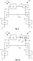
- the flow path of the exhausts leading through the expansion device and a flow path of the exhausts leading through the bypass duct may be joined near the exhaust outlet.
- This may help in mixing the exhausts from the expansion device and the bypass duct in an advantageous manner for reducing contrail production, for example, by means of a respective mixing assembly which may comprise a flow path of the exhausts exiting the expansion device and/or a flow path of the exhausts defined by the bypass duct, and/or respective outlets thereof.
- the energy conversion arrangement further comprises a water separator for separating the water from products of the fuel conversion device.
- a water separator for separating the water from products of the fuel conversion device.
- water separators can provide liquid water which has to be ejected from the aircraft anyways.
- a by-product (liquid water) of a fuel cell system can be used for contrail reduction.
- the expansion device is configured to generate electrical and/or mechanical energy by decompressing the exhausts.
- the electrical and/or mechanical energy generated by the expansion device may be used for operating the energy conversion arrangement, in particular the fuel conversion device. Consequently, an overall energetic efficiency of the energy conversion arrangement may be improved.
- the contrail reduction device is configured to introduce the droplets between the at least one throttle section and the at least one turbine section.
- the at least one injection point may be arranged after a throttle section and before a turbine section or vice versa.
- Other injection points along the flow path are possible, including injection points directly at exhaust of the aircraft.
- the energy conversion arrangement may further comprise an exhaust outlet for letting out exhausts produced in the fuel conversion system by the conversion. Introducing the droplets between the at least one throttle section and the at least one turbine section may help in optimising contrail reduction.
- the contrail reduction device is configured to introduce the droplets at at least two different introduction points into the flow path of the exhausts.
- the at least 2 different introduction points may be used independently of each other for introducing the droplets.
- the at least two introduction points allow for optimising water introduction and thus contrail reduction.
- the at least two different introduction points are spaced radially and/or axially apart from each other along the flow path. Any radial and/or axial distribution of the introduction points along the flow path can be optimised. Thereby, contrail reduction may be further improved.
- the contrail reduction device is configured to introduce the droplets into a mid-turbine section into the flow path of the exhausts.
- the mid-turbine section may be arranged between two turbine sections or within a turbine section. Introducing the droplets into a mid-turbine section can help in using thermodynamically optimised conditions for the water introduction in order to further enhance contrail reduction.
- an energy conversion arrangement for an aircraft comprising a fuel conversion device, in particular a fuel cell system, for converting at least one fuel to electrical and/or mechanical energy, and a contrail reduction device arranged in a flow path of exhausts produced in the fuel conversion device and configured to introduce droplets of water into the flow path, such that smaller droplets in the exhausts are collected through droplet coagulation.
- a fuel conversion device in particular a fuel cell system
- a contrail reduction device arranged in a flow path of exhausts produced in the fuel conversion device and configured to introduce droplets of water into the flow path, such that smaller droplets in the exhausts are collected through droplet coagulation.
- the contrail reduction device can be arranged in fluid connection with the exhaust flow and configured to introduce droplets of water into the exhaust flow.
- droplets sprayed into the flow hinder nucleation due to their own growth through condensation and the related latent heat release. This reduces the supersaturation and hence the homogeneous nucleation. Should no homogeneous nucleation occur inside of the fuel conversion system, introducing large droplets can still be beneficial.
- the droplets then provide a phase boundary for condensation in the plume. This will reduce or at least suppress homogeneous nucleation in the plume, thus also helping to reduce contrail production and enhance natural dissipation of contrails.
- the contrail reduction device further comprises a spray nozzle, a pump, and a piping, wherein the piping is in fluid connection with the pump and adapted to conduct water to the spray nozzle.
- the droplets preferably large droplets, can be introduced by one or more spray nozzles which are fed through a pump. Consequently, only a few, lightweight and low-cost additional components are needed for implementing the contrail reduction device. A power consumption of these component is relatively small. This allows for an efficient contrail reduction.
- the spray nozzle is configured to introduce droplets of water of a diameter of approx. at least 20 microns.
- droplets already present in the exhausts as they leave the fuel conversion device, in particular the fuel cell, and/or any further installation following the fuel conversion device before the exhausts reach the contrail reduction device may be expected to be relatively small, the majority of droplets having a diameter well below 1 ⁇ m (micron). Introducing droplets with the big a diameter of at least 20 ⁇ m can help in fostering droplet coagulation and thus contrail reduction.
- the water introduced by the spray nozzle is at least partly a reaction product from the fuel conversion device.
- the liquid water can be provided from a fuel cell system.
- the water from the fuel cell system is a by-product of the fuel conversion which has to be ejected from the aircraft anyway.
- the water introduced by the spray nozzle is at least partly from an external reservoir.
- the external reservoir can provide the water for the contrail reduction during load stages of the fuel conversion device where the fuel conversion device itself does not produce sufficient wastewater. Hence, providing the external reservoir helps in enhancing readiness of the contrail reduction device.
- the water introduced by the spray nozzle is at least partly from a water separation device, preferably downstream of the contrail reduction device.
- a water separation device preferably downstream of the contrail reduction device.
- water separators can provide liquid water which has to be ejected from the aircraft anyways.
- the water separation device helps in enhancing synergetic effects of the contrail reduction device.
- the energy conversion arrangement further comprises a compressing device, and an expansion device, wherein the compressing device and/or the expansion device are configured to increase the power output of the energy conversion arrangement.
- the expansion device may comprise a turbine.
- the spray nozzle is arranged in an air outlet downstream of the expansion device, preferably inside of the expansion device.
- the water vapour saturation line can be crossed and with sufficiently high supersaturation, homogeneous nucleation of water droplets may occur. This may result in a relatively large number of tiny droplets which grow through condensation. The corresponding phase change and associated latent heat release may cause a return to thermodynamic equilibrium. Therefore, introducing droplets downstream and/or even inside of the expansion device may help in fostering the production of bigger size droplets after the expansion device which then help in reducing contrail production or at least facilitate dissipation of any contrails.
- the spray nozzle comprises a plurality of nozzle elements.
- the plurality of nozzle elements may be arranged in a parallel and/or serial manner along the flow path of the exhausts to optimise the introduction of droplets. Thereby, collecting smaller droplets in the exhausts through droplet coagulation may be enhanced.
- the energy conversion arrangement further comprises an air inlet, wherein the air inlet is in fluid connection with ambient air and/or cabin air of the aircraft.
- Ambient air and/or cabin air can be fed to the energy conversion arrangement, in particular the fuel conversion device.
- ambient air can be rather dry and cold
- cabin air can rather be warm and dry in comparison to the ambient air
- fuel conversion can help in optimising conversion temperatures in the fuel conversion device and thereby contribute to the reduction of contrails.
- the energy conversion arrangement further comprises means to increase droplet coagulation, preferably a vortex generator.
- a vortex generator Within a vortex of the exhausts generated by the vortex generator, local pressure variations and/or alternations of laminar and/or turbulent flows of the exhausts may help in fostering droplet coagulation.
- the vortex generator can further reduce contrails.
- the energy conversion arrangement further comprises sensors to measure ambient conditions and/or a sensor to measure condensation and droplet sizes.
- Ambient conditions, condensation and/or droplet sizes can significantly influence contrail formation.
- measuring ambient conditions, condensation and/or droplet sizes by respective sensors can help in optimising operation of the energy conversion arrangement, in particular the contrail reduction device, and thus contribute to effective contrail reduction.
- the energy conversion arrangement further comprises heating and/or cooling devices to adapt a temperature of the water in order to increase the droplet size.
- Increasing the droplet size can help in fostering coagulation.
- operation of the energy conversion arrangement, in particular the contrail reduction device can be further optimised for effective contrail reduction.
- the energy conversion arrangement further comprises at least one of a humidifier, a dehumidifier and a heat exchanger.
- the humidifier, dehumidifier and/ or heat exchanger may help in further influence droplet coagulation.
- the humidifier, dehumidifier and/ or heat exchanger can help in optimising operation of the energy conversion arrangement, in particular the contrail reduction device, and thus contribute to effective contrail reduction.
- an energy conversion arrangement for an aircraft comprising a fuel conversion device, in particular a fuel cell system, for converting at least one fuel to electrical and/or mechanical energy, and an exhaust outlet for letting out exhausts produced in the fuel conversion device by the fuel conversion; wherein at least one heating device is arranged in a flow path of the exhausts before the exhaust outlet and is configured to heat up the exhausts.
- the heating device provides a heat source between the fuel conversion device and the exhaust outlet of the aircraft.
- the heating reduces the saturation, i.e., relative humidity, of the exhaust gas flow.
- a lower saturation reduces or altogether prevents droplet formation and condensation in the exhaust system. Droplet formation might still occur in the plume of the propulsion system. However, a likelihood of the formation of a large number of small droplets is reduced. This decreases the risk of contrail formation.
- the solution is lighter, has lower costs and uses less space and power.
- the energy conversion arrangement may further comprise an expansion device arranged in the flow path of the exhausts and configured to generate electrical and/or mechanical energy by expanding the exhausts.
- the electrical and/or mechanical energy generated by the expansion device may be used for operating the energy conversion arrangement, in particular the fuel conversion device. Consequently, an overall energetic efficiency of the energy conversion arrangement may be improved.
- the expansion device comprises at least one turbine.
- the at least one turbine By means of the at least one turbine, electrical and/or mechanical energy may be generated by the decompression of the exhausts.
- the at least one turbine helps in improving an overall energetic efficiency of the energy conversion arrangement.
- the expansion device is arranged in the flow path of the exhausts after the heating device.
- the expansion device may be arranged between the heating device and the air outlet, i.e., before the air outlet.
- the heating device may thereby raise a temperature of the exhausts and may thereby increase a power output of the expansion device if used for generating electrical and/or mechanical energy.
- the heating device helps in improving an overall energetic efficiency of the energy conversion arrangement.
- the heating device comprises a catalytic converter for converting fuel residuals which have been left unconverted by the fuel conversion device to heat.
- the catalytic converter maybe configured to convert at least one fuel to heat.
- the catalytic converter e.g., provided as a catalytic burner, can process leftover hydrogen from a fuel cell reaction. The hydrogen reacts with oxygen to water while releasing heat. Thereby, the catalytic burner may help in enhancing contrail reduction by means of the heating device. Furthermore, the catalytic can prevent fuel emissions from the energy conversion arrangement.
- the catalytic converter is configured to convert an additional fuel to heat. Also, additional hydrogen might be added to the flow upstream of the catalytic converter. Thereby, the effect of the catalytic converter for providing heat to be added to the exhausts through the heating device can be optimised for further enhanced contrail reduction.
- the energy conversion arrangement further comprises a residual sensor element configured to measure at least one residual parameter value corresponding to an amount of the fuel residuals.
- the residual sensor element may measure an amount of fuel residuals, e.g., hydrogen residuals, in the exhausts.
- the amount of fuel residuals can be expressed by means of the residual parameter value.
- the residual parameter value can be used for optimising operation of the energy conversion arrangement in order to further reduce contrail production.
- the energy conversion arrangement further comprises an auxiliary fuel inlet arranged in the flow path of the exhausts before the catalytic converter for adding at least one fuel to the exhausts.
- an auxiliary fuel inlet arranged in the flow path of the exhausts before the catalytic converter for adding at least one fuel to the exhausts.
- the heating device comprises at least one combustion unit configured to burn at least one fuel for heating up the exhausts.
- the combustion can be supplied with hydrogen from the same source as for the fuel cell.
- the combustion unit can provide additional heat to be introduced by the heating device. Thereby, the combustion unit can help in assuring a desired degree of contrail reduction.
- the heating device comprises at least one heat exchange unit configured to heat up the exhausts.
- the heat exchanger can transfer heat from hotter flows in the fuel cell system.
- the heat exchange unit may provide any kind of waste and/or surplus heat to be used by the heating device. Thereby, the heat exchange unit can provide an efficient way for contrail reduction.
- the energy conversion arrangement further comprises a compressing device for supplying the fuel conversion device with compressed supply air to be used for the fuel conversion; wherein the at least one heat exchange unit is configured to extract heat from the compressing device and/or the compressed supply air to be used for the conversion.
- Compressed supply air may be cooled by means of the heat exchange unit.
- the heating device may help in further improving an overall energetic efficiency of the energy conversion arrangement, while at the same time contributing to contrail reduction.
- the at least one heat exchange unit is configured to extract heat from the fuel conversion device and/or any auxiliary energy conversion unit.
- the heat exchange unit may be configured to cool down at least parts of the heat exchange unit and/or any auxiliary energy conversion unit.
- auxiliary energy conversion units may be electrical and/or mechanical energy converters.
- the heating device may help in further improving an overall energetic efficiency of the energy conversion arrangement, while at the same time contributing to contrail reduction.
- the at least one heating device comprises an electrically powered heating element.
- the electric power for the electric heating can be supplied from the energy conversion arrangement.
- the electric power may be provided through any energy recuperation means. Heating the exhausts by means of electric power may help in assuring a desired degree of contrail reduction.
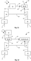
- an energy conversion arrangement for an aircraft comprising a fuel conversion device, in particular a fuel cell system, for converting at least one fuel to electrical and/or mechanical energy, and an exhaust outlet for letting out exhausts produced in the fuel conversion device by the fuel conversion; wherein at least one mixing assembly is arranged in a flow path of the exhausts before and/or after the exhaust outlet and is configured to mix the exhausts with further exhausts from the energy conversion arrangement.
- Waste heat of a fuel cell aircraft system can be used in the mixing assembly to avoid a high supersaturation in the plume of the discharged humid exhaust flow of fuel conversion device, e.g., a fuel cell system.
- This can be achieved by mixing the humid exhaust flow of the air supply system with a warm and dry gas flow before it can mix with the cold ambient air.
- a decreased number of droplets reduces an amount of possible ice crystal formation and hence reduces contrail impact.
- a corresponding solution may utilise any heat source for providing the further exhausts.
- the energy conversion arrangement further comprises a thermal management system configured to produce the further exhausts.
- a further exhaust flow provided by the thermal management system can be advantageous as it offers large amounts of waste heat and is usually located in close vicinity to the humid exhaust flow of the fuel conversion device. Consequently, the thermal management system may contribute to enhancing and overall energetic efficiency of the energy conversion arrangement, while at the same time reducing contrail production.
- the thermal management system is configured as a heat exchanger.
- the thermal management system may draw waste and/or surplus heat from any component of the aircraft in order to provide the further exhausts. This helps in further improving an overall energetic efficiency of the aircraft while at the same time contributing to contrail reduction.
- the thermal management system comprises at least one heat exchanger element configured to extract heat from the fuel conversion device and/or any auxiliary energy conversion unit.
- the heat exchanger element can help in cooling the fuel conversion device and/or any auxiliary energy conversion unit down to a desired respective operating temperature. This additionally helps in further improving an overall energetic efficiency of the aircraft while at the same time contributing to contrail reduction.
- the thermal management system is configured to take in cooling air, heat up the cooling air, and discharge the heated-up cooling air as the further exhausts. Otherwise, the cooling air would probably have to be injected from the aircraft anyway. Consequently, using the cooling air for at least partly providing the further exhausts provides synergetic effects when applying the further exhausts for contrail reduction.
- the thermal management system is configured to take in the cooling air from ambient surroundings. If taken up from ambient surroundings, in particular at cruising altitudes of aircrafts, the cooling air may be particularly cold and dry. Hence, heating up the cooling air by means of the thermal management system even further adds to the relative dryness of the cooling air. Thus, mixing the relatively dry cooling air with the exhausts can help in reducing humidity of the overall exhausts of the aircraft, which may be beneficial for reducing contrails.
- the thermal management system is configured to provide the fuel conversion device with a coolant at a coolant inlet temperature, and to receive back from the fuel conversion device the coolant at a coolant outlet temperature, wherein the coolant inlet temperature is lower than the coolant outlet temperature at least when the fuel conversion device operates at an operating temperature.
- the coolant thus helps in regulating the temperature of the fuel conversion device. Consequently, the coolant may contribute to enhancing and overall energetic efficiency of the energy conversion arrangement, while at the same time reducing contrail production.
- the energy conversion arrangement further comprises an air supply system for supplying the fuel conversion device with supply air for the fuel conversion arranged upstream of the exhaust outlet. Consequently, the exhausts may at least partly flow through the air supply system. Consequently, the air supply system may be used to heat up the exhausts. This may help in reducing contrail production in that a relative humidity of the exhausts is being reduced.
- the air supply system comprises a compressing device for supplying the fuel conversion device with compressed inlet air to be used for the fuel conversion; and at least one heat exchange unit configured to extract heat from the compressing device and/or the compressed air to be used for the conversion.
- the compressing device and/or compressed air may be cooled by means of the heat exchange unit.
- the heat exchange may help to improve overall energetic efficiency of the energy conversion arrangement, while at the same time contributing to contrail reduction.
- the at least one heat exchange unit configured to heat up the exhausts. Heating up the exhausts may help in reducing a relative humidity of the exhausts. The reduced relative humidity may decrease the amount of contrails produced and may facilitate dissipation of any remaining contrails.
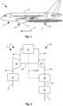
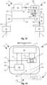
- Fig. 2 shows a schematic illustration of an energy conversion arrangement 10 of the energy system 2 of the aircraft 1.
- the energy conversion arrangement 10 comprises a fuel conversion device 11, for example, provided as a fuel cell system for converting hydrogen to electricity and predominantly water vapour as exhausts E of the fuel conversion.
- Air A for example taken from ambient surroundings, such as the atmosphere 7, and/or from inside the hull 4, e.g., from a cabin of the aircraft 1, is provided to the fuel conversion arrangement 11 through an air inlet 12 of the energy conversion arrangement 10.
- the exhausts E are released to the atmosphere 7 through an exhaust outlet 13 of the energy conversion arrangement 10.
Landscapes
- Engineering & Computer Science (AREA)
- Chemical & Material Sciences (AREA)
- Aviation & Aerospace Engineering (AREA)
- Sustainable Development (AREA)
- Sustainable Energy (AREA)
- Life Sciences & Earth Sciences (AREA)
- Chemical Kinetics & Catalysis (AREA)
- Electrochemistry (AREA)
- General Chemical & Material Sciences (AREA)
- Manufacturing & Machinery (AREA)
- Combustion & Propulsion (AREA)
- Mechanical Engineering (AREA)
- Fuel Cell (AREA)
Priority Applications (16)
| Application Number | Priority Date | Filing Date | Title |
|---|---|---|---|
| EP23290051.4A EP4574671A1 (de) | 2023-12-21 | 2023-12-21 | Energieumwandlungsanordnung, energiesystem und flugzeug damit |
| DE102024122543.2A DE102024122543A1 (de) | 2023-12-21 | 2024-08-07 | Energieumwandlungsanordnung, energiesystem und flugzeug mit einer solchen anordnung |
| DE102024122544.0A DE102024122544A1 (de) | 2023-12-21 | 2024-08-07 | Energieumwandlungsanordnung, energiesystem und flugzeug damit |
| DE102024122542.4A DE102024122542A1 (de) | 2023-12-21 | 2024-08-07 | Energieumwandlungsanordnung, energiesystem und flugzeug mit einer solchen anordnung |
| EP24290029.8A EP4574668A1 (de) | 2023-12-21 | 2024-08-07 | Verfahren, steuerprogramm, computerlesbarer datenträger und steuereinrichtung zum steuern einer energieumwandlungsanordnung sowie flugzeug damit |
| EP24290026.4A EP4574666A1 (de) | 2023-12-21 | 2024-08-07 | Verfahren, steuerprogramm, computerlesbarer datenträger und steuereinrichtung zum steuern einer energieumwandlungsanordnung sowie flugzeug damit |
| EP24290027.2A EP4574667A1 (de) | 2023-12-21 | 2024-08-07 | Verfahren, steuerprogramm, computerlesbarer datenträger und steuereinrichtung zum steuern einer energieumwandlungsanordnung sowie flugzeug damit |
| DE102024122546.7A DE102024122546A1 (de) | 2023-12-21 | 2024-08-07 | Energieumwandlungsanordnung, energiesystem und flugzeug damit |
| DE102024122550.5A DE102024122550A1 (de) | 2023-12-21 | 2024-08-07 | Energieumsetzungsanordnung, energiesystem undl uftfahrzeug, das diese umfasst |
| EP24290028.0A EP4574673A1 (de) | 2023-12-21 | 2024-08-07 | Energieumwandlungsanordnung, energiesystem und flugzeug damit |
| EP24214238.8A EP4574661A1 (de) | 2023-12-21 | 2024-11-20 | Energieumwandlungsanordnung, energiesystem und flugzeug damit |
| EP24214240.4A EP4574662A1 (de) | 2023-12-21 | 2024-11-20 | Energieumwandlungsanordnung, energiesystem und flugzeug damit |
| EP24216787.2A EP4574663A1 (de) | 2023-12-21 | 2024-12-02 | Energieumwandlungsanordnung, energiesystem und flugzeug damit |
| EP24221585.3A EP4574665A1 (de) | 2023-12-21 | 2024-12-19 | Energieumwandlungsanordnung, energiesystem, antriebseinheit und flugzeug damit |
| US18/987,902 US20250207538A1 (en) | 2023-12-21 | 2024-12-19 | Energy conversion arrangement, energy system and aircraft comprising same |
| EP24221581.2A EP4574664A1 (de) | 2023-12-21 | 2024-12-19 | Energieumwandlungsanordnung, energiesystem und flugzeug damit |
Applications Claiming Priority (1)
| Application Number | Priority Date | Filing Date | Title |
|---|---|---|---|
| EP23290051.4A EP4574671A1 (de) | 2023-12-21 | 2023-12-21 | Energieumwandlungsanordnung, energiesystem und flugzeug damit |
Publications (1)
| Publication Number | Publication Date |
|---|---|
| EP4574671A1 true EP4574671A1 (de) | 2025-06-25 |
Family
ID=89619427
Family Applications (1)
| Application Number | Title | Priority Date | Filing Date |
|---|---|---|---|
| EP23290051.4A Pending EP4574671A1 (de) | 2023-12-21 | 2023-12-21 | Energieumwandlungsanordnung, energiesystem und flugzeug damit |
Country Status (1)
| Country | Link |
|---|---|
| EP (1) | EP4574671A1 (de) |
Citations (11)
| Publication number | Priority date | Publication date | Assignee | Title |
|---|---|---|---|---|
| US5005355A (en) | 1988-08-24 | 1991-04-09 | Scipar, Inc. | Method of suppressing formation of contrails and solution therefor |
| EP2150692A2 (de) | 2007-05-26 | 2010-02-10 | Rolls-Royce plc | Verfahren und vorrichtung zur unterdrückung von flugzeugtriebwerkkondensstreifen |
| EP2153043A2 (de) | 2007-05-26 | 2010-02-17 | Rolls-Royce plc | Verfahren und vorrichtung zur unterdrückung von flugtriebwerk-kondensstreifen |
| US7971438B2 (en) | 2006-05-05 | 2011-07-05 | Rolls-Royce Plc | Gas turbine engine having a heat exchanger arrangement for exhaust gas flows |
| US20150260097A1 (en) * | 2012-10-31 | 2015-09-17 | Mitsubishi Hitachi Power System, Ltd. | Power generation system and operation method of power generation system |
| US20170077534A1 (en) * | 2015-09-13 | 2017-03-16 | Honeywell International Inc. | Fuel cell regulation using loss recovery systems |
| EP3961012A1 (de) | 2020-09-01 | 2022-03-02 | Airbus Operations, S.L.U. | Vorrichtung und verfahren zur beurteilung von flugzeugflugkondensstreifen |
| WO2022242865A1 (en) * | 2021-05-20 | 2022-11-24 | Volvo Truck Corporation | A fuel cell system, a method of controlling a fuel cell system, and a vehicle comprising a fuel cell system |
| US11565607B2 (en) * | 2020-06-15 | 2023-01-31 | Joby Aero, Inc. | High efficiency hydrogen fueled high altitude thermodynamic fuel cell system and aircraft using same |
| US11579050B2 (en) | 2020-03-11 | 2023-02-14 | Airbus Sas | System for sampling and analyzing contrails generated by an aircraft |
| WO2023239965A2 (en) * | 2022-06-10 | 2023-12-14 | Zeroavia Ltd | Turbo-evaporative cooled ht-pem fuel-cell system |
-
2023
- 2023-12-21 EP EP23290051.4A patent/EP4574671A1/de active Pending
Patent Citations (11)
| Publication number | Priority date | Publication date | Assignee | Title |
|---|---|---|---|---|
| US5005355A (en) | 1988-08-24 | 1991-04-09 | Scipar, Inc. | Method of suppressing formation of contrails and solution therefor |
| US7971438B2 (en) | 2006-05-05 | 2011-07-05 | Rolls-Royce Plc | Gas turbine engine having a heat exchanger arrangement for exhaust gas flows |
| EP2150692A2 (de) | 2007-05-26 | 2010-02-10 | Rolls-Royce plc | Verfahren und vorrichtung zur unterdrückung von flugzeugtriebwerkkondensstreifen |
| EP2153043A2 (de) | 2007-05-26 | 2010-02-17 | Rolls-Royce plc | Verfahren und vorrichtung zur unterdrückung von flugtriebwerk-kondensstreifen |
| US20150260097A1 (en) * | 2012-10-31 | 2015-09-17 | Mitsubishi Hitachi Power System, Ltd. | Power generation system and operation method of power generation system |
| US20170077534A1 (en) * | 2015-09-13 | 2017-03-16 | Honeywell International Inc. | Fuel cell regulation using loss recovery systems |
| US11579050B2 (en) | 2020-03-11 | 2023-02-14 | Airbus Sas | System for sampling and analyzing contrails generated by an aircraft |
| US11565607B2 (en) * | 2020-06-15 | 2023-01-31 | Joby Aero, Inc. | High efficiency hydrogen fueled high altitude thermodynamic fuel cell system and aircraft using same |
| EP3961012A1 (de) | 2020-09-01 | 2022-03-02 | Airbus Operations, S.L.U. | Vorrichtung und verfahren zur beurteilung von flugzeugflugkondensstreifen |
| WO2022242865A1 (en) * | 2021-05-20 | 2022-11-24 | Volvo Truck Corporation | A fuel cell system, a method of controlling a fuel cell system, and a vehicle comprising a fuel cell system |
| WO2023239965A2 (en) * | 2022-06-10 | 2023-12-14 | Zeroavia Ltd | Turbo-evaporative cooled ht-pem fuel-cell system |
Non-Patent Citations (2)
| Title |
|---|
| H. CRUZ CHAMPIONS. KABELAC: "Multifunctional fuel cell system for civil aircraft: Study of the cathode exhaust gas dehumidification", INTERNATIONAL JOURNAL OF HYDROGEN ENERGY, vol. 42, 2017, pages 29518 - 29531, XP085249062, Retrieved from the Internet <URL:https://doi.rg/10.1016/j.ijhydene.2017.09.175> DOI: 10.1016/j.ijhydene.2017.09.175 |
| TEYMOURTASH ET AL.: "The effects, of rate of expansion and injection of water droplets on the entropy generation of nucleating steam flow in a Laval nozzle", HEAT MASS TRANSFER, vol. 45, no. 1185-1198, 2009, pages 1196 |
Similar Documents
| Publication | Publication Date | Title |
|---|---|---|
| CA2502951C (en) | Device for producing water on board of an airplane | |
| US8137169B2 (en) | Arrangement and method for utilizing the heat of waste air for heating the bilge area of aircraft | |
| RU2673123C2 (ru) | Способ и устройство для снабжения инертным газом топливного бака | |
| JP4300682B2 (ja) | 走行体 | |
| US20260008551A1 (en) | Aircraft propulsion system and method | |
| EP4509398A1 (de) | Wärmeverwaltungssystem für ein brennstoffzellenflugzeug | |
| EP4574660A1 (de) | Energieumwandlungsanordnung, energiesystem und flugzeug damit | |
| EP4509409A1 (de) | Integration eines gondelluftwärmetauschers für ein mit wasserstoffbetriebener brennstoffzelle angetriebenes flugzeug | |
| US12497188B2 (en) | Liquid hydrogen feed system for fuel cell powered aircraft | |
| EP4574671A1 (de) | Energieumwandlungsanordnung, energiesystem und flugzeug damit | |
| EP4574678A1 (de) | Energieumwandlungsanordnung und flugzeug damit | |
| EP4574670A1 (de) | Energieumwandlungsanordnung, energiesystem und flugzeug damit | |
| EP4574672A1 (de) | Energieumwandlungsanordnung, energiesystem und flugzeug damit | |
| US20250207538A1 (en) | Energy conversion arrangement, energy system and aircraft comprising same | |
| US20250206153A1 (en) | Energy conversion arrangement, energy system and aircraft comprising same | |
| US20250206154A1 (en) | Energy conversion arrangement, energy system and aircraft comprising same | |
| EP4574662A1 (de) | Energieumwandlungsanordnung, energiesystem und flugzeug damit | |
| EP4574673A1 (de) | Energieumwandlungsanordnung, energiesystem und flugzeug damit | |
| EP4510250A2 (de) | Niedertemperatur-protonenaustauschmembran-ladeluftwärmetauscher | |
| EP4574661A1 (de) | Energieumwandlungsanordnung, energiesystem und flugzeug damit | |
| EP4691913A1 (de) | Energieumwandlungsanordnung, energiesystem und flugzeug damit | |
| EP4574664A1 (de) | Energieumwandlungsanordnung, energiesystem und flugzeug damit | |
| EP4509408A2 (de) | Konfiguration für ein lh2-brennstoffzellenflugzeug mit verteilten systemen | |
| EP4509410A1 (de) | Gepumpte zweiphasenkühlung von flugzeugelektronik | |
| EP4510251A2 (de) | Start eines hochtemperatur-protonenaustauschmembran (htpem)-brennstoffzellenflugzeugs mit mehreren stromerzeugungseinheiten |
Legal Events
| Date | Code | Title | Description |
|---|---|---|---|
| PUAI | Public reference made under article 153(3) epc to a published international application that has entered the european phase |
Free format text: ORIGINAL CODE: 0009012 |
|
| STAA | Information on the status of an ep patent application or granted ep patent |
Free format text: STATUS: THE APPLICATION HAS BEEN PUBLISHED |
|
| AK | Designated contracting states |
Kind code of ref document: A1 Designated state(s): AL AT BE BG CH CY CZ DE DK EE ES FI FR GB GR HR HU IE IS IT LI LT LU LV MC ME MK MT NL NO PL PT RO RS SE SI SK SM TR |
|
| STAA | Information on the status of an ep patent application or granted ep patent |
Free format text: STATUS: REQUEST FOR EXAMINATION WAS MADE |
|
| 17P | Request for examination filed |
Effective date: 20251218 |