EP4574665A1 - Energieumwandlungsanordnung, energiesystem, antriebseinheit und flugzeug damit - Google Patents
Energieumwandlungsanordnung, energiesystem, antriebseinheit und flugzeug damit Download PDFInfo
- Publication number
- EP4574665A1 EP4574665A1 EP24221585.3A EP24221585A EP4574665A1 EP 4574665 A1 EP4574665 A1 EP 4574665A1 EP 24221585 A EP24221585 A EP 24221585A EP 4574665 A1 EP4574665 A1 EP 4574665A1
- Authority
- EP
- European Patent Office
- Prior art keywords
- exhausts
- energy conversion
- conversion arrangement
- contrail
- fuel
- Prior art date
- Legal status (The legal status is an assumption and is not a legal conclusion. Google has not performed a legal analysis and makes no representation as to the accuracy of the status listed.)
- Pending
Links
Images


Classifications
-
- B—PERFORMING OPERATIONS; TRANSPORTING
- B64—AIRCRAFT; AVIATION; COSMONAUTICS
- B64D—EQUIPMENT FOR FITTING IN OR TO AIRCRAFT; FLIGHT SUITS; PARACHUTES; ARRANGEMENT OR MOUNTING OF POWER PLANTS OR PROPULSION TRANSMISSIONS IN AIRCRAFT
- B64D27/00—Arrangement or mounting of power plants in aircraft; Aircraft characterised by the type or position of power plants
- B64D27/02—Aircraft characterised by the type or position of power plants
- B64D27/30—Aircraft characterised by electric power plants
- B64D27/35—Arrangements for on-board electric energy production, distribution, recovery or storage
- B64D27/355—Arrangements for on-board electric energy production, distribution, recovery or storage using fuel cells
-
- B—PERFORMING OPERATIONS; TRANSPORTING
- B64—AIRCRAFT; AVIATION; COSMONAUTICS
- B64D—EQUIPMENT FOR FITTING IN OR TO AIRCRAFT; FLIGHT SUITS; PARACHUTES; ARRANGEMENT OR MOUNTING OF POWER PLANTS OR PROPULSION TRANSMISSIONS IN AIRCRAFT
- B64D33/00—Arrangement in aircraft of power plant parts or auxiliaries not otherwise provided for
- B64D33/04—Arrangement in aircraft of power plant parts or auxiliaries not otherwise provided for of exhaust outlets or jet pipes
-
- B—PERFORMING OPERATIONS; TRANSPORTING
- B64—AIRCRAFT; AVIATION; COSMONAUTICS
- B64D—EQUIPMENT FOR FITTING IN OR TO AIRCRAFT; FLIGHT SUITS; PARACHUTES; ARRANGEMENT OR MOUNTING OF POWER PLANTS OR PROPULSION TRANSMISSIONS IN AIRCRAFT
- B64D37/00—Arrangements in connection with fuel supply for power plant
- B64D37/30—Fuel systems for specific fuels
-
- H—ELECTRICITY
- H01—ELECTRIC ELEMENTS
- H01M—PROCESSES OR MEANS, e.g. BATTERIES, FOR THE DIRECT CONVERSION OF CHEMICAL ENERGY INTO ELECTRICAL ENERGY
- H01M8/00—Fuel cells; Manufacture thereof
- H01M8/04—Auxiliary arrangements, e.g. for control of pressure or for circulation of fluids
- H01M8/04082—Arrangements for control of reactant parameters, e.g. pressure or concentration
- H01M8/04089—Arrangements for control of reactant parameters, e.g. pressure or concentration of gaseous reactants
- H01M8/04119—Arrangements for control of reactant parameters, e.g. pressure or concentration of gaseous reactants with simultaneous supply or evacuation of electrolyte; Humidifying or dehumidifying
- H01M8/04126—Humidifying
- H01M8/04141—Humidifying by water containing exhaust gases
-
- H—ELECTRICITY
- H01—ELECTRIC ELEMENTS
- H01M—PROCESSES OR MEANS, e.g. BATTERIES, FOR THE DIRECT CONVERSION OF CHEMICAL ENERGY INTO ELECTRICAL ENERGY
- H01M8/00—Fuel cells; Manufacture thereof
- H01M8/04—Auxiliary arrangements, e.g. for control of pressure or for circulation of fluids
- H01M8/04082—Arrangements for control of reactant parameters, e.g. pressure or concentration
- H01M8/04089—Arrangements for control of reactant parameters, e.g. pressure or concentration of gaseous reactants
- H01M8/04119—Arrangements for control of reactant parameters, e.g. pressure or concentration of gaseous reactants with simultaneous supply or evacuation of electrolyte; Humidifying or dehumidifying
- H01M8/04156—Arrangements for control of reactant parameters, e.g. pressure or concentration of gaseous reactants with simultaneous supply or evacuation of electrolyte; Humidifying or dehumidifying with product water removal
- H01M8/04164—Arrangements for control of reactant parameters, e.g. pressure or concentration of gaseous reactants with simultaneous supply or evacuation of electrolyte; Humidifying or dehumidifying with product water removal by condensers, gas-liquid separators or filters
-
- H—ELECTRICITY
- H01—ELECTRIC ELEMENTS
- H01M—PROCESSES OR MEANS, e.g. BATTERIES, FOR THE DIRECT CONVERSION OF CHEMICAL ENERGY INTO ELECTRICAL ENERGY
- H01M2250/00—Fuel cells for particular applications; Specific features of fuel cell system
- H01M2250/20—Fuel cells in motive systems, e.g. vehicle, ship, plane
Definitions
- the present disclosure relates to the field of anthropogenic climate change due to cloudiness caused by contrails produced by energy systems of aircrafts.
- the disclosure relates to an energy conversion arrangement for an aircraft, an energy system, in particular for powering a propulsion unit for propelling an aircraft, to a propulsion unit, and to an aircraft comprising an energy conversion arrangement, an energy system and/or a propulsion unit.
- hydrogen powered fuel cell aircraft are an interesting alternative to conventional aircraft propulsion and also for power generation, in that they may replace conventional auxiliary power units (APUs).
- APUs auxiliary power units
- Fuel cells emit no soot particles. Due to the low concentration of ambient aerosols, only a few droplets can form through heterogeneous nucleation. Instead, most droplets form through homogeneous nucleation during which molecules condensate and form nuclei without the presence of foreign ions or particles. Homogeneous nucleation can occur inside the fuel cell system, e.g., in a turbine or a nozzle, or in the plume during mixing and cooling with ambient air. The occurrence and place of homogeneous nucleation depends on the system architecture, operating conditions and ambient conditions. Homogeneous nucleation leads to a high concentration of small droplet radii, often below one micron. If the droplets freeze to persistent ice crystals, the resulting contrail might have a stronger climate impact than a contrail of a conventional aircraft engine. Therefore, it is important to reduce the contrail formation of fuel cell aircraft as much as possible or avoid it altogether.
- EP 3 961 012 A1 relates to an aircraft flight contrail assessment device comprising a contrail sensor adapted to produce contrails data representative of an atmosphere parameter having an influence on the formation of contrails or an observation parameter varying depending on at least the presence of one or more contrails, and a processing unit adapted to calculate at least a contrails value representative of an amount of contrail, based on said contrails data.
- the invention provides such device as well a corresponding method to evaluate the amount of contrails produced by an aircraft during a flight.
- US 11 579 050 B2 relates to a system, configured for being on board an aircraft.
- the system includes a probe for collecting samples of contrail, a chamber for collecting the samples, a collecting conduit for conducting the samples from the collecting probe the collecting chamber and at least one device for measuring at least one parameter characterizing the samples in the collecting conduit while they are conducted from the collecting probe to the collecting chamber.
- an energy conversion arrangement for an aircraft comprising at least one exhaust outlet for letting out exhausts produced by a fuel conversion device, in particular a fuel cell system, for converting at least one fuel to electrical and/or mechanical energy in the fuel conversion device; and at least one exhaust assembly configured to admix a stream of the exhausts from the at least one exhaust outlet with ambient air from the ambient surroundings in at least one mixing zone to promote a growth of water droplets through at least partly condensing water vapor contained in the exhausts in the mixing zone.
- an energy system in particular for powering a propulsion unit for propelling an aircraft, comprising a corresponding energy conversion arrangement.
- the energy system may comprise the propulsion unit.
- the energy system may be provided as an engine and/or power plant for an aircraft.
- a propulsion unit for propelling an aircraft comprising a corresponding energy conversion arrangement and/or a corresponding energy system.
- an aircraft comprising a corresponding energy conversion arrangement, a corresponding energy system, and/or a corresponding propulsion unit.
- the at least one exhaust assembly can be arranged at the at least one exhaust outlet.
- the exhausts from the exhaust outlet can be directly led into or along the exhaust assembly. This helps in providing a simple, yet reliable and efficient way to establish the mixing zone for contrail reduction right at the exhaust outlet without the need for further major system components which in turn would lead to increased weight and complexity.
- the at least one exhaust outlet can be configured as a part of the at least one exhaust assembly.
- the at least one exhaust assembly can be a part of the exhaust outlet.
- the energy conversion arrangement, in particular the exhaust assembly can be designed to provide the mixing zone in a compact and lightweight manner.
- the mixing zone enables to increase a dwell time of exhausts at the first contact point between the internal warm, moist exhaust flow and the cold and dry ambient air.
- This contact point is of high relevance for droplet formation, as the flow with high content of water suffers a sudden decrease in its temperature triggering homogeneous nucleation and, thus, creating a large number of droplets.
- the droplets formed in this area are numerous and do not grow very large compared to the ones formed further downstream, due to the fact that the condensed water is distributed over an increased number of droplets.
- the proposed solution provides a reduction of contrail formation for all kinds of aircraft, including but not limited to fuel cell aircraft.
- the proposed solution is lighter, cheaper, uses less space and power and creates no new emissions.
- the proposed solution allows for mitigating a possible disadvantage of fuel cell powered aircrafts by reducing their contribution to contrail production, and thus enhancing their environmental friendliness.
- the mixing zone is configured to gradually admix the exhausts to the ambient air. Gradually admixing the exhausts to the ambient air enables to increase the dwell time of any droplets in the mixing zone, and thus promotes droplet growth. This further helps in avoiding or at least limiting contrail formation as well as unwanted contrail impacts
- the mixing zone comprises a pre-mixing zone and a main mixing zone, wherein at least one exhaust tapping passage of the exhaust assembly leads a branched-off flow of exhausts to a pre-mixing zone and a main passage of the exhaust arrangement leads a main flow of exhausts to the main mixing zone.
- a small portion of the warm, moist flow of exhaust can be mixed with the cold and dry ambient air. This leads to the formation of initially relatively small droplets after the pre-mixing zone. These droplets can then be transported into the main mixing zone where a relatively large remaining portion of the warm, moist flow of exhausts mixes with the cold and dry ambient air. There, the earlier formed relatively small droplets can provide a phase boundary on which condensation will take place.
- the condensation and associated release of latent heat can reduce a subcooling of the water vapor contained in the exhausts. Hence, a nucleation rate of new droplets in the main mixing zone is much smaller than without the pre-mixing zone. Overall, the resulting droplet spectrum consists of fewer, larger droplets. This can help to further reduce unwanted contrail impacts.
- the tapping passage is formed as a side channel within a wall portion of the exhaust assembly at least sectionwise separating the exhausts from the ambient air and/or between a sleeve and an inner wall section of the main passage.
- the exhaust assembly is configured to promote formation of an exhaust vortex of exhausts recirculating in the mixing zone. Creating a recirculation region allows a number of recently created droplets to increase their residence time due to the immersion in the recirculation zone, hence resulting in further time in supersaturated flow where droplet growth happens. This results in a reduced number of small droplets compared to the non-recirculation case, which is beneficial for avoiding contrail formation or at least for the reduction of unwanted contrail impacts.
- the exhaust assembly is configured to promote formation of an air vortex of ambient air recirculating in the mixing zone.
- a deliberate flow stall may be promoted in the mixing zone.
- the ambient air may thereby be sucked into the mixing zone and recirculate in the vortex. This further helps in reducing the number of small droplets compared to the non-recirculation case, which is beneficial for avoiding contrail formation or at least for the reduction of unwanted contrail impacts.
- the exhaust vortex and air vortex contact each other in a recirculation region of the mixing zone.
- the recirculation region may be defined by the extension of the parts of the exhaust vortex and the air vortex recirculating.
- the dwell time of droplets in the mixing zone may be increased by this recirculation for gradual temperature and relative moisture adjustment between the exhausts on the one hand, and the ambient air on the other hand. This additionally helps in reducing the number of small droplets compared to the non-recirculation case, which is beneficial for avoiding control formation or at least for the reduction of unwanted contrail impacts.
- the exhaust assembly comprises a lip providing at least one trailing edge configured to create the mixing zone.
- the trailing edge can be formed at and/or provided by the lip.
- the lip and thus the at least one trailing edge can be configured such that formation of the mixing zone, in particular of the recirculation region, is enhanced.
- the lip thereby helps in reducing the number of small droplets compared to the non-recirculation case, which is beneficial for avoiding control formation or at least for the reduction of unwanted contrail impacts.
- a ratio of a lip height of the lip to an outlet height of the exhaust outlet exceeds a value of 0.05, preferably 0.06, most preferably 0.07.
- a minimal lip height of the lip can amount to approx. 5 mm.
- An outlet height of the exhaust outlet may amount to between 50 to 90 mm, preferably 60 to 80 mm, most preferably to around 70 mm.
- the spoiler element can least sectionwise be formed as a spoiler flap, guiding surface and/or guide vane which can be moved and/or deflected between the stowed position and the deployed position.
- the spoiler element In at least one position, preferably the deployed position, the spoiler element can be inclined under an acute angle with respect to an outer wall and/or a channel wall for guiding the ambient air and/or the exhausts towards the mixing assembly, respectively. This further helps in finding a balance between potential drag introduced by the lip on the one hand, and the advantages of contrail avoidance or at least reduction of unwanted contrail impacts on the other hand, for example, in that the spoiler element may only be deployed in case of a potential contrail formation.
- a vertical height of the mixing zone can depend on the height of the lip and/or the spoiler device.
- the height of the mixing zone may be defined by a lip height and/or spoiler height.
- a ratio of a lip height to the mixing height may amount to or less than 2.
- the mixing height may amount to 3 to 7 mm, preferably 4 to 6 mm, most preferably around 5 mm.
- the exhaust assembly comprises a concave lip section providing a cavity at least partly providing the mixing zone. Due to the cavity, two relatively sharp trailing edges can be provided for the exhausts and the ambient air, respectively. These relatively sharp trailing edges may help to create respective flow stalls.
- the cavity may help to further promote formation of the mixing zone, in particular formation of the recirculation region. Thereby, the lip height and thus, weight and drag of the exhaust assembly may be reduced.
- an outlet passage leading to the exhaust outlet is configured to provide an outflow direction extending essentially in parallel or at least under an acute angle with respect to a flow direction of ambient air.
- the outlet passage can be configured to prevent that flows of the ambient air and the exhausts converge in the mixing zone. Therefore, the outlet passage can have a certain passage length enabling an undisturbed attached flow adhering to the outlet passage.
- the outlet passage can have a length of at least between 80 to 120 mm, preferably at least between 90 to 110 mm, most preferably around 100 mm.
- the outlet passage can be configured to create an essentially homogenous laminar flow and therefore may extend essentially in a straight fashion along its passage length to promote formation of a relatively stable exhaust vortex. This further helps in establishing the mixing zone, in particular the recirculation region.
- a fuel cell system of an aircraft two components of a fuel cell system of an aircraft can be mainly considered, namely, the fuel conversion arrangement, e.g., a fuel cell system, and the air supply system.
- the fuel cell system itself converts oxygen and hydrogen to water, which provides electricity, water, and waste heat.
- the air supply provides ambient air including oxygen to the fuel cell and discharges the remaining air including the water.
- a certain expansion in the bypass may be inevitable, such that some droplets might form. This is due to the high saturation caused by the low static temperature which is a result of the high flow velocities during expansion. Consequently, the droplets will partly or completely evaporate when the flow is decelerated. However, when the flow of exhausts is decelerated, the static temperature rises again, as the total temperature remains unchanged. This will lead to a partial or complete evaporation of the droplets formed in the bypass. Hence, fewer droplets are emitted, and the contrail contribution of the energy conversion arrangement is reduced. Contrary to that, when being decompressed in the expansion device, for example, a turbine, the droplets might not evaporate, as the expansion device withdraws enthalpy and hence reduces the total temperature of the flow.
- bypassing the expansion device may help to prevent the turbine from stalling or blocking in case of an overload by a certain mass flow and/or volumetric flow of exhausts entering the turbine.
- the bypass duct can thus also be used for regulating the turbine and/or operating it in a desired operating range.
- the bypass duct may additionally help to prevent unwanted condensation of water vapour contained in the exhausts within the turbine. This particularly is the case, if any means, such as a heating device and/or heat exchange device arranged upstream of the expansion device is not present, not enabled or does not provide an amount of heat to the exhausts sufficient for avoiding the condensation.
- the bypass duct connects to the flow path via a junction.
- the water separator can be arranged in the bypass duct.
- the flow junction can divert the exhausts to the water separator.
- the junction may be located and shaped such that it enables to advantageously branch off and/or completely guide the exhausts such that they are led through the bypass duct. Thereby, the junction helps in improving operation and flexibility of the energy conversion arrangement.
- the junction comprises at least one switch valve for switching the flow path from the fuel conversion device to the expansion device and/or the exhaust outlet.
- the switch valve may be located, shaped, and/or operated such that it enables to advantageously branch off and/or completely guide the exhausts such that they are led through the bypass duct. Thereby, the switch valve helps in further improving operation and flexibility of the energy conversion arrangement.
- the switch valve allows for gradual switching of the flow path. Thereby, an amount of exhausts passing through the bypass duct and/or the expansion device can be regulated and/or adjusted as required. This helps in further improving operation and flexibility of the energy conversion arrangement.
- the switch valve allows for a steplessly variable switching of the flow path.
- an amount of exhausts passing through the bypass duct and/or the expansion device can be finely regulated and/or adjusted according to respective requirements. This helps in further improving controllability and flexibility of the energy conversion arrangement.
- the energy conversion arrangement further comprises a control unit configured to monitor at least one contrail formation parameter having a contrail formation range indicating a likelihood of contrail formation by exhausts of the fuel conversion device and/or by an exhausts mix containing the exhausts of the fuel conversion device and further exhausts of the energy conversion arrangement, and to control a drying ratio of the exhausts by the at least one water separator to keep and/or bring the at least one contrail formation parameter out of at least one potential impact region of the contrail formation range indicative of a potential contrail impact to be avoided and/or reduced.
- a potential contrail impact can be avoided by avoiding or at least reducing contrails.
- the control unit allows to implement a control mechanism to switch between a contrail reduction mode and the standard operation mode of the energy conversion system. In the majority of flight conditions, no contrail reduction is needed, and the water separation may be omitted or at least reduced to a certain minimum amount. For example, water separation is only conducted, when certain contrail forming conditions are detected.
- a contrail reduction device is configured to introduce droplets of water into the flow path, such that smaller droplets in the exhausts are collected through droplet coagulation.
- the contrail reduction device can be arranged upstream of the at least one water separator.
- the at least one water separator can have at least one exhaust inlet, at least one dry outlet, and at least one wet outlet.
- the contrail reduction device can be arranged in fluid connection with the exhaust flow and configured to introduce droplets of water into the exhaust flow. Thereby, droplets sprayed into the flow hinder nucleation due to their own growth through condensation and the related latent heat release. This reduces the supersaturation and hence the homogeneous nucleation.
- introducing large droplets can still be beneficial.
- the droplets then provide a phase boundary for condensation in the plume. This will reduce or at least suppress homogeneous nucleation in the plume, thus also helping to reduce contrail production and enhance natural dissipation of contrails.
- the water introduced by the contrail reduction device is at least partly provided by the water separation device.
- water withdrawn from the exhausts by means of the water separator can be reintroduced into the exhausts by the contrail reduction device.
- the water separator or water separation device can thus help in enhancing synergetic effects of the contrail reduction device.
- a an energy conversion arrangement for an aircraft comprising a fuel conversion device, in particular a fuel cell system, for converting at least one fuel to electrical and/or mechanical energy; a flow path of the supply air leading from an air inlet for taking up the air from ambient surroundings, such as the atmosphere, and/or from inside a hull, e.g., from a cabin of the aircraft, to the fuel conversion device for converting the fuel, a flow path of exhausts leading from the fuel conversion device to an exhaust outlet for letting out the exhausts produced in the fuel conversion device by the fuel conversion; and a humidifying device arranged in the flow paths and configured to humidify the supply air with water from the exhausts.
- a fuel conversion device in particular a fuel cell system, for converting at least one fuel to electrical and/or mechanical energy
- a flow path of the supply air leading from an air inlet for taking up the air from ambient surroundings, such as the atmosphere, and/or from inside a hull, e.g., from a cabin of the aircraft, to the fuel conversion device for
- the humidifier can be used for humidification of the supply air which can be provided to a cathode side of fuel cells of the fuel cell system or could at least support such an air supply with humid air which may improve an efficiency and/or operation of the energy conversion arrangement, in particular of the fuel cell system.
- discharged water can be used in the gaseous and/or liquid form. The exhausts may pass through the humidifier in a cross flow with respect to the supply air.
- the exhausts pass through the humidifying device multiple times.
- the exhausts may pass through the humidifier at least two times, for example, by crossing the supply air. Therefore, the exhausts may be redirected within the humidifying device. Thereby, dehumidification of the exhausts and/or humidification of the supply air may be further improved.
- the energy conversion arrangement further comprises an expansion device arranged in the flow path of the exhausts and configured to decompress the exhausts; wherein the humidifying device is arranged in the flow path of the exhausts before and/or after the expansion device.
- the expansion device may be configured to generate electrical and/or mechanical energy by expanding the exhausts.
- the expansion device may comprise at least one turbine.
- the expansion device may be part of an air supply system. Consequently, the expansion device may help to improve overall energetic efficiency of the energy conversion arrangement.
- the humidifying device can make use of a relatively high humidity of the exhausts after leaving the turbine to humidify the supply air and therefore the fuel conversion device, in particular the fuel cell system.
- the relative humidity of the exhausts exiting the expansion device is commonly higher than the relative humidity of the exhausts entering the expansion device.
- arranging the humidification device after the expansion device allows for enhancing dehumidification of the exhausts and/or humidification of the supply air.
- the humidifying device comprises at least two humidification stages, wherein a first humidification stage of the at least two humidification stages is configured to humidify the supply air with water from the exhausts from the expansion device, and wherein a second humidification stage of the at least two humidification stages is configured to humidify the supply air with water from the exhausts from the fuel conversion device.
- a two-stage humidification of the supply air can be carried out: In a first stage, exhausts coming from the turbine and in a second stage, exhausts coming from the fuel cell device can be used.
- Such a two-stage arrangement has the advantage that sufficient humidification can be provided even if the exhausts after the turbine are not wet enough. Thereby, the use of two separate humidifiers can be avoided.
- the energy conversion arrangement further comprises an air supply system for supplying the fuel conversion device with supply air for the fuel conversion arranged upstream of the exhaust outlet. Consequently, the exhausts may at least partly flow through the air supply system. Consequently, the air supply system may be used to heat up the exhausts. This may help in reducing contrail production in that a relative humidity of the exhausts is being reduced.
- the air supply system comprises a compressing device for supplying the fuel conversion device with compressed inlet air to be used for the fuel conversion; and at least one heat exchange unit configured to extract heat from the compressing device and/or the compressed air to be used for the conversion.
- the compressing device and/or compressed air may be cooled by means of the heat exchange unit.
- the heat exchange may help to improve overall energetic efficiency of the energy conversion arrangement, while at the same time contributing to contrail reduction.
- the at least one heat exchange unit is configured to heat up the exhausts. Heating up the exhausts may help in reducing a relative humidity of the exhausts. The reduced relative humidity may decrease the amount of contrails produced and may facilitate dissipation of any remaining contrails.
- the energy conversion arrangement further comprises at least one particle filter element and/or at least one chemical filter element arranged in the flow path of the supply air before and/or after the at least one heat exchange unit, respectively.
- the at least one particle filter element may help to remove unwanted particles and/or contamination from the supply air. This may help to further improve operation of the humidifying device and/or the energy conversion device.
- the air supply system is configured to be at least partly cooled by exhausts from the humidifying device. Exhausts from the turbine (which can be cooled down afterwards) may be used to cool down the supply air coming from a compressor/filter.
- the heat exchange unit may thus function as an air (exhausts) / air intercooler. This may help to further improve an efficient operation of the energy conversion arrangement.
- the energy conversion arrangement further comprises at least one water separator arranged in a flow path of exhausts produced in the fuel conversion device and configured for separating water from products of the fuel conversion device on their way from the fuel conversion device to the exhaust outlet.
- the water separator may help to initially remove water from the exhausts when they have a particularly high relative humidity. Water separated from the exhausts may be discharged and/or used to supply the contrail reduction device of the energy conversion arrangement. Thereby, the water separator helps to avoid unwanted contrail impacts.
- the at least one water separator is arranged between the fuel conversion device and the humidifying device.
- Such an arrangement of the water separator may particularly help to remove surplus water from the exhausts which may not be efficiently used and/or be necessary for the humidification process. This may help to further improve an efficient operation of the energy conversion arrangement.
- the at least one water separator comprises a permeable membrane and/or absorbent material.
- the permeable membrane and/or absorbent material can be particularly permeable for water molecules. This allows for a simple construction as well as an efficient operation and of the at least one water separator.
- a control program for controlling an energy conversion arrangement of an aircraft comprising a fuel conversion device with a fuel cell system for converting at least one fuel to electrical energy, wherein the control program comprises instructions which, when the control program is executed by a control device, cause the control device to carry out a responding method.
- the heating device comprises at least one combustion unit configured to burn at least one fuel for heating up the exhausts.
- the combustion can be supplied with hydrogen from the same source as for the fuel cell.
- the combustion unit can provide additional heat to be introduced by the heating device. Thereby, the combustion unit can help in assuring a desired degree of contrail reduction.
- the heating device comprises at least one heat exchange unit configured to heat up the exhausts.
- the heat exchanger can transfer heat from hotter flows in the fuel cell system.
- the heat exchange unit may provide any kind of waste and/or surplus heat to be used by the heating device. Thereby, the heat exchange unit can provide an efficient way for contrail reduction.
- the energy conversion arrangement further comprises a compressing device for supplying the fuel conversion device with compressed supply air to be used for the fuel conversion; wherein the at least one heat exchange unit is configured to extract heat from the compressing device and/or the compressed supply air to be used for the conversion.
- Compressed supply air may be cooled by means of the heat exchange unit.
- the heating device may help in further improving an overall energetic efficiency of the energy conversion arrangement, while at the same time contributing to contrail reduction.
- the contrail reduction device can be arranged in fluid connection with the exhaust flow and configured to introduce droplets of water into the exhaust flow.
- droplets sprayed into the flow hinder nucleation due to their own growth through condensation and the related latent heat release. This reduces the supersaturation and hence the homogeneous nucleation. Should no homogeneous nucleation occur inside of the fuel conversion system, introducing large droplets can still be beneficial.
- the droplets then provide a phase boundary for condensation in the plume. This will reduce or at least suppress homogeneous nucleation in the plume, thus also helping to reduce contrail production and enhance natural dissipation of contrails.
- the spray nozzle is configured to introduce droplets of water of a diameter of approx. at least 20 microns.
- droplets already present in the exhausts as they leave the fuel conversion device, in particular the fuel cell, and/or any further installation following the fuel conversion device before the exhausts reach the contrail reduction device may be expected to be relatively small, the majority of droplets having a diameter well below 1 ⁇ m (micron). Introducing droplets with the big a diameter of at least 20 ⁇ m can help in fostering droplet coagulation and thus contrail reduction.
- the water introduced by the spray nozzle is at least partly from a water separation device, preferably downstream of the contrail reduction device.
- a water separation device preferably downstream of the contrail reduction device.
- water separators can provide liquid water which has to be ejected from the aircraft anyways.
- the water separation device helps in enhancing synergetic effects of the contrail reduction device.
- the energy conversion arrangement further comprises a compressing device, and an expansion device, wherein the compressing device and/or the expansion device are configured to increase the power output of the energy conversion arrangement.
- the expansion device may comprise a turbine.
- the spray nozzle is arranged in an air outlet downstream of the expansion device, preferably inside of the expansion device.
- the water vapour saturation line can be crossed and with sufficiently high supersaturation, homogeneous nucleation of water droplets may occur. This may result in a relatively large number of tiny droplets which grow through condensation. The corresponding phase change and associated latent heat release may cause a return to thermodynamic equilibrium. Therefore, introducing droplets downstream and/or even inside of the expansion device may help in fostering the production of bigger size droplets after the expansion device which then help in reducing contrail production or at least facilitate dissipation of any contrails.
- the energy conversion arrangement further comprises means to increase droplet coagulation, preferably a vortex generator.
- a vortex generator Within a vortex of the exhausts generated by the vortex generator, local pressure variations and/or alternations of laminar and/or turbulent flows of the exhausts may help in fostering droplet coagulation.
- the vortex generator can further reduce contrails.
- the energy conversion arrangement further comprises sensors to measure ambient conditions and/or a sensor to measure condensation and droplet sizes.
- Ambient conditions, condensation and/or droplet sizes can significantly influence contrail formation.
- measuring ambient conditions, condensation and/or droplet sizes by respective sensors can help in optimising operation of the energy conversion arrangement, in particular the contrail reduction device, and thus contribute to effective contrail reduction.
- the energy conversion arrangement further comprises heating and/or cooling devices to adapt a temperature of the water in order to increase the droplet size.
- Increasing the droplet size can help in fostering coagulation.
- operation of the energy conversion arrangement, in particular the contrail reduction device can be further optimised for effective contrail reduction.
- the energy conversion arrangement further comprises at least one of a humidifier, a dehumidifier and a heat exchanger.
- the humidifier, dehumidifier and/ or heat exchanger may help in further influence droplet coagulation.
- the humidifier, dehumidifier and/ or heat exchanger can help in optimising operation of the energy conversion arrangement, in particular the contrail reduction device, and thus contribute to effective contrail reduction.
- an energy conversion arrangement for an aircraft comprising a fuel conversion device, in particular a fuel cell system, for converting at least one fuel to electrical and/or mechanical energy; an expansion device arranged in a flow path of exhausts produced in the fuel conversion device and configured to decompress the exhausts; and a contrail reduction device configured to introduce droplets of water into the flow path of the exhausts before and/or within the expansion device.
- Water droplets can be added before the expansion device (turbine or nozzle) of the air supply of the fuel conversion system, for example comprising a fuel cell system. These droplets can shift a condensation onset upstream in the flow path of the exhausts within the expansion device. In other words, adding the droplets before the expansion device may lead to an earlier condensation. The earlier condensation reduces the maximum supersaturation of the flow. This is due to the phase change and the associated latent heat release during condensation onto the spray droplets. Overall, a droplet spectrum in the exhausts exiting the expansion device can be shifted to fewer numbers and larger radii, which reduces the climate impact of subsequent contrails.
- the contrail reduction device comprises a spray nozzle for injecting the water into the exhausts.
- the spray nozzle may be optimised for producing droplets of a desired size. Thereby, contrail reduction may be enhanced.
- the energy conversion arrangement further comprises a pump for pressurising the water before introducing the droplets of water into the exhausts.
- the water pressure may be optimised for the injection of water into the flow path of the exhausts. This helps in further enhancing contrail reduction.
- the water is at least partly a reaction product from the fuel conversion device.
- the water from the fuel conversion device will have to be attracted from the aircraft anyway. Liquid water can be provided from the fuel cell system. Consequently, using water from the fuel conversion device helps in providing synergetic effects when implementing the contrail reduction device.
- the energy conversion arrangement further comprises a water separator for separating the water from products of the fuel conversion device.
- a water separator for separating the water from products of the fuel conversion device.
- water separators can provide liquid water which has to be ejected from the aircraft anyways.
- a by-product (liquid water) of a fuel cell system can be used for contrail reduction.
- the expansion device is configured to generate electrical and/or mechanical energy by decompressing the exhausts.
- the electrical and/or mechanical energy generated by the expansion device may be used for operating the energy conversion arrangement, in particular the fuel conversion device. Consequently, an overall energetic efficiency of the energy conversion arrangement may be improved.
- the expansion device comprises a turbine.
- the turbine By means of the turbine, electrical and/or mechanical energy may be generated by the decompression of the exhausts.
- the turbine helps in improving an overall energetic efficiency of the energy conversion arrangement.
- the expansion device comprises at least one throttle section.
- the expansion device may comprise a throttle valve.
- a desired rate of decompression of the exhausts may be achieved, possibly without causing any turbulences in the flow of the exhausts or at least less turbulences as may be produced by a turbine. Consequently, the throttle section and/or throttle valve may help in providing decompression while maintaining essentially laminar fluid flows.
- the throttle section and/or throttle valve may be provided in the bypass duct which may be arranged such that a turbine section is being bypassed with at least a part of the exhausts. Thereby, the throttle section and/throttle valve may help in optimising conditions for contrail reduction.
- the expansion device comprises at least one turbine section.
- the expansion device may comprise multiple turbine sections.
- the at least one turbine section can be arranged such in the flow path of the exhausts that contrails may be reduced.
- the contrail reduction device is configured to introduce the droplets between the at least one throttle section and the at least one turbine section.
- the at least one injection point may be arranged after a throttle section and before a turbine section or vice versa.
- Other injection points along the flow path are possible, including injection points directly at exhaust of the aircraft.
- the energy conversion arrangement may further comprise an exhaust outlet for letting out exhausts produced in the fuel conversion system by the conversion. Introducing the droplets between the at least one throttle section and the at least one turbine section may help in optimising contrail reduction.
- the contrail reduction device is configured to introduce the droplets at at least two different introduction points into the flow path of the exhausts.
- the at least 2 different introduction points may be used independently of each other for introducing the droplets.
- the at least two introduction points allow for optimising water introduction and thus contrail reduction.
- the at least two different introduction points are spaced radially and/or axially apart from each other along the flow path. Any radial and/or axial distribution of the introduction points along the flow path can be optimised. Thereby, contrail reduction may be further improved.
- the contrail reduction device is configured to introduce the droplets into a mid-turbine section into the flow path of the exhausts.
- the mid-turbine section may be arranged between two turbine sections or within a turbine section. Introducing the droplets into a mid-turbine section can help in using thermodynamically optimised conditions for the water introduction in order to further enhance contrail reduction.
- an energy conversion arrangement for an aircraft comprising a fuel conversion device, in particular a fuel cell system, for converting at least one fuel to electrical and/or mechanical energy; an expansion device arranged in a flow path of exhausts produced in the fuel conversion device and configured to decompress the exhausts; an exhaust outlet for letting out exhausts produced in the fuel conversion device by the fuel conversion; and at least one bypass duct configured to allow the exhausts to bypass the expansion device on their way from the fuel conversion device to the exhaust outlet.
- a typical air supply system of a fuel conversion device such as a fuel cell
- ambient air is compressed and fed to the fuel conversion device.
- the now humid air is typically expanded in an expansion device, such as a turbine, and then emitted back to the ambient.
- the bypass duct can connect to any duct defining the flow path and/or any kind of source of the exhausts upstream of the expansion device and thus enable relatively humid exhausts from the fuel conversion device, such as air from a fuel cell, to partially, or completely bypass the expansion device, such as a turbine.
- the expansion device such as a turbine
- a certain expansion in the bypass may be inevitable, such that some droplets might form. This is due to the high saturation caused by the low static temperature which is a result of the high flow velocities during expansion. Consequently, the droplets will partly or completely evaporate when the flow is decelerated. However, when the flow of exhausts is decelerated, the static temperature rises again, as the total temperature remains unchanged. This will lead to a partial or complete evaporation of the droplets formed in the bypass. Hence, fewer droplets are emitted, and the contrail contribution of the energy conversion arrangement is reduced. Contrary to that, when being decompressed in the expansion device, for example, a turbine, the droplets might not evaporate, as the expansion device withdraws enthalpy and hence reduces the total temperature of the flow.
- the solution particularly allows for bypassing the expansion device during flight through ISSR where persistent contrails can form.
- no enthalpy is withdrawn from the humid exhaust air and its total temperature remains unchanged.
- the saturation temperature remains unchanged, and therefore, no droplets are formed.
- a main advantage of the solution may thus be seen in allowing to bypass any component of the energy conversion arrangement, which under respective conditions has a strong contrail contribution.
- the emission of fewer or no droplets from the exhaust outlet reduces the contrail impact of the energy conversion system.
- bypassing the expansion device may help to prevent the turbine from stalling or blocking in case of an overload by a certain mass flow and/or volumetric flow of exhausts entering the turbine.
- the bypass duct can thus also be used for regulating the turbine and/or operating it in a desired operating range.
- the bypass duct may additionally help to prevent unwanted condensation of water vapour contained in the exhausts within the turbine. This particular the case, if any means, such as a heating device and/or heat exchange device arranged upstream of the expansion device is not present, not enabled or does not provide an amount of heat to the exhausts sufficient for avoiding the condensation.
- the bypass duct connects to the flow path via a junction.
- the junction may be located and shaped such that it enables to advantageously branch off and/or completely guide the exhausts such that they are led through the bypass duct. Thereby, the junction helps in improving operation and flexibility of the energy conversion arrangement.
- the junction comprises at least one switch valve for switching the flow path from the fuel conversion device to the expansion device and/or the exhaust outlet.
- the switch valve may be located, shaped, and/or operated such that it enables to advantageously branch off and/or completely guide the exhausts such that they are led through the bypass duct. Thereby, the switch valve helps in further improving operation and flexibility of the energy conversion arrangement.
- the switch valve allows for gradual switching of the flow path. Thereby, an amount of exhausts passing through the bypass duct and/or the expansion device can be regulated and/or adjusted as required. This helps in further improving operation and flexibility of the energy conversion arrangement.
- the switch valve allows for a steplessly variable switching of the flow path.
- an amount of exhausts passing through the bypass duct and/or the expansion device can be finely regulated and/or adjusted according to respective requirements. This helps in further improving controllability and flexibility of the energy conversion arrangement.
- the bypass duct ends in the vicinity of the exhaust outlet.
- the flow path of the exhausts leading through the expansion device and a flow path of the exhausts leading through the bypass duct may be joined near the exhaust outlet.
- This may help in mixing the exhausts from the expansion device and the bypass duct in an advantageous manner for reducing contrail production, for example, by means of a respective mixing assembly which may comprise a flow path of the exhausts exiting the expansion device and/or a flow path of the exhausts defined by the bypass duct, and/or respective outlets thereof.
- the bypass duct ends within the exhaust outlet.
- the bypass duct or termination or outlet opening thereof may form a part of the exhaust outlet and/or may be integrated therein. This may further help in mixing the exhausts coming from the expansion device and the bypass duct in an advantageous manner for reducing contrail production, for example, by means of a respective mixing assembly.
- the flow path leading through the expansion device and the flow path leading through the bypass duct are joined.
- the exhaust outlet may comprise both, an outlet of the flow path leading through the expansion device, and an outlet of the flow path leading through the bypass duct. This may further help in mixing the exhausts from the expansion device and the bypass duct in an advantageous manner for reducing contrail production, for example, by means of a respective mixing assembly.
- the flow path leading through the expansion device and the flow path leading through the bypass duct are at least partially extending and/or terminating in parallel and/or coaxially with respect to each other.
- this may help in arranging the flow paths such that it allows for a heat exchange between the exhausts that are led through the expansion device and the exhausts that are led through the bypass duct.
- mixing the exhausts from the expansion device and the bypass duct in an advantageous manner may be enhanced for reducing contrail production, for example, by means of a respective mixing assembly.
- the energy conversion arrangement further comprises at least one sensor for providing at least one measurement value representing a temperature value, pressure value and/or humidity value of the exhausts and/or the energy conversion arrangement.
- the measurement value may be obtained in or at the flow path of the exhausts before, after and/or within the expansion device.
- the measurement value may be obtained for representing the surroundings of the energy system and/or an aircraft comprising the energy system, such that the measurement value represents any condition of the atmosphere surrounding the aircraft.
- the at least one measurement value may help in operating the energy conversion arrangement in a way that contrails are avoided or at least reduced.
- the energy conversion arrangement further comprises a control unit configured to adjust the flow path through the bypass duct based on the at least one measurement value.
- bypassing a turbine may reduce the energetic efficiency of the energy system as no or at least less enthalpy can be regained from the exhaust flow.
- the control unit may help to operate the expansion device in a desired and/or required manner.
- control unit helps in improving operation and flexibility of the energy conversion arrangement.
- the control unit is configured to keep the at least one measurement value within a pre-defined value range, and/or above or below a predefined value limit.
- the switch valve may function as a two-way or three-way discharge valve.
- the bypass duct may only be activated when there is a risk of persistent contrail formation. Such an active mode of the bypass duct may help to an overall impact of bypassing the expansion device on efficiency of the energy system. When activated, the system efficiency could be reduced as no enthalpy can be regained from a turbine. Consequently, the control unit helps in further improving operation and flexibility of the energy conversion arrangement.
- the bypass duct connects to at least one mixing assembly which is arranged in a flow path of the exhausts before and/or after the exhaust outlet and is configured to mix the exhausts with further exhausts from the energy conversion arrangement.
- the bypass duct can be configured to bypass at least one contrail reduction device, heating device and/or heat exchange device arranged in a flow path of air fed to the fuel conversion device and/or in the flow path of the exhausts, respectively. This may help in further improving operation, flexibility, and efficiency of the energy conversion arrangement.
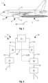
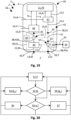
- Fig. 2 shows a schematic illustration of an energy conversion arrangement 10 of the energy system 2 of the aircraft 1.
- the energy conversion arrangement 10 comprises a fuel conversion device 11, for example, provided as a fuel cell system for converting hydrogen to electricity and predominantly water vapour as exhausts E of the fuel conversion.
- Air A for example taken from ambient surroundings, such as the atmosphere 7, and/or from inside the hull 4, e.g., from a cabin of the aircraft 1, is provided to the fuel conversion arrangement 11 through an air inlet 12 of the energy conversion arrangement 10.
- the exhausts E are released to the atmosphere 7 through an exhaust outlet 13 of the energy conversion arrangement 10.
- the air inlet 12 provides ambient air A to the compressing device 16 which supplies the fuel conversion device 11 with air A at an elevated pressure.
- the humid exhausts E e.g., exhaust air of the fuel cell system of the fuel conversion device 11 is expanded in the turbine to provide power to the compressor.
- a water vapour saturation line may be crossed and with a sufficiently high supersaturation, homogeneous nucleation may occur. This results in a large number of tiny exhaust droplets D E which grow through condensation (see Fig. 3 ).
- Fig. 3 shows a schematic illustration of the contrail reduction device 20 of the energy conversion arrangement 10 shown in Fig. 2 in operation.
- the contrail reduction device 20 comprises a pump 22 provided in the water supply line 21 to pressurise the water W and a spray nozzle 23 arranged in an air duct 25 to spray the water W into the exhausts E which may comprise droplets D E with the respective droplet diameter d DE of approximately below 1 ⁇ m by average before reaching the contrail reduction device 20.
- the liquid water W is provided to the spray nozzle 23 which creates water droplets Dw with an average diameter d DW larger than 20 micron.
- the smaller exhaust droplets D E coagulate on the larger water droplets Dw and thus form coagulated droplets C. Effectively, the droplet number is reduced and the average diameter d AVG is increased.
- the coagulated droplets C lead to less harmful contrails as their combined surface is smaller than a sum of the surfaces of the exhaust droplets D E and the water droplets Dw. Size and velocity of the water droplets Dw sprayed from the spray nozzle 23 must be chosen in a way that the critical Weber Number of about 12 is not surpassed. Otherwise, the water droplets Dw will break up into much smaller droplets, counteracting the desired effect.
- Fig. 4 shows another schematic duration of the contrail reduction device 20 of the energy conversion arrangement shown in Fig. 2 in operation.
- no exhaust droplets D E occur due to a lack of supersaturation of water vapour in the exhausts E. If the supersaturation before the contrail reduction device 20 is not sufficient for droplet formation, the contrail reduction device 20 can still reduce the risk for contrail formation. Without exhaust droplets D E , the water vapor in the plume 6 oversaturates during plume mixing outside of the aircraft 1. Again, a large number of droplets with small diameters will be formed through homogeneous nucleation.
- droplets generated in the contrail reduction device 20 either grow in a slightly oversaturated flow through condensation to form enlarged water droplets D'w or, in an unsaturated flow, are still large enough to persist when emitted from the aircraft 1.
- these pre-existing droplets Dw, D'w may provide phase boundaries for condensation which prevents high oversaturation and homogeneous nucleation. This leads to a small number of large droplets D'w instead of a large number of small droplets Dw.
- Fig. 5 shows a schematic illustration of further embodiment of an energy conversion arrangement 10 comprising a contrail reduction device 20.
- the contrail reduction device 20 is arranged in the flow path 15 between the fuel conversion device 11 and the expansion device 17 which comprises a turbine 19 (see Fig. 6 ).
- Liquid water W provided by fuel conversion device 11 is injected into the flow path 15 of the exhausts W upstream of the expansion device 17 using the spray nozzle 23 as illustrated in Figs. 3 and 4 .
- the water droplets Dw begin to grow through condensation as soon as supersaturation is reached during expansion in the expansion device 17. Because of the phase change and the release of the latent heat, this limits the maximum supersaturation reached.
- a lower maximum supersaturation corresponds to a smaller nucleation rate of water droplets Dw. This number decrease is larger than the droplet number introduced by the spray nozzle 23. In total, the droplet spectrum is again shifted to fewer, larger droplets C, D'w. The freezing of less droplets leads to an optically "thinner” contrail, reducing its climate impact, as the combined droplet surface is smaller.
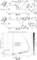
- Fig. 6 shows a schematic illustration of the expansion device 17 of the energy conversion arrangement 11 shown in Figs. 1 to 5 comprising the turbine 19.
- the water vapor in the plume 6 may oversaturate during plume mixing outside of the aircraft 1. Again, a large number of droplets with small diameters would be formed through homogeneous nucleation.
- Fig. 7 shows a schematic illustration of an expansion device 20 of the energy conversion arrangement shown in Figs. 1 to 6 with the turbine 19 and the contrail reduction device 20 in the flow path 15 of the exhausts E upstream of the turbine 19 in operation.
- the injection of water droplets Dw provides phase boundaries for condensation during expansion of the exhausts E within the turbine 19 which prevents high oversaturation and reduces or avoids homogeneous nucleation. This leads to a small number of large droplets C, D'w instead of a large number of small droplets D E .
- the injected water droplets Dw should be as small as possible. The larger the injected combined droplet surface is, the stronger is the reduction of the maximum supersaturation and nucleation rate.
- Injecting water droplets Dw in front of the turbine 19 may pose a risk of droplet erosion, corrosion, and other damages because of liquid water W.
- respective mitigation measures are well known from steam turbine research.
- Another option is to operate the contrail reduction device 20 in any of the embodiments described herein only when there is a risk of contrail formation. However, there might also be an efficiency improvement for the turbine 19 due to reduced phase change losses when operating the contrail reduction device 20.
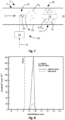
- the fact that the injection of water droplets Dw reduces the maximum nucleation rate is well known to science (see Fig. 8 ).
- the rate of nucleation decreases by the injection of water droplets Dw into the exhausts E.
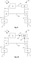
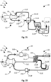
- Fig. 9 shows a schematic illustration of another embodiment of an energy conversion arrangement 10 provided with a heating device 30.
- the heating device 30 is located in the flow path 15 between the fuel conversion device 11 and the exhaust outlet 13.
- the heating device 30 is located in the flow path 15 of the exhausts E upstream of the expansion device 17.
- the exhausts E e.g., humid exhaust air from a fuel cell system of the fuel conversion device 11, is heated in the heating device 30.
- the heated exhausts E are being expanded in the expansion device 17, e.g., the turbine 19 thereof, to provide power to the compressing device 16 via the transmission line 18.
- the saturation increases during expansion in the expansion device 17.
- the saturation level is overall smaller due to the heating provided by the heating device 30.
- the heating device 30 can be placed in the flow path 15 downstream of the expansion device 17. This altogether prevents droplet formation or at least significantly reduces it. Fewer droplets pose a smaller risk to the formation of a dense contrail. A flow of exhausts E release to the atmosphere 7 with no or few droplets might still lead to droplet formation in the plume 6 outside of the aircraft 1. However, this is still expected to be beneficial as in this process the maximum achieved saturation level is assumed to be smaller than without heating. A smaller maximum saturation level corresponds with fewer, larger droplets C, D'w.
- Fig. 10 shows a schematic illustration of the energy conversion arrangement 10 shown in Fig. 9 where the heating device 30 comprises a catalytic converter 31.
- the catalytic converter 31 for example provided as a catalytic burner, can process leftover fuel, e.g., hydrogen from a fuel cell reaction performed in the fuel conversion device 11. The fuel reacts with oxygen to water while releasing heat. The added heat overcompensates the saturation increase due to the added water W.
- the catalytic burner also prevents fuel emissions from the energy conversion arrangement 10.
- Sensors 32 may be provided measure a fuel concentration in the flow path 15 of the exhausts E before and/or after the catalytic burner 31. Additional fuel B can be added to the flow path 15 of the exhausts E upstream of the catalytic burner 31 (see Fig. 11 ).
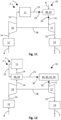
- Fig. 11 shows a schematic illustration of the energy conversion arrangement shown in Figs. 9 and 10 where the heating device 30 comprises a combustion chamber 33. depicts a fuel cell system with a combustion chamber which burns hydrogen.
- the additional fuel B reacts with oxygen, for example in that hydrogen added as additional fuel B reacts water W, while releasing heat.
- the added heat overcompensates the saturation increase due to the added water W.
- the combustion also prevents fuel emissions from the energy conversion arrangement 10.
- Fig. 12 shows a schematic illustration of the energy conversion arrangement 10 shown in Figs. 9 to 11 where the heating device 30 comprises a heat exchange device 34.
- the heat exchange device 30 adds heat to the exhausts E of the fuel conversion device 11 and thereby reduces the saturation before the expansion device 17.
- the contrail reduction device 20, heating device 30, catalytic converter 31, sensors 32, and/or combustion chamber 33 may be provided in the flow path 15 of the exhausts E before, within, and/or after the expansion device 17.
- Heat not transferred from the outflow of the compressing device in the flow path 14 of the air A may be gained from other heat sources of the fuel conversion system 10, in particular from a thermal management system 40 which may comprise multiple heat exchange devices 30 and/or heat exchange elements (see Fig. 14 ).
- Fig. 13 shows a schematic illustration of the energy conversion arrangement 10 shown in Figs. 9 to 12 where the heating device 30 comprises an electric heating element 35.
- the heating element 35 may provide electric heating to reduce contrail formation. The added heat reduces the saturation before the expansion device 17. Electric power may be provided to the heating element 35 by means of the transmission line 18 from the fuel conversion device 11 and/or from other sources (not shown).
- the energy conversion arrangement 10 may comprise a bypass duct 36 connecting to the flow path 15 of the exhausts E via a flow junction 37.
- the flow junction 37 may comprise a switch valve 38 which, for example, may be operated in a stepless manner, to let the exhausts E through to the expansion device 17 and/or lead the exhausts E to the exhaust outlet 13 via the bypass duct 36.
- the switch valve 38 may be operated with the help of a control unit 39 which may be connected to at least one of the sensors 32 via respective transmission line 18 for transmitting energy and/or information.
- the exhausts E may be branched off from the flow path 15 at the flow junction 37 to bypass the expansion device 17 through the bypass duct 36, thereby forming an alternate or auxiliary flow path 15 for the exhausts E in addition to the main flow path 15 of the exhausts E leading through the expansion device 17.
- the amount of exhausts E bypassing the expansion device 17 may be controlled by means of the control unit 39 in order to keep any measurement value, such as a temperature value, a pressure value, and/or a humidity value, measured by means of at least one of the sensors 32 before, within, and/or after the expansion device 17 within, above, and/or below a respective desired or required value range and/or limit.
- the flow junction 37 maybe arranged within the expansion device 17, for example, between certain sections thereof.
- the flow path 15 leading through the expansion device 17 and the flow path 15 leading through the bypass duct 36 may be joined within and/or after the expansion device 17 and/or the exhaust outlet 13.
- the bypass duct 36 may be used to bypass any section or component of the energy conversion arrangement 10 as described herein. Therefore, at least one flow junction 38 may be arranged as desired or required for bypassing the expansion device 17, the control reduction device 20, the heating device 30, and/or the heat exchange device 34.
- Fig. 14 shows a schematic illustration of a thermal management system 40 of any of the embodiments of an energy conversion arrangement 10 shown herein.
- the thermal management system 40 may emit further exhausts G, such as air and/or gases which preferably have a higher temperature and/or less relative humidity than the exhausts E.
- the further exhausts G can be released from the aircraft 1 by being emitted beyond the hull 4 in travel direction F before the exhausts E in the travel direction F.
- the exhausts E can have passed through an air supply system 41 comprising the compressing device 16, expansion device 17, heating device 30, and/or heat exchange device 34.
- Respective exhaust outlets 13 for the exhausts E and the further exhausts G may provide a mixing assembly 42.
- the thermal management system 40 can receive further air H from the atmosphere 7 and/or from inside the hull 4.
- the further air H may be used in the thermal management system 40 to cool down a coolant K which is then supplied to the fuel conversion device 11 in order to maintain a desired temperature level for efficient fuel conversion in the fuel conversion device 11.
- the coolant K may then be that back to the thermal management system 40.
- the further air H can be warmed up by means of the coolant K from the fuel conversion device 11.
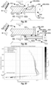
- Fig. 15 shows a schematic diagram showing plume 6 mixing lines in the atmosphere 7 represented by respective water vapor partial pressure as a function of the temperature.
- the narrow solid curve (line V) is the saturation pressure with regards to liquid water
- the dashed line X represents the mixing of the humid exhaust E air at point III with the atmospheric air at point IV.
- Point II is the result of the mixing of the humid exhaust air (point III) and the warm, dry flow (point I).
- the mixing process between these two flows is represented by the dotted line Y.
- the thick solid line Z represents the mixing line between the mixed exhaust state (point II) and the ambient air (point IV).
- Fig. 16 shows a schematic diagram of relative humidity within a plume 6 while mixing in the atmosphere 7.
- the solid line R on Figure 2 represents the evolution of a relative humidity R of the plume 6 as the exhausts E and further exhausts G (points III and I, respectively) mix with air under ambient atmospheric conditions (point IV).
- the mixing line R solid line
- the mixing line S dashed line
- the maximum supersaturation is much smaller than without the contrail reduction solution. This means that less droplets are formed and less condensation occurs, resulting in a reduced contrail formation and climate risk.
- the goal is to reduce the gradient of the mixing line S. The warmer, drier, and higher mass flow of the further exhaust G is, the stronger is the effect.
- FIG. 1 For alternative and/or additional embodiments of the presented solution may involve different air supply architectures, such as blowers instead of compressors, air from cabin instead of from ambient, nozzle instead of and/or in addition to turbine 19, electric motor on a shaft between compression device 16 and turbine 19, humidifiers, dehumidifiers, heat exchangers, etc.
- Different sources of liquid water W may be used, namely from a tank, from cabin systems, from a water separation device downstream of any point of the thermal management system 40 and/or air supply system 41.
- Multiple spray nozzles 23, or other means of generating disperse liquid water W may be located inside of the turbine 19 and/or inside of the fuel conversion device 11.
- Sensors 32 may be applied to measure ambient conditions and/or to measure condensation and droplet sizes in the energy conversion arrangement 10.
- sensors 32 may be used to measure contrail occurrence and effectiveness of the contrail reduction device 20.
- Controls may be used to adapt the spray flow for different droplet sizes, constant-mode, active-mode, etc.
- Heating and/or cooling devices 30 may be used to adapt the liquid water temperature in order to reach a smaller droplet size.
- Fig. 17 shows a schematic side view of aircrafts 1, a satellite 8 and a control station 9 configured for monitoring and/or controlling properties of a plume 6 of exhausts during flight of at least one of the aircrafts 1, in particular, with regard to at least one contrail formation parameter P of exhausts, the plume 6 and/or the atmosphere 7.
- the satellite can 8 be orbiting in space and monitor the aircrafts 1 and their plumes 6.
- the ground station 9 can be positioned on the ground g.
- the aircrafts 1, satellite 8 and/or ground station 9 may be connected to, provide and/or each comprise the control system 50 and/or a computer system 51 configured to perform monitoring and control functions for and/or in connection with operation of the energy system 2 of the aircraft 1.
- the aircrafts 1, satellite 8 and/or ground station 9 may comprise and/or be connected to at least one computing device 51, at least one control device 54 and/or at least one control element 59 (see Fig. 18 ). Thereby, individually, and/or in conjunction with each other, the aircrafts 1, satellite 8 and/or ground station 9 may keep and/or bring the at least one contrail formation parameter P out of at least one potential impact region of the contrail formation range indicative of a potential contrail impact to be avoided.
- the aircrafts 1, satellite 8 and/or ground station 9 may communicate with each other via respective communication channels c, for example, configured for digitally exchanging data for operating the control system 50.
- Fig. 18 shows a schematic top view of an aircraft 1 comprising a control device 54 for monitoring and controlling properties a composition of exhausts E, further exhausts G and/or an exhausts mix M.
- the aircraft 1 further comprises a fuel storage system 52 for providing fuel B to at least one energy conversion arrangement 10 of the aircraft 1 configured to provide electrical power e to the aircraft 1, for example, to propulsion units 5 and/or an energy storage system 53, such a battery, thereof.
- the control device 54 for controlling the operation of the vehicle 1, energy system 2, propulsion units 5, fuel conversion arrangement 10, and/or fuel conversion device 11 can be provided as a part of the vehicle 1 and/or can be at least partly integrated into the fuel conversion arrangement 10 itself.
- the control device 54 can comprise a processing unit 56, an interface module 57, a storage module 58 and/or the control element 59 which can be connected to each other via the respective communication lines 55 which may be configured to transfer any kind of information, data, power and/or energy.
- the vehicle 1 and/or the energy conversion arrangement 2 can be provided with a computing device 60 that may comprise the control device 54 or vice versa.
- a control program 61 for example, in the form of a computer program, can be stored on a computer-readable data carrier 62 which may take the form of a computer-readable medium 63 and/or data carrier signal 64.
- the control device 54 may comprise the computing device 60, the computer program 61, the computer-readable data carrier 62, and/or any kind of control element as well as communication lines 55 for exchanging data between the respective above-mentioned components.
- Control elements 59 may be any kind of data source and/or sink, such as a measuring element, sensor 32, control unit 39, output device and/or actuator of the vehicle 1, the energy conversion arrangement 2 and/or the propulsion units 5 which may constitute a part of the control system 50 for controlling a certain function thereof, for example, by connecting to the control elements 59 through the interface module 54.
- the aircraft 1 and/or energy system 2 may comprise multiple fuel cell systems 70 which may each comprise multiple fuel cell units 71 which may be used for generating electrical energy e for propulsion of the aircraft 1 and/or for powering auxiliary systems of the aircraft, such as an auxiliary power unit (APUs), and which may be stored in the energy storage system 53.
- the fuel cell system 70 may comprise and/or may be comprised of at least one fuel cell unit 71 containing multiple fuel cell elements 72 which may be a single fuel cell that can constitute a respective smallest controllable element of the fuel cell unit 71.
- the fuel cell units 71 may be provided, for example, in the form of fuel cell stacks. Each fuel cell unit 71 may comprise multiple fuel cell elements 72.
- the exhausts E may be mixed with further exhausts G from the thermal management system 40 in a controlled manner to obtain an exhausts mix M of the exhaust the and the further exhausts G.
- the exhausts mix M may emitted through a respective exhaust outlet 13 of the mixing assembly 42 beyond the hull 4 of the aircraft.
- the thermal management system 40 can receive further air H from the atmosphere 7 and/or from inside the hull 4.
- the further air H may be used in the thermal management system 40 to cool down a coolant K which is then supplied to the fuel conversion device 11 and/or the fuel cell system 70 in order to maintain a desired temperature level for efficient fuel conversion in the fuel conversion device 11 and/or fuel cell system 70.
- the coolant K may then be transported back to the thermal management system 40.
- the further air H can be warmed up by means of the coolant K from the fuel conversion device 11 to provide the further exhausts G.
- the mixing assembly 42 comprises a mixing device 44 which can be arranged within the hull 4.
- the first control valve 43a can be arranged in the flow path 15 of the exhausts E after the air supply system 41.
- the second control valve 43b may be provided in the flow path 15 of the further exhausts G after the thermal management system 40 in order to branch-off and/or divert the exhausts E before and/or when reaching the mixing device 44 and/or exhaust outlet 13 to be admixed to the exhausts E at a respective flow junction 37.
- Respective sensors 32 may be provided in the flow path 15 of the exhaust E before and/or after the respective flow junction 37 and/or control valve 43 in each case, as well as after the mixing assembly 44 and/or at any exhaust outlet 13.
- the mixing can be achieved by operating the first control valve 43a and/or the second control valve 43b to provide respective mixing ratios Q, such as a first mixing ratio Q a and/or a second mixing ratio Q b , representing an amount of exhausts E admixed to the further exhausts G and/or an amount of further exhausts G admixed to the exhausts E, respectively.
- respective mixing ratios Q such as a first mixing ratio Q a and/or a second mixing ratio Q b , representing an amount of exhausts E admixed to the further exhausts G and/or an amount of further exhausts G admixed to the exhausts E, respectively.
- the mixing ratios Q can be defined as a ratio having the amount of further exhausts G as a nominator and the amount of exhausts E as a denominator and can be kept zero, or at least essentially near zero, if the exhausts E of the fuel cell system 70 are out of the at least one potential impact region of the contrail formation range. Respective amounts of exhausts E admixed to the further exhausts G and/or an amount of further exhausts G admixed to the exhausts E can be held below a mixing threshold I which may indicate a limitation of the respective mixing ratios Q.
- step S2 it may be returned to step S1 in order to create a control loop for continuously monitoring the contrail formation parameter P in order to assess whether any of the mixing processes are necessary to keep and/or bring the at least one contrail formation parameter P out of at least one potential impact region of the contrail formation range indicative of a potential contrail impact to be avoided.
- a fifth step S5 be assessed whether an output of energy e of the fuel cell system 70 should be increased, for example, in order to elevate a temperature value T of the exhausts E and/or the further exhausts G.
- the fuel cell system 70 can be controlled such that its output of energy e should be increased to keep and/or bring the at least one contrail formation parameter P out of at least one potential impact region of the contrail formation range indicative of a potential contrail impact to be avoided.
- the fuel cell system 70 can be controlled such that the at least two fuel cell elements 72 are being operated each at a different current density to keep and/or bring the at least one contrail formation parameter P out of at least one potential impact region of the contrail formation range indicative of a potential contrail impact to be avoided.
- any of the steps S3, S4, S6 and S7 for mixing the exhausts E, G, and/or increasing an energy output of the fuel cell system 70, respectively, can be combined with each other as desired as or required for keeping asset or bringing the at least one contrail formation parameter P out of at least one potential impact region of the contrail formation range indicative of a potential contrail impact to be avoided.
- steps S6 and/or S7 are or is, respectively, applied in order to provide respective additional energy e output and/or rise of the temperature value T and thus an increased heat flow and/or output to enhance the result of any of the respective mixing processes, for example, in order to reduce a relative humidity of the exhausts E, the further exhausts G, and/or the exhausts mix M.
- the described method enables a control mechanism to either allow for a mixing of the TMS (further exhausts G exiting the TMS) and ASP (exhausts E exiting the ASP) outflows, i.e., and/or two separate outflows.
- the mixing can be selectively conducted during contrail forming conditions.
- any thermodynamic losses caused by the mixing process occur only when necessary.
- the accurate prediction for contrail forming conditions can be carried out in each of the steps of the method, in particular, in step S1 when monitoring the at least one contrail formation parameter P. This can be achieved by sensors 32 and/or control elements 59 on the aircraft 1 and/or by information provided from external sources, such as other aircraft 1, satellites 8 and/or ground stations 9.
- steps S5, S6 and/or S7 allow for adding a controlled amount of heat to the exhausts, for example in the form of TMS outflow to the ASP outflow. This would allow to control the droplet formation in the ASP outflow. Adding heat reduces the relative humidity and hence delays the formation of droplets. Not adding heat promotes droplet formation. Depending on the outflow aerodynamics, an enhanced or delayed droplet formation reduces or increases the final droplet number and droplet size. This adds another degree of freedom and provides control of contrail properties.
- Fig. 21 shows a schematic illustration of an exemplary embodiment of an energy conversion arrangement 10 comprising a humidifying device 130 having at least one humidifying stage 131, 132 (see also Fig. 16 ).
- the energy conversion arrangement 10 may further comprise an intercooler assembly 140, and/or at least one filter device 150 which may have at least one particle filter element 151 and/or chemical filter element 152.
- the energy conversion arrangement 10 may comprise at least one water separator 210.
- the humidifying device 130 is arranged in a flow path 14 of the supply air A and a flow path 15 the exhausts E.
- the humidifying device 130 is configured to humidify the supply air A with water W from the exhausts E.
- the humidifying device 130 is arranged between the intercooler assembly 140 and the fuel conversion device 11, in particular, the fuel cell system 70, in the flow path 14 of the supply air A, and/or between the intercooler assembly 140 and the water separator 210 in the flow path 15 of the exhausts E, respectively.
- the intercooler assembly 140 may comprise at least one heat exchange unit 34.
- the intercooler assembly 140 may be arranged in the flow path 14 of the supply air A between the humidifying device 130 and the filter device 150, and/or the flow path 15 of the exhausts E between the humidifying device 130 and the air supply system 41, in particular the turbine 19 thereof.
- the at least one filter device 150 may be arranged in the flow path 14 of the supply air between the air inlet 12 and the air supply system 41, in particular the compressing device 16, thereof, and/or between the air supply system 41, in particular the compressing device 16, thereof, and the intercooler assembly 140, respectively.
- the humidifying device 130 can be used as a water separator.
- the humidifying device 130 may have a separation structure comprising a permeable membrane and/or absorbent material.
- the permeable membrane may be provided in the form of an/or comprise a capillary assembly or pore arrangement which can be configured to maximise a separation surface provided by the permeable membrane. Therefore, the capillary assembly may comprise a number of capillary elements and/or pores forming guide channels for separating water W from the exhausts E. Due to respective small flow channels, the humidifying device 130 may filter tiny droplets from the flow, in particular, if it is placed downstream of the turbine 19. The tiny droplets may condense in the turbine 19 and can be difficult to separate otherwise from the exhausts E otherwise.
- the supply air A can be sucked in through the air inlet 12 from the atmosphere 7 and/or from inside the hull 4, e.g., from a cabin of the aircraft 1.
- the supply air A may then pass the at least one filter device 150 in order to filter out any undesired particles and/or chemical components from the supply air A.
- the supply air A may pass the air supply system 41, in particular the compressing device 16, in order to be pressurised to a desired degree.
- the pressurised supply air A may then (again) pass the at least one filter device 150 in order to filter out any undesired particles and/or chemical components from the supply air A.
- the supply air A may be cooled down through a corresponding heat exchange with the exhausts E.
- the relatively dry supply air A can then pass the humidifying device 130 in order to be humidified with water W from the exhausts E (liquid water and/or water vapour).
- the supply air A and the exhausts E can at least section -wise be guided in a counterflow arrangement in the humidifying device 130.
- the supply air A can be supplied to the fuel conversion device 11, in particular the fuel cell system 70.
- the exhausts E from the fuel conversion device 11, in particular the fuel system 70, can be led through the water separator 210, where water W can be separated from the exhausts E and can be led away through a respective water supply line 21, and/or piping.
- the exhausts E can then pass the humidifying device 130.
- the exhausts E can be led through the intercooler assembly 140 and then through the air supply system 41, in particular the turbine 19, thereof.
- the exhausts E may be then led to the exhaust outlet 13 and/or to a missing assembly 42 or alike.
- sensors 32 can be provided at the air inlet 12, the exhaust outlet 13, for the flow path 14 of the supply air A entering the fuel conversion device 11, in particular the fuel cell system 70, and/or any location in between in order to be able to adjust a humidity of the supply air A and/or the exhausts E based on at least one measurement value to provide humidity control for the fuel conversion device 11, by means of the control device 54 of the control system 50.
- the humidifying device 130, the intercooler assembly 140, and/or the at least one filter device 150 may be regarded as a part of the thermal management system 40 and/or the air supply system 41, effectively. As such, any part of components of the humidifying device 130, the intercooler assembly 140, and/or the at least one filter device 150 can be used separately and/or in conjunction with any other configuration and/or exemplary embodiment of the energy conversion arrangement 10 described herein.
- Fig. 22 shows a schematic illustration of another exemplary embodiment of an energy conversion arrangement 10 comprising a humidifying device 130.
- the humidifying device 130 may be operated such that the supply air A and the exhausts E are at least section-wise guided in a crossflow arrangement.
- the intercooler device 140 may be cooled as desired or required by further air H and/or the exhausts E leaving the humidifying device 130, and/or maybe integrated into the filter device 150 or vice versa.
- a particle filter element 151 may be arranged in the flow path 14 of the supply air A between the air supply system 41, in particular the compressing device 16, thereof, and the intercooler assembly 140, in particular, in order to remove unwanted particles from the supply air A.
- a chemical filter element 152 may be arranged in the flow path 14 of the supply air A between the intercooler assembly 140 and the humidifying device 130, in particular, in order to remove unwanted components from the supply air A.
- the intercooler device 140, particle filter element 151 and/or chemical filter element 152 can be arranged back-to-back with respect to each other.
- Fig. 23 shows a schematic illustration of a further exemplary embodiment of an energy conversion arrangement 10 comprising a humidifying device.
- the humidifying device 130 may be operated such that the supply air A and the exhausts E are at least section-wise guided in a counter-flow and/or crossflow arrangement.
- the two humidifying stages 131, 132 may be provided in the humidifying device 130.
- a first humidifying stage 131 and a second unifying stage 132 may be provided.
- the supply air A from the intercooler assembly 140 and/or the filter device 150 may be humidified by means of the exhausts the from the air supply system 41, in particular the turbine 19 thereof.
- the supply air from the first humidifying stage 131 may be humidified by means of the exhausts E from the fuel conversion device 11, in particular the fuel cell system 70, for example after leaving the water separator 210.
- Fig. 24 shows a schematic illustration of another further exemplary embodiment of an energy conversion arrangement comprising a humidifying device.
- the first humidifying stage 131 and a second unifying stage 132 may be separated from each other in that the exhausts E leave the humidifying device 130 after the first humidifying stage 131 and are then being fed into the air supply system 41, in particular the turbine 19, thereof. After leaving the turbine 19, the exhausts E are led into the second humidifying stage 132. After the second humidifying stage 132, the exhaust E can be led through the intercooler assembly 140 and then towards the exhaust outlet 13.
- Fig. 25 shows a schematic illustration of an exemplary embodiment of an energy conversion arrangement 10 comprising a water separator 210 or water separation device.
- the arrangement 10 comprises at least one water separator 210 arranged in a flow path 15 of exhausts E produced in the fuel conversion device 11 and configured for separating water W from products of the fuel conversion device 11 on their way from the fuel conversion device 11 to the exhaust outlet 13.
- the water W withdrawn from the exhausts E can be led through the respective water supply line 21 and/or piping.
- the water W withdrawn from the exhaust E can be discharged through the water supply line 21 from the aircraft 1 and/or be led to the contrail reduction device 20.
- the materials separator 210 may partially or fully separate the gaseous or liquid water W which can then be drained. Drained water W, for example, in the form of large droplets, cannot contribute to contrail formation.
- the water separating materials in the water separator 210 may cause a pressure loss which reduces the power potential of a turbine 19 as or as a part of the expansion device 17.
- the energy conversion arrangement 10 and any of the energy conversion arrangements described herein may comprise a motor 300, for example, an electric motor, or alike, which may be configured to compensate for any energetic losses incurred upstream of the water separator 210 by the water separation, in particular, in that the motor 300 may drive the compressing device 16 in addition to the expansion device 17, such as the turbine 19.
- the motor 300 can be arranged and/or adapted to transfer power onto the transmission line 18, which may at least in part be configured as a driveshaft driven by the motor 300.
- Fig. 26 shows a schematic illustration of another exemplary embodiment of an energy conversion arrangement comprising a water separator 210.
- the energy conversion arrangement 10 may comprise a bypass duct 36 connecting to the flow path 15 of the exhausts E via a flow junction 37, wherein the at least one water separator 210 is arranged in the bypass duct 36.
- the flow junction 37 may comprise a switch valve 38 which, for example, may be operated in a stepless manner, to let the exhausts E through to the expansion device 17 and/or lead the exhausts E to the exhaust outlet 13 via the bypass duct 36.
- the switch valve 38 may be operated with the help of a control unit 39 which may be connected to at least one of the sensors 32 via respective transmission line 18 and/or communication line 55 for transmitting energy and/or information.
- operation of the switch valve 38 may be controlled by means of the control system 50, in particular the control device 54, to provide a control valve 43 for controlling an amount of exhausts E led through the bypass duct 36 to the water separator 210.
- the exhausts E may be branched off from the flow path 15 at the flow junction 37 to bypass the expansion device 17 through the bypass duct 36 leading to the water separator 210, thereby forming an alternate or auxiliary flow path 15 for the exhausts E in addition to the main flow path 15 of the exhausts E leading through the expansion device 17.
- the amount of exhausts E bypassing the expansion device 17 and led through the water separator may be controlled by means of the control unit 39 and/or the control system 50, in particular the control device 54, in order to keep any measurement value, such as a temperature value, a pressure value, and/or a humidity value, measured by means of at least one of the sensors 32 before, within, and/or after the expansion device 17 within, above, and/or below a respective desired or required value range and/or limit.
- any measurement value such as a temperature value, a pressure value, and/or a humidity value
- the flow junction 37 may be arranged within the expansion device 17, for example, between certain sections thereof.
- the flow path 15 leading through the expansion device 17 and the flow path 15 leading through the bypass duct 36 may be joined within and/or after the expansion device 17 and/or the exhaust outlet 13.
- the bypass duct 36 may be used to bypass any section or component of the energy conversion arrangement 10 as described herein. Therefore, at least one flow junction 38 may be arranged as desired or required for bypassing the expansion device 17, the contrail reduction device 20, the heating device 30, and/or the heat exchange device 34.
- Fig. 27 shows a schematic illustration of a further exemplary embodiment of an energy conversion arrangement 10 comprising a water separator 210.
- the water separator 210 is arranged upstream of the expansion device 17, in particularly the turbine 19. Thereby, relative humidity of the exhausts E entering the expansion device 17, in particular turbine 19, may be reduced to such a degree, that condensation of water W in the expansion device, in particular turbine 19, may be avoided.
- Fig. 28 shows a schematic illustration of another further exemplary embodiment of an energy conversion arrangement 10 comprising a water separator 210.
- the water separator 210 is arranged in the flow path 15 of the exhausts E instead of and/or as the expansion device 17.
- the pressure drop in the exhausts E within the water separator 210 may be utilised to foster the separation process.
- Fig. 29 shows a schematic perspective semi-transparent view of a water separator 210 (see Bocciardo, Davide, "Optimisation and integration of membrane processes in coal-fired power plants with carbon capture and storage", 2015, https://www.researchgate.net/publication/292788149 _ Optim isation_and_integra tion of membrane_processes_in coal-fired_power_plants_with_carbon_capture_and_storage ).
- the at least one water separator 210 may have at least one exhaust inlet 211, at least one wet outlet 212, and/or at least one dry outlet 213, which, for example, may be provided at an enclosure 214, such as a housing or piping of the water separator 210.
- the enclosure 214 may at least partly provide the flow path 15 for the exhausts E and comprises a separation structure 215 extending along the flow path 15 for the exhausts E provided by the water separator 210.
- the separation structure 215 comprises a permeable membrane 216 and/or absorbent material.
- the permeable membrane 216 may be provided in the form of an/or comprise a capillary assembly 217 or pore arrangement which can be configured to maximise a separation surface provided by the permeable membrane 216. Therefore, the capillary assembly 217 may comprise a number of capillary elements 218 and/or pores forming guide channels for separating water W from the exhausts E.
- the exhausts E can enter the water separator 210 through the exhaust inlet 211 and are travelling along the separation structure 217, for example through the capillary elements 218, thereof, such that water W contained in the exhausts E can fuse through the permeable membrane 216, why the remaining relatively dry exhausts E travel to the dry outlet 213 where they can be discharged from the water separator 210.
- the collected water W can be discharged through the wet outlet 212 which can be connected to the water supply line 21 or piping.
- the water separator 210 containing the water separating materials can be placed at any location of the energy conversion arrangement 10 where the flow of exhausts E has the highest or at least a relatively high content of liquid water and/or water vapor. This supports the separation processes. Further, the separating materials making up the separation structure 215 do not have to be concentrated in one single water separation component, such as the water separator 210. They can also be incorporated in the pipe walls and all other component surfaces of the energy conversion arrangement 10 which are in contact to a relatively humid flow of exhausts E. An important, if not the most important factor for the effectiveness of the used material can be seen in the respective water flux per surface area of the permeable membrane to 16. The available surface area should be maximized, for example by filling the volume of the flow path with hollow fibres, capillary tubes, narrow tubes, or alike, which can be arranged as a respective capillary assembly 217.
- Fig. 30 shows a schematic illustration of a model for an embodiment of an exhaust assembly 400 of an energy conversion arrangement 10.
- the exhaust assembly 400 can comprise a wall portion 401 which can provide an outer wall section 402 and an inner wall section 403.
- a lip 404 can be arranged between the outer wall section 402 and the inner wall section 403.
- the inner wall section 403 may at least partly define a flow path 15 for the exhausts E, in particular an outlet passage 405 thereof, leading to an exhaust outlet 13 for letting out the exhausts E into the atmosphere 7 which can be regarded as bordering the mixing assembly 400.
- the mixing assembly 400, in particular the outlet passage 405 is illustrated as having an optional symmetry plane s. Asymmetric configurations of the mixing assembly 400 can be implemented as desired or required.
- a mixing zone 406 is formed in the vicinity and/or around the lip 404 at the exhaust outlet 13.
- Fig. 31 shows a schematic illustration of a model of the mixing zone 406 created by an embodiment of an exhaust assembly 400 as illustrated in Fig. 30 .
- a droplet source 407 of relatively large droplets C formed of water vapour contained in the exhausts E may be established in the mixing zone 406 under certain operating and/or atmospheric conditions.
- Formation of the droplets C can be fostered by providing trailing edges, for example, an outer trailing edge 408 between the outer wall section 402 and the lip 404 for the flow of ambient air A resulting from a certain flight speed in the travel direction F, and/or an inner trailing edge 409 between the inner wall section 403 and the lip 404 for the flow of exhausts E, which may help to create a recirculation region 410 in the mixing zone 406.
- trailing edges for example, an outer trailing edge 408 between the outer wall section 402 and the lip 404 for the flow of ambient air A resulting from a certain flight speed in the travel direction F, and/or an inner trailing edge 409 between the inner wall section 403 and the lip 404 for the flow of exhausts E, which may help to create a recirculation region 410 in the mixing zone 406.
- the recirculation region 410 may comprise an air vortex 411 at least partly driven by ambient air A and/or an exhaust vortex 412 of exhausts E at least partly driven by the exhausts E.
- the outer trailing edge 408 and/or the inner trailing edge 409 promotes formation of the air vortex 411 and/or the exhaust vortex 412, respectively.
- the recirculation region 410 can build, where respective streams of ambient air A exhausts E, and/or a mix thereof at least in parts are reversed and thus may flow essentially in parallel to the travel direction F.
- the recirculation region 410 can comprise and/or can be comprised of the air vortex 411 and/or the exhaust vortex 412.
- the ambient air A can gradually mix with the exhausts E to promote formation of relatively large droplets C which may create the plume 6.
- variable lip height h L is set to values between 1 mm and 5 mm for the non-recirculation and recirculation cases, respectively.
- the outlet lengths l 13 is set to 70 mm. Resulting values for droplet formation parameters of the simulation illustrated in Fig. 34 are generated at the outlet of the simulated domain at a distance of approx. 15 m away from the respective exemplary embodiment of the exhaust assembly 400.
Landscapes
- Engineering & Computer Science (AREA)
- Chemical & Material Sciences (AREA)
- Aviation & Aerospace Engineering (AREA)
- Sustainable Development (AREA)
- Sustainable Energy (AREA)
- Life Sciences & Earth Sciences (AREA)
- Chemical Kinetics & Catalysis (AREA)
- Electrochemistry (AREA)
- General Chemical & Material Sciences (AREA)
- Manufacturing & Machinery (AREA)
- Combustion & Propulsion (AREA)
- Mechanical Engineering (AREA)
- Fuel Cell (AREA)
Applications Claiming Priority (6)
| Application Number | Priority Date | Filing Date | Title |
|---|---|---|---|
| EP23290050.6A EP4574660A1 (de) | 2023-12-21 | 2023-12-21 | Energieumwandlungsanordnung, energiesystem und flugzeug damit |
| EP23290052.2A EP4574672A1 (de) | 2023-12-21 | 2023-12-21 | Energieumwandlungsanordnung, energiesystem und flugzeug damit |
| EP23290049.8A EP4574670A1 (de) | 2023-12-21 | 2023-12-21 | Energieumwandlungsanordnung, energiesystem und flugzeug damit |
| EP23290048.0A EP4574678A1 (de) | 2023-12-21 | 2023-12-21 | Energieumwandlungsanordnung und flugzeug damit |
| EP23290051.4A EP4574671A1 (de) | 2023-12-21 | 2023-12-21 | Energieumwandlungsanordnung, energiesystem und flugzeug damit |
| DE102024122543.2A DE102024122543A1 (de) | 2023-12-21 | 2024-08-07 | Energieumwandlungsanordnung, energiesystem und flugzeug mit einer solchen anordnung |
Publications (1)
| Publication Number | Publication Date |
|---|---|
| EP4574665A1 true EP4574665A1 (de) | 2025-06-25 |
Family
ID=93520897
Family Applications (2)
| Application Number | Title | Priority Date | Filing Date |
|---|---|---|---|
| EP24214240.4A Pending EP4574662A1 (de) | 2023-12-21 | 2024-11-20 | Energieumwandlungsanordnung, energiesystem und flugzeug damit |
| EP24221585.3A Pending EP4574665A1 (de) | 2023-12-21 | 2024-12-19 | Energieumwandlungsanordnung, energiesystem, antriebseinheit und flugzeug damit |
Family Applications Before (1)
| Application Number | Title | Priority Date | Filing Date |
|---|---|---|---|
| EP24214240.4A Pending EP4574662A1 (de) | 2023-12-21 | 2024-11-20 | Energieumwandlungsanordnung, energiesystem und flugzeug damit |
Country Status (1)
| Country | Link |
|---|---|
| EP (2) | EP4574662A1 (de) |
Citations (10)
| Publication number | Priority date | Publication date | Assignee | Title |
|---|---|---|---|---|
| US5005355A (en) | 1988-08-24 | 1991-04-09 | Scipar, Inc. | Method of suppressing formation of contrails and solution therefor |
| US20080072577A1 (en) * | 2006-05-05 | 2008-03-27 | Taylor Mark D | Gas turbine engine |
| EP2150692A2 (de) | 2007-05-26 | 2010-02-10 | Rolls-Royce plc | Verfahren und vorrichtung zur unterdrückung von flugzeugtriebwerkkondensstreifen |
| EP2153043A2 (de) | 2007-05-26 | 2010-02-17 | Rolls-Royce plc | Verfahren und vorrichtung zur unterdrückung von flugtriebwerk-kondensstreifen |
| US20210207500A1 (en) * | 2018-05-22 | 2021-07-08 | MTU Aero Engines AG | Exhaust-gas treatment device, aircraft propulsion system, and method for treating an exhaust-gas stream |
| EP3961012A1 (de) | 2020-09-01 | 2022-03-02 | Airbus Operations, S.L.U. | Vorrichtung und verfahren zur beurteilung von flugzeugflugkondensstreifen |
| WO2022212575A1 (en) * | 2021-03-31 | 2022-10-06 | Zeroavia Ltd. | Exhaust water vapor management for hydrogen fuel cell-powered aircraft |
| US11565607B2 (en) * | 2020-06-15 | 2023-01-31 | Joby Aero, Inc. | High efficiency hydrogen fueled high altitude thermodynamic fuel cell system and aircraft using same |
| US11579050B2 (en) | 2020-03-11 | 2023-02-14 | Airbus Sas | System for sampling and analyzing contrails generated by an aircraft |
| WO2023246980A1 (de) * | 2022-06-22 | 2023-12-28 | MTU Aero Engines AG | Antriebssystem für ein luftfahrzeug |
Family Cites Families (4)
| Publication number | Priority date | Publication date | Assignee | Title |
|---|---|---|---|---|
| DE102012222020B4 (de) * | 2012-11-30 | 2022-03-31 | Airbus Operations Gmbh | System zum Versorgen eines Flugzeugs mit Inertgas, Verfahren zum Versorgen eines Flugzeugs mit Inertgas, Verwendung einer Membran und Flugzeug |
| FR3068009B1 (fr) * | 2017-06-23 | 2023-09-15 | Zodiac Aerotechnics | Systeme d'inertage d'au moins un volume dans un aeronef via au moins une pile a combustible |
| FR3111477B1 (fr) * | 2020-06-11 | 2024-10-25 | Liebherr Aerospace Toulouse Sas | Système de refroidissement d’une pile à combustible et pile à combustible équipée d’un tel système |
| US12347896B2 (en) * | 2022-06-10 | 2025-07-01 | Zeroavia Ltd | Pumped two-phase fuel cell cooling |
-
2024
- 2024-11-20 EP EP24214240.4A patent/EP4574662A1/de active Pending
- 2024-12-19 EP EP24221585.3A patent/EP4574665A1/de active Pending
Patent Citations (11)
| Publication number | Priority date | Publication date | Assignee | Title |
|---|---|---|---|---|
| US5005355A (en) | 1988-08-24 | 1991-04-09 | Scipar, Inc. | Method of suppressing formation of contrails and solution therefor |
| US20080072577A1 (en) * | 2006-05-05 | 2008-03-27 | Taylor Mark D | Gas turbine engine |
| US7971438B2 (en) | 2006-05-05 | 2011-07-05 | Rolls-Royce Plc | Gas turbine engine having a heat exchanger arrangement for exhaust gas flows |
| EP2150692A2 (de) | 2007-05-26 | 2010-02-10 | Rolls-Royce plc | Verfahren und vorrichtung zur unterdrückung von flugzeugtriebwerkkondensstreifen |
| EP2153043A2 (de) | 2007-05-26 | 2010-02-17 | Rolls-Royce plc | Verfahren und vorrichtung zur unterdrückung von flugtriebwerk-kondensstreifen |
| US20210207500A1 (en) * | 2018-05-22 | 2021-07-08 | MTU Aero Engines AG | Exhaust-gas treatment device, aircraft propulsion system, and method for treating an exhaust-gas stream |
| US11579050B2 (en) | 2020-03-11 | 2023-02-14 | Airbus Sas | System for sampling and analyzing contrails generated by an aircraft |
| US11565607B2 (en) * | 2020-06-15 | 2023-01-31 | Joby Aero, Inc. | High efficiency hydrogen fueled high altitude thermodynamic fuel cell system and aircraft using same |
| EP3961012A1 (de) | 2020-09-01 | 2022-03-02 | Airbus Operations, S.L.U. | Vorrichtung und verfahren zur beurteilung von flugzeugflugkondensstreifen |
| WO2022212575A1 (en) * | 2021-03-31 | 2022-10-06 | Zeroavia Ltd. | Exhaust water vapor management for hydrogen fuel cell-powered aircraft |
| WO2023246980A1 (de) * | 2022-06-22 | 2023-12-28 | MTU Aero Engines AG | Antriebssystem für ein luftfahrzeug |
Non-Patent Citations (2)
| Title |
|---|
| H. CRUZ CHAMPIONS. KABELAC: "Multifunctional fuel cell system for civil aircraft: Study of the cathode exhaust gas dehumidification", INTERNATIONAL JOURNAL OF HYDROGEN ENERGY, vol. 42, 2017, pages 29518 - 29531, XP085249062, DOI: 10.1016/j.ijhydene.2017.09.175 |
| TEYMOURTASH ET AL.: "The effects of rate of expansion and injection of water droplets on the entropy generation of nucleating steam flow in a Laval nozzle", HEAT MASS TRANSFER, vol. 45, 2009, pages 1185 - 1198, XP019704148 |
Also Published As
| Publication number | Publication date |
|---|---|
| EP4574662A1 (de) | 2025-06-25 |
Similar Documents
| Publication | Publication Date | Title |
|---|---|---|
| US9614238B2 (en) | Fuel cell system | |
| CN104903193B (zh) | 用于航空器的空气调节方法和系统 | |
| EP4509398A1 (de) | Wärmeverwaltungssystem für ein brennstoffzellenflugzeug | |
| EP4512721A1 (de) | Flüssigwasserstoffzufuhrsystem für brennstoffzellenbetriebenes flugzeug | |
| EP4509409A1 (de) | Integration eines gondelluftwärmetauschers für ein mit wasserstoffbetriebener brennstoffzelle angetriebenes flugzeug | |
| US20060138280A1 (en) | Arrangement and method for utilizing the heat of waste air for heating the bilge area of aircraft | |
| EP4574660A1 (de) | Energieumwandlungsanordnung, energiesystem und flugzeug damit | |
| EP4574665A1 (de) | Energieumwandlungsanordnung, energiesystem, antriebseinheit und flugzeug damit | |
| CN108128465B (zh) | 飞机空调系统和用于操作飞机空调系统的方法 | |
| EP4574673A1 (de) | Energieumwandlungsanordnung, energiesystem und flugzeug damit | |
| EP4574661A1 (de) | Energieumwandlungsanordnung, energiesystem und flugzeug damit | |
| EP4574672A1 (de) | Energieumwandlungsanordnung, energiesystem und flugzeug damit | |
| EP4574678A1 (de) | Energieumwandlungsanordnung und flugzeug damit | |
| EP4574670A1 (de) | Energieumwandlungsanordnung, energiesystem und flugzeug damit | |
| EP4574671A1 (de) | Energieumwandlungsanordnung, energiesystem und flugzeug damit | |
| EP4574663A1 (de) | Energieumwandlungsanordnung, energiesystem und flugzeug damit | |
| EP4510250A2 (de) | Niedertemperatur-protonenaustauschmembran-ladeluftwärmetauscher | |
| EP4691913A1 (de) | Energieumwandlungsanordnung, energiesystem und flugzeug damit | |
| US20250206153A1 (en) | Energy conversion arrangement, energy system and aircraft comprising same | |
| US20250207538A1 (en) | Energy conversion arrangement, energy system and aircraft comprising same | |
| US20250206154A1 (en) | Energy conversion arrangement, energy system and aircraft comprising same | |
| EP4509408A2 (de) | Konfiguration für ein lh2-brennstoffzellenflugzeug mit verteilten systemen | |
| EP4509410A1 (de) | Gepumpte zweiphasenkühlung von flugzeugelektronik | |
| EP4510251A2 (de) | Start eines hochtemperatur-protonenaustauschmembran (htpem)-brennstoffzellenflugzeugs mit mehreren stromerzeugungseinheiten | |
| EP4484292A1 (de) | Klimaregelungssystem mit flüssigwasserstoffbrennstoffverdampfung für eine wasserstoffbrennstoffzelle |
Legal Events
| Date | Code | Title | Description |
|---|---|---|---|
| PUAI | Public reference made under article 153(3) epc to a published international application that has entered the european phase |
Free format text: ORIGINAL CODE: 0009012 |
|
| STAA | Information on the status of an ep patent application or granted ep patent |
Free format text: STATUS: THE APPLICATION HAS BEEN PUBLISHED |
|
| AK | Designated contracting states |
Kind code of ref document: A1 Designated state(s): AL AT BE BG CH CY CZ DE DK EE ES FI FR GB GR HR HU IE IS IT LI LT LU LV MC ME MK MT NL NO PL PT RO RS SE SI SK SM TR |
|
| STAA | Information on the status of an ep patent application or granted ep patent |
Free format text: STATUS: REQUEST FOR EXAMINATION WAS MADE |
|
| 17P | Request for examination filed |
Effective date: 20251219 |