EP4574673A1 - Energieumwandlungsanordnung, energiesystem und flugzeug damit - Google Patents
Energieumwandlungsanordnung, energiesystem und flugzeug damit Download PDFInfo
- Publication number
- EP4574673A1 EP4574673A1 EP24290028.0A EP24290028A EP4574673A1 EP 4574673 A1 EP4574673 A1 EP 4574673A1 EP 24290028 A EP24290028 A EP 24290028A EP 4574673 A1 EP4574673 A1 EP 4574673A1
- Authority
- EP
- European Patent Office
- Prior art keywords
- exhausts
- energy conversion
- contrail
- fuel
- conversion arrangement
- Prior art date
- Legal status (The legal status is an assumption and is not a legal conclusion. Google has not performed a legal analysis and makes no representation as to the accuracy of the status listed.)
- Pending
Links
Images


Classifications
-
- B—PERFORMING OPERATIONS; TRANSPORTING
- B64—AIRCRAFT; AVIATION; COSMONAUTICS
- B64D—EQUIPMENT FOR FITTING IN OR TO AIRCRAFT; FLIGHT SUITS; PARACHUTES; ARRANGEMENT OR MOUNTING OF POWER PLANTS OR PROPULSION TRANSMISSIONS IN AIRCRAFT
- B64D27/00—Arrangement or mounting of power plants in aircraft; Aircraft characterised by the type or position of power plants
- B64D27/02—Aircraft characterised by the type or position of power plants
- B64D27/30—Aircraft characterised by electric power plants
- B64D27/35—Arrangements for on-board electric energy production, distribution, recovery or storage
- B64D27/355—Arrangements for on-board electric energy production, distribution, recovery or storage using fuel cells
-
- B—PERFORMING OPERATIONS; TRANSPORTING
- B64—AIRCRAFT; AVIATION; COSMONAUTICS
- B64D—EQUIPMENT FOR FITTING IN OR TO AIRCRAFT; FLIGHT SUITS; PARACHUTES; ARRANGEMENT OR MOUNTING OF POWER PLANTS OR PROPULSION TRANSMISSIONS IN AIRCRAFT
- B64D33/00—Arrangement in aircraft of power plant parts or auxiliaries not otherwise provided for
- B64D33/04—Arrangement in aircraft of power plant parts or auxiliaries not otherwise provided for of exhaust outlets or jet pipes
-
- B—PERFORMING OPERATIONS; TRANSPORTING
- B64—AIRCRAFT; AVIATION; COSMONAUTICS
- B64D—EQUIPMENT FOR FITTING IN OR TO AIRCRAFT; FLIGHT SUITS; PARACHUTES; ARRANGEMENT OR MOUNTING OF POWER PLANTS OR PROPULSION TRANSMISSIONS IN AIRCRAFT
- B64D37/00—Arrangements in connection with fuel supply for power plant
- B64D37/30—Fuel systems for specific fuels
-
- B—PERFORMING OPERATIONS; TRANSPORTING
- B64—AIRCRAFT; AVIATION; COSMONAUTICS
- B64D—EQUIPMENT FOR FITTING IN OR TO AIRCRAFT; FLIGHT SUITS; PARACHUTES; ARRANGEMENT OR MOUNTING OF POWER PLANTS OR PROPULSION TRANSMISSIONS IN AIRCRAFT
- B64D41/00—Power installations for auxiliary purposes
-
- H—ELECTRICITY
- H01—ELECTRIC ELEMENTS
- H01M—PROCESSES OR MEANS, e.g. BATTERIES, FOR THE DIRECT CONVERSION OF CHEMICAL ENERGY INTO ELECTRICAL ENERGY
- H01M8/00—Fuel cells; Manufacture thereof
- H01M8/04—Auxiliary arrangements, e.g. for control of pressure or for circulation of fluids
- H01M8/04082—Arrangements for control of reactant parameters, e.g. pressure or concentration
- H01M8/04089—Arrangements for control of reactant parameters, e.g. pressure or concentration of gaseous reactants
- H01M8/04111—Arrangements for control of reactant parameters, e.g. pressure or concentration of gaseous reactants using a compressor turbine assembly
-
- H—ELECTRICITY
- H01—ELECTRIC ELEMENTS
- H01M—PROCESSES OR MEANS, e.g. BATTERIES, FOR THE DIRECT CONVERSION OF CHEMICAL ENERGY INTO ELECTRICAL ENERGY
- H01M8/00—Fuel cells; Manufacture thereof
- H01M8/24—Grouping of fuel cells, e.g. stacking of fuel cells
- H01M8/249—Grouping of fuel cells, e.g. stacking of fuel cells comprising two or more groupings of fuel cells, e.g. modular assemblies
-
- B—PERFORMING OPERATIONS; TRANSPORTING
- B64—AIRCRAFT; AVIATION; COSMONAUTICS
- B64D—EQUIPMENT FOR FITTING IN OR TO AIRCRAFT; FLIGHT SUITS; PARACHUTES; ARRANGEMENT OR MOUNTING OF POWER PLANTS OR PROPULSION TRANSMISSIONS IN AIRCRAFT
- B64D41/00—Power installations for auxiliary purposes
- B64D2041/005—Fuel cells
-
- H—ELECTRICITY
- H01—ELECTRIC ELEMENTS
- H01M—PROCESSES OR MEANS, e.g. BATTERIES, FOR THE DIRECT CONVERSION OF CHEMICAL ENERGY INTO ELECTRICAL ENERGY
- H01M2250/00—Fuel cells for particular applications; Specific features of fuel cell system
- H01M2250/20—Fuel cells in motive systems, e.g. vehicle, ship, plane
Definitions
- the present disclosure relates to the field of anthropogenic climate change due to cloudiness caused by contrails produced by energy systems of aircrafts.
- the disclosure relates to an energy conversion arrangement for an aircraft, an energy system, in particular for powering a propulsion unit for propelling an aircraft, and to an aircraft comprising an energy conversion arrangement and/or an energy system.
- hydrogen powered fuel cell aircraft are an interesting alternative to conventional aircraft propulsion and also for power generation, in that they may replace conventional auxiliary power units (APUs).
- APUs auxiliary power units
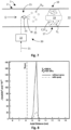
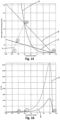
- Fuel cells emit no soot particles. Due to the low concentration of ambient aerosols, only a few droplets can form through heterogeneous nucleation. Instead, most droplets form through homogeneous nucleation during which molecules condensate and form nuclei without the presence of foreign ions or particles. Homogeneous nucleation can occur inside the fuel cell system, e.g., in a turbine or a nozzle, or in the plume during mixing and cooling with ambient air. The occurrence and place of homogeneous nucleation depends on the system architecture, operating conditions and ambient conditions. Homogeneous nucleation leads to a high concentration of small droplet radii, often below one micron. If the droplets freeze to persistent ice crystals, the resulting contrail might have a stronger climate impact than a contrail of a conventional aircraft engine. Therefore, it is important to reduce the contrail formation of fuel cell aircraft as much as possible or avoid it altogether.
- EP 3 961 012 A1 relates to an aircraft flight contrail assessment device comprising a contrail sensor adapted to produce contrails data representative of an atmosphere parameter having an influence on the formation of contrails or an observation parameter varying depending on at least the presence of one or more contrails, and a processing unit adapted to calculate at least a contrails value representative of an amount of contrail, based on said contrails data.
- the invention provides such device as well a corresponding method to evaluate the amount of contrails produced by an aircraft during a flight.
- US 11 579 050 B2 relates to a system, configured for being on board an aircraft.
- the system includes a probe for collecting samples of contrail, a chamber for collecting the samples, a collecting conduit for conducting the samples from the collecting probe the collecting chamber and at least one device for measuring at least one parameter characterizing the samples in the collecting conduit while they are conducted from the collecting probe to the collecting chamber.
- US 5 005 355 A describes a method of suppressing the formation of contrails from the exhaust of an engine operating in cold temperatures including the steps of providing a combined nucleating agent and freeze-point depressant selected from the group of water soluble monohydric, dihydric, trihydric or other polyhydric alcohols, or mixtures thereof, forming the solution into a vapor, and injecting the solution into the exhaust of the engine.
- the solution may include a non-corrosive surfactant.
- Another solution may include an organic or an inorganic nucleating agent, or mixtures thereof, in monohydric, dihydric, or polyhydric alcohols, or mixtures thereof, and in addition may contain one or more surfactants.
- EP 2 150 692 A2 describes an aircraft comprising a gas turbine engine that exhausts a plume of gases in use, the aircraft comprises an ultrasound generator having an ultrasonic actuator and a waveguide to direct ultrasonic waves at the exhaust plume to avoid the formation of contrails.
- EP 2 153 043 A2 describes a method of operating an aircraft, and the aircraft itself, comprising a gas turbine engine that exhausts a plume of gases in use, the aircraft is characterised by comprising an electromagnetic radiation generator and a waveguide to direct electromagnetic radiation at the exhaust plume to avoid the formation of contrails.
- US 7 971 438 B2 deals with the provision of a condensation stage in a heat exchanger arrangement for a gas turbine engine wherein the level of condensation within a final exhaust gas flow from an engine is reduced. Furthermore, by cooling of the exhaust gas flows for mixing with by-pass air flows a water partial pressure at an exhaust gas exit temperature can be provided which is below the eutectic liquid to vapor phase transition and therefore avoid condensation (contrail) formation.
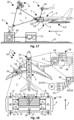
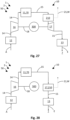
- an energy conversion arrangement for an aircraft comprising a fuel conversion device, in particular a fuel cell system, for converting at least one fuel to electrical and/or mechanical energy; an expansion device arranged in a flow path of exhausts produced in the fuel conversion device and configured to decompress the exhausts; and at least one flow path of air leading to the expansion device for enabling a decompression of the exhausts along with the air.
- an energy system in particular for powering a propulsion unit for propelling an aircraft, comprising a corresponding energy conversion arrangement.
- the energy system may comprise the propulsion unit.
- the energy system may be provided as an engine and/or power plant for an aircraft.
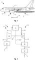
- a fuel cell system of an aircraft two components of a fuel cell system of an aircraft can be mainly considered, namely, the fuel conversion arrangement, e.g., a fuel cell system, and the air supply system.
- the fuel cell system itself converts oxygen and hydrogen to water, which provides electricity, water, and waste heat.
- the air supply provides ambient air including oxygen to the fuel cell and discharges the remaining air including the water.
- the present solution has the advantage that it allows for a reduced humidity output since the humidifier can reduce an amount of water, e.g., water drops, which could form after the fuel conversion in the exhausts. As soon as such waterdrops are released as exhausts to a colder environment, contrails could occur.
- the solution provides a simple way of reducing unwanted contrail impacts, while enabling to support an efficient operation of the energy conversion arrangement.
- the proposed solution provides a reduction of contrail formation for all kinds of aircraft, including but not limited to fuel cell aircraft.
- the proposed solution is lighter, cheaper, uses less space and power and creates no new emissions.
- the proposed solution allows for mitigating a possible disadvantage of fuel cell powered aircrafts by reducing their contribution to contrail production, and thus enhancing their environmental friendliness.
- the energy conversion arrangement further comprises a compressing device for supplying the fuel conversion device with compressed supply air to be used for the fuel conversion.
- the supply air can be used as the air to be decompressed along with the exhausts.
- the compressed supply air can be used for contrail reduction.
- the energy conversion arrangement is configured to extract the air to be led to the expansion device from the compressing device.
- the air compressed in the compressing device may thus fulfil multiple functions. This may provide an efficient and simple way for reducing contrails.
- the compressing device comprises an extraction outlet for extracting the air.
- the extraction outlet can be configured for extracting the air to be decompressed along with the exhausts.
- the extraction outlet may further facilitate providing the air for reducing contrails.
- the extraction outlet is arranged between at least two compression stages of the compressing device.
- the compressing device may have multiple compression stages. Extracting the compressed air through at least one extraction outlet arranged between such compressing stages helps in providing the compressed air with well-defined properties as required and in an efficient manner.
- the energy conversion arrangement further comprises a bypass line and/or duct configured to allow the air to bypass the fuel conversion device on its way from the compressing device to the expansion device.
- Compressed air has to be commonly provided to fuel conversion devices, in particular to fuel cell fuel cell systems.
- a bypass duct for the air to bypass the fuel conversion device helps to avoid an installation of additional systems for providing the air to be decompressed along with the exhausts. This further helps in enabling an efficient way for contrail reduction.
- the energy conversion arrangement is configured to introduce the air into an intermediate section of the expansion device.
- condensation may occur within the expansion device due to a certain humidity of the exhausts expanded therein.
- Introducing the air into an intermediate section of the expansion device can thus help to avoid such a condensation in a highly targeted and efficient manner.
- the expansion device comprises a turbine.
- the expansion device may comprise at least one throttle section.
- the expansion device may comprise a throttle valve.
- a desired rate of decompression of the exhausts may be achieved, possibly without causing any turbulences in the flow of the exhausts or at least less turbulences as may be produced by a turbine. Consequently, the throttle section and/or throttle valve may help in providing decompression while maintaining essentially laminar fluid flows.
- the expansion device may comprise at least one turbine section.
- the expansion device may comprise multiple turbine sections.
- the energy conversion arrangement is configured to gradually replace the exhausts led to the expansion device by the air.
- Gradually replacing the exhausts by air can help to provide any condensation of unity within the exhausts inside of the expansion device and/or helps to reduce contrail formation.
- the replacement further allows for purging the expansion device and any component of the energy conversion arrangement following the flow path of the exhaust thereafter. Consequently, the possibility of providing a gradual replacement of exhausts by the air allows for a highly flexible and adaptable operation of the energy conversion arrangement.
- the energy conversion arrangement is configured to lead the exhausts from the fuel conversion device to a contrail avoidance device.
- the control avoidance device may be provided as and/or comprise a contrail reduction device and/or mixing assembly and may be particularly configured to reduce the formation of contrails and/or to avoid unwanted contrail impacts. Thereby, a highly targeted way for controlling the formation of contrails can be further provided.
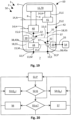
- conversion arrangement further comprises a control unit configured to adjust amount of air led to the expansion device based on at least one measurement value.
- the energy conversion arrangement may further comprise at least one sensor for providing the at least one measurement value representing a temperature value, pressure value and/or humidity value of exhausts and/or the energy conversion arrangement.
- the control unit may be configured to keep the at least one measurement value within a pre-defined value range, and/or above or below a predefined value limit.
- the control unit allows to implement a control mechanism to switch between a contrail reduction mode and the standard operation mode of the energy conversion system. In the majority of flight conditions, no contrail reduction is needed, and the water separation may be omitted or at least reduced to a certain minimum amount. For example, the process of decompressing the exhausts along with air is only conducted, when certain contrail forming conditions are detected.
- energy conversion arrangement further comprises an auxiliary flow path for leading the exhausts from the energy conversion device to an exhaust outlet.
- the energy conversion arrangement may comprise a main flow path and an auxiliary flow path for the exhausts.
- the auxiliary flow path may lead to the contrail avoidance and/or reduction device.
- the auxiliary flow path may be configured as a bypass for bypassing the expansion device.
- the main flow path and the auxiliary flow path may lead to a main exhaust outlet and an auxiliary exhaust outlet, respectively.
- the main flow path and the auxiliary flow path may be combined in order to leave the exhausts to a combined exhaust outlet, for example, involving a mixing assembly of the energy conversion arrangement.
- the energy conversion arrangement, in particular the mixing assembly can be optimised for fully exploiting respective capacities of the main flow path and/or auxiliary flow path.
- This may additionally help to provide an efficient way of expanding the exhausts along with the compressed air and may further help to mix the exhausts with the air and/or further exhausts in a preferably even and complete manner. Thereby, unwanted contrail formation can be further avoided.
- an energy conversion arrangement for an aircraft comprising a fuel conversion device, in particular a fuel cell system, for converting at least one fuel to electrical and/or mechanical energy; an exhaust outlet for letting out exhausts produced in the fuel conversion device by the fuel conversion; and at least one water separator arranged in a flow path of exhausts produced in the fuel conversion device and configured for separating water from products of the fuel conversion device on their way from the fuel conversion device to the exhaust outlet; wherein the at least one water separator comprises permeable membrane and/or absorbent material.
- the water separator can be used.
- the water separator can comprise water separating materials, placed in the exhaust path of the air supply system, to withdraw liquid and gaseous water from the exhaust flow.
- the water withdrawal leads to a reduced humidity of the air supply exhaust flow and hence to a lower risk for contrail formation.
- water can be discharged in the gaseous and/or liquid form.
- the exhausts may pass through the water separator in a cross flow with respect to the separated water.
- the permeable membrane and/or absorbent material can be particularly permeable for water molecules.
- the wherein the at least one water separator is configured to dehumidify the exhausts.
- the content of water vapour in the exhausts may be reduced as they pass the water separator. This can particularly help to reduce the contents of gaseous water in the exhausts and thus the risk of their condensation at a later stage within the energy conversion arrangement and/or after releasing the exhausts into the atmosphere, where they may lead to unwanted contrails.
- the permeable membrane and/or absorbent material at least sectionwise have or has, respectively, molecule size selective properties.
- the molecule size selective properties can allow for a molecular diffusion of water from the water within the separator. Such a molecular diffusion can involve surface diffusion, Knudsen diffusion and/or molecular sieving effects.
- the permeable membrane and/or absorbent material comprises Nafion ® . This allows for a simple construction as well as an efficient operation of the at least one water separator.
- the energy conversion arrangement further comprises a heating device arranged in the flow path of the exhausts after the at least one water separator.
- the heating device provides a heat source between the water separator and the exhaust outlet of the aircraft.
- the heating reduces the saturation, i.e., relative humidity, of the exhaust gas flow.
- a lower saturation reduces or altogether prevents droplet formation and condensation in the exhaust system. Droplet formation might still occur in the plume of the propulsion system. However, a likelihood of the formation of a large number of small droplets is reduced. This decreases the risk of contrail formation, in particular in that water can already have been a withdrawn from the exhausts in the water separator before reaching the heating device.
- the energy conversion arrangement further comprises at least one mixing assembly arranged in the flow path after the water separator and configured to mix the exhausts with further exhausts from the energy conversion arrangement.
- Waste heat of a fuel cell aircraft system can be used in the mixing assembly to avoid a high supersaturation in the plume of the discharged humid exhaust flow of fuel conversion device, e.g., a fuel cell system. This can be achieved by mixing the humid exhaust flow of the air supply system with a warm and dry gas flow before it can mix with the cold ambient air. Thereby, a maximum supersaturation in the plume and hence the number of droplets formed therein may be reduced. A decreased number of droplets reduces an amount of possible ice crystal formation and hence reduces contrail impact.
- a corresponding solution may utilise any heat source for providing the further exhausts.
- a typical air supply system of a fuel conversion device such as a fuel cell
- ambient air is compressed and fed to the fuel conversion device.
- the now humid air is typically expanded in an expansion device, such as a turbine, and then emitted back to the ambient.
- the bypass duct can connect to any duct defining the flow path and/or any kind of source of the exhausts upstream of the expansion device and thus enable relatively humid exhausts from the fuel conversion device, such as air from a fuel cell, to partially, or completely bypass the expansion device, such as a turbine.
- the expansion device such as a turbine
- a certain expansion in the bypass may be inevitable, such that some droplets might form. This is due to the high saturation caused by the low static temperature which is a result of the high flow velocities during expansion. Consequently, the droplets will partly or completely evaporate when the flow is decelerated. However, when the flow of exhausts is decelerated, the static temperature rises again, as the total temperature remains unchanged. This will lead to a partial or complete evaporation of the droplets formed in the bypass. Hence, fewer droplets are emitted, and the contrail contribution of the energy conversion arrangement is reduced. Contrary to that, when being decompressed in the expansion device, for example, a turbine, the droplets might not evaporate, as the expansion device withdraws enthalpy and hence reduces the total temperature of the flow.
- the solution particularly allows for bypassing the expansion device during flight through ISSR where persistent contrails can form.
- no enthalpy is withdrawn from the humid exhaust air and its total temperature remains unchanged.
- the saturation temperature remains unchanged, and therefore, no droplets are formed.
- a main advantage of the solution may thus be seen in allowing to bypass any component of the energy conversion arrangement, which under respective conditions has a strong contrail contribution.
- the emission of fewer or no droplets from the exhaust outlet reduces the contrail impact of the energy conversion system.
- bypassing the expansion device may help to prevent the turbine from stalling or blocking in case of an overload by a certain mass flow and/or volumetric flow of exhausts entering the turbine.
- the bypass duct can thus also be used for regulating the turbine and/or operating it in a desired operating range.
- the bypass duct may additionally help to prevent unwanted condensation of water vapour contained in the exhausts within the turbine. This particularly is the case, if any means, such as a heating device and/or heat exchange device arranged upstream of the expansion device is not present, not enabled or does not provide an amount of heat to the exhausts sufficient for avoiding the condensation.
- the bypass duct connects to the flow path via a junction.
- the water separator can be arranged in the bypass duct.
- the flow junction can divert the exhausts to the water separator.
- the junction may be located and shaped such that it enables to advantageously branch off and/or completely guide the exhausts such that they are led through the bypass duct. Thereby, the junction helps in improving operation and flexibility of the energy conversion arrangement.
- the junction comprises at least one switch valve for switching the flow path from the fuel conversion device to the expansion device and/or the exhaust outlet.
- the switch valve may be located, shaped, and/or operated such that it enables to advantageously branch off and/or completely guide the exhausts such that they are led through the bypass duct. Thereby, the switch valve helps in further improving operation and flexibility of the energy conversion arrangement.
- the switch valve allows for gradual switching of the flow path. Thereby, an amount of exhausts passing through the bypass duct and/or the expansion device can be regulated and/or adjusted as required. This helps in further improving operation and flexibility of the energy conversion arrangement.
- the switch valve allows for a steplessly variable switching of the flow path.
- an amount of exhausts passing through the bypass duct and/or the expansion device can be finely regulated and/or adjusted according to respective requirements. This helps in further improving controllability and flexibility of the energy conversion arrangement.
- the energy conversion arrangement further comprises a control unit configured to monitor at least one contrail formation parameter having a contrail formation range indicating a likelihood of contrail formation by exhausts of the fuel conversion device and/or by an exhausts mix containing the exhausts of the fuel conversion device and further exhausts of the energy conversion arrangement, and to control a drying ratio of the exhausts by the at least one water separator to keep and/or bring the at least one contrail formation parameter out of at least one potential impact region of the contrail formation range indicative of a potential contrail impact to be avoided and/or reduced.
- a potential contrail impact can be avoided by avoiding or at least reducing contrails.
- the control unit allows to implement a control mechanism to switch between a contrail reduction mode and the standard operation mode of the energy conversion system. In the majority of flight conditions, no contrail reduction is needed, and the water separation may be omitted or at least reduced to a certain minimum amount. For example, water separation is only conducted, when certain contrail forming conditions are detected.
- a contrail reduction device is configured to introduce droplets of water into the flow path, such that smaller droplets in the exhausts are collected through droplet coagulation.
- the contrail reduction device can be arranged upstream of the at least one water separator.
- the at least one water separator can have at least one exhaust inlet, at least one dry outlet, and at least one wet outlet.
- the contrail reduction device can be arranged in fluid connection with the exhaust flow and configured to introduce droplets of water into the exhaust flow. Thereby, droplets sprayed into the flow hinder nucleation due to their own growth through condensation and the related latent heat release. This reduces the supersaturation and hence the homogeneous nucleation.
- introducing large droplets can still be beneficial.
- the droplets then provide a phase boundary for condensation in the plume. This will reduce or at least suppress homogeneous nucleation in the plume, thus also helping to reduce contrail production and enhance natural dissipation of contrails.
- the water introduced by the contrail reduction device is at least partly provided by the water separation device.
- water withdrawn from the exhausts by means of the water separator can be reintroduced into the exhausts by the contrail reduction device.
- the water separator or water separation device can thus help in enhancing synergetic effects of the contrail reduction device.
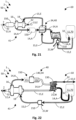
- a an energy conversion arrangement for an aircraft comprising a fuel conversion device, in particular a fuel cell system, for converting at least one fuel to electrical and/or mechanical energy; a flow path of the supply air leading from an air inlet for taking up the air from ambient surroundings, such as the atmosphere, and/or from inside a hull, e.g., from a cabin of the aircraft, to the fuel conversion device for converting the fuel, a flow path of exhausts leading from the fuel conversion device to an exhaust outlet for letting out the exhausts produced in the fuel conversion device by the fuel conversion; and a humidifying device arranged in the flow paths and configured to humidify the supply air with water from the exhausts.
- a fuel conversion device in particular a fuel cell system, for converting at least one fuel to electrical and/or mechanical energy
- a flow path of the supply air leading from an air inlet for taking up the air from ambient surroundings, such as the atmosphere, and/or from inside a hull, e.g., from a cabin of the aircraft, to the fuel conversion device for
- the humidifier can be used for humidification of the supply air which can be provided to a cathode side of fuel cells of the fuel cell system or could at least support such an air supply with humid air which may improve an efficiency and/or operation of the energy conversion arrangement, in particular of the fuel cell system.
- discharged water can be used in the gaseous and/or liquid form. The exhausts may pass through the humidifier in a cross flow with respect to the supply air.
- the humidifying device can make use of a relatively high humidity of the exhausts after leaving the turbine to humidify the supply air and therefore the fuel conversion device, in particular the fuel cell system.
- the relative humidity of the exhausts exiting the expansion device is commonly higher than the relative humidity of the exhausts entering the expansion device.
- arranging the humidification device after the expansion device allows for enhancing dehumidification of the exhausts and/or humidification of the supply air.
- the air supply system comprises a compressing device for supplying the fuel conversion device with compressed inlet air to be used for the fuel conversion; and at least one heat exchange unit configured to extract heat from the compressing device and/or the compressed air to be used for the conversion.
- the compressing device and/or compressed air may be cooled by means of the heat exchange unit.
- the heat exchange may help to improve overall energetic efficiency of the energy conversion arrangement, while at the same time contributing to contrail reduction.
- the at least one heat exchange unit is configured to heat up the exhausts. Heating up the exhausts may help in reducing a relative humidity of the exhausts. The reduced relative humidity may decrease the amount of contrails produced and may facilitate dissipation of any remaining contrails.
- the energy conversion arrangement further comprises at least one particle filter element and/or at least one chemical filter element arranged in the flow path of the supply air before and/or after the at least one heat exchange unit, respectively.
- the at least one particle filter element may help to remove unwanted particles and/or contamination from the supply air. This may help to further improve operation of the humidifying device and/or the energy conversion device.
- the air supply system is configured to be at least partly cooled by exhausts from the humidifying device. Exhausts from the turbine (which can be cooled down afterwards) may be used to cool down the supply air coming from a compressor/filter.
- the heat exchange unit may thus function as an air (exhausts) / air intercooler. This may help to further improve an efficient operation of the energy conversion arrangement.
- energy conversion arrangement further comprises at least one water separator arranged in a flow path of exhausts produced in the fuel conversion device and configured for separating water from products of the fuel conversion device on their way from the fuel conversion device to the exhaust outlet.
- the water separator may help to initially remove water from the exhausts when they have a particularly high relative humidity. Water separated from the exhausts may be discharged and/or used to supply the contrail reduction device of the energy conversion arrangement. Thereby, the water separator helps to avoid unwanted contrail impacts.
- the at least one water separator is arranged between the fuel conversion device and the humidifying device.
- Such an arrangement of the water separator may particularly help to remove surplus water from the exhausts which may not be efficiently used and/or be necessary for the humidification process. This may help to further improve an efficient operation of the energy conversion arrangement.
- the at least one water separator comprises a permeable membrane and/or absorbent material.
- the permeable membrane and/or absorbent material can be particularly permeable for water molecules. This allows for a simple construction as well as an efficient operation and of the at least one water separator.
- the energy conversion arrangement further comprises a control unit configured to adjust a humidity of the supply air based on at least one measurement value to provide humidity control for the fuel conversion device.
- a control mechanism configured to switch between a contrail reduction mode and a standard operation mode of the energy conversion system, and/or to adjust a humidification of the supply air according to certain operational requirements of the fuel conversion device. This may help to further improve operation of the humidifying device and/or the energy conversion device, while at the same time allowing for selectively avoiding unwanted contrail impacts.
- a method for controlling an energy conversion arrangement for an aircraft comprising a fuel conversion device with a fuel cell system for converting at least one fuel to electrical energy, the method comprising the steps of monitoring at least one contrail formation parameter having a contrail formation range indicating a likelihood of contrail formation by exhausts of the fuel conversion device and/or by an exhausts mix containing the exhausts of the fuel conversion device and further exhausts of the energy conversion arrangement; and controlling a mixing ratio of the exhausts of the fuel conversion device with the further exhausts of the energy conversion arrangement to keep and/or bring the at least one contrail formation parameter out of at least one potential impact region of the contrail formation range indicative of a potential contrail impact to be avoided.
- a control program for controlling an energy conversion arrangement of an aircraft comprising a fuel conversion device with a fuel cell system for converting at least one fuel to electrical energy, wherein the control program comprises instructions which, when the control program is executed by a control device, cause the control device to carry out a responding method.
- a computer-readable data carrier having stored thereon a corresponding control program is provided.
- a control device for controlling an energy conversion arrangement of an aircraft comprising a fuel conversion device with a fuel cell system for converting at least one fuel to electrical energy, wherein the control device is configured to carry out a corresponding method and/or comprises a corresponding computer-readable data carrier.
- an aircraft comprising a corresponding energy conversion arrangement.
- the exhausts of the fuel conversion device are being admixed to the further exhausts of the of the energy conversion arrangement and/or in a second impact region of the contrail formation range indicative of a second potential contrail impact, the further exhausts of the of the energy conversion arrangement are being admixed to the exhausts of the fuel conversion device.
- the ASP outflow can be fully mixed with the TMS outflow
- a controlled amount of the TMS outflow can be added to the ASP outflow to optimize the properties of the cooling contrail.
- a remaining TMS outflow can be emitted separately. This further helps to avoid energy losses due to the mixing process in that the mixing process is specifically tailored to respective flight conditions.
- the contrail formation parameter comprises an exhaust temperature value, an exhaust pressure value and/or an exhaust humidity value of the exhausts, the further exhausts, and/or the exhausts mix, and/or an atmospheric temperature value, an atmospheric pressure value, an atmospheric humidity value, and/or atmospheric aerosol value of the atmosphere surrounding the aircraft.
- Any extrinsic and/or intrinsic physical and/or chemical property value of the exhausts, the further exhausts, the exhausts mix can be acquired, for example, before, during and/or after mixing the exhausts.
- An atmospheric concentration of aerosols can be indicative of respective particles and/or droplets contained in the atmosphere which may serve as nuclei for droplet and/or ice crystal formation. This further enhances the possibilities of allowing for a controlled application of the solution which further helps to apply contrail reduction manners in a flexible and adaptive manner.
- the contrail formation parameter comprises a plume condition value indicating at least one aspect of a physical and/or chemical condition of a plume of the exhausts and/or the exhausts mix behind the aircraft.
- the plume condition value may be detected by visual and/or radar detection means and may be detected from the aircraft, a satellite, a ground station and/or from another aircraft.
- the plume condition value may comprise at least one parameter value indicative of a temperature, pressure, humidity and/or composition of the plume, including of potential ice crystals contained therein. This further enhances the possibilities of allowing for a controlled application of the solution which further helps to apply contrail reduction manners in a flexible and adaptive manner.
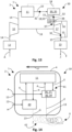
- the energy conversion arrangement further comprises a mixing assembly with at least one first control valve configured for admixing the exhausts of the fuel conversion device to the further exhausts of the of the energy conversion arrangement and/or with at least one second control valve configured for admixing the further exhausts of the of the energy conversion arrangement to the exhausts of the fuel conversion device.
- the control valves may be provided in the form of throttle devices configured to throttle a flow of the exhausts and/or the further exhausts, respectively, entering the mixing assembly.
- the at least one first control valve is arranged in a flow path of the exhausts of the fuel conversion device downstream of an air supply system of the energy conversion arrangement and/or the at least one second control valve is arranged in a flow path of the further exhausts downstream of as thermal management system of the energy conversion arrangement.
- the air supply system (ASP) may provide air to the fuel conversion arrangement.
- the thermal management system (TMS) may help to regulate a temperature of the fuel conversion arrangement.
- a method for controlling an energy conversion arrangement for an aircraft comprising a fuel conversion device with a fuel cell system having at least two fuel cell elements for converting at least one fuel to electrical energy, the method comprising the steps of monitoring at least one contrail formation parameter having a contrail formation range indicating a likelihood of contrail formation by exhausts of the fuel conversion device and/or by an exhausts mix containing the exhausts of the fuel conversion device and further exhausts of the energy conversion arrangement; and controlling the fuel cell system such the at least two fuel cell elements are being operated each at a different current density to keep and/or bring the at least one contrail formation parameter out of at least one potential impact region of the contrail formation range indicative of a potential contrail impact to be avoided.
- the fuel cell system may comprise and/or may be comprised of at least one fuel cell unit containing multiple fuel cell elements which may be a single fuel cell that can constitute a respective smallest controllable element of the fuel cell unit.
- the aircraft may comprise multiple fuel cell units which may be used for generating electrical energy for propulsion of the aircraft and/or for powering auxiliary systems of the aircraft, such as an auxiliary power unit (APUs).
- APUs auxiliary power unit
- a deliberate efficiency reduction can be realized by operating fuel cell elements at different power densities. This can be achieved by operating some fuel cell driven propulsion units and/or engines at a higher power level and others which can thus be operated at a relatively low power level. Another option is to operate one or more fuel cell elements, e.g., stacks, within a fuel cell engine at a higher power density than the others. As a result, some stacks will provide little power at a high efficiency while others provide much power at a lower efficiency. Overall, the efficiency is lower than at an equal power density, the hydrogen consumption is higher, but the overall power provided to the aircraft can remain constant.
- the proposed solution thus allows for an intentional degradation of the efficiency of the fuel cell reaction and can be applied to produce more heat in order to have an exhaust flow with a lower relative humidity, considering that a fuel cell usually has a lower efficiency at higher power densities. Consequently, a combined exhaust flow and/or exhausts mix can be warmer and much drier than the exhaust flow from the air supply system for themselves. This strongly reduces the risk for droplet condensation in the engine plume and hence reduces the risk of undesired contrail formation.
- Contrails may have numerous different impacts including larger or smaller climate impacts, depending on ice crystal density, shape etc. Hence, even if a formation of contrails cannot be completely avoided, at least certain unwanted impacts, such as negative climate impacts of the contrails, can be avoided or at least reduced. Respective controlled contrail reduction measures should thus be applied only during flight through a region with the risk for contrail formation.
- the at least two fuel cell elements are associated to respective different fuel cell stacks of the fuel cell system.
- a stack-wise imbalance may be used to operate the at least two fuel cell elements at a different current density.
- Such an imbalance may be a simple way to provide increased heat output for keeping and/or bringing at least one contrail formation parameter out of at least one potential impact region of the contrail formation range indicate of a potential contrail region to be avoided.
- At least one of the at least two fuel cell elements is operated at a different fuel conversion rate as the other at least one of the at least two fuel cell elements.
- the different current densities of the at least two fuel cell elements may be achieved by the different fuel conversion rates.
- the resulting imbalance in the fuel conversion rate of the at least two fuel cell elements may again be a simple way to provide increased heat output for keeping and/or bringing at least one contrail formation parameter out of at least one potential impact region of the contrail formation range indicate of a potential contrail region to be avoided.
- At least one of the at least two fuel cell elements is operated at a different power density as the other at least one of the at least two fuel cell elements.
- two fuel cell elements of the same fuel cell unit may be operated at different power density.
- a waste heat ratio of the fuel cell system is at least temporarily being increased to bring the at least one contrail formation parameter out of the contrail formation range.
- the waste heat ratio may be increased by operating the at least two fuel cell elements at a different current density.
- a thermal management system may be controlled in a manner that the waste heat ratio is at least temporarily increased. This may further help to reduce a relative humidity of the exhausts and thus the risk of contrail formation.
- a relative humidity of the exhausts is being at least temporarily reduced.
- a temporary reduction of relative humidity for a selected flight region may be achieved by a targeted application of the proposed solution, adjusting the energy output of the fuel cell system such that its energy output can be increased for at least a part of a selected flight path to keep and/or bring the at least one contrail formation parameter out of at least one potential impact region of the contrail formation range indicative of a potential contrail impact to be avoided.
- the thermal management system is configured to take in cooling air, heat up the cooling air, and discharge the heated-up cooling air as the further exhausts. Otherwise, the cooling air would probably have to be injected from the aircraft anyway. Consequently, using the cooling air for at least partly providing the further exhausts provides synergetic effects when applying the further exhausts for contrail reduction.
- the thermal management system is configured to take in the cooling air from ambient surroundings. If taken up from ambient surroundings, in particular at cruising altitudes of aircrafts, the cooling air may be particularly cold and dry. Hence, heating up the cooling air by means of the thermal management system even further adds to the relative dryness of the cooling air. Thus, mixing the relatively dry cooling air with the exhausts can help in reducing humidity of the overall exhausts of the aircraft, which may be beneficial for reducing contrails.
- the thermal management system is configured to provide the fuel conversion device with a coolant at a coolant inlet temperature, and to receive back from the fuel conversion device the coolant at a coolant outlet temperature, wherein the coolant inlet temperature is lower than the coolant outlet temperature at least when the fuel conversion device operates at an operating temperature.
- the coolant thus helps in regulating the temperature of the fuel conversion device. Consequently, the coolant may contribute to enhancing and overall energetic efficiency of the energy conversion arrangement, while at the same time reducing contrail production.
- the energy conversion arrangement further comprises an air supply system for supplying the fuel conversion device with supply air for the fuel conversion arranged upstream of the exhaust outlet. Consequently, the exhausts may at least partly flow through the air supply system. Consequently, the air supply system may be used to heat up the exhausts. This may help in reducing contrail production in that a relative humidity of the exhausts is being reduced.
- the air supply system comprises a compressing device for supplying the fuel conversion device with compressed inlet air to be used for the fuel conversion; and at least one heat exchange unit configured to extract heat from the compressing device and/or the compressed air to be used for the conversion.
- the compressing device and/or compressed air may be cooled by means of the heat exchange unit.
- the heat exchange may help to improve overall energetic efficiency of the energy conversion arrangement, while at the same time contributing to contrail reduction.
- the at least one heat exchange unit is configured to heat up the exhausts. Heating up the exhausts may help in reducing a relative humidity of the exhausts. The reduced relative humidity may decrease the amount of contrails produced and may facilitate dissipation of any remaining contrails.
- the energy conversion arrangement further comprises an expansion device for decompressing the exhausts arranged in the flow path of the exhausts upstream of the mixing assembly.
- the expansion device may be configured to generate electrical and/or mechanical energy by expanding the exhausts.
- the expansion device may comprise at least one turbine.
- the expansion device may be part of the air supply system. Consequently, the expansion device may help to improve overall energetic efficiency of the energy conversion arrangement.
- the further exhausts provide a gas flow that is relatively drier than the exhausts.
- mixing the further last with the exhausts can help in reducing humidity of the overall exhausts of the aircraft, which may be beneficial for reducing contrails.
- the mixing operation may be applied whenever necessary in order to achieve a desired amount of contrail reduction. Consequently, the mixing operation helps in providing a versatile store of measures for contrail reduction.
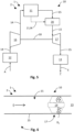
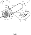
- the mixing assembly comprises a further exhaust outlet opening configured to let out the further exhausts to ambient surroundings; wherein the exhaust outlet has an exhaust outlet opening configured to let out the exhausts to the ambient surroundings; and wherein the further exhaust outlet is arranged before the exhaust outlet with respect to an intended direction of movement of the aircraft during standard operation of the aircraft along a discharge line extending essentially in parallel to the direction of movement.
- the further exhaust outlet opening can be arranged before the exhaust outlet opening such that warm and dry further exhaust air is mixed with humid air exhausts from the fuel conversion device during operation of the aircraft. Mixing the further exhausts with the exhausts in such a way may help in additionally reducing a relative humidity of the overall exhausts of the aircraft. The reduced relative humidity may decrease the amount of contrails produced and may facilitate dissipation of any remaining contrails.
- the energy conversion arrangement further comprises an air inlet, wherein the air inlet is in fluid connection with ambient air and/or cabin air of the aircraft.
- Ambient air and/or cabin air can be fed to the energy conversion arrangement, in particular the fuel conversion device.
- ambient air can be rather dry and cold
- cabin air can rather be warm and dry in comparison to the ambient air
- fuel conversion can help in optimising conversion temperatures in the fuel conversion device and thereby contribute to the reduction of contrails.
Landscapes
- Engineering & Computer Science (AREA)
- Chemical & Material Sciences (AREA)
- Aviation & Aerospace Engineering (AREA)
- Chemical Kinetics & Catalysis (AREA)
- Sustainable Energy (AREA)
- Sustainable Development (AREA)
- Life Sciences & Earth Sciences (AREA)
- Electrochemistry (AREA)
- General Chemical & Material Sciences (AREA)
- Manufacturing & Machinery (AREA)
- Combustion & Propulsion (AREA)
- Mechanical Engineering (AREA)
- Fuel Cell (AREA)
Priority Applications (3)
| Application Number | Priority Date | Filing Date | Title |
|---|---|---|---|
| US18/987,856 US20250206154A1 (en) | 2023-12-21 | 2024-12-19 | Energy conversion arrangement, energy system and aircraft comprising same |
| US18/987,902 US20250207538A1 (en) | 2023-12-21 | 2024-12-19 | Energy conversion arrangement, energy system and aircraft comprising same |
| US18/987,714 US20250206153A1 (en) | 2023-12-21 | 2024-12-19 | Energy conversion arrangement, energy system and aircraft comprising same |
Applications Claiming Priority (5)
| Application Number | Priority Date | Filing Date | Title |
|---|---|---|---|
| EP23290050.6A EP4574660A1 (de) | 2023-12-21 | 2023-12-21 | Energieumwandlungsanordnung, energiesystem und flugzeug damit |
| EP23290052.2A EP4574672A1 (de) | 2023-12-21 | 2023-12-21 | Energieumwandlungsanordnung, energiesystem und flugzeug damit |
| EP23290049.8A EP4574670A1 (de) | 2023-12-21 | 2023-12-21 | Energieumwandlungsanordnung, energiesystem und flugzeug damit |
| EP23290048.0A EP4574678A1 (de) | 2023-12-21 | 2023-12-21 | Energieumwandlungsanordnung und flugzeug damit |
| EP23290051.4A EP4574671A1 (de) | 2023-12-21 | 2023-12-21 | Energieumwandlungsanordnung, energiesystem und flugzeug damit |
Publications (1)
| Publication Number | Publication Date |
|---|---|
| EP4574673A1 true EP4574673A1 (de) | 2025-06-25 |
Family
ID=92633736
Family Applications (4)
| Application Number | Title | Priority Date | Filing Date |
|---|---|---|---|
| EP24290026.4A Pending EP4574666A1 (de) | 2023-12-21 | 2024-08-07 | Verfahren, steuerprogramm, computerlesbarer datenträger und steuereinrichtung zum steuern einer energieumwandlungsanordnung sowie flugzeug damit |
| EP24290029.8A Pending EP4574668A1 (de) | 2023-12-21 | 2024-08-07 | Verfahren, steuerprogramm, computerlesbarer datenträger und steuereinrichtung zum steuern einer energieumwandlungsanordnung sowie flugzeug damit |
| EP24290028.0A Pending EP4574673A1 (de) | 2023-12-21 | 2024-08-07 | Energieumwandlungsanordnung, energiesystem und flugzeug damit |
| EP24290027.2A Pending EP4574667A1 (de) | 2023-12-21 | 2024-08-07 | Verfahren, steuerprogramm, computerlesbarer datenträger und steuereinrichtung zum steuern einer energieumwandlungsanordnung sowie flugzeug damit |
Family Applications Before (2)
| Application Number | Title | Priority Date | Filing Date |
|---|---|---|---|
| EP24290026.4A Pending EP4574666A1 (de) | 2023-12-21 | 2024-08-07 | Verfahren, steuerprogramm, computerlesbarer datenträger und steuereinrichtung zum steuern einer energieumwandlungsanordnung sowie flugzeug damit |
| EP24290029.8A Pending EP4574668A1 (de) | 2023-12-21 | 2024-08-07 | Verfahren, steuerprogramm, computerlesbarer datenträger und steuereinrichtung zum steuern einer energieumwandlungsanordnung sowie flugzeug damit |
Family Applications After (1)
| Application Number | Title | Priority Date | Filing Date |
|---|---|---|---|
| EP24290027.2A Pending EP4574667A1 (de) | 2023-12-21 | 2024-08-07 | Verfahren, steuerprogramm, computerlesbarer datenträger und steuereinrichtung zum steuern einer energieumwandlungsanordnung sowie flugzeug damit |
Country Status (2)
| Country | Link |
|---|---|
| EP (4) | EP4574666A1 (de) |
| DE (5) | DE102024122542A1 (de) |
Citations (10)
| Publication number | Priority date | Publication date | Assignee | Title |
|---|---|---|---|---|
| US5005355A (en) | 1988-08-24 | 1991-04-09 | Scipar, Inc. | Method of suppressing formation of contrails and solution therefor |
| EP2150692A2 (de) | 2007-05-26 | 2010-02-10 | Rolls-Royce plc | Verfahren und vorrichtung zur unterdrückung von flugzeugtriebwerkkondensstreifen |
| EP2153043A2 (de) | 2007-05-26 | 2010-02-17 | Rolls-Royce plc | Verfahren und vorrichtung zur unterdrückung von flugtriebwerk-kondensstreifen |
| US7971438B2 (en) | 2006-05-05 | 2011-07-05 | Rolls-Royce Plc | Gas turbine engine having a heat exchanger arrangement for exhaust gas flows |
| EP3961012A1 (de) | 2020-09-01 | 2022-03-02 | Airbus Operations, S.L.U. | Vorrichtung und verfahren zur beurteilung von flugzeugflugkondensstreifen |
| US20220332219A1 (en) * | 2021-03-31 | 2022-10-20 | ZeroAvia, Ltd. | Exhaust water vapor management for hydrogen fuel cell-powered aircraft |
| US11579050B2 (en) | 2020-03-11 | 2023-02-14 | Airbus Sas | System for sampling and analyzing contrails generated by an aircraft |
| US11643220B2 (en) * | 2019-07-12 | 2023-05-09 | Airbus Sas | Electricity production system for an aircraft, comprising a fuel cell |
| US11876263B1 (en) * | 2023-01-31 | 2024-01-16 | ZeroAvia, Inc. | Cathode ejector cooling flow control system |
| US20240186541A1 (en) * | 2022-12-06 | 2024-06-06 | Airbus Operations Sas | Method and sysem for humidifying an air supply of a fuel cell for aircraft |
Family Cites Families (5)
| Publication number | Priority date | Publication date | Assignee | Title |
|---|---|---|---|---|
| WO2022040054A1 (en) * | 2020-08-21 | 2022-02-24 | Universal Hydrogen Co. | Systems and methods for multi-module control of a hydrogen powered hybrid electric powertrain |
| WO2022232828A1 (en) * | 2021-04-30 | 2022-11-03 | University Of Florida Research Foundation, Inc. | Semi-closed cycle aero engine with contrail suppression |
| DE102021004031A1 (de) * | 2021-08-03 | 2023-02-09 | Hans-Martin Striebel | Langstrecken - Verkehrsflugzeug ohne schädliche Emissionen, genannt Care - Liner |
| GB202114829D0 (en) * | 2021-10-18 | 2021-12-01 | Rolls Royce Plc | Aircraft propulsion system |
| US12347896B2 (en) * | 2022-06-10 | 2025-07-01 | Zeroavia Ltd | Pumped two-phase fuel cell cooling |
-
2024
- 2024-08-07 DE DE102024122542.4A patent/DE102024122542A1/de active Pending
- 2024-08-07 EP EP24290026.4A patent/EP4574666A1/de active Pending
- 2024-08-07 EP EP24290029.8A patent/EP4574668A1/de active Pending
- 2024-08-07 EP EP24290028.0A patent/EP4574673A1/de active Pending
- 2024-08-07 EP EP24290027.2A patent/EP4574667A1/de active Pending
- 2024-08-07 DE DE102024122544.0A patent/DE102024122544A1/de active Pending
- 2024-08-07 DE DE102024122543.2A patent/DE102024122543A1/de active Pending
- 2024-08-07 DE DE102024122546.7A patent/DE102024122546A1/de active Pending
- 2024-08-07 DE DE102024122550.5A patent/DE102024122550A1/de active Pending
Patent Citations (10)
| Publication number | Priority date | Publication date | Assignee | Title |
|---|---|---|---|---|
| US5005355A (en) | 1988-08-24 | 1991-04-09 | Scipar, Inc. | Method of suppressing formation of contrails and solution therefor |
| US7971438B2 (en) | 2006-05-05 | 2011-07-05 | Rolls-Royce Plc | Gas turbine engine having a heat exchanger arrangement for exhaust gas flows |
| EP2150692A2 (de) | 2007-05-26 | 2010-02-10 | Rolls-Royce plc | Verfahren und vorrichtung zur unterdrückung von flugzeugtriebwerkkondensstreifen |
| EP2153043A2 (de) | 2007-05-26 | 2010-02-17 | Rolls-Royce plc | Verfahren und vorrichtung zur unterdrückung von flugtriebwerk-kondensstreifen |
| US11643220B2 (en) * | 2019-07-12 | 2023-05-09 | Airbus Sas | Electricity production system for an aircraft, comprising a fuel cell |
| US11579050B2 (en) | 2020-03-11 | 2023-02-14 | Airbus Sas | System for sampling and analyzing contrails generated by an aircraft |
| EP3961012A1 (de) | 2020-09-01 | 2022-03-02 | Airbus Operations, S.L.U. | Vorrichtung und verfahren zur beurteilung von flugzeugflugkondensstreifen |
| US20220332219A1 (en) * | 2021-03-31 | 2022-10-20 | ZeroAvia, Ltd. | Exhaust water vapor management for hydrogen fuel cell-powered aircraft |
| US20240186541A1 (en) * | 2022-12-06 | 2024-06-06 | Airbus Operations Sas | Method and sysem for humidifying an air supply of a fuel cell for aircraft |
| US11876263B1 (en) * | 2023-01-31 | 2024-01-16 | ZeroAvia, Inc. | Cathode ejector cooling flow control system |
Non-Patent Citations (3)
| Title |
|---|
| ANONYMOUS: "Turbofan - Wikipedia", 13 December 2023 (2023-12-13), XP093238665, Retrieved from the Internet <URL:https://web.archive.org/web/20231213114010/https://en.wikipedia.org/wiki/Turbofan> * |
| H. CRUZ CHAMPIONS. KABELAC: "Multifunctional fuel cell system for civil aircraft: Study of the cathode exhaust gas dehumidification", INTERNATIONAL JOURNAL OF HYDROGEN ENERGY, vol. 42, 2017, pages 29518 - 29531, XP085249062, DOI: 10.1016/j.ijhydene.2017.09.175 |
| TEYMOURTASH ET AL.: "The effects of rate of expansion and injection of water droplets on the entropy generation of nucleating steam flow in a Laval nozzle", HEAT MASS TRANSFER, vol. 45, 2009, pages 1185 - 1198, XP019704148 |
Also Published As
| Publication number | Publication date |
|---|---|
| EP4574666A1 (de) | 2025-06-25 |
| EP4574667A1 (de) | 2025-06-25 |
| DE102024122543A1 (de) | 2025-06-26 |
| DE102024122546A1 (de) | 2025-06-26 |
| DE102024122550A1 (de) | 2025-06-26 |
| DE102024122542A1 (de) | 2025-06-26 |
| EP4574668A1 (de) | 2025-06-25 |
| DE102024122544A1 (de) | 2025-06-26 |
Similar Documents
| Publication | Publication Date | Title |
|---|---|---|
| CN107428415B (zh) | 具有冗余的有效引气系统的飞行器 | |
| US9614238B2 (en) | Fuel cell system | |
| US20060029849A1 (en) | System for water reclamation from an exhaust gas flow of a fuel cell of an aircraft | |
| CN104903193B (zh) | 用于航空器的空气调节方法和系统 | |
| EP4509398A1 (de) | Wärmeverwaltungssystem für ein brennstoffzellenflugzeug | |
| EP4512721A1 (de) | Flüssigwasserstoffzufuhrsystem für brennstoffzellenbetriebenes flugzeug | |
| EP4509409A1 (de) | Integration eines gondelluftwärmetauschers für ein mit wasserstoffbetriebener brennstoffzelle angetriebenes flugzeug | |
| CN119451892A (zh) | 飞机推进系统和方法 | |
| EP4574660A1 (de) | Energieumwandlungsanordnung, energiesystem und flugzeug damit | |
| EP4574673A1 (de) | Energieumwandlungsanordnung, energiesystem und flugzeug damit | |
| EP4574662A1 (de) | Energieumwandlungsanordnung, energiesystem und flugzeug damit | |
| EP4574671A1 (de) | Energieumwandlungsanordnung, energiesystem und flugzeug damit | |
| EP4574672A1 (de) | Energieumwandlungsanordnung, energiesystem und flugzeug damit | |
| EP4574670A1 (de) | Energieumwandlungsanordnung, energiesystem und flugzeug damit | |
| EP4574678A1 (de) | Energieumwandlungsanordnung und flugzeug damit | |
| EP4510250A2 (de) | Niedertemperatur-protonenaustauschmembran-ladeluftwärmetauscher | |
| CN115621499A (zh) | 用于燃料电池系统的基于水的、组合的冷却和加湿系统 | |
| EP4574661A1 (de) | Energieumwandlungsanordnung, energiesystem und flugzeug damit | |
| US20250207538A1 (en) | Energy conversion arrangement, energy system and aircraft comprising same | |
| US20250206153A1 (en) | Energy conversion arrangement, energy system and aircraft comprising same | |
| US20250206154A1 (en) | Energy conversion arrangement, energy system and aircraft comprising same | |
| EP4691913A1 (de) | Energieumwandlungsanordnung, energiesystem und flugzeug damit | |
| EP4574663A1 (de) | Energieumwandlungsanordnung, energiesystem und flugzeug damit | |
| EP4509410A1 (de) | Gepumpte zweiphasenkühlung von flugzeugelektronik | |
| EP4510251A2 (de) | Start eines hochtemperatur-protonenaustauschmembran (htpem)-brennstoffzellenflugzeugs mit mehreren stromerzeugungseinheiten |
Legal Events
| Date | Code | Title | Description |
|---|---|---|---|
| PUAI | Public reference made under article 153(3) epc to a published international application that has entered the european phase |
Free format text: ORIGINAL CODE: 0009012 |
|
| STAA | Information on the status of an ep patent application or granted ep patent |
Free format text: STATUS: THE APPLICATION HAS BEEN PUBLISHED |
|
| AK | Designated contracting states |
Kind code of ref document: A1 Designated state(s): AL AT BE BG CH CY CZ DE DK EE ES FI FR GB GR HR HU IE IS IT LI LT LU LV MC ME MK MT NL NO PL PT RO RS SE SI SK SM TR |
|
| STAA | Information on the status of an ep patent application or granted ep patent |
Free format text: STATUS: REQUEST FOR EXAMINATION WAS MADE |
|
| 17P | Request for examination filed |
Effective date: 20251218 |