EP4574530A1 - Fahrzeugsteuerungsvorrichtung und fahrzeugsteuerungsverfahren - Google Patents
Fahrzeugsteuerungsvorrichtung und fahrzeugsteuerungsverfahren Download PDFInfo
- Publication number
- EP4574530A1 EP4574530A1 EP23854744.2A EP23854744A EP4574530A1 EP 4574530 A1 EP4574530 A1 EP 4574530A1 EP 23854744 A EP23854744 A EP 23854744A EP 4574530 A1 EP4574530 A1 EP 4574530A1
- Authority
- EP
- European Patent Office
- Prior art keywords
- difference
- sum
- vehicle
- torque
- model
- Prior art date
- Legal status (The legal status is an assumption and is not a legal conclusion. Google has not performed a legal analysis and makes no representation as to the accuracy of the status listed.)
- Pending
Links
Images




Classifications
-
- B—PERFORMING OPERATIONS; TRANSPORTING
- B60—VEHICLES IN GENERAL
- B60W—CONJOINT CONTROL OF VEHICLE SUB-UNITS OF DIFFERENT TYPE OR DIFFERENT FUNCTION; CONTROL SYSTEMS SPECIALLY ADAPTED FOR HYBRID VEHICLES; ROAD VEHICLE DRIVE CONTROL SYSTEMS FOR PURPOSES NOT RELATED TO THE CONTROL OF A PARTICULAR SUB-UNIT
- B60W10/00—Conjoint control of vehicle sub-units of different type or different function
- B60W10/12—Conjoint control of vehicle sub-units of different type or different function including control of differentials
- B60W10/16—Axle differentials, e.g. for dividing torque between left and right wheels
-
- B—PERFORMING OPERATIONS; TRANSPORTING
- B60—VEHICLES IN GENERAL
- B60L—PROPULSION OF ELECTRICALLY-PROPELLED VEHICLES; SUPPLYING ELECTRIC POWER FOR AUXILIARY EQUIPMENT OF ELECTRICALLY-PROPELLED VEHICLES; ELECTRODYNAMIC BRAKE SYSTEMS FOR VEHICLES IN GENERAL; MAGNETIC SUSPENSION OR LEVITATION FOR VEHICLES; MONITORING OPERATING VARIABLES OF ELECTRICALLY-PROPELLED VEHICLES; ELECTRIC SAFETY DEVICES FOR ELECTRICALLY-PROPELLED VEHICLES
- B60L15/00—Methods, circuits, or devices for controlling the traction-motor speed of electrically-propelled vehicles
- B60L15/007—Physical arrangements or structures of drive train converters specially adapted for the propulsion motors of electric vehicles
-
- B—PERFORMING OPERATIONS; TRANSPORTING
- B60—VEHICLES IN GENERAL
- B60K—ARRANGEMENT OR MOUNTING OF PROPULSION UNITS OR OF TRANSMISSIONS IN VEHICLES; ARRANGEMENT OR MOUNTING OF PLURAL DIVERSE PRIME-MOVERS IN VEHICLES; AUXILIARY DRIVES FOR VEHICLES; INSTRUMENTATION OR DASHBOARDS FOR VEHICLES; ARRANGEMENTS IN CONNECTION WITH COOLING, AIR INTAKE, GAS EXHAUST OR FUEL SUPPLY OF PROPULSION UNITS IN VEHICLES
- B60K1/00—Arrangement or mounting of electrical propulsion units
- B60K1/02—Arrangement or mounting of electrical propulsion units comprising more than one electric motor
-
- B—PERFORMING OPERATIONS; TRANSPORTING
- B60—VEHICLES IN GENERAL
- B60L—PROPULSION OF ELECTRICALLY-PROPELLED VEHICLES; SUPPLYING ELECTRIC POWER FOR AUXILIARY EQUIPMENT OF ELECTRICALLY-PROPELLED VEHICLES; ELECTRODYNAMIC BRAKE SYSTEMS FOR VEHICLES IN GENERAL; MAGNETIC SUSPENSION OR LEVITATION FOR VEHICLES; MONITORING OPERATING VARIABLES OF ELECTRICALLY-PROPELLED VEHICLES; ELECTRIC SAFETY DEVICES FOR ELECTRICALLY-PROPELLED VEHICLES
- B60L15/00—Methods, circuits, or devices for controlling the traction-motor speed of electrically-propelled vehicles
- B60L15/20—Methods, circuits, or devices for controlling the traction-motor speed of electrically-propelled vehicles for control of the vehicle or its driving motor to achieve a desired performance, e.g. speed, torque, programmed variation of speed
- B60L15/2045—Methods, circuits, or devices for controlling the traction-motor speed of electrically-propelled vehicles for control of the vehicle or its driving motor to achieve a desired performance, e.g. speed, torque, programmed variation of speed for optimising the use of energy
-
- B—PERFORMING OPERATIONS; TRANSPORTING
- B60—VEHICLES IN GENERAL
- B60W—CONJOINT CONTROL OF VEHICLE SUB-UNITS OF DIFFERENT TYPE OR DIFFERENT FUNCTION; CONTROL SYSTEMS SPECIALLY ADAPTED FOR HYBRID VEHICLES; ROAD VEHICLE DRIVE CONTROL SYSTEMS FOR PURPOSES NOT RELATED TO THE CONTROL OF A PARTICULAR SUB-UNIT
- B60W10/00—Conjoint control of vehicle sub-units of different type or different function
- B60W10/04—Conjoint control of vehicle sub-units of different type or different function including control of propulsion units
- B60W10/08—Conjoint control of vehicle sub-units of different type or different function including control of propulsion units including control of electric propulsion units, e.g. motors or generators
-
- B—PERFORMING OPERATIONS; TRANSPORTING
- B60—VEHICLES IN GENERAL
- B60W—CONJOINT CONTROL OF VEHICLE SUB-UNITS OF DIFFERENT TYPE OR DIFFERENT FUNCTION; CONTROL SYSTEMS SPECIALLY ADAPTED FOR HYBRID VEHICLES; ROAD VEHICLE DRIVE CONTROL SYSTEMS FOR PURPOSES NOT RELATED TO THE CONTROL OF A PARTICULAR SUB-UNIT
- B60W30/00—Purposes of road vehicle drive control systems not related to the control of a particular sub-unit, e.g. of systems using conjoint control of vehicle sub-units
- B60W30/18—Propelling the vehicle
- B60W30/18009—Propelling the vehicle related to particular drive situations
- B60W30/18145—Cornering
-
- B—PERFORMING OPERATIONS; TRANSPORTING
- B60—VEHICLES IN GENERAL
- B60W—CONJOINT CONTROL OF VEHICLE SUB-UNITS OF DIFFERENT TYPE OR DIFFERENT FUNCTION; CONTROL SYSTEMS SPECIALLY ADAPTED FOR HYBRID VEHICLES; ROAD VEHICLE DRIVE CONTROL SYSTEMS FOR PURPOSES NOT RELATED TO THE CONTROL OF A PARTICULAR SUB-UNIT
- B60W30/00—Purposes of road vehicle drive control systems not related to the control of a particular sub-unit, e.g. of systems using conjoint control of vehicle sub-units
- B60W30/18—Propelling the vehicle
- B60W30/20—Reducing vibrations in the driveline
-
- B—PERFORMING OPERATIONS; TRANSPORTING
- B60—VEHICLES IN GENERAL
- B60W—CONJOINT CONTROL OF VEHICLE SUB-UNITS OF DIFFERENT TYPE OR DIFFERENT FUNCTION; CONTROL SYSTEMS SPECIALLY ADAPTED FOR HYBRID VEHICLES; ROAD VEHICLE DRIVE CONTROL SYSTEMS FOR PURPOSES NOT RELATED TO THE CONTROL OF A PARTICULAR SUB-UNIT
- B60W40/00—Estimation or calculation of non-directly measurable driving parameters for road vehicle drive control systems not related to the control of a particular sub unit, e.g. by using mathematical models
- B60W40/12—Estimation or calculation of non-directly measurable driving parameters for road vehicle drive control systems not related to the control of a particular sub unit, e.g. by using mathematical models related to parameters of the vehicle itself, e.g. tyre models
- B60W40/13—Load or weight
-
- B—PERFORMING OPERATIONS; TRANSPORTING
- B60—VEHICLES IN GENERAL
- B60W—CONJOINT CONTROL OF VEHICLE SUB-UNITS OF DIFFERENT TYPE OR DIFFERENT FUNCTION; CONTROL SYSTEMS SPECIALLY ADAPTED FOR HYBRID VEHICLES; ROAD VEHICLE DRIVE CONTROL SYSTEMS FOR PURPOSES NOT RELATED TO THE CONTROL OF A PARTICULAR SUB-UNIT
- B60W50/00—Details of control systems for road vehicle drive control not related to the control of a particular sub-unit, e.g. process diagnostic or vehicle driver interfaces
- B60W50/08—Interaction between the driver and the control system
- B60W50/10—Interpretation of driver requests or demands
-
- F—MECHANICAL ENGINEERING; LIGHTING; HEATING; WEAPONS; BLASTING
- F16—ENGINEERING ELEMENTS AND UNITS; GENERAL MEASURES FOR PRODUCING AND MAINTAINING EFFECTIVE FUNCTIONING OF MACHINES OR INSTALLATIONS; THERMAL INSULATION IN GENERAL
- F16H—GEARING
- F16H48/00—Differential gearings
- F16H48/06—Differential gearings with gears having orbital motion
- F16H48/10—Differential gearings with gears having orbital motion with orbital spur gears
-
- B—PERFORMING OPERATIONS; TRANSPORTING
- B60—VEHICLES IN GENERAL
- B60L—PROPULSION OF ELECTRICALLY-PROPELLED VEHICLES; SUPPLYING ELECTRIC POWER FOR AUXILIARY EQUIPMENT OF ELECTRICALLY-PROPELLED VEHICLES; ELECTRODYNAMIC BRAKE SYSTEMS FOR VEHICLES IN GENERAL; MAGNETIC SUSPENSION OR LEVITATION FOR VEHICLES; MONITORING OPERATING VARIABLES OF ELECTRICALLY-PROPELLED VEHICLES; ELECTRIC SAFETY DEVICES FOR ELECTRICALLY-PROPELLED VEHICLES
- B60L2220/00—Electrical machine types; Structures or applications thereof
- B60L2220/40—Electrical machine applications
- B60L2220/42—Electrical machine applications with use of more than one motor
-
- B—PERFORMING OPERATIONS; TRANSPORTING
- B60—VEHICLES IN GENERAL
- B60L—PROPULSION OF ELECTRICALLY-PROPELLED VEHICLES; SUPPLYING ELECTRIC POWER FOR AUXILIARY EQUIPMENT OF ELECTRICALLY-PROPELLED VEHICLES; ELECTRODYNAMIC BRAKE SYSTEMS FOR VEHICLES IN GENERAL; MAGNETIC SUSPENSION OR LEVITATION FOR VEHICLES; MONITORING OPERATING VARIABLES OF ELECTRICALLY-PROPELLED VEHICLES; ELECTRIC SAFETY DEVICES FOR ELECTRICALLY-PROPELLED VEHICLES
- B60L2220/00—Electrical machine types; Structures or applications thereof
- B60L2220/40—Electrical machine applications
- B60L2220/46—Wheel motors, i.e. motor connected to only one wheel
-
- B—PERFORMING OPERATIONS; TRANSPORTING
- B60—VEHICLES IN GENERAL
- B60L—PROPULSION OF ELECTRICALLY-PROPELLED VEHICLES; SUPPLYING ELECTRIC POWER FOR AUXILIARY EQUIPMENT OF ELECTRICALLY-PROPELLED VEHICLES; ELECTRODYNAMIC BRAKE SYSTEMS FOR VEHICLES IN GENERAL; MAGNETIC SUSPENSION OR LEVITATION FOR VEHICLES; MONITORING OPERATING VARIABLES OF ELECTRICALLY-PROPELLED VEHICLES; ELECTRIC SAFETY DEVICES FOR ELECTRICALLY-PROPELLED VEHICLES
- B60L2240/00—Control parameters of input or output; Target parameters
- B60L2240/10—Vehicle control parameters
- B60L2240/14—Acceleration
- B60L2240/20—Acceleration angular
-
- B—PERFORMING OPERATIONS; TRANSPORTING
- B60—VEHICLES IN GENERAL
- B60L—PROPULSION OF ELECTRICALLY-PROPELLED VEHICLES; SUPPLYING ELECTRIC POWER FOR AUXILIARY EQUIPMENT OF ELECTRICALLY-PROPELLED VEHICLES; ELECTRODYNAMIC BRAKE SYSTEMS FOR VEHICLES IN GENERAL; MAGNETIC SUSPENSION OR LEVITATION FOR VEHICLES; MONITORING OPERATING VARIABLES OF ELECTRICALLY-PROPELLED VEHICLES; ELECTRIC SAFETY DEVICES FOR ELECTRICALLY-PROPELLED VEHICLES
- B60L2240/00—Control parameters of input or output; Target parameters
- B60L2240/40—Drive Train control parameters
- B60L2240/42—Drive Train control parameters related to electric machines
- B60L2240/421—Speed
-
- B—PERFORMING OPERATIONS; TRANSPORTING
- B60—VEHICLES IN GENERAL
- B60L—PROPULSION OF ELECTRICALLY-PROPELLED VEHICLES; SUPPLYING ELECTRIC POWER FOR AUXILIARY EQUIPMENT OF ELECTRICALLY-PROPELLED VEHICLES; ELECTRODYNAMIC BRAKE SYSTEMS FOR VEHICLES IN GENERAL; MAGNETIC SUSPENSION OR LEVITATION FOR VEHICLES; MONITORING OPERATING VARIABLES OF ELECTRICALLY-PROPELLED VEHICLES; ELECTRIC SAFETY DEVICES FOR ELECTRICALLY-PROPELLED VEHICLES
- B60L2240/00—Control parameters of input or output; Target parameters
- B60L2240/40—Drive Train control parameters
- B60L2240/42—Drive Train control parameters related to electric machines
- B60L2240/423—Torque
-
- B—PERFORMING OPERATIONS; TRANSPORTING
- B60—VEHICLES IN GENERAL
- B60L—PROPULSION OF ELECTRICALLY-PROPELLED VEHICLES; SUPPLYING ELECTRIC POWER FOR AUXILIARY EQUIPMENT OF ELECTRICALLY-PROPELLED VEHICLES; ELECTRODYNAMIC BRAKE SYSTEMS FOR VEHICLES IN GENERAL; MAGNETIC SUSPENSION OR LEVITATION FOR VEHICLES; MONITORING OPERATING VARIABLES OF ELECTRICALLY-PROPELLED VEHICLES; ELECTRIC SAFETY DEVICES FOR ELECTRICALLY-PROPELLED VEHICLES
- B60L2250/00—Driver interactions
- B60L2250/26—Driver interactions by pedal actuation
- B60L2250/28—Accelerator pedal thresholds
-
- B—PERFORMING OPERATIONS; TRANSPORTING
- B60—VEHICLES IN GENERAL
- B60L—PROPULSION OF ELECTRICALLY-PROPELLED VEHICLES; SUPPLYING ELECTRIC POWER FOR AUXILIARY EQUIPMENT OF ELECTRICALLY-PROPELLED VEHICLES; ELECTRODYNAMIC BRAKE SYSTEMS FOR VEHICLES IN GENERAL; MAGNETIC SUSPENSION OR LEVITATION FOR VEHICLES; MONITORING OPERATING VARIABLES OF ELECTRICALLY-PROPELLED VEHICLES; ELECTRIC SAFETY DEVICES FOR ELECTRICALLY-PROPELLED VEHICLES
- B60L2270/00—Problem solutions or means not otherwise provided for
- B60L2270/10—Emission reduction
- B60L2270/14—Emission reduction of noise
- B60L2270/145—Structure borne vibrations
-
- B—PERFORMING OPERATIONS; TRANSPORTING
- B60—VEHICLES IN GENERAL
- B60W—CONJOINT CONTROL OF VEHICLE SUB-UNITS OF DIFFERENT TYPE OR DIFFERENT FUNCTION; CONTROL SYSTEMS SPECIALLY ADAPTED FOR HYBRID VEHICLES; ROAD VEHICLE DRIVE CONTROL SYSTEMS FOR PURPOSES NOT RELATED TO THE CONTROL OF A PARTICULAR SUB-UNIT
- B60W40/00—Estimation or calculation of non-directly measurable driving parameters for road vehicle drive control systems not related to the control of a particular sub unit, e.g. by using mathematical models
- B60W40/12—Estimation or calculation of non-directly measurable driving parameters for road vehicle drive control systems not related to the control of a particular sub unit, e.g. by using mathematical models related to parameters of the vehicle itself, e.g. tyre models
- B60W40/13—Load or weight
- B60W2040/1323—Moment of inertia of the vehicle body
- B60W2040/1346—Moment of inertia of the vehicle body about the yaw axis
-
- B—PERFORMING OPERATIONS; TRANSPORTING
- B60—VEHICLES IN GENERAL
- B60W—CONJOINT CONTROL OF VEHICLE SUB-UNITS OF DIFFERENT TYPE OR DIFFERENT FUNCTION; CONTROL SYSTEMS SPECIALLY ADAPTED FOR HYBRID VEHICLES; ROAD VEHICLE DRIVE CONTROL SYSTEMS FOR PURPOSES NOT RELATED TO THE CONTROL OF A PARTICULAR SUB-UNIT
- B60W50/00—Details of control systems for road vehicle drive control not related to the control of a particular sub-unit, e.g. process diagnostic or vehicle driver interfaces
- B60W2050/0001—Details of the control system
- B60W2050/0019—Control system elements or transfer functions
- B60W2050/0022—Gains, weighting coefficients or weighting functions
- B60W2050/0025—Transfer function weighting factor
-
- B—PERFORMING OPERATIONS; TRANSPORTING
- B60—VEHICLES IN GENERAL
- B60W—CONJOINT CONTROL OF VEHICLE SUB-UNITS OF DIFFERENT TYPE OR DIFFERENT FUNCTION; CONTROL SYSTEMS SPECIALLY ADAPTED FOR HYBRID VEHICLES; ROAD VEHICLE DRIVE CONTROL SYSTEMS FOR PURPOSES NOT RELATED TO THE CONTROL OF A PARTICULAR SUB-UNIT
- B60W50/00—Details of control systems for road vehicle drive control not related to the control of a particular sub-unit, e.g. process diagnostic or vehicle driver interfaces
- B60W2050/0001—Details of the control system
- B60W2050/0019—Control system elements or transfer functions
- B60W2050/0028—Mathematical models, e.g. for simulation
- B60W2050/0031—Mathematical model of the vehicle
- B60W2050/0034—Multiple-track, 2D vehicle model, e.g. four-wheel model
-
- B—PERFORMING OPERATIONS; TRANSPORTING
- B60—VEHICLES IN GENERAL
- B60W—CONJOINT CONTROL OF VEHICLE SUB-UNITS OF DIFFERENT TYPE OR DIFFERENT FUNCTION; CONTROL SYSTEMS SPECIALLY ADAPTED FOR HYBRID VEHICLES; ROAD VEHICLE DRIVE CONTROL SYSTEMS FOR PURPOSES NOT RELATED TO THE CONTROL OF A PARTICULAR SUB-UNIT
- B60W50/00—Details of control systems for road vehicle drive control not related to the control of a particular sub-unit, e.g. process diagnostic or vehicle driver interfaces
- B60W2050/0001—Details of the control system
- B60W2050/0019—Control system elements or transfer functions
- B60W2050/0028—Mathematical models, e.g. for simulation
- B60W2050/0037—Mathematical models of vehicle sub-units
- B60W2050/0039—Mathematical models of vehicle sub-units of the propulsion unit
-
- B—PERFORMING OPERATIONS; TRANSPORTING
- B60—VEHICLES IN GENERAL
- B60W—CONJOINT CONTROL OF VEHICLE SUB-UNITS OF DIFFERENT TYPE OR DIFFERENT FUNCTION; CONTROL SYSTEMS SPECIALLY ADAPTED FOR HYBRID VEHICLES; ROAD VEHICLE DRIVE CONTROL SYSTEMS FOR PURPOSES NOT RELATED TO THE CONTROL OF A PARTICULAR SUB-UNIT
- B60W50/00—Details of control systems for road vehicle drive control not related to the control of a particular sub-unit, e.g. process diagnostic or vehicle driver interfaces
- B60W2050/0001—Details of the control system
- B60W2050/0019—Control system elements or transfer functions
- B60W2050/0028—Mathematical models, e.g. for simulation
- B60W2050/0037—Mathematical models of vehicle sub-units
- B60W2050/0041—Mathematical models of vehicle sub-units of the drive line
-
- B—PERFORMING OPERATIONS; TRANSPORTING
- B60—VEHICLES IN GENERAL
- B60W—CONJOINT CONTROL OF VEHICLE SUB-UNITS OF DIFFERENT TYPE OR DIFFERENT FUNCTION; CONTROL SYSTEMS SPECIALLY ADAPTED FOR HYBRID VEHICLES; ROAD VEHICLE DRIVE CONTROL SYSTEMS FOR PURPOSES NOT RELATED TO THE CONTROL OF A PARTICULAR SUB-UNIT
- B60W50/00—Details of control systems for road vehicle drive control not related to the control of a particular sub-unit, e.g. process diagnostic or vehicle driver interfaces
- B60W2050/0062—Adapting control system settings
- B60W2050/0075—Automatic parameter input, automatic initialising or calibrating means
- B60W2050/0083—Setting, resetting, calibration
- B60W2050/0088—Adaptive recalibration
-
- B—PERFORMING OPERATIONS; TRANSPORTING
- B60—VEHICLES IN GENERAL
- B60W—CONJOINT CONTROL OF VEHICLE SUB-UNITS OF DIFFERENT TYPE OR DIFFERENT FUNCTION; CONTROL SYSTEMS SPECIALLY ADAPTED FOR HYBRID VEHICLES; ROAD VEHICLE DRIVE CONTROL SYSTEMS FOR PURPOSES NOT RELATED TO THE CONTROL OF A PARTICULAR SUB-UNIT
- B60W2300/00—Indexing codes relating to the type of vehicle
- B60W2300/18—Four-wheel drive vehicles
-
- B—PERFORMING OPERATIONS; TRANSPORTING
- B60—VEHICLES IN GENERAL
- B60W—CONJOINT CONTROL OF VEHICLE SUB-UNITS OF DIFFERENT TYPE OR DIFFERENT FUNCTION; CONTROL SYSTEMS SPECIALLY ADAPTED FOR HYBRID VEHICLES; ROAD VEHICLE DRIVE CONTROL SYSTEMS FOR PURPOSES NOT RELATED TO THE CONTROL OF A PARTICULAR SUB-UNIT
- B60W2510/00—Input parameters relating to a particular sub-units
- B60W2510/08—Electric propulsion units
- B60W2510/083—Torque
-
- B—PERFORMING OPERATIONS; TRANSPORTING
- B60—VEHICLES IN GENERAL
- B60W—CONJOINT CONTROL OF VEHICLE SUB-UNITS OF DIFFERENT TYPE OR DIFFERENT FUNCTION; CONTROL SYSTEMS SPECIALLY ADAPTED FOR HYBRID VEHICLES; ROAD VEHICLE DRIVE CONTROL SYSTEMS FOR PURPOSES NOT RELATED TO THE CONTROL OF A PARTICULAR SUB-UNIT
- B60W2510/00—Input parameters relating to a particular sub-units
- B60W2510/08—Electric propulsion units
- B60W2510/088—Inertia
-
- B—PERFORMING OPERATIONS; TRANSPORTING
- B60—VEHICLES IN GENERAL
- B60W—CONJOINT CONTROL OF VEHICLE SUB-UNITS OF DIFFERENT TYPE OR DIFFERENT FUNCTION; CONTROL SYSTEMS SPECIALLY ADAPTED FOR HYBRID VEHICLES; ROAD VEHICLE DRIVE CONTROL SYSTEMS FOR PURPOSES NOT RELATED TO THE CONTROL OF A PARTICULAR SUB-UNIT
- B60W2510/00—Input parameters relating to a particular sub-units
- B60W2510/22—Suspension systems
- B60W2510/222—Stiffness
-
- B—PERFORMING OPERATIONS; TRANSPORTING
- B60—VEHICLES IN GENERAL
- B60W—CONJOINT CONTROL OF VEHICLE SUB-UNITS OF DIFFERENT TYPE OR DIFFERENT FUNCTION; CONTROL SYSTEMS SPECIALLY ADAPTED FOR HYBRID VEHICLES; ROAD VEHICLE DRIVE CONTROL SYSTEMS FOR PURPOSES NOT RELATED TO THE CONTROL OF A PARTICULAR SUB-UNIT
- B60W2520/00—Input parameters relating to overall vehicle dynamics
- B60W2520/10—Longitudinal speed
- B60W2520/105—Longitudinal acceleration
-
- B—PERFORMING OPERATIONS; TRANSPORTING
- B60—VEHICLES IN GENERAL
- B60W—CONJOINT CONTROL OF VEHICLE SUB-UNITS OF DIFFERENT TYPE OR DIFFERENT FUNCTION; CONTROL SYSTEMS SPECIALLY ADAPTED FOR HYBRID VEHICLES; ROAD VEHICLE DRIVE CONTROL SYSTEMS FOR PURPOSES NOT RELATED TO THE CONTROL OF A PARTICULAR SUB-UNIT
- B60W2520/00—Input parameters relating to overall vehicle dynamics
- B60W2520/14—Yaw
-
- B—PERFORMING OPERATIONS; TRANSPORTING
- B60—VEHICLES IN GENERAL
- B60W—CONJOINT CONTROL OF VEHICLE SUB-UNITS OF DIFFERENT TYPE OR DIFFERENT FUNCTION; CONTROL SYSTEMS SPECIALLY ADAPTED FOR HYBRID VEHICLES; ROAD VEHICLE DRIVE CONTROL SYSTEMS FOR PURPOSES NOT RELATED TO THE CONTROL OF A PARTICULAR SUB-UNIT
- B60W2530/00—Input parameters relating to vehicle conditions or values, not covered by groups B60W2510/00 or B60W2520/00
- B60W2530/10—Weight
-
- B—PERFORMING OPERATIONS; TRANSPORTING
- B60—VEHICLES IN GENERAL
- B60W—CONJOINT CONTROL OF VEHICLE SUB-UNITS OF DIFFERENT TYPE OR DIFFERENT FUNCTION; CONTROL SYSTEMS SPECIALLY ADAPTED FOR HYBRID VEHICLES; ROAD VEHICLE DRIVE CONTROL SYSTEMS FOR PURPOSES NOT RELATED TO THE CONTROL OF A PARTICULAR SUB-UNIT
- B60W2710/00—Output or target parameters relating to a particular sub-units
- B60W2710/08—Electric propulsion units
- B60W2710/083—Torque
-
- B—PERFORMING OPERATIONS; TRANSPORTING
- B60—VEHICLES IN GENERAL
- B60W—CONJOINT CONTROL OF VEHICLE SUB-UNITS OF DIFFERENT TYPE OR DIFFERENT FUNCTION; CONTROL SYSTEMS SPECIALLY ADAPTED FOR HYBRID VEHICLES; ROAD VEHICLE DRIVE CONTROL SYSTEMS FOR PURPOSES NOT RELATED TO THE CONTROL OF A PARTICULAR SUB-UNIT
- B60W2720/00—Output or target parameters relating to overall vehicle dynamics
- B60W2720/40—Torque distribution
- B60W2720/406—Torque distribution between left and right wheel
-
- F—MECHANICAL ENGINEERING; LIGHTING; HEATING; WEAPONS; BLASTING
- F16—ENGINEERING ELEMENTS AND UNITS; GENERAL MEASURES FOR PRODUCING AND MAINTAINING EFFECTIVE FUNCTIONING OF MACHINES OR INSTALLATIONS; THERMAL INSULATION IN GENERAL
- F16H—GEARING
- F16H48/00—Differential gearings
- F16H48/06—Differential gearings with gears having orbital motion
- F16H48/10—Differential gearings with gears having orbital motion with orbital spur gears
- F16H2048/106—Differential gearings with gears having orbital motion with orbital spur gears characterised by two sun gears
-
- Y—GENERAL TAGGING OF NEW TECHNOLOGICAL DEVELOPMENTS; GENERAL TAGGING OF CROSS-SECTIONAL TECHNOLOGIES SPANNING OVER SEVERAL SECTIONS OF THE IPC; TECHNICAL SUBJECTS COVERED BY FORMER USPC CROSS-REFERENCE ART COLLECTIONS [XRACs] AND DIGESTS
- Y02—TECHNOLOGIES OR APPLICATIONS FOR MITIGATION OR ADAPTATION AGAINST CLIMATE CHANGE
- Y02T—CLIMATE CHANGE MITIGATION TECHNOLOGIES RELATED TO TRANSPORTATION
- Y02T10/00—Road transport of goods or passengers
- Y02T10/60—Other road transportation technologies with climate change mitigation effect
- Y02T10/72—Electric energy management in electromobility
Definitions
- the embodiment discussed herein relates to a vehicle control device and a vehicle control method that controls a driving source mounted on a vehicle.
- the behavior (in particular, vibration) of the driving power transmission system while the vehicle is running straight is different from the behavior while the vehicle is cornering.
- the traveling state of a vehicle is sometimes a combined state in which a running-straight state (translational motion) and a cornering state (yaw motion) are mixed, which makes it difficult to enhance the controllability.
- a running-straight state translational motion
- a cornering state yaw motion
- one of the objects of the present disclosure is to provide a vehicle control device and a vehicle control method that can suppress vibrations on left and right axles with a simple configuration, avoiding interference with each other.
- actions and effects which are derived from each configuration of "Embodiment to Carry out Invention" to be described below and which conventional technique does not attain are regarded as other objects of the present disclosure.
- the symbol T Din represents a difference-mode driving-side torque
- the symbol T Dds represents a difference-mode axle torque
- the symbol T DL represents a difference-mode wheel load-side torque
- the symbol ⁇ Dds represents a difference-mode driving-side angular speed
- the symbol ⁇ DL represents a difference-mode motor angular speed.
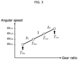
- the difference model may also be expressed by a relational expression including a transfer function representing the input/output characteristic of the two-inertia system. The equations of motion of the difference model are shown below.
- the controller 13 obtains the sum-mode instruction torque for suppressing vibrations of the left driving system and the right driving system while the vehicle 1 is running straight by applying the equivalent sum value calculated by the calculator 11 to the sum model stored in the storing unit 12. The same applies to the difference model, and the controller 13 obtains the difference-mode instruction torque for suppressing vibrations of the left driving system and the right driving system while the vehicle 1 is cornering by applying the equivalent difference value calculated by the calculator 11 to the difference model stored in the storing unit 12. Then the controller 13 controls the outputs of the left motor 2L and the right motor 2R, using the obtained sum-mode instruction torque and difference-mode instruction torque.
- the controller 13 calculates the left-motor instruction torque T LM and the right motor instruction torque T RM from the sum-mode instruction torque and the difference-mode instruction torque, and controls the left and right motors 2.
- the controller 13 outputs, as the left-motor instruction torque T LM , the half of the value obtained by subtracting the difference-mode instruction torque from the sum-mode instruction torque, and outputs, as the right-motor instruction torque T RM , the half of the sum of the sum-mode instruction torque and the difference-mode instruction torque.
- FIG. 7 is a block diagram illustrating the logic of the vibration suppressing control implemented in the vehicle control device 10.
- the vibration suppressing control is a control for obtaining the sum-mode instruction torque and the difference-mode instruction torque based on the sum model and the difference model, and is a feed-forward control (open-loop control).
- the sum-mode instruction torque is specifically exemplified by the sum-mode driving-side torque T Sin
- the difference-mode instruction torque is specifically exemplified by the difference-mode driving-side torque T Din .
- the plant in FIG. 7 represents an object (e.g., shafts and gears included in the motors 2 and the power transmission mechanism 3) located on the power transmission paths upstream of the respective axles 4.
- the sum-mode requested torque T Sds-ref (equivalent sum value) and the difference-mode requested torque T Dds-ref (equivalent difference value) calculated on the basis of the left- and right-axle requested torques T Lds-ref and T Rds-ref (left and right requested torque) are applied to the sum model and the difference model, and consequently, the sum-mode instruction torque T Sin and the difference-mode instruction torque T Din are obtained.
- the controller 13 calculates the respective torques to be outputted by the pair of motors 2 as the instruction torques T LM and T RM based on the sum-mode instruction torque T Sin and the difference-mode instruction torque T Din , and drives the pair of inverters 6 so as to obtain the torques.
- FIG. 8 shows input/output images of the vibration suppressing control at the time of straight acceleration
- FIG. 9 shows input/output images of the vibration suppressing control at the time of steady cornering.
- FIG. 8A and FIG. 9A represents graphs showing chronological changes of the left- and right-axle requested torques T Lds-ref and T Rds-ref
- each of FIG. 8B and FIG. 9B represents graphs showing chronological changes of the sum-mode requested torque T Sds-ref and the difference-mode requested torque T Dds-ref
- each of FIG. 8C and FIG. 9C represents graphs showing chronological changes of the sum-mode instruction torque T Sin and the difference-mode instruction torque T Din
- each of FIG. 8D and FIG. 9D represents graphs showing chronological changes of the left- and right-motor instruction torques T LM and T Rm .
- the sum-mode requested torque T Sds-ref is the sum of the two axle requested torques T Lds-ref and T Rds-ref
- the difference-mode requested torque T Dds-ref is the difference (i.e., 0) between the two axle requested torques T Lds-ref and T Rds-ref .
- the sum-mode requested torque T Sds-ref and the difference-mode requested torque T Dds-ref are applied to the sum model and the difference model, respectively, the sum-mode instruction torque T Sin largely changes at the rising time point t 1 and at the falling time point t 2 , and the difference-mode instruction torque T Din remains at 0, as shown in FIG. 8C .
- the left- and right-motor instruction torques T LM and T RM which are converted from the sum-mode instruction torque T Sin and the difference-mode instruction torque T Din , largely change at the time point t 1 and the time point t 2 .
- the left- and right-axle requested torques T Lds-ref and T Rds-ref rise at the time point t 3 and then fall at the time point t 4 .
- the sum-mode requested torque T Sds-ref is the sum of the two axle requested torques T Lds-ref and T Rds-ref
- the difference-mode requested torque T Dds-ref is the difference between the two axle requested torques T Lds-ref and T Rds-ref .
- the power distributing mechanism 3 may formulate the models as follows by using vector expressions.
- the symbol Z 11 represents the reduction ratio from the left driving source (left motor 2L) to the left shaft (left axle 4L)
- the symbol Z 22 represents the reduction ratio from the right driving source (right motor 2R) to the right shaft (right axle 4R)
- the symbol Z c represents the reduction ratio from the left and right driving sources to the respective opposing shafts.
- the transfer function in the above Math 14 is not proper, the transfer function is formed into a proper form by means of a second-order low-pass filter and the following equation is obtained.
- This can calculate torques (i.e., the sum-mode instruction torque T Sin and the difference-mode instruction torque T Din ) to be provided to the motors 2 to obtain the requested sum- and difference-mode axle torques T Sds-ref and T Dds-ref .
- the following Math 15 is an example of a transfer function included in the sum model and the difference model.
- non-interference parameters there are a parameter (vehicle body weight M) which appears only in the sum model and a parameter (yaw inertia I z ) which appears only in the difference model as shown in FIG. 10 .
- These parameters M and I z are parameters which do not interfere with each other in the sum model and difference model and are hereinafter referred to as "non-interference parameters".
- the non-interference parameters M and I z are used as calibrating coefficients in an adaptation process of the vehicle 1.
- calibrating and adapting of the vehicle body weight M serving as the non-interference parameter makes the sum model focusing on the running-straight state (translational motion) of the vehicle 1 possible not to affect the cornering state.
- calibrating and adapting of the yaw inertia I z serving as the non-interference parameter makes the difference mode focusing on the cornering state (yaw motion) of the vehicle 1 possible not to affect the running-straight state.
- the controller 13 controls the left and right motors 2, using the sum-mode instruction torque obtained by applying the equivalent sum value to the sum model and the difference-mode instruction torque obtained by applying the equivalent difference value to the difference model.
- This configuration can suppress vibrations of the left and right axles 4 having a vibration characteristic different between the running-straight state and the cornering state without interfering with each other.
- the requirement for complex control on decoupling can be eliminated, so that the vehicle control device 10 can be designed more simply and the vibration suppression can be achieved with a simple configuration.
- both the sum model and the difference model can be constructed as two-inertia system models.
- This configuration makes it possible to construct models of the motion states (in particular, vibration suppression) of the left and right driving systems while the vehicle 1 is running straight and while the vehicle 1 is cornering with a simple configuration.
- control considering the respective viscoelasticity can be carried out. Accordingly, the controllability of the vehicle 1 can be enhanced, and a higher vibration-suppressing effect can be obtained.
- the above sum model can be expressed by the transfer function indicating the input/output characteristic of the two-inertia system including the driving-side inertia calculated based on the inertia of the left driving source and the right driving source, the spring damper designed with the stiffness and viscosity, and the load-side inertia calculated based on the body weight of the vehicle 1.
- the vibration while the vehicle 1 is running straight can be efficiently suppressed, considering the viscoelasticity, so that the controllability of the vehicle 1 can be enhanced.
- the above difference model can be expressed by the transfer function indicating the input/output characteristic of the two-inertia system including the driving-side inertia corresponding to the equivalent inertia when a left-right difference is generated which equivalent inertia is calculated based on the torque difference amplification ratio, the spring damper designed with the stiffness and viscosity, and the load-side inertia calculated based on the yaw inertia of the vehicle 1.
- the vibration while the vehicle 1 is cornering can be efficiently suppressed, considering the viscoelasticity, so that the controllability of the vehicle 1 can be enhanced.
- the above vehicle control device 10 uses the non-interference parameters M and I z as the calibrating coefficients in the adaptation process, the adaptation in the running-straight state and the adaptation in the cornering state can be efficiently performed without interfering with each other.
- the controller 13 may consider a request of a driver of the vehicle 1 and an accelerating state of the vehicle 1.
- the request of the driver include a steering angle and an accelerator operation.
- the acceleration state include the longitudinal acceleration (front-rear G) and the lateral acceleration (lateral G).
- the controller 13 may consider either one of the request of the driver and the acceleration state or both.
- the controller 13 can execute control considering the request (e.g., a steering angle) of the driver and an accelerating state (front-rear G, lateral G) by adding the parameters of the request and the state into the equations of the transfer functions included in the sum model and the difference mode.
Landscapes
- Engineering & Computer Science (AREA)
- Mechanical Engineering (AREA)
- Transportation (AREA)
- Chemical & Material Sciences (AREA)
- Combustion & Propulsion (AREA)
- Automation & Control Theory (AREA)
- General Engineering & Computer Science (AREA)
- Power Engineering (AREA)
- Human Computer Interaction (AREA)
- Physics & Mathematics (AREA)
- Mathematical Physics (AREA)
- Electric Propulsion And Braking For Vehicles (AREA)
- Arrangement And Mounting Of Devices That Control Transmission Of Motive Force (AREA)
Applications Claiming Priority (2)
| Application Number | Priority Date | Filing Date | Title |
|---|---|---|---|
| JP2022129523 | 2022-08-16 | ||
| PCT/JP2023/025520 WO2024038707A1 (ja) | 2022-08-16 | 2023-07-11 | 車両制御装置及び車両制御方法 |
Publications (2)
| Publication Number | Publication Date |
|---|---|
| EP4574530A1 true EP4574530A1 (de) | 2025-06-25 |
| EP4574530A4 EP4574530A4 (de) | 2025-11-26 |
Family
ID=89941444
Family Applications (1)
| Application Number | Title | Priority Date | Filing Date |
|---|---|---|---|
| EP23854744.2A Pending EP4574530A4 (de) | 2022-08-16 | 2023-07-11 | Fahrzeugsteuerungsvorrichtung und fahrzeugsteuerungsverfahren |
Country Status (4)
| Country | Link |
|---|---|
| US (1) | US20260014973A1 (de) |
| EP (1) | EP4574530A4 (de) |
| JP (1) | JP7788707B2 (de) |
| WO (1) | WO2024038707A1 (de) |
Family Cites Families (6)
| Publication number | Priority date | Publication date | Assignee | Title |
|---|---|---|---|---|
| JPH0698418A (ja) * | 1992-09-16 | 1994-04-08 | Hitachi Ltd | 路面反力推定装置および左右輪差動装置および自動車モータトルク制御装置ならびに自動車 |
| CN105848946B (zh) * | 2013-12-27 | 2017-12-26 | 本田技研工业株式会社 | 车辆以及车辆的控制方法 |
| JP6954062B2 (ja) | 2017-12-01 | 2021-10-27 | 日産自動車株式会社 | 電動車両の制御方法、及び、制御装置 |
| JP7310114B2 (ja) * | 2018-10-03 | 2023-07-19 | 三菱自動車工業株式会社 | モーター制御装置 |
| CN109878347B (zh) * | 2019-03-27 | 2020-06-30 | 清华大学 | 一种多轴驱动分布式车辆的车轮扭矩分配方法 |
| US12311950B2 (en) * | 2019-10-16 | 2025-05-27 | Mitsubishi Jidosha Kogyo Kabushiki Kaisha | Motor control device for electric vehicle |
-
2023
- 2023-07-11 US US18/881,771 patent/US20260014973A1/en active Pending
- 2023-07-11 EP EP23854744.2A patent/EP4574530A4/de active Pending
- 2023-07-11 JP JP2024541453A patent/JP7788707B2/ja active Active
- 2023-07-11 WO PCT/JP2023/025520 patent/WO2024038707A1/ja not_active Ceased
Also Published As
| Publication number | Publication date |
|---|---|
| JP7788707B2 (ja) | 2025-12-19 |
| US20260014973A1 (en) | 2026-01-15 |
| EP4574530A4 (de) | 2025-11-26 |
| JPWO2024038707A1 (de) | 2024-02-22 |
| WO2024038707A1 (ja) | 2024-02-22 |
Similar Documents
| Publication | Publication Date | Title |
|---|---|---|
| EP3632733B1 (de) | Steuerungsverfahren für elektrofahrzeug und steuerungsvorrichtung | |
| EP4574599A1 (de) | Entwurfsverfahren und fahrzeugsteuerungsvorrichtung | |
| EP4382346A1 (de) | Fahrzeugsteuerungsvorrichtung | |
| EP4574532A1 (de) | Fahrzeugsteuerungsvorrichtung und fahrzeugsteuerungsverfahren | |
| JP7310114B2 (ja) | モーター制御装置 | |
| EP4382345A1 (de) | Steuerungssystem für ein fahrzeug | |
| EP4019318A1 (de) | Fahrzeugsteuerungsvorrichtung | |
| Broere et al. | Minimum-lap-time control strategies for all-wheel drive electric race cars via convex optimization | |
| EP4574534A1 (de) | Fahrzeugsteuerungsvorrichtung und fahrzeugsteuerungsverfahren | |
| CN121666325A (zh) | 车辆控制装置及车辆控制方法 | |
| US20260014973A1 (en) | Vehicle control device and vehicle control method | |
| CN121666324A (zh) | 车辆控制装置及车辆控制方法 | |
| CN121666326A (zh) | 车辆控制装置及车辆控制方法 | |
| EP4574533A1 (de) | Fahrzeugsteuerungsvorrichtung und fahrzeugsteuerungsverfahren | |
| EP4574531A1 (de) | Fahrzeugsteuerungsvorrichtung und fahrzeugsteuerungsverfahren | |
| JP7723382B2 (ja) | 車両の制御装置 | |
| US12071024B2 (en) | Driving force adjusting device and method for designing driving force adjusting device | |
| WO2025057582A1 (ja) | 車両制御装置及び車両制御方法 | |
| CN114407869A (zh) | 电动车辆的控制装置 | |
| JP2012187984A (ja) | 前後駆動力配分比制御装置 | |
| WO2025037495A1 (ja) | 車両制御装置及び車両制御方法 | |
| WO2025057583A1 (ja) | 車両制御装置及び車両制御方法 | |
| EP4177096A1 (de) | Steuerungsvorrichtung für ein fahrzeug | |
| WO2026089006A1 (ja) | 車両制御装置及び車両制御方法 |
Legal Events
| Date | Code | Title | Description |
|---|---|---|---|
| STAA | Information on the status of an ep patent application or granted ep patent |
Free format text: STATUS: THE INTERNATIONAL PUBLICATION HAS BEEN MADE |
|
| PUAI | Public reference made under article 153(3) epc to a published international application that has entered the european phase |
Free format text: ORIGINAL CODE: 0009012 |
|
| STAA | Information on the status of an ep patent application or granted ep patent |
Free format text: STATUS: REQUEST FOR EXAMINATION WAS MADE |
|
| 17P | Request for examination filed |
Effective date: 20250313 |
|
| AK | Designated contracting states |
Kind code of ref document: A1 Designated state(s): AL AT BE BG CH CY CZ DE DK EE ES FI FR GB GR HR HU IE IS IT LI LT LU LV MC ME MK MT NL NO PL PT RO RS SE SI SK SM TR |
|
| DAV | Request for validation of the european patent (deleted) | ||
| DAX | Request for extension of the european patent (deleted) | ||
| A4 | Supplementary search report drawn up and despatched |
Effective date: 20251023 |
|
| RIC1 | Information provided on ipc code assigned before grant |
Ipc: B60L 15/20 20060101AFI20251017BHEP Ipc: B60L 9/18 20060101ALI20251017BHEP Ipc: B60W 30/188 20120101ALI20251017BHEP Ipc: B60W 30/20 20060101ALI20251017BHEP Ipc: B60K 1/02 20060101ALI20251017BHEP Ipc: B60K 7/00 20060101ALI20251017BHEP Ipc: B60W 10/08 20060101ALI20251017BHEP Ipc: B60W 30/18 20120101ALI20251017BHEP |