EP4574293A1 - Metallbehälter und herstellungsverfahren dafür - Google Patents
Metallbehälter und herstellungsverfahren dafür Download PDFInfo
- Publication number
- EP4574293A1 EP4574293A1 EP23900302.3A EP23900302A EP4574293A1 EP 4574293 A1 EP4574293 A1 EP 4574293A1 EP 23900302 A EP23900302 A EP 23900302A EP 4574293 A1 EP4574293 A1 EP 4574293A1
- Authority
- EP
- European Patent Office
- Prior art keywords
- metal container
- forming
- tapered
- diameter reduction
- tapered surface
- Prior art date
- Legal status (The legal status is an assumption and is not a legal conclusion. Google has not performed a legal analysis and makes no representation as to the accuracy of the status listed.)
- Pending
Links
Images



Classifications
-
- B—PERFORMING OPERATIONS; TRANSPORTING
- B65—CONVEYING; PACKING; STORING; HANDLING THIN OR FILAMENTARY MATERIAL
- B65D—CONTAINERS FOR STORAGE OR TRANSPORT OF ARTICLES OR MATERIALS, e.g. BAGS, BARRELS, BOTTLES, BOXES, CANS, CARTONS, CRATES, DRUMS, JARS, TANKS, HOPPERS, FORWARDING CONTAINERS; ACCESSORIES, CLOSURES, OR FITTINGS THEREFOR; PACKAGING ELEMENTS; PACKAGES
- B65D7/00—Containers having bodies formed by interconnecting or uniting two or more rigid, or substantially rigid, components made wholly or mainly of metal
- B65D7/02—Containers having bodies formed by interconnecting or uniting two or more rigid, or substantially rigid, components made wholly or mainly of metal characterised by shape
- B65D7/04—Containers having bodies formed by interconnecting or uniting two or more rigid, or substantially rigid, components made wholly or mainly of metal characterised by shape of curved cross-section, e.g. cans of circular or elliptical cross-section
-
- B—PERFORMING OPERATIONS; TRANSPORTING
- B65—CONVEYING; PACKING; STORING; HANDLING THIN OR FILAMENTARY MATERIAL
- B65D—CONTAINERS FOR STORAGE OR TRANSPORT OF ARTICLES OR MATERIALS, e.g. BAGS, BARRELS, BOTTLES, BOXES, CANS, CARTONS, CRATES, DRUMS, JARS, TANKS, HOPPERS, FORWARDING CONTAINERS; ACCESSORIES, CLOSURES, OR FITTINGS THEREFOR; PACKAGING ELEMENTS; PACKAGES
- B65D1/00—Rigid or semi-rigid containers having bodies formed in one piece, e.g. by casting metallic material, by moulding plastics, by blowing vitreous material, by throwing ceramic material, by moulding pulped fibrous material or by deep-drawing operations performed on sheet material
- B65D1/22—Boxes or like containers with side walls of substantial depth for enclosing contents
- B65D1/26—Thin-walled containers, e.g. formed by deep-drawing operations
- B65D1/265—Drinking cups
-
- B—PERFORMING OPERATIONS; TRANSPORTING
- B21—MECHANICAL METAL-WORKING WITHOUT ESSENTIALLY REMOVING MATERIAL; PUNCHING METAL
- B21D—WORKING OR PROCESSING OF SHEET METAL OR METAL TUBES, RODS OR PROFILES WITHOUT ESSENTIALLY REMOVING MATERIAL; PUNCHING METAL
- B21D22/00—Shaping without cutting, by stamping, spinning, or deep-drawing
- B21D22/20—Deep-drawing
- B21D22/28—Deep-drawing of cylindrical articles using consecutive dies
-
- B—PERFORMING OPERATIONS; TRANSPORTING
- B21—MECHANICAL METAL-WORKING WITHOUT ESSENTIALLY REMOVING MATERIAL; PUNCHING METAL
- B21D—WORKING OR PROCESSING OF SHEET METAL OR METAL TUBES, RODS OR PROFILES WITHOUT ESSENTIALLY REMOVING MATERIAL; PUNCHING METAL
- B21D22/00—Shaping without cutting, by stamping, spinning, or deep-drawing
- B21D22/20—Deep-drawing
- B21D22/28—Deep-drawing of cylindrical articles using consecutive dies
- B21D22/283—Deep-drawing of cylindrical articles using consecutive dies with ram and dies aligning means
-
- B—PERFORMING OPERATIONS; TRANSPORTING
- B21—MECHANICAL METAL-WORKING WITHOUT ESSENTIALLY REMOVING MATERIAL; PUNCHING METAL
- B21D—WORKING OR PROCESSING OF SHEET METAL OR METAL TUBES, RODS OR PROFILES WITHOUT ESSENTIALLY REMOVING MATERIAL; PUNCHING METAL
- B21D22/00—Shaping without cutting, by stamping, spinning, or deep-drawing
- B21D22/20—Deep-drawing
- B21D22/30—Deep-drawing to finish articles formed by deep-drawing
-
- B—PERFORMING OPERATIONS; TRANSPORTING
- B21—MECHANICAL METAL-WORKING WITHOUT ESSENTIALLY REMOVING MATERIAL; PUNCHING METAL
- B21D—WORKING OR PROCESSING OF SHEET METAL OR METAL TUBES, RODS OR PROFILES WITHOUT ESSENTIALLY REMOVING MATERIAL; PUNCHING METAL
- B21D51/00—Making hollow objects
- B21D51/02—Making hollow objects characterised by the structure of the objects
- B21D51/10—Making hollow objects characterised by the structure of the objects conically or cylindrically shaped objects
-
- B—PERFORMING OPERATIONS; TRANSPORTING
- B21—MECHANICAL METAL-WORKING WITHOUT ESSENTIALLY REMOVING MATERIAL; PUNCHING METAL
- B21D—WORKING OR PROCESSING OF SHEET METAL OR METAL TUBES, RODS OR PROFILES WITHOUT ESSENTIALLY REMOVING MATERIAL; PUNCHING METAL
- B21D51/00—Making hollow objects
- B21D51/16—Making hollow objects characterised by the use of the objects
- B21D51/26—Making hollow objects characterised by the use of the objects cans or tins; Closing same in a permanent manner
- B21D51/2615—Edge treatment of cans or tins
- B21D51/2638—Necking
-
- B—PERFORMING OPERATIONS; TRANSPORTING
- B21—MECHANICAL METAL-WORKING WITHOUT ESSENTIALLY REMOVING MATERIAL; PUNCHING METAL
- B21D—WORKING OR PROCESSING OF SHEET METAL OR METAL TUBES, RODS OR PROFILES WITHOUT ESSENTIALLY REMOVING MATERIAL; PUNCHING METAL
- B21D51/00—Making hollow objects
- B21D51/16—Making hollow objects characterised by the use of the objects
- B21D51/26—Making hollow objects characterised by the use of the objects cans or tins; Closing same in a permanent manner
- B21D51/2646—Of particular non cylindrical shape, e.g. conical, rectangular, polygonal, bulged
-
- B—PERFORMING OPERATIONS; TRANSPORTING
- B65—CONVEYING; PACKING; STORING; HANDLING THIN OR FILAMENTARY MATERIAL
- B65D—CONTAINERS FOR STORAGE OR TRANSPORT OF ARTICLES OR MATERIALS, e.g. BAGS, BARRELS, BOTTLES, BOXES, CANS, CARTONS, CRATES, DRUMS, JARS, TANKS, HOPPERS, FORWARDING CONTAINERS; ACCESSORIES, CLOSURES, OR FITTINGS THEREFOR; PACKAGING ELEMENTS; PACKAGES
- B65D1/00—Rigid or semi-rigid containers having bodies formed in one piece, e.g. by casting metallic material, by moulding plastics, by blowing vitreous material, by throwing ceramic material, by moulding pulped fibrous material or by deep-drawing operations performed on sheet material
- B65D1/40—Details of walls
- B65D1/42—Reinforcing or strengthening parts or members
- B65D1/44—Corrugations
-
- B—PERFORMING OPERATIONS; TRANSPORTING
- B65—CONVEYING; PACKING; STORING; HANDLING THIN OR FILAMENTARY MATERIAL
- B65D—CONTAINERS FOR STORAGE OR TRANSPORT OF ARTICLES OR MATERIALS, e.g. BAGS, BARRELS, BOTTLES, BOXES, CANS, CARTONS, CRATES, DRUMS, JARS, TANKS, HOPPERS, FORWARDING CONTAINERS; ACCESSORIES, CLOSURES, OR FITTINGS THEREFOR; PACKAGING ELEMENTS; PACKAGES
- B65D21/00—Nestable, stackable or joinable containers; Containers of variable capacity
- B65D21/02—Containers specially shaped, or provided with fittings or attachments, to facilitate nesting, stacking, or joining together
- B65D21/0233—Nestable containers
Definitions
- the present invention relates to a metal container and a method for manufacturing the metal container.
- a metal container mainly made of aluminum, stainless steel, or the like includes a storage space for storing contents and an opening portion through which the contents are put in and taken out from the storage space.
- Examples of the form of the metal container include a can in which the opening portion is sealed with a lid body, and a cup with the opening portion opened.
- a tapered metal container (hereinafter, also referred to as a “tapered container”) is known.
- the metal container includes an upper opening portion, a sidewall portion, and a bottom portion, and has a tapered shape in which an inner diameter of the sidewall portion gradually decreases from the upper opening portion toward the bottom portion so that an outer diameter (lower end outer diameter) of the bottom portion becomes smaller than an inner diameter (upper end inner diameter) of the opening portion.
- Such a tapered container is manufactured by a manufacturing method in which for example, a stock material is prepared, a cup is formed by punching and drawing, the cup is redrawn so that the cup has a predetermined height and a predetermined wall thickness, after that, the cup is cut so that the cup has the predetermined height, a tip portion of the cup is rounded, the cup is drawn to form a plurality of vertical wall sections, and after that, each of the plurality of vertical wall sections is expanded in diameter using a die in order to form a sidewall portion having a tapered profile (see Patent Document 1 described below).
- Patent Document 1 JP 2021-142566 A
- the sidewall portion of the tapered container includes a relatively smooth surface of sufficient size, which serves as a display space where printing can be easily performed.
- tapered containers manufactured by a conventional manufacturing method are transported in a stacked state in which a bottom portion of one container is inserted into an opening portion of another container, forming multiple tiers.
- a phenomenon so-called blocking phenomenon
- the tapered container is also desired to have a shape that allows for easy separation after transportation.
- an example of an object of the present invention is to provide a metal container having a shape capable of avoiding a blocking phenomenon during transportation of the metal container in a stacked state while forming a sidewall portion having a surface of sufficient size, on which printing can be easily performed, and a method for manufacturing a metal container capable of effectively forming such a metal container.
- a metal container according to the present invention is a metal container including an opening portion, a sidewall portion, and a bottom portion and having a lower end outer diameter smaller than an upper end inner diameter, wherein the metal container has a shape of a bottomed cup formed by drawing a plate-like metal material and subjected to trimming, the sidewall portion has a tapered profile formed by performing diameter reduction drawing on the bottom portion side with respect to the opening portion of the bottomed cup, the sidewall portion is formed with a bulging portion bulging in a circumferential direction and a continuous tapered surface where tapered surfaces are formed in a continuous manner by performing diameter reduction drawing a plurality of times on a lower side with respect to the bulging portion.
- a method for manufacturing a metal container according to the present invention is a method for manufacturing a metal container including an opening portion, a sidewall portion, and a bottom portion and having a lower end outer diameter smaller than an upper end inner diameter, the method including: forming a bottomed cup by drawing a plate-like metal material, trimming the bottomed cup, and forming the sidewall portion having a tapered profile by performing diameter reduction drawing on the bottom portion side with respect to the opening portion of the bottomed cup, wherein in the forming the sidewall portion, a bulging portion bulging in a circumferential direction is formed, and a continuous tapered surface where tapered surfaces are formed in a continuous manner is formed by performing diameter reduction drawing a plurality of times on a lower side with respect to the bulging portion.
- a metal container having a shape capable of avoiding a blocking phenomenon during transportation of the metal container in a stacked state while forming a sidewall portion having a surface of sufficient size, on which printing can be easily performed, and a method for manufacturing a metal container capable of effectively forming such a metal container.
- a metal container 1 illustrated in FIG. 1 is manufactured.
- the metal container 1 includes an opening portion 1A, a sidewall portion 1B, and a bottom portion 1C, and is a cup-shaped container that can be substituted for a known disposable paper cup or plastic cup.
- FIG. 1 illustrates an example in which the opening portion 1A is provided with a curl 10 that is curved outward and the opening portion 1A is used in an open state, no such limitation is intended, and the opening portion 1A may be provided with a curved flange to which an outer peripheral edge portion of a lid body is wound and tightened so that the metal container 1 is used as a can container.
- the terms “above” and “below” in this specification and the like are based on an assumption that the opening portion 1A is located above and the bottom portion 1C is located below. Therefore, the "up-down direction” is a vertical direction from the opening portion 1A toward the ground surface portion with which the bottom portion 1C is in contact.
- the metal container 1 illustrated in FIG. 1 includes the sidewall portion 1B having a generally tapered profile so that an outer diameter of the bottom portion 1C (lower end outer diameter) becomes smaller than an inner diameter of the opening portion 1A (upper end inner diameter).
- a plurality of the metal containers 1 can be in a stacked state in which the bottom portion 1C of the upper metal container 1 is inserted into the opening portion 1A of the lower metal container 1, and when the metal containers 1 are not yet used, the plurality of metal containers 1 can be transported in the stacked state.
- a ratio of the inner diameter of the opening portion 1A (upper end inner diameter) to the outer diameter of the bottom portion 1C (lower end outer diameter) may be appropriately set in accordance with the use of the metal container 1 and is not particularly limited, but can be set to, for example, from 1.2:1 to 2:1.
- the upper end inner diameter is 80 mm
- the lower end outer diameter may be 50 mm.
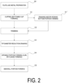
- a plate-like metal material is prepared by, for example, cutting a plate material wound in a coil shape (S0: plate-like metal material preparation step), and the plate-like metal material is punched and subjected to drawing and/or ironing to form a cup-shaped intermediate member (hereinafter, referred to as a bottomed cup) (S1: cupping step).
- the formed bottomed cup is subjected to drawing and/or ironing again and processing for forming a bottom portion (step S1') as necessary, and then a tip portion of the bottomed cup having a predetermined outer diameter, a predetermined height, and a predetermined plate thickness is subjected to trimming (S2: trimming step).
- trimming the height of the tip of the bottomed cup, which has become uneven due to the redrawing and/or ironing, is uniformly cut around the central axis, and after the trimming, the height of the tip of the bottomed cup becomes constant.
- the tip portion of the trimmed bottomed cup is subjected to tip diameter reduction drawing (S3: tip diameter reduction drawing step).
- the diameter reduction drawing performed on the tip portion is so-called necking, in which a diameter of a tip opening of the bottomed cup is reduced to form a necking portion n whose diameter is gradually reduced toward the tip, and a portion to be subsequently processed into a curl or a flange is formed.
- an opening portion including a curl or a flange is formed at the tip portion of the bottomed cup (the portion to be processed into a curl or a flange) (S4: opening portion forming step).
- a sidewall portion 1B having a generally tapered profile is formed by performing gradual diameter reduction drawing on the bottom portion 1C side with respect to the portion that has been subjected to the tip diameter reduction drawing. That is, a tapered surface t (inclined wall portion) and a vertical surface s (vertical wall portion) are alternately formed on the bottom portion 1C side of the necking portion n where the tip diameter reduction drawing has been performed, whereby a sidewall portion 1B having a generally tapered profile is formed.
- a continuous tapered surface tm where tapered surfaces t are formed in a continuous manner is formed in the vicinity of the center of the sidewall portion 1B in the vertical direction.
- the continuous tapered surface tm is the longest tapered surface (longest inclined wall portion) in the sidewall portion 1B.
- the continuous tapered surface tm has a vertical height H1 of at least from 20 to 30% with respect to the vertical height H.
- the continuous tapered surface tm having such a vertical height H1 is formed entirely in a circumferential direction.
- Such a continuous tapered surface tm has a sufficient size to serve as a display space, and is a relatively smooth surface on which printing can be easily performed.
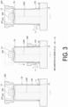
- an inner tool 100 is disposed inside a bottomed cup Cp in which the opening portion 1A including a curl 10 (or a flange 20 in FIG. 6 ) is formed, an outer tool 200 is disposed on the bottom portion 1C side of the bottomed cup Cp, and a pressing tool 300 is brought into contact with the bottom portion 1C of the bottomed cup Cp.
- the inner tool 100 is a cylindrical tool having a diameter smaller than an inner diameter of the bottomed cup Cp.
- the outer tool 200 has, on an inner surface thereof, a drawing surface 201 for performing drawing while sandwiching a sidewall of the bottomed cup Cp between an outer peripheral surface of the inner tool 100 and itself, and an inclination forming surface 202 for forming the sidewall of the bottomed cup Cp into an inclined shape.
- the inclination forming surface 202 of the outer tool 200 has a curved surface (r surface) inclined to spread outward with respect to a central axis 100P of the inner tool 100.
- the outer tool 200 is moved from the bottom portion 1C toward the opening portion 1A with respect to the fixed inner tool 100 in a direction indicated by the arrow in FIG. 3(b) in order to perform the diameter reduction drawing on the sidewall of the bottomed cup Cp, and further, the inclination forming surface 202 of the outer tool 200 is brought into contact with the bottom portion 1C side of the necking portion n, which has been subjected to the tip diameter reduction drawing, in order to form the tapered surface t.
- the bulging portion 11 when the outer tool 200 is returned to the bottom portion 1C side, on the tip side of the bottomed cup Cp, a bulging portion 11 constituted by the necking portion n and the tapered surface t is formed on the bottom portion 1C side of the curl 10.
- the bulging portion 11 can be formed by a method in which a tool (not illustrated) is brought into contact with an inner surface of the bottomed cup Cp to impress and expand it in a circumferential direction, a method in which a stepped portion is formed on the sidewall of the bottomed cup Cp by diameter reduction drawing, or the like.
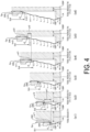
- a next stage of the sidewall portion forming step S5 will be described with reference to FIG. 4 .
- the inner tool 100 with a tool radius Tr1 is used in the above-described diameter reduction drawing at the first stage
- the inner tool 100 with a tool radius Tr2 (Tr1 > Tr2) is used to perform diameter reduction drawing at a second stage on the sidewall of the bottomed cup Cp.
- the inner diameters of the drawing surface 201 and the inclination forming surface 202 of the outer tool 200 are set in accordance with the tool diameter of the inner tool 100.
- a moving stroke St1 of the outer tool 200 is a stroke length required to form the tapered surface t of the bulging portion 11.
- a moving stroke St2 of the outer tool 200 is set to be shorter than the moving stroke St1 at the first stage, and a vertical portion s and a tapered surface t following the vertical surface s are formed on the bottom portion 1C side of the tapered surface t of the bulging portion 11.
- the inner tool 100 with a tool radius Tr2 is used in the above-described diameter reduction drawing at the second stage
- the inner tool 100 with a tool radius Tr3 (Tr2 > Tr3) is used in subsequent diameter reduction drawing at a third stage (see FIG. 4(b3) ).
- a moving stroke St3 of the outer tool 200 is set to be shorter than the moving stroke St2 at the second stage, and a vertical surface s and a tapered surface t following the vertical surface s are formed on the bottom portion 1C side of the tapered surface t formed in the diameter reduction drawing at the second stage.
- the outer tool 200 in which a radius of curvature r of the curved surface (r surface) constituting the inclination forming surface 202 is r1 is used, and the inclination forming surface 202 having the radius of curvature r1 in the outer tool 200 is brought into contact with the sidewall of the bottomed cup Cp to form the sidewall into an inclined shape, thereby forming the tapered surface t.
- the diameter reduction drawing is performed on the sidewall of the bottomed cup Cp by using the outer tool 200 in which the radius of curvature r of the curved surface constituting the inclination forming surface 202 is a radius of curvature r2 larger than the radius of curvature r1.
- the inner tool 100 with a tool radius Tr3 is used in the diameter reduction drawing at the third stage
- the inner tool 100 with a tool radius Tr4 (Tr3 > Tr4) is used to perform diameter reduction drawing on the sidewall of the bottomed cup Cp in diameter reduction drawing at a fourth stage (see FIG. 4(b4) ).
- a moving stroke St4 of the outer tool 200 is set to be shorter than the moving stroke St3 at the third stage, and a vertical surface s, and a tapered surface tm1 of a first portion, which follows the vertical surface s, of the continuous tapered surface tm are formed on the bottom portion 1C side of the tapered surface t formed by the diameter reduction drawing at the third stage.
- the tapered surface tm1 is formed by bringing the inclination forming surface 202 with the radius of curvature r2 of the outer tool 200 into contact with the sidewall of the bottomed cup Cp to form the sidewall into an inclined shape.
- the inner tool 100 with a tool radius Tr4 is used in the diameter reduction drawing at the fourth stage
- the inner tool 100 with a tool radius Tr5 (Tr4 > Tr5) is used to perform diameter reduction drawing on the sidewall of the bottomed cup Cp in diameter reduction drawing at a fifth stage (see FIG. 4(b5) ).
- a moving stroke St5 of the outer tool 200 is set to be shorter than the moving stroke St4 at the fourth stage and is brought close to the moving stroke St4, thereby forming a tapered surface tm2 of a second portion of the continuous tapered surface tm on the bottom portion 1C side of the tapered surface tm1 of the first portion of the continuous tapered surface tm formed by the diameter reduction drawing at the fourth stage.
- the tapered surface tm1 and the tapered surface tm2 are formed as continuous tapered surfaces with no vertical surface s interposed therebetween.
- the tapered surface tm2 is also formed by bringing the inclination forming surface 202 with the radius of curvature r2 of the outer tool 200 into contact with the sidewall of the bottomed cup Cp to form the sidewall into an inclined shape.
- the inner tool 100 with a tool radius Tr5 is used in the diameter reduction drawing at the fifth stage
- the inner tool 100 with a tool radius Tr6 (Tr5 > Tr6) is used to perform diameter reduction drawing on the sidewall of the bottomed cup Cp in diameter reduction drawing at a sixth stage (see FIG. 4(b6) ).
- a moving stroke St6 of the outer tool 200 is set to be shorter than the moving stroke St5 at the fifth stage and is brought close to the moving stroke St5, thereby forming a tapered surface tm3 of a third portion of the continuous tapered surface tm on the bottom portion 1C side of the tapered surface tm2 of the second portion of the continuous tapered surface tm formed by the diameter reduction drawing at the fifth stage.
- the tapered surface tm2 and the tapered surface tm3 are formed as continuous tapered surfaces with no vertical surface s interposed therebetween.
- the tapered surface tm3 is also formed by bringing the inclination forming surface 202 with the radius of curvature r2 of the outer tool 200 into contact with the sidewall of the bottomed cup Cp to form the sidewall into an inclined shape.
- the process of bringing the inclination forming surface 202 with the radius of curvature r2 of the outer tool 200 into contact with the sidewall of the bottomed cup Cp to form the sidewall into an inclined shape is continuously performed three times to form the continuous tapered surface where the tapered surfaces tm1 to tm3 are formed in a continuous manner without interposing the vertical surface s therebetween.
- the outer tool 200 in which the radius of curvature r of the inclination forming surface 202 (curved surface) is the radius of radius of curvature r2 larger than the radius of curvature r1 is used in the diameter reduction drawing at the fourth to sixth stages (see FIGS. 4(b4) to 4(b6) ). Therefore, in each of the tapered surfaces tm1 to tm3 formed by the inclination forming surface 202 with the radius of curvature r2, a length in an inclination direction from the opening portion 1A toward the bottom portion 1C is longer than that of the tapered surface t formed by the inclination forming surface 202 (curved surface) with the radius of curvature r1.
- the continuous tapered surface tm where such tapered surfaces tm1 to tm3 are formed in a continuous manner is formed as a longest tapered surface (longest inclined wall portion) having the longest length in the inclination direction from the opening portion 1A toward the bottom portion 1C.
- the outer tool 200 having the inclination forming surface 202 (curved surface) with the relatively large radius of curvature r2 is used.
- the continuous tapered surface tm of sufficient size can be formed by a small number of steps of diameter reduction drawing such as three times of the fourth to sixth stages.
- Such a continuous tapered surface tm has a sufficient size to serve as a display space, and is a relatively smooth surface on which printing can be easily performed.
- the radius of curvature r1 is not particularly limited as long as it is a value smaller than the radius of curvature r2, but may be set to from 5 to 20 mm, for example.
- r2 60 mm
- the radius of curvature r1 is larger than a value within the predetermined range, wrinkles are likely to occur on the sidewall portion.
- a center point of the inclination forming surface 202 (curved surface) in the moving direction (direction parallel to the central axis 100P) when forming the tapered surface t of the bulging portion 11 illustrated in FIG. 4(b1) is defined as p11.
- a center point of the inclination forming surface 202 (curved surface) in the moving direction (direction parallel to the central axis 100P) when forming the tapered surface t on the bottom portion 1C side of the vertical surface s connecting to the bulging portion 11 illustrated in FIG. 4(b2) is defined as p12.
- a distance between the two normal lines is defined as a pitch pt1.
- a center point of the inclination forming surface 202 (curved surface) in the moving direction (direction parallel to the central axis 100P) when forming the tapered surface tm1 of the first portion of the continuous tapered surface tm of the bulging portion 11 illustrated in FIG. 4(b4) is defined as p21.
- a center point of the inclination forming surface 202 (curved surface) in the moving direction (direction parallel to the central axis 100P) when forming the tapered surface tm2 of the second portion of the continuous tapered surface tm illustrated in FIG. 4(b5) is defined as p22.
- a magnitude relationship between the pitch pt1 and the pitch pt2 may be pt2 ⁇ pt1.
- the pitch pt1 is not particularly limited, but may be set to, for example, from 5 to 15 mm.
- the outer tool 200 having the inclination forming surface 202 (curved surface) with the radius of curvature r1 is used again to perform diameter reduction drawing on the sidewall of the bottomed cup Cp.
- the tool radius of the inner tool 100 is made smaller than the tool radius in the previous stage
- the moving stroke of the outer tool 200 is set to be shorter than the moving stroke in the previous stage
- the same drawing as the diameter reduction drawing at the second and third stages is repeated.
- the vertical surfaces s and the tapered surfaces t are alternately formed on the bottom portion 1C side of the tapered surface tm3 of the third portion in the continuous tapered surface tm formed by the diameter reduction drawing at the sixth stage.
- the sidewall portion 1B as illustrated in FIG. 1 is formed.
- the tapered surfaces t and the vertical surfaces s are repeatedly and alternately formed below the bulging portion 11, and the continuous tapered surface tm is formed in the vicinity of the center in the vertical direction, and as a result, the sidewall portion 1B has a generally tapered profile.
- an inner surface of the curl 10 is arranged so as to be in contact with an outer surface of the inner tool 100 (see FIG. 4(b2) ). This is to inhibit the curl 10 (mouth portion) from becoming an oval shape, and this also makes it possible to suppress an occurrence of blocking when the metal containers 1 are stacked.
- the metal container 1 illustrated in FIG. 1 has the bulging portion 11 below the opening portion 1A having the curl 10.
- an inner surface contact portion F2 on the inner surface of the opening portion 1A of the lower metal container 1 (bottom) is stacked in contact with an outer surface contact portion F1 on the outer surface of the sidewall portion 1B of the upper metal container 1 (top), and in one of the metal containers 1, the above-described bulging portion 11 is provided between the outer surface contact portion F1 and the inner surface contact portion F2.
- a maximum width between a normal line Lp connecting the outer surface contact portion F1 and the inner surface contact portion F2 and the outer surface of the bulging portion 11 is defined as a holding width f.
- an angle of the tapered surface t extending toward the outer surface contact portion F1 with respect to the normal line Lp is defined as an inclination angle ⁇ .
- the holding width f be 0.3 mm or more, and more preferably 0.8 mm or more. If the holding width f is smaller than this, the opening portion 1A is likely to bite into the bulging portion 11, and when vibration or impact is applied to the metal containers 1 in the stacked state during the transportation, the biting becomes larger, and the above-described blocking phenomenon is likely to occur.
- the outer diameter R11 of the bulging portion 11 is preferably smaller than an outer diameter R10 of the curl 10 (opening portion 1A). If the outer diameter R11 of the bulging portion 11 is larger than the outer diameter R10 of the curl 10, when the metal containers 1 are stored side by side, the bulging portions 11 protrude laterally beyond the curls 10, and a storage space is increased by an amount of the protrusion, which results in a deterioration in storage efficiency.
- the inclination angle ⁇ is preferably set to be within a range from 10°to 50°. If the inclination angle ⁇ becomes smaller, the same situation as that in the above-described case in which the holding width f is made smaller arises, and the frictional resistance at a time of separating the metal container 1 from the stacked state becomes larger, and thus the blocking phenomenon is more likely to occur. Note that the holding width f and the inclination angle ⁇ are adjustment factors that are related to each other, and a countermeasure against the blocking phenomenon becomes more effective by combining the conditions of the two factors.
- a distance between the upper end of the opening portion 1A of the upper metal container 1 (top) and the upper end of the opening portion 1A of the lower metal container 1 (bottom) is a stacking height hs.
- the stacking height hs affects the storage space in the height direction in the stacked state. By causing the stacking height hs to be smaller, the storage efficiency in the height direction in the state in which the metal containers 1 are stacked is increased.
- the vertical surfaces s and the tapered surfaces t are alternately formed while including the above-described bulging portion 11, and as a result, the entire sidewall portion 1B has a tapered profile.
- the continuous tapered surface tm (longest inclined wall portion) is formed in which the taper length of the tapered surface t is the longest.
- steps formed by the vertical surfaces s and the tapered surfaces t function as a slip stopper when the metal container 1 is held by hand.
- the continuous tapered surface tm in the vicinity of the center of the sidewall portion 1B can be effectively used as a display space by including a printing step for printing a display such as an image on the continuous tapered surface tm.
- a material of a base material constituting the metal container 1 aluminum, an aluminum alloy, stainless steel, steel, or the like can be used. However, by adopting aluminum, an aluminum alloy, or steel, it is possible to obtain the metal container 1, suitable for a beverage container, which is light in weight, has a gloss appearance, and allows a user to easily feel the temperature of contents (for example, cold water) by hand. Further, as a material of the metal container 1, a plate-like metal material can be used that is obtained by coating both surfaces of the base material made of aluminum, an aluminum alloy, or steel with a single layer or multiple layers of a resin film such as a PET film.
- the above-described resin-coated base material it is preferable to include a step of locally heating a portion to be processed into a curl or a flange, as a step preceding the opening portion forming step S4, illustrated in FIG. 2 , in which the curl or the flange is formed.
- the local heating for example, high-frequency heating is used to locally heat the portion to be processed on the tip side of the necking portion n, at a target temperature of 200°C ⁇ 30°C.
- the flange 20 as illustrated in FIG. 6 serves as a portion for winding and tightening an outer edge portion of a lid body.
- the metal container 1 becomes a can body for sealing contents.
- the lid body to be wound and tightened is a metal lid body, and examples thereof include a pull-tab type or stay-on-tab type partial open end (POE) can lid, a full open end (FOE) can lid, and the like, but may be a lid body of another form.
- the opening portion 1A of another form may be used, and with respect to that opening portion 1A, a lid body of another form such as a screw lid may be detachably attached.
- a lubricant (coolant) is not necessary at the sidewall portion forming step S5. This makes it possible to realize a manufacturing method in which a cleaning step is not provided between or after a series of steps. As a result, it is possible to carry out manufacturing with high productivity without washing and drying steps, and it is possible to carry out manufacturing advantageous from an environmental point of view by eliminating disposal of the lubricant.
- the inclination forming surface 202 of the outer tool 200 is not limited to the curved surface as described above, and may have another shape.
- the inclination forming surface may be a conical surface (not illustrated) inclined to spread outward with respect to the central axis 100P of the inner tool 100.
- the length in the inclination direction of the inclination forming surface 202 (conical surface) of the outer tool 200 used in the fourth to sixth diameter reduction drawing for forming the continuous tapered surface tm is preferably longer than that of the outer tool 200 used in the first to third diameter reduction drawing for forming the tapered surface t.
- the continuous tapered surface tm of sufficient size can be formed with a small number of steps of the diameter reduction drawing.
- the method for manufacturing the metal container 1 by forming the sidewall portion 1B by the diameter reduction drawing from the bottom portion 1C side, it is possible to cope with various shapes.
- the bulging portion 11 bulging in the circumferential direction is formed, and the continuous tapered surface tm where the tapered surfaces t are formed in a continuous manner is formed by performing diameter reduction drawing a plurality of times on the lower side than the bulging portion 11.
- the metal container 1 capable of effectively forming a container having a shape capable of avoiding a blocking phenomenon during transportation of the metal container in the stacked state while forming the sidewall portion 1B having a surface of sufficient size, on which printing can be easily performed.
- 1 Metal container 1A Opening portion, 1B Sidewall portion, 1C Bottom portion, 10 Curl, 11 Bulging portion, 20 Flange, 100 Inner tool, 100P Central axis, 200 Outer tool, 201 Drawing surface, 202 Inclination forming surface, 300 Pressing tool, t Tapered surface, tm Continuous tapered surface, s Vertical surface, n Necking portion, S0 Plate-like metal material preparation step, S1 Cupping step, S2 Trimming step, S3 Tip diameter reduction drawing step, S4 Opening portion forming step, S5 Sidewall portion forming step, St1 to St6 Moving stroke, Tr1 to Tr6 Tool radius, Cp Bottomed cup, F1 Outer surface contact portion, F2 Inner surface contact portion, r, r1, r2 Radius of curvature, R10 Outer diameter of opening portion 1A, R11 Outer diameter of bulging portion 11
Landscapes
- Engineering & Computer Science (AREA)
- Mechanical Engineering (AREA)
- Ceramic Engineering (AREA)
- Containers Having Bodies Formed In One Piece (AREA)
- Stackable Containers (AREA)
- Shaping Metal By Deep-Drawing, Or The Like (AREA)
Applications Claiming Priority (2)
| Application Number | Priority Date | Filing Date | Title |
|---|---|---|---|
| JP2022197006A JP2024082848A (ja) | 2022-12-09 | 2022-12-09 | 金属容器及びその製造方法 |
| PCT/JP2023/036854 WO2024122180A1 (ja) | 2022-12-09 | 2023-10-11 | 金属容器及びその製造方法 |
Publications (1)
| Publication Number | Publication Date |
|---|---|
| EP4574293A1 true EP4574293A1 (de) | 2025-06-25 |
Family
ID=91378784
Family Applications (1)
| Application Number | Title | Priority Date | Filing Date |
|---|---|---|---|
| EP23900302.3A Pending EP4574293A1 (de) | 2022-12-09 | 2023-10-11 | Metallbehälter und herstellungsverfahren dafür |
Country Status (5)
| Country | Link |
|---|---|
| US (1) | US20250223074A1 (de) |
| EP (1) | EP4574293A1 (de) |
| JP (1) | JP2024082848A (de) |
| CN (1) | CN119894776A (de) |
| WO (1) | WO2024122180A1 (de) |
Families Citing this family (1)
| Publication number | Priority date | Publication date | Assignee | Title |
|---|---|---|---|---|
| JP2025136855A (ja) * | 2024-03-08 | 2025-09-19 | 東洋製罐株式会社 | 金属容器及びその製造方法 |
Family Cites Families (4)
| Publication number | Priority date | Publication date | Assignee | Title |
|---|---|---|---|---|
| JP4681143B2 (ja) * | 2001-03-30 | 2011-05-11 | 大和製罐株式会社 | 金属薄板製の容器用部品の製造方法 |
| US10875076B2 (en) | 2017-02-07 | 2020-12-29 | Ball Corporation | Tapered metal cup and method of forming the same |
| AU2019396327B2 (en) * | 2018-12-10 | 2022-07-21 | Ball Corporation | Tapered metal cup and method of forming the same |
| JP7484612B2 (ja) * | 2020-09-23 | 2024-05-16 | 東洋製罐株式会社 | 容器の製造方法および容器の製造装置 |
-
2022
- 2022-12-09 JP JP2022197006A patent/JP2024082848A/ja active Pending
-
2023
- 2023-10-11 CN CN202380067223.7A patent/CN119894776A/zh active Pending
- 2023-10-11 EP EP23900302.3A patent/EP4574293A1/de active Pending
- 2023-10-11 WO PCT/JP2023/036854 patent/WO2024122180A1/ja not_active Ceased
-
2025
- 2025-03-25 US US19/090,101 patent/US20250223074A1/en active Pending
Also Published As
| Publication number | Publication date |
|---|---|
| US20250223074A1 (en) | 2025-07-10 |
| WO2024122180A1 (ja) | 2024-06-13 |
| JP2024082848A (ja) | 2024-06-20 |
| CN119894776A (zh) | 2025-04-25 |
Similar Documents
| Publication | Publication Date | Title |
|---|---|---|
| US10464707B2 (en) | Shaped metal container and method for making same | |
| EP0664169B1 (de) | Verfahren zum Formen eines metallischen Behalters | |
| US5626049A (en) | Draw-process systems for fabricating one-piece can bodies | |
| US8313003B2 (en) | Can manufacture | |
| US4522049A (en) | Aluminum alloy food can body and method for making same | |
| US20250223074A1 (en) | Metal container and manufacturing method for same | |
| JP2022052374A (ja) | 容器の製造方法および容器の製造装置 | |
| US11407022B2 (en) | Process and apparatus for the production of a can body by wall ironing | |
| EP1944101B1 (de) | Verfahren zum tiefziehen/abstreckziehen einer harzbeschichteten metallplatte | |
| JP7272481B1 (ja) | 金属容器の製造方法 | |
| EP4442595A1 (de) | Metallbehälter und herstellungsverfahren dafür | |
| JP2790072B2 (ja) | シームレス缶の製造方法 | |
| JP4670543B2 (ja) | 2ピース缶及びその製造方法、並びに2ピース缶用鋼板 | |
| KR100982120B1 (ko) | 2피스 캔 및 그 제조방법, 및 2피스 캔용 강판 | |
| US7526938B2 (en) | Can manufacture | |
| JP4229650B2 (ja) | ボトル型缶 | |
| US20140197181A1 (en) | Three-piece can | |
| EP4470932A1 (de) | Stapelbarer metallbecher | |
| WO2025187199A1 (ja) | 金属容器及びその製造方法 | |
| JPH09253772A (ja) | 2ピースシームレスアルミニウム容器とその製造方法 | |
| JP2001335018A (ja) | 缶胴の補強構造 | |
| EP2586720A1 (de) | Dreiteilige Dose | |
| KR20230044499A (ko) | 용기의 제조 방법 및 용기의 제조 장치 | |
| JP2025153182A (ja) | リフォーム用金属容器及び蓋嵌合型金属容器の製造法 | |
| JP5073931B2 (ja) | 2ピース缶及びその製造方法、並びに2ピース缶用鋼板 |
Legal Events
| Date | Code | Title | Description |
|---|---|---|---|
| STAA | Information on the status of an ep patent application or granted ep patent |
Free format text: STATUS: THE INTERNATIONAL PUBLICATION HAS BEEN MADE |
|
| PUAI | Public reference made under article 153(3) epc to a published international application that has entered the european phase |
Free format text: ORIGINAL CODE: 0009012 |
|
| STAA | Information on the status of an ep patent application or granted ep patent |
Free format text: STATUS: REQUEST FOR EXAMINATION WAS MADE |
|
| 17P | Request for examination filed |
Effective date: 20250318 |
|
| AK | Designated contracting states |
Kind code of ref document: A1 Designated state(s): AL AT BE BG CH CY CZ DE DK EE ES FI FR GB GR HR HU IE IS IT LI LT LU LV MC ME MK MT NL NO PL PT RO RS SE SI SK SM TR |
|
| DAV | Request for validation of the european patent (deleted) | ||
| DAX | Request for extension of the european patent (deleted) |