EP4572096A1 - Rotorblechpaket für eine elektrische maschine mit abschlussblechen zur halten eines magneten - Google Patents
Rotorblechpaket für eine elektrische maschine mit abschlussblechen zur halten eines magneten Download PDFInfo
- Publication number
- EP4572096A1 EP4572096A1 EP24214562.1A EP24214562A EP4572096A1 EP 4572096 A1 EP4572096 A1 EP 4572096A1 EP 24214562 A EP24214562 A EP 24214562A EP 4572096 A1 EP4572096 A1 EP 4572096A1
- Authority
- EP
- European Patent Office
- Prior art keywords
- rotor
- recess
- magnet
- lamination stack
- shaft
- Prior art date
- Legal status (The legal status is an assumption and is not a legal conclusion. Google has not performed a legal analysis and makes no representation as to the accuracy of the status listed.)
- Pending
Links
Images


Classifications
-
- H—ELECTRICITY
- H02—GENERATION; CONVERSION OR DISTRIBUTION OF ELECTRIC POWER
- H02K—DYNAMO-ELECTRIC MACHINES
- H02K1/00—Details of the magnetic circuit
- H02K1/06—Details of the magnetic circuit characterised by the shape, form or construction
- H02K1/22—Rotating parts of the magnetic circuit
- H02K1/27—Rotor cores with permanent magnets
- H02K1/2706—Inner rotors
- H02K1/272—Inner rotors the magnetisation axis of the magnets being perpendicular to the rotor axis
- H02K1/274—Inner rotors the magnetisation axis of the magnets being perpendicular to the rotor axis the rotor consisting of two or more circumferentially positioned magnets
- H02K1/2753—Inner rotors the magnetisation axis of the magnets being perpendicular to the rotor axis the rotor consisting of two or more circumferentially positioned magnets the rotor consisting of magnets or groups of magnets arranged with alternating polarity
- H02K1/276—Magnets embedded in the magnetic core, e.g. interior permanent magnets [IPM]
- H02K1/2766—Magnets embedded in the magnetic core, e.g. interior permanent magnets [IPM] having a flux concentration effect
-
- H—ELECTRICITY
- H02—GENERATION; CONVERSION OR DISTRIBUTION OF ELECTRIC POWER
- H02K—DYNAMO-ELECTRIC MACHINES
- H02K1/00—Details of the magnetic circuit
- H02K1/06—Details of the magnetic circuit characterised by the shape, form or construction
- H02K1/22—Rotating parts of the magnetic circuit
- H02K1/27—Rotor cores with permanent magnets
- H02K1/2706—Inner rotors
- H02K1/272—Inner rotors the magnetisation axis of the magnets being perpendicular to the rotor axis
- H02K1/274—Inner rotors the magnetisation axis of the magnets being perpendicular to the rotor axis the rotor consisting of two or more circumferentially positioned magnets
- H02K1/2753—Inner rotors the magnetisation axis of the magnets being perpendicular to the rotor axis the rotor consisting of two or more circumferentially positioned magnets the rotor consisting of magnets or groups of magnets arranged with alternating polarity
- H02K1/276—Magnets embedded in the magnetic core, e.g. interior permanent magnets [IPM]
-
- H—ELECTRICITY
- H02—GENERATION; CONVERSION OR DISTRIBUTION OF ELECTRIC POWER
- H02K—DYNAMO-ELECTRIC MACHINES
- H02K15/00—Processes or apparatus specially adapted for manufacturing, assembling, maintaining or repairing of dynamo-electric machines
- H02K15/02—Processes or apparatus specially adapted for manufacturing, assembling, maintaining or repairing of dynamo-electric machines of stator or rotor bodies
- H02K15/03—Processes or apparatus specially adapted for manufacturing, assembling, maintaining or repairing of dynamo-electric machines of stator or rotor bodies having permanent magnets
-
- H—ELECTRICITY
- H02—GENERATION; CONVERSION OR DISTRIBUTION OF ELECTRIC POWER
- H02K—DYNAMO-ELECTRIC MACHINES
- H02K15/00—Processes or apparatus specially adapted for manufacturing, assembling, maintaining or repairing of dynamo-electric machines
- H02K15/02—Processes or apparatus specially adapted for manufacturing, assembling, maintaining or repairing of dynamo-electric machines of stator or rotor bodies
- H02K15/03—Processes or apparatus specially adapted for manufacturing, assembling, maintaining or repairing of dynamo-electric machines of stator or rotor bodies having permanent magnets
- H02K15/035—Processes or apparatus specially adapted for manufacturing, assembling, maintaining or repairing of dynamo-electric machines of stator or rotor bodies having permanent magnets on the rotor
Definitions
- the invention relates to a rotor core for a rotor of an electrical machine, comprising a plurality of axially stacked rotor cores, each of which has a recess (or a hole), wherein the recesses form a magnetic pocket for receiving a rotor magnet. Furthermore, the invention relates to a rotor for an electrical machine, an electrical machine having a rotor, a vehicle having an electrical machine, and a manufacturing method for a rotor of an electrical machine.
- a permanent magnet rotor according to the prior art has a rotor lamination stack with a plurality of rotor laminations stacked axially one on top of the other, wherein the axial direction runs parallel to the rotation axis of the rotor.
- rotor magnets Arranged within the rotor core are several permanent magnets, referred to as "rotor magnets,” which serve to generate a rotor magnetic field.
- the rotor core has magnetic pockets, each extending from one axial side of the rotor core to its opposite axial side.
- the rotor has a rotor shaft that extends axially through a central through-hole in the rotor core.
- the rotor magnets can be arranged in the rotor core before the rotor core is mounted on the rotor shaft.
- the core is aligned so that its rotational axis is vertical.
- the rotor magnets are then inserted from above into the magnet pockets of the rotor core. This poses a risk that the rotor magnets could fall or slip out of the core due to gravity. This risk also exists during a subsequent manufacturing step, in which the rotor core is pushed onto the rotor shaft from above, and during transport of the rotor core to this manufacturing step.
- the rotor magnets can be cast with a potting compound to securely fasten the rotor magnets so that they do not become loose or come off during operation of the electrical machine.
- the object of the invention is to prevent the rotor magnets of a rotor from falling out of its rotor core during assembly of the rotor.
- a rotor lamination stack according to the invention, which has an end plate arranged on its axial side with a further recess which is axially aligned with the recess of the adjacent rotor lamination and is narrowed compared to the recess of the adjacent rotor lamination.
- the constriction prevents a rotor magnet inserted into the magnet pocket from slipping or falling out of the rotor core. Furthermore, the recess in the end plate allows liquid casting compound to flow out during the subsequent casting of the rotor magnet. can flow out of the rotor core at the bottom, thus avoiding the formation of unwanted air pockets in the potting compound, which remains in the magnetic pocket.
- each rotor lamination may have further recesses that form additional magnetic pockets for accommodating additional rotor magnets.
- the end plate may also have further recesses, each of which is axially aligned with a recess in the adjacent rotor lamination and narrower than this recess.
- the rotor core may have an axial through-opening through which a rotor shaft can be guided.
- the recess of the end plate is identical to the recess of the adjacent rotor lamination, except for one or more projections forming the constriction that extend into the recess of the end plate.
- the punching tool used to produce the end plate requires little modification compared to the punching tool used to produce the adjacent rotor lamination.
- the identical design can be understood to mean that both recesses have the same shape, arrangement, and orientation on the rotor lamination.
- the recess of the end plate has two opposing edge sections, with the projections arranged on both edge sections.
- the projections are distributed across both edge sections. This prevents the tilting of a rotor magnet resting against the constriction.
- the two edge sections can, for example, be straight, running parallel to each other or forming an angle. Alternatively, it is also possible for all projections to be arranged on only one edge section.
- a projection can be arranged on a first edge portion, with a point opposite the projection on the second edge portion lying between two projections arranged on the second edge portion, for example, in the middle between the two projections. Tilting of the rotor magnet can thus be prevented with a minimal number of projections, namely only three.
- one or more projections can have a circular segment-shaped end section. This makes the end section particularly stable, preventing unwanted bending of the end section.
- a rotor according to the invention which has a rotor shaft with a rotor core according to the invention arranged, in particular fastened, thereon.
- a rotor magnet is accommodated in the magnet pocket of the rotor core, which axially rests against the constriction. The constriction prevents the rotor magnet from slipping or falling out of the magnet pocket during assembly of the rotor.
- additional rotor magnets can be accommodated in the magnet pocket, wherein the rotor magnets can be arranged axially in a row.
- the rotor can have additional magnet pockets, each of which accommodates one or more magnets.
- a free space is formed between the rotor magnet and the plurality of axially stacked rotor laminations.
- This free space is intended for a potting compound with which the rotor magnet can be potted.
- the recess in the end plate is then arranged so that it is axially aligned with the free space. This allows potting compound that has flowed into the free space to flow out of the free space particularly well, thus preventing the formation of undesirable air pockets in the potting compound remaining in the free space.
- another rotor lamination stack is arranged on the rotor shaft, corresponding to the aforementioned rotor lamination stack.
- the magnetic poles of both rotor laminations are rotated relative to each other around the rotor shaft or the rotor's rotational axis.
- the magnetic poles of one of the rotor laminations are rotated relative to the magnetic poles of the other rotor lamination stack. This improves the rotor's rotational behavior.
- each of the rotor magnets is encapsulated with a potting compound. This reliably secures the rotor magnets in the rotor core, preventing them from becoming loose or dislodged during operation of the electric machine.
- an electrical machine according to the invention which has a rotor according to the invention and a stator with respect to which the rotor is rotatably mounted.
- the object is achieved with a vehicle having an electric machine according to the invention which is designed to drive the vehicle.
- a further rotor lamination stack corresponding to the rotor lamination stack is pushed onto the rotor shaft or fastened to the rotor shaft so that the magnetic poles of both rotor lamination stacks are rotated relative to each other around the rotor shaft.
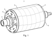
- Figure 1 shows a schematic perspective view of a skewed rotor 1 according to the invention.
- the rotor 1 belongs to an electrical machine, which also has a stator, relative to which the rotor 1 is rotatably mounted.
- the rotor 1 has a cylindrical rotor body 2 with six axially arranged rotor lamination stacks 3.
- a rotor according to the invention can also have a different number of rotor lamination stacks, for example, one, two, three, four, five, seven, eight, nine, or ten rotor lamination stacks.
- the rotor body 2 is mounted on a rotor shaft 4 which extends through an axial through-opening of the rotor body 2 along a (virtual) rotation axis of the rotor 1.
- the rotor laminations 3 each have a plurality of magnetic poles formed by rotor magnets (not visible), wherein the magnetic poles are rotated relative to one another around the rotor shaft 4.
- the magnetic poles of each rotor lamination 3 are rotated relative to the magnetic poles of at least one adjacent rotor lamination 3.
- the rotation of the rotor laminations 3 is V-shaped, which is symbolized by the thin lines.
- the rotor laminations of a rotor according to the invention can also be rotated differently, for example, linearly.
- rotor end plates 5 are arranged on opposite axial sides of the rotor body 2.
- the rotor body 2 with the rotor end plates 5 is axially fixed between a shaft shoulder and a shaft nut 6.
- a rotor body according to the invention can also be axially fixed to a rotor shaft in a different way, including with a press fit and/or without rotor end plates.
- Figure 2 shows an axial section through the rotor 1 from Figure 1 , where the axial section runs through a rotor core 3.
- the rotor lamination stack 3 has a plurality of axially stacked rotor laminations 7, of which Figure 2 only one is visible, which covers the rotor laminations 7 located behind it.
- the rotor laminations 7 are identically designed and stacked congruently.
- the rotor lamination stack 3 has several magnetic pockets 8, each formed by recesses 9 in the rotor laminations 7.
- a rotor magnet 10 is accommodated in each magnet pocket 8.
- several rotor magnets can be accommodated in a magnet pocket of a rotor core according to the invention.
- the rotor magnets 10 are arranged in eight groups, each comprising four rotor magnets 10 arranged in a double V shape and forming a magnetic pole.
- a different number and arrangement of rotor magnets is also possible in a rotor core according to the invention.
- the magnetic poles generate a rotor magnetic field.
- each rotor magnet 10 At the radial ends of each rotor magnet 10, a free space 11 is formed, which can be filled with a potting compound, for example, a resin.
- the potting compound reliably fixes the rotor magnets 10 in the rotor core 3, preventing the rotor magnets 10 from becoming loose or detached during operation of the electric machine.
- the rotor shaft 4 is visible, for which hatching has been omitted for reasons of clarity.
- the rotor lamination stack 3 also includes a cover plate arranged on an axial side of the rotor lamination stack 3, which Figure 2 is not visible.
- Figure 3 shows another axial section through the rotor 1 from Figure 1 , whereby the axial section runs on the outside of the end plate 12.
- the end plate 12 has a plurality of recesses 13, each of which is axially aligned with a magnetic pocket 8 of the rotor lamination stack 3 or a recess 9 of the adjacent rotor lamination 7 of the rotor lamination stack 3.
- each recess 13 is narrower than the corresponding recess 9 of the adjacent rotor lamination 7 or magnetic pocket 8.
- each recess 13 of the end plate 12 is identical to the corresponding recess 9 of the adjacent rotor plate 7, apart from three projections forming the constriction, which protrude into the recess 13 and, with reference to Figure 5 be explained in more detail.
- the rotor magnets 10 accommodated in the magnet pockets 8 and the rotor shaft 4 are visible.
- the rotor magnets 10 each axially rest against the constriction or the three projections forming the constriction of the corresponding recess 13.
- Figure 4 shows a section of a rotor lamination 7 of a rotor lamination package 3 of the rotor 1 from Figure 1 .
- the recesses 9 which, together with similar recesses 9 of the other rotor laminations 7 of the rotor lamination stack 3 to which the rotor lamination 7 belongs, form the magnetic pockets 8 for receiving the rotor magnets 10.
- Each recess 9 is elongated and has two opposing straight edge portions 15.
- two types of recesses 9 are present—namely, larger recesses 9 and smaller recesses 9.
- the larger recesses 9 are arranged in pairs in a V-shape, and the smaller recesses 9 are also arranged in pairs in a V-shape, so that two larger recesses 9 and two smaller recesses 9 form a double V arrangement.
- each recess 9 At the ends of each recess 9 are two free areas, which, in the fully assembled rotor 1, together with the corresponding areas of the other rotor laminations 7 of the rotor lamination stack 3, form the free spaces 11.
- Each free space 11 is bounded by a rotor magnet 10 and the rotor lamination stack 3.
- Figure 5 shows a section of a cover plate 11 of a rotor core 3 of the rotor 1 from Figure 1 .
- the recesses 13 are visible, which are each aligned with a recess 9 of the adjacent rotor lamination 7 and are narrowed compared to this recess 9.
- each recess 13 of the end plate 12 is identical to the corresponding recess 9 of the adjacent rotor plate 7, except for three projections 14 forming the constriction, which project into the recess 9.
- a different number of projections may also be provided, for example, one, two, four, five, or six projections.
- the projections 14 of a recess 13 are arranged on two opposite edge sections 16 of the recess 13. Alternatively, the projections could also be arranged on only one of two opposite edge sections of the recess.
- the projections 14 of the recess 13 are arranged such that a projection 14 is arranged on a first edge portion 16, and a point opposite the projection on the second edge portion 16 lies midway between two projections 14 arranged on the second edge portion 16. Furthermore, the projections 14 are designed such that each projection 14 has a circular segment-shaped end portion.
- each recess 13 is axially aligned with the free spaces 11 of the associated magnetic pocket 8.
- two free areas of the recess 13, which are formed at its ends, are axially aligned with the free spaces 11.
- a further rotor lamination stack 3 corresponding to the rotor lamination stack 3 can be pushed onto the rotor shaft 4 so that the magnetic poles of both rotor lamination stacks 3 are rotated relative to each other around the rotor shaft 4.
Landscapes
- Engineering & Computer Science (AREA)
- Power Engineering (AREA)
- Manufacturing & Machinery (AREA)
- Permanent Field Magnets Of Synchronous Machinery (AREA)
- Iron Core Of Rotating Electric Machines (AREA)
Abstract
Ein Rotorblechpaket (3) für einen Rotor (1) einer elektrischen Maschine weist eine Mehrzahl axial aufeinander gestapelter Rotorbleche (7) auf, die jeweils eine Ausnehmung (9) aufweisen, wobei die Ausnehmungen (9) eine Magnettasche (8) zum Aufnehmen eines Rotormagneten (10) bilden, wobei das Rotorblechpaket (3) ein an seiner Axialseite angeordnetes Abschlussblech (12) mit einer weiteren Ausnehmung (13) aufweist, welche mit der Ausnehmung (9) des benachbarten Rotorblechs (7) axial fluchtet und gegenüber der Ausnehmung (9) des benachbarten Rotorblechs (7) verengt ist.
Description
- Die Erfindung betrifft ein Rotorblechpaket für einen Rotor einer elektrischen Maschine, welches eine Mehrzahl axial aufeinander gestapelter Rotorbleche aufweist, die jeweils eine Ausnehmung (bzw. ein Loch) aufweisen, wobei die Ausnehmungen eine Magnettasche zum Aufnehmen eines Rotormagneten bilden. Ferner betrifft die Erfindung einen Rotor für eine elektrische Maschine, eine elektrische Maschine mit einem Rotor, ein Fahrzeug mit einer elektrischen Maschine und ein Herstellungsverfahren für einen Rotor einer elektrischen Maschine.
- Ein permanenterregter Rotor gemäß dem Stand der Technik weist ein Rotorblechpaket mit einer Mehrzahl axial aufeinander gestapelter Rotorbleche auf, wobei die Axialrichtung parallel zur Rotationsachse des Rotors verläuft.
- In dem Rotorblechpaket sind mehrere als "Rotormagnete" bezeichnete Permanentmagnete angeordnet, die zum Erzeugen eines Rotormagnetfelds dienen. Zum Aufnehmen der Rotormagnete verfügt das Rotorblechpaket über Magnettaschen, die sich jeweils von einer Axialseite des Rotorblechpakets bis zu seiner gegenüberliegenden Axialseite erstrecken. Weiterhin weist der Rotor eine Rotorwelle auf, die sich axial durch eine zentrale Durchgangsöffnung des Rotorblechpakets erstreckt.
- Bei Herstellen des Rotors können die Rotormagnete in dem Rotorblechpaket angeordnet werden, bevor das Rotorblechpaket auf der Rotorwelle montiert wird.
- So wird insbesondere bei einem sogenannten "geschrägten" Rotor verfahren. Auf der Rotorwelle eines solchen Rotors werden mehrere Rotorblechpakete bzw. Rotorsegmente montiert, wobei die Magnetpole eines Rotorblechpakets gegeneinander den Magnetpolen eines anderen Rotorblechpakets um die Rotationsachse des Rotors verdreht sind.
- Zum Anordnen der Rotormagnete in dem Rotorblechpaket wird das Rotorblechpaket derart ausgerichtet, dass seine Rotationsachse vertikal verläuft. Danach werden die Rotormagnete von oben in die Magnettaschen des Rotorblechpakets eingeführt. Dabei besteht die Gefahr, dass die Rotormagnete aufgrund der Schwerkraft nach unten aus dem Rotorblechpaket herausfallen bzw. herausrutschen. Diese Gefahr besteht auch bei einem weiteren Herstellungsschritt, bei dem das Rotorblechpaket von oben auf die Rotorwelle aufgeschoben wird, und beim Transport des Rotorblechpakets zu diesem Herstellungsschritt.
- Nach dem Befestigen aller Rotorblechpakete auf der Rotorwelle können die Rotormagnete mit einer Vergussmasse vergossen werden, um die Rotormagnete zuverlässig zu befestigen, so dass sich die Rotormagnete beim Betrieb der elektrischen Maschine nicht lockern bzw. lösen.
- Die Aufgabe der Erfindung besteht darin, ein Herausfallen der Rotormagnete eines Rotors aus dessen Rotorblechpaket beim Montieren des Rotors zu vermeiden.
- Die Aufgabe wird mit einem Rotorblechpaket gemäß der Erfindung gelöst, welches ein an seiner Axialseite angeordnetes Abschlussblech mit einer weiteren Ausnehmung aufweist, welche mit der Ausnehmung des benachbarten Rotorblechs axial fluchtet und gegenüber der Ausnehmung des benachbarten Rotorblechs verengt ist.
- Bei Montieren des Rotors, wenn das Rotorblechpaket derart ausgerichtet ist, dass seine Rotationsache vertikal verläuft und sich das Abschlussblech an der Unterseite des Rotorblechpakets befindet, blockiert die Verengung das Herausrutschen bzw. Herausfallen eines in die Magnettasche eingesetzten Rotormagneten aus dem Rotorblechpaket. Ferner ermöglicht die Ausnehmung des Abschlussblechs, dass beim späteren Vergießen des Rotormagneten flüssige Vergussmasse nach unten aus dem Rotorblechpaket abfließen kann, womit das Entstehen unerwünschter Lufteinschlüsse in der Vergussmasse vermieden wird, welche in der Magnettasche verbleibt.
- Neben der genannten Ausnehmung kann jedes Rotorblech weitere Ausnehmungen aufweisen, die weitere Magnettaschen zum Aufnehmen weiterer Rotormagneten bilden. In diesem Fall kann auch das Abschlussblech weitere Ausnehmungen aufweisen, die jeweils mit einer Ausnehmung des benachbarten Rotorblechs axial fluchten und gegenüber dieser Ausnehmung verengt sind.
- Weiterhin kann das Rotorblechpaket eine axiale Durchgangsöffnung aufweisen, durch die eine Rotorwelle geführt werden kann.
- Bei einer Ausführungsform des Rotorblechpakets ist die Ausnehmung des Abschlussblechs identisch mit der Ausnehmung des benachbarten Rotorblechs ausgebildet, abgesehen von einem oder mehreren die Verengung bildenden Vorsprüngen, die in die Ausnehmung des Abschlussblechs ragen. Dadurch muss das zum Herstellen des Abschlussblechs verwendete Stanzwerkzeug gegenüber dem zum Herstellen des benachbarten Rotorblechs verwendeten Stanzwerkzeug kaum modifiziert werden. Die identische Ausbildung kann so verstanden werden, dass beide Ausnehmungen dieselbe Form, Anordnung und Ausrichtung auf dem Rotorblech haben.
- Optional weist die Ausnehmung des Abschlussblechs zwei einander gegenüberliegende Randabschnitte auf, wobei die Vorsprünge an beiden Randabschnitten angeordnet sind. Mit anderen Worten sind die Vorsprünge auf beide Randabschnitte verteilt. Damit kann das Verkippen eines an der Verengung anliegenden Rotormagneten vermieden werden. Die beiden Randabschnitte können beispielsweise gerade ausgebildet sein, wobei sie parallel zueinander verlaufen oder einen Winkel bilden können. Alternativ dazu ist es auch möglich, dass alle Vorsprünge an nur einem Randabschnitt angeordnet sind.
- Insbesondere kann ein Vorsprung an einem ersten Randabschnitt angeordnet sein, wobei ein Punkt, der dem Vorsprung auf dem zweiten Randabschnitt gegenüberliegt, zwischen zwei an dem zweiten Randabschnitt angeordneten Vorsprüngen liegt, beispielsweise in der Mitte zwischen beiden Vorsprüngen. Damit kann ein Verkippen des Rotormagneten mit einer minimalen Anzahl von Vorsprüngen, nämlich nur drei Vorsprüngen, vermieden werden.
- Ferner ist es möglich, dass ein Vorsprung oder jeder Vorsprung einen kreissegmentförmigen Endabschnitt aufweist. Damit ist der Endabschnitt besonders stabil ausgebildet, so dass ein unerwünschtes Verbiegen des Endabschnitts vermieden wird.
- Die Aufgabe wird ferner mit einem Rotor gemäß der Erfindung gelöst, der eine Rotorwelle mit einem darauf angeordneten, insbesondere befestigten, erfindungsgemäßen Rotorblechpaket aufweist. In der Magnettasche des Rotorblechpakets ist ein Rotormagnet aufgenommen, der an der Verengung axial anliegt. Mit der Verengung wird vermieden, dass der Rotormagnet beim Montieren des Rotors aus der Magnettasche herausrutscht bzw. herausfällt.
- In der Magnettasche können neben dem Rotormagneten weitere Rotormagnete aufgenommen sein, wobei die Rotormagnete insbesondere axial aneinandergereiht sein können. Ferner kann der Rotor weitere Magnettaschen aufweisen, in denen jeweils ein Magnet oder mehrere Magnete derart aufgenommen sind.
- Bei einer Ausführungsform des Rotors ist zwischen dem Rotormagnet und der Mehrzahl axial aufeinander gestapelter Rotorbleche ein Freiraum gebildet, der für eine Vergussmasse vorgesehen ist, mit welcher der Rotormagnet vergossen werden kann. Die Ausnehmung des Abschlussblechs ist dann so angeordnet, dass sie mit dem Freiraum axial fluchtet. Dadurch kann in den Freiraum geflossene Vergussmasse besonders gut aus dem Freiraum abfließen, womit das Entstehen unerwünschter Lufteinschlüsse in der im Freiraum verbleibenden Vergussmasse vermieden wird.
- Bei einer weiteren Ausführungsform des Rotors ist auf der Rotorwelle ein weiteres Rotorblechpaket angeordnet, das dem vorgenannten Rotorblechpaket entspricht. Hierbei sind Magnetpole beider Rotorblechpakete um die Rotorwelle bzw. Rotationsachse des Rotors gegeneinander verdreht. Mit anderen Worten sind Magnetpole eines der Rotorblechpakete gegenüber Magnetpolen des anderen Rotorblechpakets verdreht. Auf diese Weise lässt sich das Rotationsverhalten des Rotors verbessern.
- Bei einer weiteren Ausführungsform des Rotors ist jeder der Rotormagnete mit einer Vergussmasse vergossen. Dadurch sind die Rotormagnete zuverlässig im Rotorblechpaket fixiert, sodass sich die Rotormagnete beim Betrieb der elektrischen Maschine nicht lockern oder lösen.
- Die Aufgabe wird ferner mit einer elektrischen Maschine gemäß der Erfindung gelöst, die einen erfindungsgemäßen Rotor und einen Stator aufweist, bezüglich dem der Rotor drehbar gelagert ist.
- Weiterhin wird die Aufgabe mit einem Fahrzeug gelöst, das eine erfindungsgemäße elektrische Maschine aufweist, die zum Antreiben des Fahrzeugs eingerichtet ist.
- Außerdem wir die Aufgabe mit einem Herstellungsverfahren für einen Rotor gemäß der Erfindung gelöst, bei dem folgende Verfahrensschritte ausgeführt werden:
- Ausrichten eines Rotorblechpakets, so dass eine Rotationsachse des Rotorblechpakets vertikal verläuft und das Abschlussblech des Rotorblechpakets an dessen Unterseite angeordnet ist,
- Einsetzen des Rotormagneten in die Magnettasche des ausgerichteten Rotorblechpakets, so dass der Rotormagnet an der Verengung axial anliegt,
- Ausrichten der Rotorwelle, so dass die Rotorwelle vertikal verläuft, und
- Aufschieben des ausgerichteten Rotorblechpakets mit dem Rotormagneten auf die Rotorwelle.
- Bei einer Ausführungsform des Herstellungsverfahrens wird ein dem Rotorblechpaket entsprechendes weiteres Rotorblechpaket auf die Rotorwelle aufgeschoben bzw. auf der Rotorwelle befestigt, so dass Magnetpole beider Rotorblechpakete um die Rotorwelle gegeneinander verdreht sind.
- Im Folgenden werden Ausführungsformen der Erfindung anhand der folgenden schematischen Figuren näher erläutert. Es zeigen
- Figur 1
- eine perspektivische Ansicht eines geschrägten Rotors gemäß der Erfindung,
- Figur 2
- einen Axialschnitt durch den Rotor aus
Figur 1 , - Figur 3
- einen weiteren Axialschnitt durch den Rotor aus
Figur 1 , - Figur 4
- einen Ausschnitt eines Rotorblechs des Rotors aus
Figur 1 , - Figur 5
- einen Ausschnitt eines Abschlussblechs des Rotors aus
Figur 1 . -
Figur 1 zeigt eine schematische perspektivische Darstellung eines geschrägten Rotors 1 gemäß der Erfindung. Der Rotor 1 gehört zu einer elektrischen Maschine, die außerdem einen Stator aufweist, gegenüber dem der Rotor 1 drehbar gelagert ist. - Der Rotor 1 weist einen zylinderförmigen Rotorkörper 2 mit sechs axial aneinandergereihten Rotorblechpaketen 3 auf. Ein erfindungsgemäßer Rotor kann aber auch eine andere Anzahl von Rotorblechpaketen aufweisen, zum Beispiel, ein, zwei, drei, vier, fünf, sieben, acht, neun oder zehn Rotorblechpakete.
- Der Rotorkörper 2 ist auf einer Rotorwelle 4 montiert, die sich durch eine axiale Durchgangsöffnung des Rotorkörpers 2 entlang einer (virtuellen) Rotationsachse des Rotors 1 erstreckt.
- Die Rotorblechpakete 3 weisen jeweils mehrere von Rotormagneten (nicht sichtbar) gebildete Magnetpole auf, wobei die Magnetpole gegeneinander um die Rotorwelle 4 verdreht sind. Insbesondere sind die Magnetpole jedes Rotorblechpakets 3 gegenüber den Magnetpolen zumindest eines benachbarten Rotorblechpakets 3 verdreht. Im vorliegenden Fall ist die Verdrehung der Rotorblechpakete 3 V-förmig, was mit den dünnen Linien symbolisiert wird. Die Rotorblechpakete eines erfindungsgemäßen Rotors können jedoch auch anders verdreht sein, beispielsweise linear.
- Ferner sind zwei kreisförmige Rotorendplatten 5 an gegenüberliegenden Axialseiten des Rotorkörpers 2 angeordnet. Der Rotorkörper 2 mit den Rotorendplatten 5 ist zwischen einer Wellenschulter und einer Wellenmutter 6 axial fixiert. Ein erfindungsgemäßer Rotorkörper kann aber auch auf eine andere Weise auf einer Rotorwelle axial fixiert sein, unter anderem mit einer Presspassung und/oder unter Verzicht auf Rotorendplatten.
-
Figur 2 zeigt einen Axialschnitt durch den Rotor 1 ausFigur 1 , wobei der Axialschnitt durch ein Rotorblechpaket 3 verläuft. - Das Rotorblechpaket 3 weist eine Mehrzahl axial aufeinander gestapelter Rotorbleche 7 auf, von denen in
Figur 2 nur eines sichtbar ist, welches die dahinterliegenden Rotorbleche 7 verdeckt. Die Rotorbleche 7 sind nämlich identisch ausgebildet und deckungsgleich gestapelt. Ferner weist das Rotorblechpaket 3 mehrere Magnettaschen 8 auf, die jeweils von Ausnehmungen 9 der Rotorbleche 7 gebildet sind. - In jeder Magnettasche 8 ist ein Rotormagnet 10 aufgenommen. Alternativ dazu können auch mehrere Rotormagnete in einer Magnettasche eines erfindungsgemäßen Rotorblechpakets aufgenommen sein.
- Im vorliegenden Fall sind die Rotormagnete 10 in acht Gruppen angeordnet, die jeweils vier Doppel-V-förmig angeordnete Rotormagnete 10 umfassen und einen Magnetpol bilden. Es ist aber auch eine andere Anzahl und Anordnung von Rotormagneten in einem erfindungsgemäßen Rotorblechpaket möglich. Mit den Magnetpolen wird ein Rotormagnetfeld erzeugt.
- An den radialen Enden jedes Rotormagneten 10 ist jeweils ein Freiraum 11 gebildet, der mit einer Vergussmasse gefüllt werden kann, beispielsweise mit einem Harz. Mit der Vergussmasse werden die Rotormagnete 10 zuverlässig im Rotorblechpaket 3 fixiert, sodass sich die Rotormagnete 10 beim Betrieb der elektrischen Maschine nicht lockern oder lösen.
- Weiterhin ist die Rotorwelle 4 sichtbar, bei der aus Gründen der Übersichtlichkeit auf eine Schraffur verzichtet wurde. Zu dem Rotorblechpaket 3 gehört neben der Mehrzahl von Rotorblechen 7 auch ein an einer Axialseite des Rotorblechpakets 3 angeordnetes Abschlussblech, das in
Figur 2 nicht sichtbar ist. -
Figur 3 zeigt einen weiteren Axialschnitt durch den Rotor 1 ausFigur 1 , wobei der Axialschnitt an der Außenseite des Abschlussblechs 12 verläuft. - Das Abschlussblech 12 weist mehrere Ausnehmungen 13 auf, die jeweils mit einer Magnettasche 8 des Rotorblechpakets 3 bzw. einer Ausnehmung 9 des benachbarten Rotorblechs 7 des Rotorblechpakets 3 axial fluchten. Erfindungsgemäß ist jede Ausnehmung 13 gegenüber der zugehörigen Ausnehmung 9 des benachbarten Rotorblechs 7 bzw. Magnettasche 8 verengt.
- Im vorliegenden Fall ist jede Ausnehmung 13 des Abschlussblechs 12 identisch mit der zugehörigen Ausnehmung 9 des benachbarten Rotorblechs 7 ausgebildet, abgesehen von drei die Verengung bildenden Vorsprüngen, die in die Ausnehmung 13 ragen und Bezug nehmend auf
Figur 5 näher erläutert werden. - Weiterhin sind die in den Magnettaschen 8 aufgenommenen Rotormagnete 10 und die Rotorwelle 4 sichtbar. Die Rotormagnete 10 liegen jeweils an der Verengung bzw. den drei die Verengung bildenden Vorsprüngen der zugehörigen Ausnehmung 13 axial an.
-
Figur 4 zeigt einen Ausschnitt eines Rotorblechs 7 eines Rotorblechpakets 3 des Rotors 1 ausFigur 1 . - Sichtbar sind insbesondere die Ausnehmungen 9, welche gemeinsam mit gleichartigen Ausnehmungen 9 der anderen Rotorbleche 7 des Rotorblechpakets 3, zu dem das Rotorblech 7 gehört, die Magnettaschen 8 zum Aufnehmen der Rotormagnete 10 bilden.
- Jede Ausnehmung 9 ist länglich ausgebildet und weist zwei einander gegenüberliegende gerade Randabschnitte 15 auf. Im vorliegenden Fall sind zwei Arten von Ausnehmungen 9 vorhanden - nämlich größere Ausnehmungen 9 und kleinere Ausnehmungen 9. Die größeren Ausnehmungen 9 sind paarweise V-förmig angeordnet und die kleineren Ausnehmungen 9 sind ebenfalls paarweise V-förmig angeordnet, so dass zwei größere Ausnehmungen 9 und zwei kleinere Ausnehmungen 9 eine Doppel-V-Anordnung bilden.
- An den Enden jeder Ausnehmung 9 befinden sich zwei Freibereiche, die bei dem fertig montierten Rotor 1 gemeinsam mit den entsprechenden Bereichen der anderen Rotorbleche 7 des Rotorblechpakets 3 die Freiräume 11 bilden. Jeder Freiraum 11 wird von einem Rotormagneten 10 und dem Rotorblechpaket 3 begrenzt.
-
Figur 5 zeigt einen Ausschnitt eines Abschlussblechs 11 eines Rotorblechpakets 3 des Rotors 1 ausFigur 1 . - Sichtbar sind insbesondere die Ausnehmungen 13, welche jeweils mit einer Ausnehmung 9 des benachbarten Rotorblechs 7 fluchten und gegenüber dieser Ausnehmung 9 verengt sind.
- Im vorliegenden Fall ist jede Ausnehmung 13 des Abschlussblechs 12 identisch mit der zugehörigen Ausnehmung 9 des benachbarten Rotorblechs 7 ausgebildet, abgesehen von drei die Verengung bildenden Vorsprüngen 14, die in die Ausnehmung 9 ragen. Anstelle von drei Vorsprüngen kann auch eine andere Anzahl von Vorsprüngen vorgesehen sein, beispielsweise, ein, zwei, vier, fünf oder sechs Vorsprünge.
- Die Vorsprünge 14 einer Ausnehmung 13 sind an zwei gegenüberliegenden Randabschnitten 16 der Ausnehmung 13 ausgeordnet. Alternativ dazu könnten die Vorsprünge auch an nur einem von zwei gegenüberliegenden Randabschnitten der Ausnehmung angeordnet sein.
- Insbesondere sind die Vorsprünge 14 der Ausnehmung 13 derart angeordnet, dass ein Vorsprung 14 an einem ersten Randabschnitt 16 angeordnet ist und ein Punkt, der dem Vorsprung auf dem zweiten Randabschnitt 16 gegenüberliegt, in der Mitte zwischen zwei an dem zweiten Randabschnitt 16 angeordneten Vorsprüngen 14 liegt. Ferner sind die Vorsprünge 14 so gestaltet, dass jeder Vorsprung 14 einen kreissegmentförmigen Endabschnitt aufweist.
- Bei dem Rotorblechpaket 3 fluchtet jede Ausnehmung 13 axial mit den Freiräumen 11 der zugehörigen Magnettasche 8. Insbesondere fluchten zwei Freibereiche der Ausnehmung 13, die an deren Enden ausgebildet sind, axial mit den Freiräumen 11.
- Beim Herstellen des Rotors 1 können folgende Schritte ausgeführt werden:
- Ausrichten eines erfindungsgemäßen Rotorblechpakets 3, so dass die Rotationsachse des Rotorblechpakets 3 vertikal verläuft und das Abschlussblech 12 des Rotorblechpakets 3 an seiner Unterseite angeordnet ist,
- Einsetzen von Rotormagneten 10 in die Magnettaschen 8 des ausgerichteten Rotorblechpakets 3, so dass die Rotormagneten 10 an den Verengungen der Ausnehmungen 13 des Abschlussblechs 12 axial anliegen,
- Ausrichten der Rotorwelle 4, so dass die Rotorwelle vertikal verläuft, und
- Aufschieben des ausgerichteten Rotorblechpakets 3 mit den Rotormagneten 10 auf die Rotorwelle 4.
- Zusätzlich kann ein dem Rotorblechpaket 3 entsprechendes weiteres Rotorblechpaket 3 auf die Rotorwelle 4 aufgeschoben werden, so dass Magnetpole beider Rotorblechpakete 3 um die Rotorwelle 4 gegeneinander verdreht sind.
-
- 1
- Rotor
- 2
- Rotorkörper
- 3
- Rotorblechpaket
- 4
- Rotorwelle
- 5
- Rotorendplatten
- 6
- Wellenmutter
- 7
- Rotorblech
- 8
- Magnettasche
- 9
- Ausnehmung
- 10
- Rotormagnete
- 11
- Freiraum
- 12
- Abschlussblech
- 13
- Ausnehmung
- 14
- Vorsprung
- 15
- Randabschnitt
- 16
- Randabschnitt
Claims (13)
- Rotorblechpaket (3) für einen Rotor (1) einer elektrischen Maschine, welches eine Mehrzahl axial aufeinander gestapelter Rotorbleche (7) aufweist, die jeweils eine Ausnehmung (9) aufweisen,wobei die Ausnehmungen (9) eine Magnettasche (8) zum Aufnehmen eines Rotormagneten (10) bilden,wobei das Rotorblechpaket (3) ein an seiner Axialseite angeordnetes Abschlussblech (12) mit einer weiteren Ausnehmung (13) aufweist, welche mit der Ausnehmung (9) des benachbarten Rotorblechs (7) axial fluchtet und gegenüber der Ausnehmung (9) des benachbarten Rotorblechs (7) verengt ist.
- Rotorblechpaket (3) gemäß Anspruch 1, wobei die Ausnehmung (13) des Abschlussblechs (12) identisch mit der Ausnehmung (9) des benachbarten Rotorblechs (7) ausgebildet ist, abgesehen von einem oder mehreren die Verengung bildenden Vorsprüngen (14), die in die Ausnehmung (13) des Abschlussblechs (12) ragen.
- Rotorblechpaket (3) gemäß Anspruch 2, wobei die Ausnehmung (13) des Abschlussblechs (12) zwei einander gegenüberliegende Randabschnitte (16) aufweist und die Vorsprünge (14) an beiden Randabschnitten (16) angeordnet sind.
- Rotorblechpaket (3) gemäß Anspruch 3, wobei ein Vorsprung (14) an einem ersten Randabschnitt (16) angeordnet ist und ein Punkt, der dem Vorsprung (14) auf dem zweiten Randabschnitt (16) gegenüberliegt, zwischen zwei an dem zweiten Randabschnitt (16) angeordneten Vorsprüngen (14) liegt.
- Rotorblechpaket (3) gemäß einem der Ansprüche 2 bis 4, wobei jeder Vorsprung (14) einen kreissegmentförmigen Endabschnitt aufweist.
- Rotor (1) für eine elektrische Maschine, mit einer Rotorwelle (4) und einem auf der Rotorwelle (4) angeordneten Rotorblechpaket (3) gemäß einem der vorhergehenden Ansprüche, wobei in der Magnettasche (8) ein Rotormagnet (10) aufgenommen ist, der an der Verengung axial anliegt.
- Rotor (1) gemäß Anspruch 6, wobei zwischen dem Rotormagneten (10) und der Mehrzahl axial aufeinander gestapelter Rotorbleche (7) ein Freiraum (11) gebildet ist und die Ausnehmung (13) des Abschlussblechs (12) mit dem Freiraum (11) axial fluchtet.
- Rotor (1) gemäß Anspruch 6 oder 7, mit einem dem Rotorblechpaket (3) entsprechenden weiteren Rotorblechpaket (3), das auf der Rotorwelle (4) angeordnet ist, wobei Magnetpole beider Rotorblechpakete (3) um die Rotorwelle (4) gegeneinander verdreht sind.
- Rotor (1) gemäß einem der Ansprüche 6 bis 8, wobei die Rotormagnete (10) mit einer Vergussmasse vergossen sind.
- Elektrische Maschine mit einem Rotor (1) gemäß einem der Ansprüche 6 bis 9 und einem Stator, gegenüber dem der Rotor (1) drehbar gelagert ist.
- Fahrzeug mit einer elektrischen Maschine gemäß Anspruch 10, die zum Antreiben des Fahrzeugs eingerichtet ist.
- Herstellungsverfahren für einen Rotor (1) einer elektrischen Maschine gemäß einem der Ansprüche 6 bis 9, mit den Schritten- Ausrichten eines Rotorblechpakets (3), so dass die Rotationsachse des Rotorblechpakets (3) vertikal verläuft und das Abschlussblech (12) des Rotorblechpakets (3) an seiner Unterseite angeordnet ist,- Einsetzen eines Rotormagneten (10) in die Magnettasche (8) des ausgerichteten Rotorblechpakets (3), so dass der Rotormagnet (10) an der Verengung axial anliegt,- Ausrichten der Rotorwelle (4), so dass die Rotorwelle (4) vertikal verläuft, und- Aufschieben des ausgerichteten Rotorblechpakets (3) mit dem Rotormagneten (10) auf die Rotorwelle (4).
- Herstellungsverfahren gemäß Anspruch 12, bei dem ein dem Rotorblechpaket (3) entsprechendes weiteres Rotorblechpaket (3) auf die Rotorwelle (4) aufgeschoben wird, so dass Magnetpole beider Rotorblechpakete (3) um die Rotorwelle (4) gegeneinander verdreht sind.
Applications Claiming Priority (1)
| Application Number | Priority Date | Filing Date | Title |
|---|---|---|---|
| DE102023134858.2A DE102023134858A1 (de) | 2023-12-12 | 2023-12-12 | Rotorblechpaket für einen Rotor einer elektrischen Maschine mit einem Abschlussblech |
Publications (1)
| Publication Number | Publication Date |
|---|---|
| EP4572096A1 true EP4572096A1 (de) | 2025-06-18 |
Family
ID=93648406
Family Applications (1)
| Application Number | Title | Priority Date | Filing Date |
|---|---|---|---|
| EP24214562.1A Pending EP4572096A1 (de) | 2023-12-12 | 2024-11-21 | Rotorblechpaket für eine elektrische maschine mit abschlussblechen zur halten eines magneten |
Country Status (4)
| Country | Link |
|---|---|
| US (1) | US20250192628A1 (de) |
| EP (1) | EP4572096A1 (de) |
| CN (1) | CN120150447A (de) |
| DE (1) | DE102023134858A1 (de) |
Citations (3)
| Publication number | Priority date | Publication date | Assignee | Title |
|---|---|---|---|---|
| EP2136454A1 (de) * | 2007-04-12 | 2009-12-23 | Toyota Jidosha Kabushiki Kaisha | Rotor, verfahren zu seiner herstellung und elektrisches fahrzeug |
| EP3349333A1 (de) * | 2017-01-11 | 2018-07-18 | Toyota Jidosha Kabushiki Kaisha | Rotor für eine elektrische drehmaschine |
| DE102021213955A1 (de) * | 2021-12-08 | 2023-06-15 | Mahle International Gmbh | Verfahren zur Herstellung eines Rotors eines Elektromotors |
Family Cites Families (6)
| Publication number | Priority date | Publication date | Assignee | Title |
|---|---|---|---|---|
| JP4566319B2 (ja) * | 2000-03-10 | 2010-10-20 | 三菱電機株式会社 | 永久磁石モータの永久磁石埋め込み型回転子 |
| JP2007037202A (ja) * | 2003-10-31 | 2007-02-08 | Neomax Co Ltd | 永久磁石埋め込み型モータ用回転子、その組立方法および組立装置 |
| DE102006056873A1 (de) * | 2006-12-01 | 2008-06-05 | Siemens Ag | Permanentmagnetrotor mit Aufbiegungen zum Fixieren der Permanentmagnete des Rotorpaketes |
| EP2437377B1 (de) * | 2010-10-04 | 2013-06-19 | ZF Friedrichshafen AG | Permanentmagnet-Rotor für einen Elektromotor |
| US8692432B2 (en) * | 2010-12-07 | 2014-04-08 | Regal Beloit America, Inc. | Permanent magnet rotors and methods of assembling the same |
| DE102011078054A1 (de) * | 2011-06-24 | 2012-12-27 | Robert Bosch Gmbh | Lamellenpaket mit Magnetfixiernasen für einen Rotor oder Stator einer Elektromaschine |
-
2023
- 2023-12-12 DE DE102023134858.2A patent/DE102023134858A1/de active Pending
-
2024
- 2024-11-21 EP EP24214562.1A patent/EP4572096A1/de active Pending
- 2024-12-11 CN CN202411816822.7A patent/CN120150447A/zh active Pending
- 2024-12-11 US US18/977,009 patent/US20250192628A1/en active Pending
Patent Citations (3)
| Publication number | Priority date | Publication date | Assignee | Title |
|---|---|---|---|---|
| EP2136454A1 (de) * | 2007-04-12 | 2009-12-23 | Toyota Jidosha Kabushiki Kaisha | Rotor, verfahren zu seiner herstellung und elektrisches fahrzeug |
| EP3349333A1 (de) * | 2017-01-11 | 2018-07-18 | Toyota Jidosha Kabushiki Kaisha | Rotor für eine elektrische drehmaschine |
| DE102021213955A1 (de) * | 2021-12-08 | 2023-06-15 | Mahle International Gmbh | Verfahren zur Herstellung eines Rotors eines Elektromotors |
Also Published As
| Publication number | Publication date |
|---|---|
| US20250192628A1 (en) | 2025-06-12 |
| CN120150447A (zh) | 2025-06-13 |
| DE102023134858A1 (de) | 2025-06-12 |
Similar Documents
| Publication | Publication Date | Title |
|---|---|---|
| EP1306960B1 (de) | Elektromotor | |
| DE10115852A1 (de) | Elektrische Umlaufvorrichtung sowie zugehöriges Herstellungsverfahren | |
| EP1497901A1 (de) | Magnetischer rückschluss und permanentmagnetfixierung eines rotors | |
| DE102008020778A1 (de) | Rotor für eine Synchronmaschine, Herstellungsverfahren für einen derartigen Rotor sowie Synchronmaschine mit einem derartigen Rotor | |
| DE3327744A1 (de) | Verfahren zum auswuchten von bewickelten laeufern elektrischer maschinen | |
| DE102022104587A1 (de) | Rotor, elektrische drehvorrichtung und antriebsvorrichtung | |
| DE102007013738B4 (de) | Elektrische Maschine mit Klauenpolstator | |
| EP3817195A1 (de) | Rotor für eine elektrische maschine, zugehöriges herstellungsverfahren und elektrische maschine zum antreiben eines fahrzeugs | |
| DE60320165T2 (de) | Drehende elektrische Maschine | |
| DE102022107849A1 (de) | Rotoreinrichtung und Verfahren zur Herstellung einer Rotoreinrichtung einer elektrischen Maschine | |
| DE102007021946A1 (de) | Elektromotor | |
| DE102023134858A1 (de) | Rotorblechpaket für einen Rotor einer elektrischen Maschine mit einem Abschlussblech | |
| DE202023002960U1 (de) | Rotor für eine elektrische Maschine mit einem Rotorblechpaket mit einem Abschlussblech | |
| DE102024111406A1 (de) | Elektromotorrotorbaugruppe mit magnethaltemerkmal | |
| WO2006082134A1 (de) | Linearmotor mit kraftwelligkeitsausgleich | |
| DE102023203604A1 (de) | Lamelle, Lamellenpaket, Verfahren zur Herstellung eines Lamellenpakets, elektrischer Antrieb sowie Kraftfahrzeug | |
| EP4409727A1 (de) | Rotor für eine elektrische maschine mit einem verbindungskanal | |
| WO2023274633A1 (de) | Rotor mit einer endplatte mit einer vertiefung | |
| DE102018127501A1 (de) | EC-Motor für ein elektrisches Handwerkzeug sowie Verfahren zur Herstellung eines Rotors für einen EC-Motor | |
| EP3035497B1 (de) | Karusselltür | |
| DE102021204845A1 (de) | Lamellenpaket für eine elektrische Maschine sowie Verfahren zur Fertigung des Lamellenpakets | |
| DE60310352T2 (de) | Flacher Schrittmotor mit zwei in der gleichen Ebene liegenden Spulen | |
| WO2022058237A1 (de) | Rotor für eine elektrische maschine, verfahren zur herstellung eines rotors für eine elektrische maschine und elektrische maschine für ein fahrzeug | |
| DE102021206832A1 (de) | Rotor mit einer Endplatte mit einer Einfüllöffnung | |
| DE102021200809A1 (de) | Eine Rotorlamelle, ein Rotorblechpaket, ein Rotor und ein Verfahren zum Fertigen eines Rotors |
Legal Events
| Date | Code | Title | Description |
|---|---|---|---|
| PUAI | Public reference made under article 153(3) epc to a published international application that has entered the european phase |
Free format text: ORIGINAL CODE: 0009012 |
|
| STAA | Information on the status of an ep patent application or granted ep patent |
Free format text: STATUS: REQUEST FOR EXAMINATION WAS MADE |
|
| STAA | Information on the status of an ep patent application or granted ep patent |
Free format text: STATUS: EXAMINATION IS IN PROGRESS |
|
| 17P | Request for examination filed |
Effective date: 20241121 |
|
| AK | Designated contracting states |
Kind code of ref document: A1 Designated state(s): AL AT BE BG CH CY CZ DE DK EE ES FI FR GB GR HR HU IE IS IT LI LT LU LV MC ME MK MT NL NO PL PT RO RS SE SI SK SM TR |
|
| 17Q | First examination report despatched |
Effective date: 20250528 |