EP4572071A1 - Fotovoltaisches stromerzeugungssystem und steuerungsverfahren dafür - Google Patents
Fotovoltaisches stromerzeugungssystem und steuerungsverfahren dafür Download PDFInfo
- Publication number
- EP4572071A1 EP4572071A1 EP23856202.9A EP23856202A EP4572071A1 EP 4572071 A1 EP4572071 A1 EP 4572071A1 EP 23856202 A EP23856202 A EP 23856202A EP 4572071 A1 EP4572071 A1 EP 4572071A1
- Authority
- EP
- European Patent Office
- Prior art keywords
- voltage
- power
- output
- direct current
- frequency
- Prior art date
- Legal status (The legal status is an assumption and is not a legal conclusion. Google has not performed a legal analysis and makes no representation as to the accuracy of the status listed.)
- Pending
Links
Images


Classifications
-
- H—ELECTRICITY
- H02—GENERATION; CONVERSION OR DISTRIBUTION OF ELECTRIC POWER
- H02J—ELECTRIC POWER NETWORKS; CIRCUIT ARRANGEMENTS OR SYSTEMS FOR SUPPLYING OR DISTRIBUTING ELECTRIC POWER; SYSTEMS FOR STORING ELECTRIC ENERGY
- H02J3/00—Circuit arrangements for AC mains or AC distribution networks
- H02J3/38—Arrangements for feeding a single network from two or more generators or sources in parallel; Arrangements for feeding already energised networks from additional generators or sources in parallel
- H02J3/381—Dispersed generators
-
- H—ELECTRICITY
- H02—GENERATION; CONVERSION OR DISTRIBUTION OF ELECTRIC POWER
- H02J—ELECTRIC POWER NETWORKS; CIRCUIT ARRANGEMENTS OR SYSTEMS FOR SUPPLYING OR DISTRIBUTING ELECTRIC POWER; SYSTEMS FOR STORING ELECTRIC ENERGY
- H02J3/00—Circuit arrangements for AC mains or AC distribution networks
- H02J3/001—Arrangements for handling faults or abnormalities, e.g. emergencies or contingencies
- H02J3/0014—Arrangements for handling faults or abnormalities, e.g. emergencies or contingencies for preventing or reducing power oscillations in networks
- H02J3/00142—Oscillations concerning frequency
-
- H—ELECTRICITY
- H02—GENERATION; CONVERSION OR DISTRIBUTION OF ELECTRIC POWER
- H02J—ELECTRIC POWER NETWORKS; CIRCUIT ARRANGEMENTS OR SYSTEMS FOR SUPPLYING OR DISTRIBUTING ELECTRIC POWER; SYSTEMS FOR STORING ELECTRIC ENERGY
- H02J3/00—Circuit arrangements for AC mains or AC distribution networks
- H02J3/002—Flicker reduction, e.g. compensation of flicker introduced by non-linear load
-
- H—ELECTRICITY
- H02—GENERATION; CONVERSION OR DISTRIBUTION OF ELECTRIC POWER
- H02J—ELECTRIC POWER NETWORKS; CIRCUIT ARRANGEMENTS OR SYSTEMS FOR SUPPLYING OR DISTRIBUTING ELECTRIC POWER; SYSTEMS FOR STORING ELECTRIC ENERGY
- H02J3/00—Circuit arrangements for AC mains or AC distribution networks
- H02J3/38—Arrangements for feeding a single network from two or more generators or sources in parallel; Arrangements for feeding already energised networks from additional generators or sources in parallel
- H02J3/46—Controlling the sharing of generated power between the generators, sources or networks
-
- H—ELECTRICITY
- H02—GENERATION; CONVERSION OR DISTRIBUTION OF ELECTRIC POWER
- H02J—ELECTRIC POWER NETWORKS; CIRCUIT ARRANGEMENTS OR SYSTEMS FOR SUPPLYING OR DISTRIBUTING ELECTRIC POWER; SYSTEMS FOR STORING ELECTRIC ENERGY
- H02J2101/00—Supply or distribution of decentralised, dispersed or local electric power generation
- H02J2101/20—Dispersed power generation using renewable energy sources
- H02J2101/22—Solar energy
- H02J2101/24—Photovoltaics
-
- Y—GENERAL TAGGING OF NEW TECHNOLOGICAL DEVELOPMENTS; GENERAL TAGGING OF CROSS-SECTIONAL TECHNOLOGIES SPANNING OVER SEVERAL SECTIONS OF THE IPC; TECHNICAL SUBJECTS COVERED BY FORMER USPC CROSS-REFERENCE ART COLLECTIONS [XRACs] AND DIGESTS
- Y02—TECHNOLOGIES OR APPLICATIONS FOR MITIGATION OR ADAPTATION AGAINST CLIMATE CHANGE
- Y02E—REDUCTION OF GREENHOUSE GAS [GHG] EMISSIONS, RELATED TO ENERGY GENERATION, TRANSMISSION OR DISTRIBUTION
- Y02E10/00—Energy generation through renewable energy sources
- Y02E10/50—Photovoltaic [PV] energy
- Y02E10/56—Power conversion systems, e.g. maximum power point trackers
Definitions
- This application relates to the photovoltaic field, and in particular, to a photovoltaic power generation system and a photovoltaic power generation system control method.
- the new energy power system may be disconnected from the power grid.
- This application provides a photovoltaic power generation system and a photovoltaic power generation system control method, to implement fast frequency support.
- an embodiment of this application provides a photovoltaic power generation system, including a direct current converter, an inverter, and an inverter controller.
- the direct current converter is configured to connect an output of a photovoltaic module and perform voltage conversion on a direct current output by the photovoltaic module;
- the inverter is configured to convert a direct current output by the direct current converter into an alternating current and output the alternating current to a power grid;
- the first controller is configured to generate a first drive signal based on two of a first voltage of the direct current output by the direct current converter, an active power output by the inverter, and an operating parameter of the power grid, and control an operating state of the inverter based on the first drive signal.
- the first voltage is a voltage amplitude of the direct current output by the direct current converter
- the operating parameter of the power grid includes one or more of a reactive current, an active current, a reactive power, an active power, a voltage amplitude, and a power grid frequency.
- the first controller may generate a corresponding drive signal based on any two of the foregoing three parameters, and adjust the operating state of the inverter, so that the alternating current output by the inverter can implement a frequency support function.
- the first controller is specifically configured to: generate a first active power control signal based on a first voltage difference and a first frequency difference; and generate the first drive signal based on the first active power control signal and the operating parameter of the power grid.
- the first voltage is the voltage amplitude of the direct current output by the direct current converter
- the operating parameter of the power grid includes one or more of the reactive current, the active current, the reactive power, the active power, the voltage amplitude, and the power grid frequency.
- droop control between the active power output by the inverter and the direct current voltage may be performed based on the first voltage difference between the first voltage and the first reference voltage
- droop control between the active power output by the inverter and the power grid frequency may be performed based on a frequency difference
- an active power for implementing frequency support is determined according to the foregoing two droop control policies.
- the first controller is specifically configured to: generate a first modulated wave signal based on the first active power control signal and the operating parameter of the power grid; and generate the first drive signal based on the first modulated wave signal and a first carrier signal, where the first carrier signal is a sine wave signal with a fixed period or a pulse signal.
- the first carrier signal is adjusted based on the first modulated wave signal for controlling an output power of the inverter, to obtain the first drive signal for controlling a conduction time sequence of switching transistors in the inverter, so as to adjust the active power output by the inverter.
- the first controller is specifically configured to: obtain a first power based on the first voltage difference and a first droop coefficient, where the first droop coefficient is determined based on a correspondence between the direct current output by the direct current converter and the active power output by the inverter; obtain a second power based on the first frequency difference and a second droop coefficient, where the second droop coefficient is determined based on a correspondence between the power grid frequency and the active power output by the inverter; and generate the first active power control signal based on the first power, the second power, and a third power.
- the third power is an initial active power delivered by a plant management system, and the plant management system is configured to control an operating state of the photovoltaic power generation system.
- an appropriate droop curve is selected for the correspondence between the power grid frequency and the active power output by the inverter and the correspondence between the direct current voltage output by the direct current converter and the active power output by the inverter, to improve frequency support effect.
- the first controller is further configured to: obtain the power grid frequency and the first voltage in a process of controlling the operating state of the inverter based on the first drive signal; and when it is determined that the power grid frequency obtained this time is the same as a power grid frequency obtained at an adjacent time and that the first voltage obtained this time is greater than a first voltage obtained last time, adjust the first drive signal, to increase an active power output by the photovoltaic power generation system, where the active power output by the photovoltaic power generation system is less than or equal to a first specified value after the first drive signal is adjusted, and the first specified value is a maximum active power output by the photovoltaic power generation system during normal operation of the power grid.
- an active power output by the direct current converter to the inverter increases, and the active power output by the photovoltaic power generation system may be controlled without affecting operation of the power grid, to increase.
- the first controller is further configured to: obtain the power grid frequency and the first voltage in a process of controlling the operating state of the inverter based on the first drive signal; and when it is determined that the first voltage obtained this time is the same as a first voltage obtained at an adjacent time and that the power grid frequency obtained this time is greater than a power grid frequency obtained last time, adjust the first drive signal, to reduce an active power output by the photovoltaic power generation system, where the active power output by the photovoltaic power generation system is greater than or equal to a second specified value after the first drive signal is adjusted, and the second specified value is a minimum active power output by the photovoltaic power generation system during normal operation of the power grid.
- the active power output by the photovoltaic power generation system when the power grid frequency increases, it indicates that the active power output by the photovoltaic power generation system increases.
- the active power output by the photovoltaic power generation system decreases.
- the active power output by the photovoltaic power generation system may be controlled to decrease.
- the first controller is specifically configured to: generate a first voltage control signal based on a first power difference and a second frequency difference; and generate the first drive signal based on the first voltage control signal and the operating parameter of the power grid.
- the first power difference is a difference between the active power output by the inverter and a first reference power
- the second frequency difference is a difference between the power grid frequency and a second reference frequency
- the first reference power is a rated active power output by the inverter during normal operation of the power grid
- the first reference frequency is a rated frequency during normal operation of the power grid.
- droop control between the active power output by the inverter and the direct current voltage may be performed based on the first power difference, and droop control between the power grid frequency and the direct current voltage may be performed based on the second frequency difference; a direct current voltage amplitude for controlling a drive signal of the inverter is determined according to the foregoing two droop control policies; and the drive signal of the inverter is controlled, to implement fast frequency support.
- the first controller is specifically configured to: generate a second modulated wave signal based on the first voltage control signal and the operating parameter of the power grid; and generate the first drive signal based on the second modulated wave signal and a second carrier signal, where the second carrier signal is a sine wave signal with a fixed period or a pulse signal.
- the second carrier signal is adjusted based on the second modulated wave signal for controlling an output power of the inverter, to obtain the first drive signal for controlling a conduction time sequence of switching transistors in the inverter, so as to adjust an output parameter of the inverter.
- the first controller is specifically configured to: obtain a first direct current voltage based on the first power difference and a third droop coefficient, where the third droop coefficient is determined based on a correspondence between an active power output by the direct current converter and the direct current output by the direct current converter; obtain a second direct current voltage based on the second frequency difference and a fourth droop coefficient, where the fourth droop coefficient is determined based on a correspondence between the power grid frequency and the direct current output by the direct current converter; and generate the first voltage control signal based on the first direct current voltage, the second direct current voltage, and a third direct current voltage, where the third direct current voltage is an initial direct current voltage delivered by a plant management system, and the plant management system is configured to control an operating state of the photovoltaic power generation system.
- an appropriate droop curve is selected for a correspondence between the power grid frequency and the first voltage output by the direct current converter and a correspondence between the active power output by the inverter and the first voltage output by the direct current converter, to improve frequency support effect.
- the first controller is further configured to: in a process of controlling the operating state of the inverter based on the first drive signal, obtain the power grid frequency and the active power output by the inverter; and when it is determined that the active power, output by the inverter, obtained this time is the same as an active power, output by the inverter, obtained at an adjacent time and that the power grid frequency obtained this time is greater than a power grid frequency obtained last time, adjust the first drive signal, to increase the first voltage output by the direct current converter and reduce an active power output by the photovoltaic power generation system.
- the active power output by the photovoltaic power generation system is greater than or equal to a third specified value after the first drive signal is adjusted, and the third specified value is a minimum active power output by the photovoltaic power generation system during normal operation of the power grid.
- the active power output by the photovoltaic power generation system when the power grid frequency increases, it indicates that the active power output by the photovoltaic power generation system exceeds a requirement of the power grid for electric energy.
- the active power output by the photovoltaic power generation system may be controlled to decrease.
- the first controller is further configured to: in a process of controlling the operating state of the inverter based on the first drive signal, obtain the power grid frequency and the active power output by the inverter; and when it is determined that the power grid frequency obtained this time is the same as a power grid frequency obtained at an adjacent time and that the active power, output by the inverter, obtained this time is greater than an active power, output by the inverter, obtained last time, adjust the first drive signal, to increase the first voltage output by the direct current converter and reduce an active power output by the photovoltaic power generation system, where the active power output by the photovoltaic power generation system is greater than or equal to a fourth specified value after the first drive signal is adjusted, and the fourth specified value is a minimum active power output by the photovoltaic power generation system during normal operation of the power grid.
- the first drive signal may be adjusted to control the active power output by the photovoltaic power generation system to decrease, so as to implement stable operation of the power grid.
- the first controller is specifically configured to: generate a first frequency control signal based on a second power difference and a second voltage difference; and generate the first drive signal based on the first frequency control signal and the operating parameter of the power grid.
- the second power difference is a difference between the active power output by the inverter and a second reference power
- the second voltage difference is a difference between the first voltage and a second reference voltage
- the second reference power is a rated active power output by the inverter during normal operation of the power grid
- the second reference voltage is a rated voltage output by the direct current converter during normal operation of the power grid.
- droop control between the power grid frequency and the active power output by the inverter may be performed based on the second power difference, and droop control between the power grid frequency and the first voltage output by the direct current converter may be performed based on the second voltage difference; a frequency output by the inverter is determined according to the foregoing two droop control policies; and the frequency output by the inverter is adjusted, to achieve frequency support effect.
- the first controller is specifically configured to: generate a third modulated wave signal based on the first frequency control signal and the operating parameter of the power grid; and generate the first drive signal based on the third modulated wave signal and a third carrier signal, where the third carrier signal is a sine wave signal with a fixed period or a pulse signal.
- the third carrier signal is adjusted based on the third modulated wave signal for controlling an output power of the inverter, to obtain the first drive signal for controlling a conduction time sequence of switching transistors in the inverter, so as to adjust an output parameter of the inverter.
- the first controller is specifically configured to: generate a first frequency based on the second power difference and a fifth droop coefficient, where the fifth droop coefficient is determined based on a correspondence between the active power output by the inverter and the power grid frequency; generate a second frequency based on the second voltage difference and a sixth droop coefficient, where the sixth droop coefficient is determined based on a correspondence between the direct current output by the direct current converter and the power grid frequency; and generate the first frequency control signal based on the first frequency, the second frequency, and a third frequency.
- the third frequency is an initial frequency delivered by a plant management system, and the plant management system is configured to control an operating state of the photovoltaic power generation system.
- an appropriate droop curve is selected for the correspondence between the power grid frequency and the active power output by the inverter and the correspondence between the first voltage output by the direct current converter and the power grid frequency, to improve frequency support effect.
- the first controller is further configured to: in a process of controlling the operating state of the inverter based on the first drive signal, obtain the first voltage and the active power output by the inverter; and when it is determined that the active power, output by the inverter, obtained this time is the same as an active power, output by the inverter, obtained at an adjacent time and that the first voltage obtained this time is greater than a first voltage obtained last time, adjust the first drive signal, to increase a frequency of the alternating current output by the inverter and increase an active power output by the photovoltaic power generation system.
- the active power output by the photovoltaic power generation system is less than or equal to a fifth specified value and the power grid frequency is less than or equal to a maximum frequency during normal operation of the power grid.
- the fifth specified value is a maximum active power output by the photovoltaic power generation system during normal operation of the power grid.
- an active power output by the direct current converter to the inverter increases, and the active power output by the photovoltaic power generation system may be controlled without affecting operation of the power grid, to increase.
- the first controller is further configured to: in a process of controlling the operating state of the inverter based on the first drive signal, obtain the first voltage and the active power output by the inverter; and when it is determined that the first voltage obtained this time is the same as a first voltage obtained at an adjacent time and that the active power, output by the inverter, obtained this time is greater than an active power, output by the inverter, obtained last time, adjust the first drive signal, to reduce a frequency of the alternating current output by the inverter and reduce an active power output by the photovoltaic power generation system.
- the active power output by the photovoltaic power generation system is greater than or equal to a sixth specified value and the power grid frequency is greater than or equal to a minimum frequency during normal operation of the power grid.
- the sixth specified value is a minimum active power output by the photovoltaic power generation system during normal operation of the power grid.
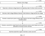
- the photovoltaic power generation system further includes a second controller connected to the direct current converter, and is configured to: generate a second drive signal based on a third voltage difference, and control, based on the second drive signal, the active power output by the direct current converter.
- the third voltage difference is a difference between a third reference voltage and the first voltage, and the third reference voltage is the rated voltage output by the direct current converter during normal operation of the power grid.
- a direct current controller may adjust the active power output by the direct current converter, so that the inverter can output the active power for implementing frequency support. In this way, the output active power meets a frequency support requirement.
- the second controller may directly determine the power grid frequency based on the first voltage, the power grid frequency does not need to be obtained through a high-speed transmission line. This increases a frequency support speed of the photovoltaic power generation system.
- the second controller is specifically configured to: determine an operating mode of the direct current converter, where the operating mode includes a unidirectional support mode and a bidirectional support mode; generate the third reference voltage based on the operating mode of the direct current converter and an operating parameter of the direct current converter, where the operating parameter of the direct current converter includes one or more of an input current, an input voltage, and an input power; obtain a fourth power based on the third voltage difference and a seventh droop coefficient, where the seventh droop coefficient is determined based on a correspondence between the output voltage of the direct current converter and the active power output by the direct current converter; determine a second active power control signal based on the fourth power and a maximum power; and generate the second drive signal based on the second active power control signal and an input parameter of the direct current converter.
- a current power grid status may be determined based on the second voltage difference between the voltage output by the direct current converter and the reference voltage, and corresponding power adjustment is performed, to implement frequency support.
- the second controller is further configured to calculate the maximum power MPPE based on the operating parameter of the direct current converter.
- the direct current converter operates in an MPPT mode without frequency support, and outputs the maximum power.
- the maximum power may be estimated based on the MPPE, and power adjustment is performed based on the maximum power.
- the second controller is specifically configured to: determine an additional reserved power based on the operating mode of the direct current converter; and generate the third reference voltage based on the operating parameter of the direct current converter and the additional reserved power.
- an output power of the direct current converter may be determined based on the operating parameter of the direct current converter and a specified additional reserved power, to dynamically adjust a reference voltage.
- an embodiment of this application provides a photovoltaic power generation system control method.
- the method may be applied to a photovoltaic power generation system, and specifically includes the following steps: monitoring an operating parameter of a power grid, a first voltage output by an inverter, and an active power output by a direct current converter; and generating a first drive signal based on two of the first voltage, the active power output by the direct current converter, and the operating parameter of the power grid, and controlling an operating state of the inverter based on the first drive signal, where the first voltage is a voltage amplitude of a direct current output by the direct current converter, and the operating parameter of the power grid includes one or more of a reactive current, an active current, a reactive power, an active power, a voltage amplitude, and a power grid frequency.
- the generating a first drive signal based on two of the first voltage, the active power output by the inverter, and the operating parameter of the power grid includes: generating a first active power control signal based on a first voltage difference and a first frequency difference, where the first voltage difference is a difference between the first voltage and a first reference voltage, the first frequency difference is a difference between the power grid frequency and a first reference frequency, the first reference voltage is a rated voltage output by the direct current converter during normal operation of the power grid, and the first reference frequency is a rated frequency during normal operation of the power grid; and generating the first drive signal based on the first active power control signal and the operating parameter of the power grid.
- the generating the first drive signal based on the first active power control signal and the operating parameter of the power grid includes: generating a first modulated wave signal based on the first active power control signal and the operating parameter of the power grid; and generating the first drive signal based on the first modulated wave signal and a first carrier signal, where the first carrier signal is a sine wave signal with a fixed period or a pulse signal.
- the generating a first active power control signal based on a first voltage difference and a first frequency difference includes: obtaining a first power based on the first voltage difference and a first droop coefficient, where the first droop coefficient is determined based on a correspondence between the direct current voltage output by the direct current converter and the active power output by the direct current converter; obtaining a second power based on the first frequency difference and a second droop coefficient, where the second droop coefficient is determined based on a correspondence between the power grid frequency and the active power output by the inverter; and generating the first active power control signal based on the first power, the second power, and a third power, where the third power is an initial active power delivered by a plant management system, and the plant management system is configured to control an operating state of the photovoltaic power generation system.
- the method further includes: obtaining the power grid frequency and the first voltage in a process of controlling the operating state of the inverter based on the first drive signal; and when it is determined that the power grid frequency obtained this time is the same as a power grid frequency obtained at an adjacent time and that the first voltage obtained this time is greater than a first voltage obtained last time, adjusting the first drive signal, to increase an active power output by the photovoltaic power generation system, where the active power output by the photovoltaic power generation system is less than or equal to a first specified value after the first drive signal is adjusted, and the first specified value is a maximum active power output by the photovoltaic power generation system during normal operation of the power grid.
- the method further includes: obtaining the power grid frequency and the first voltage in a process of controlling the operating state of the inverter based on the first drive signal; and when it is determined that the first voltage obtained this time is the same as a first voltage obtained at an adjacent time and that the power grid frequency obtained this time is greater than a power grid frequency obtained last time, adjusting the first drive signal, to reduce an active power output by the photovoltaic power generation system.
- the active power output by the photovoltaic power generation system is greater than or equal to a second specified value after the first drive signal is adjusted, and the second specified value is a minimum active power output by the photovoltaic power generation system during normal operation of the power grid.
- the generating a first drive signal based on two of the first voltage, the active power output by the inverter, and the operating parameter of the power grid includes: generating a first voltage control signal based on a first power difference and a second frequency difference, where the first power difference is a difference between the active power output by the inverter and a first reference power, the second frequency difference is a difference between the power grid frequency and a second reference frequency, the first reference power is a rated active power output by the inverter during normal operation of the power grid, and the first reference frequency is a rated frequency during normal operation of the power grid; and generating the first drive signal based on the first voltage control signal and the operating parameter of the power grid.
- the generating the first drive signal based on the first voltage control signal and the operating parameter of the power grid includes: generating a second modulated wave signal based on the first voltage control signal and the operating parameter of the power grid; and generating the first drive signal based on the second modulated wave signal and a second carrier signal, where the second carrier signal is a sine wave signal with a fixed period or a pulse signal.
- the generating a first voltage control signal based on a first power difference and a second frequency difference includes: obtaining a first direct current voltage based on the first power difference and a third droop coefficient, where the third droop coefficient is determined based on a correspondence between an active power output by the direct current converter and the direct current output by the direct current converter; obtaining a second direct current voltage based on the second frequency difference and a fourth droop coefficient, where the fourth droop coefficient is determined based on a correspondence between the power grid frequency and the direct current output by the direct current converter; and generating the first voltage control signal based on the first direct current voltage, the second direct current voltage, and a third direct current voltage, where the third direct current voltage is an initial direct current voltage delivered by a plant management system, and the plant management system is configured to control an operating state of the photovoltaic power generation system.
- the method further includes: in a process of controlling the operating state of the inverter based on the first drive signal, obtaining the power grid frequency and the active power output by the inverter; and when it is determined that the active power, output by the inverter, obtained this time is the same as an active power, output by the inverter, obtained at an adjacent time and that the power grid frequency obtained this time is greater than a power grid frequency obtained last time, adjusting the first drive signal, to increase the first voltage output by the direct current converter and reduce an active power output by the photovoltaic power generation system.
- the active power output by the photovoltaic power generation system is greater than or equal to a third specified value after the first drive signal is adjusted, and the third specified value is a minimum active power output by the photovoltaic power generation system during normal operation of the power grid.
- the method further includes: in a process of controlling the operating state of the inverter based on the first drive signal, obtaining the power grid frequency and the active power output by the inverter; and when it is determined that the power grid frequency obtained this time is the same as a power grid frequency obtained at an adjacent time and that the active power, output by the inverter, obtained this time is greater than an active power, output by the inverter, obtained last time, adjusting the first drive signal, to increase the first voltage output by the direct current converter and reduce an active power output by the photovoltaic power generation system.
- the active power output by the photovoltaic power generation system is greater than or equal to a fourth specified value after the first drive signal is adjusted, and the fourth specified value is a minimum active power output by the photovoltaic power generation system during normal operation of the power grid.
- the generating a first drive signal based on two of the first voltage, the active power output by the inverter, and the operating parameter of the power grid includes: generating a first frequency control signal based on a second power difference and a second voltage difference, where the second power difference is a difference between the active power output by the inverter and a second reference power, the second voltage difference is a difference between the first voltage and a second reference voltage, the second reference power is a rated active power output by the inverter during normal operation of the power grid, and the second reference voltage is a rated voltage output by the direct current converter during normal operation of the power grid; and generating the first drive signal based on the first frequency control signal and the operating parameter of the power grid.
- the generating the first drive signal based on the first frequency control signal and the operating parameter of the power grid includes: generating a third modulated wave signal based on the first frequency control signal and the operating parameter of the power grid; and generating the first drive signal based on the third modulated wave signal and a third carrier signal, where the third carrier signal is a sine wave signal with a fixed period or a pulse signal.
- the generating a first frequency control signal based on a second power difference and a second voltage difference includes: generating a first frequency based on the second power difference and a fifth droop coefficient, where the fifth droop coefficient is determined based on a correspondence between the active power output by the inverter and the power grid frequency; generating a second frequency based on the second voltage difference and a sixth droop coefficient, where the sixth droop coefficient is determined based on a correspondence between the direct current output by the direct current converter and the power grid frequency; and generating the first frequency control signal based on the first frequency, the second frequency, and a third frequency, where the third frequency is an initial frequency delivered by a plant management system, and the plant management system is configured to control an operating state of the photovoltaic power generation system.
- the method further includes: in a process of controlling the operating state of the inverter based on the first drive signal, obtaining the first voltage and the active power output by the inverter; and when it is determined that the active power, output by the inverter, obtained this time is the same as an active power, output by the inverter, obtained at an adjacent time and that the first voltage obtained this time is greater than a first voltage obtained last time, adjusting the first drive signal, to increase a frequency of an alternating current output by the inverter and increase an active power output by the photovoltaic power generation system.
- the active power output by the photovoltaic power generation system is less than or equal to a fifth specified value and the power grid frequency is less than or equal to a maximum frequency during normal operation of the power grid.
- the fifth specified value is a maximum active power output by the photovoltaic power generation system during normal operation of the power grid.
- the method further includes: in a process of controlling the operating state of the inverter based on the first drive signal, obtaining the first voltage and the active power output by the inverter; and when it is determined that the first voltage obtained this time is the same as a first voltage obtained at an adjacent time and that the active power, output by the inverter, obtained this time is greater than an active power, output by the inverter, obtained last time, adjusting the first drive signal, to reduce a frequency of an alternating current output by the inverter and reduce an active power output by the photovoltaic power generation system.
- the active power output by the photovoltaic power generation system is greater than or equal to a sixth specified value and the power grid frequency is greater than or equal to a minimum frequency during normal operation of the power grid.
- the sixth specified value is a minimum active power output by the photovoltaic power generation system during normal operation of the power grid.
- the method further includes: generating a second drive signal based on the first voltage and a third voltage difference, and controlling, based on the second drive signal, the active power output by the direct current converter, where the third voltage difference is a difference between a third reference voltage and the first voltage, and the third reference voltage is the rated voltage output by the direct current converter during normal operation of the power grid.
- the generating a second drive signal based on the first voltage and a third voltage difference includes: determining an operating mode of the direct current converter, where the operating mode includes a unidirectional support mode and a bidirectional support mode; generating the third reference voltage based on the operating mode of the direct current converter and an operating parameter of the direct current converter, where the operating parameter of the direct current converter includes one or both of an input current and an input power; obtaining a fourth power based on the third voltage difference and a seventh droop coefficient, where the seventh droop coefficient is determined based on a correspondence between the output voltage of the direct current converter and the active power output by the direct current converter; determining a second active power control signal based on the fourth power and a maximum power MPPE; and generating the second drive signal based on the second active power control signal and an input parameter of the direct current converter.
- the generating the second drive signal based on the second active power control signal and an input parameter of the direct current converter includes: generating a fourth modulated wave signal based on the second active power control signal and the input parameter of the direct current converter; and generating the second drive signal based on the fourth modulated wave signal and a fourth carrier signal, where the fourth carrier signal is a sine wave signal with a fixed period or a pulse signal.
- the method further includes: determining the MPPE based on the operating parameter of the direct current converter.
- the generating the third reference voltage based on the operating mode of the direct current converter and an operating parameter of the direct current converter includes: determining an additional reserved power based on the operating mode of the direct current converter; and generating the third reference voltage based on the operating parameter of the direct current converter and the additional reserved power.
- the solutions disclosed in this application may be applied to a new energy system, and applied to a grid-connected scenario of the new energy system.
- the new energy system includes but is not limited to a photovoltaic power generation system, a wind power generation system, a water power generation system, or the like.
- the new energy system may be a photovoltaic power generation system.
- FIG. 1 is an example of a schematic diagram of a structure of a photovoltaic power generation system. Refer to FIG. 1 .
- the photovoltaic power generation system mainly includes a direct current converter, an inverter, and a controller.
- the photovoltaic power generation system is connected to a photovoltaic module, and outputs electric energy output by the photovoltaic module to a power grid.
- the photovoltaic power generation system includes the photovoltaic module.
- the photovoltaic module may convert light energy into a direct current.
- the direct current converter is connected to an output end of the photovoltaic module, and may receive the direct current output by the photovoltaic module and perform voltage conversion on the received direct current.
- the inverter may receive a direct current that is output by the direct current converter and that is obtained through voltage conversion, convert the received direct current into an alternating current, and output the alternating current to the power grid through a grid connection point, thereby implementing grid connection of the photovoltaic power generation system.
- the controller is connected to the inverter, and is configured to control the inverter to convert the received direct current into an alternating current.
- the direct current converter is usually connected to the inverter through a direct current bus, in other words, a voltage amplitude of the direct current output by the direct current converter is a direct current bus voltage.
- the inverter includes a plurality of switch devices.
- the controller sends a drive signal to the plurality of switches in the inverter, to control conduction states of the plurality of switch devices in the inverter, so as to control operation of the inverter.
- the controller is connected to an upper-layer plant management system of the photovoltaic power generation system, and adjusts an operating state of the inverter when receiving a control instruction sent by the plant management system.
- the plant management system may obtain an operating parameter of the power grid periodically or in real time, and monitor an operating state of the power grid.
- the plant management system may calculate, based on an operating status of the power grid, an active power required for frequency support, and deliver a scheduling instruction to the controller.
- the controller adjusts a drive signal of a switching transistor in the inverter, to adjust an active power output by the inverter, so as to implement a frequency support function for the power grid.
- the frequency support function of the controller is implemented based on the scheduling instruction delivered by the upper-layer plant management system.
- the controller is controlled by the plant management system.
- a response speed is slow.
- embodiments of this application provide a photovoltaic power generation system and a photovoltaic power generation system control method, to quickly implement frequency support.
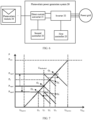
- FIG. 2 is a schematic diagram of a structure of a photovoltaic power generation system according to an embodiment of this application.
- the photovoltaic power generation system 20 includes a direct current converter 21, an inverter 22, and a first controller 23.
- An input end of the direct current converter 21 is connected to an output end of a photovoltaic module 24, an output end of the direct current converter 21 is connected to the inverter 22, and the inverter 22 is connected to the first controller 23.
- the photovoltaic power generation system 20 may further include the photovoltaic module 24.
- the photovoltaic module 24 may convert light energy into a direct current, and output the direct current to the direct current converter 21.
- the direct current converter 21 may perform voltage conversion on the direct current output by the photovoltaic module 24, and output a direct current obtained through voltage conversion.
- the inverter 22 may convert the direct current output by the direct current converter 21 into an alternating current and output the alternating current to a power grid, thereby implementing grid connection of the photovoltaic power generation system.
- the first controller 23 is connected to the inverter 22, and may control the inverter 22 to convert a received direct current into an alternating current.
- the direct current converter 21 is connected to the inverter 22 through a direct current bus.
- the direct current converter 21 is connected to the inverter 22 through the direct current bus, and a voltage of an alternating current output by the direct current converter 21 is a direct current bus voltage.
- the first controller 23 may generate a first drive signal based on two of a first voltage of the direct current output by the direct current converter 21, an active power output by the inverter 22, and an operating parameter of the power grid, and control an operating state of the inverter 22 based on the first drive signal, so that the alternating current output by the inverter 22 can implement a frequency support function.
- the first controller may generate an adjustment value of the other parameter based on any two of the foregoing three parameters, and generate a corresponding drive signal, so that the inverter 22 outputs the alternating current for implementing frequency support, to implement the frequency support function of the photovoltaic power generation system.
- the operating parameter of the power grid may include one or more of the following: a reactive current, an active current, an active power, a reactive power, a voltage amplitude, and a power grid frequency.
- the local first controller 23 of the photovoltaic power generation system 20 may perform frequency support calculation.
- the photovoltaic power generation system reduces a time for obtaining the power grid frequency and a related parameter and a time for delivering a scheduling instruction, thereby implementing fast frequency support, and quickly restoring the power grid to a stable state.
- the first voltage that represents an electric energy generation status of the photovoltaic power generation system 20 participates in frequency support calculation. Because the electric energy generation status of the photovoltaic power generation system 20 is considered, an active power output by the photovoltaic power generation system 20 may be appropriately increased without affecting operation of the power grid, to increase a proportion of new energy in the power grid.
- the inverter 22 may include devices such as a switching transistor, a diode, an inductor, and a capacitor.
- the operating state of the inverter 22 may be implemented by adjusting operating states of these devices (for example, switching transistors).
- the first controller 23 may be connected to a gate of the MOS transistor, to adjust an operating status of the inverter 22 by controlling on/off of the MOS transistor; or if the switching transistor in the inverter 22 is a BJT, the first controller 23 may be connected to a base of the BJT, to adjust the operating status of the inverter 22 by controlling on/off of the BJT.
- the first controller 23 generates a first drive signal based on a first voltage output by the direct current converter 21 and a power grid frequency.
- the first controller 23 may calculate a first voltage difference between the first voltage and a first reference voltage, and calculate a first frequency difference between the power grid frequency and a first reference frequency; generate a first active power control signal based on the first voltage difference and the first frequency difference; and generate the first drive signal based on the first active power control signal and a current operating parameter of a power grid.
- the first reference voltage is a rated voltage output by the direct current converter 21 during normal operation of the power grid.
- the first reference frequency is a rated frequency during normal operation of the power grid.
- the power grid frequency when the power grid frequency is higher than the first reference frequency, it indicates that an active power currently transmitted on the power grid is higher than an active power actually required by the power grid.
- the power grid frequency is lower than the first reference frequency, it indicates that an active power currently transmitted on the power grid is lower than an active power actually required by the power grid; and an active power-frequency droop control policy is established based on a correspondence between the power grid frequency and an active power output by an inverter.
- the direct current converter 21 when the first voltage output by the direct current converter 21 is higher than the first reference voltage, it indicates that a power output by the direct current converter 21 exceeds a rated power during normal operation of the power grid; when the inverter sends the power to the power grid, the power transmitted on the power grid exceeds the power actually required by the power grid.
- the direct current converter 21 When the first voltage output by the direct current converter 21 is lower than the first reference power, it indicates that the power output by the direct current converter 21 exceeds the rated power during normal operation of the power grid; and when the inverter sends the power to the power grid, the power transmitted on the power grid is less than the power actually required by the power grid, and a voltage-active power droop control policy is established based on a correspondence between the active power output by the inverter and a direct current bus voltage. An active power required for frequency support is obtained through calculation according to the foregoing two droop control policies.
- the first controller 23 forms the voltage-active power droop control policy based on the first voltage difference and a first droop coefficient, to obtain a first power; and the first controller 23 obtains a second power based on the first frequency difference and a second droop coefficient, where the second droop coefficient is determined based on the correspondence between the power grid frequency and the active power output by the inverter.
- the first active power control signal required for frequency support is generated based on the first power and the second power that are obtained according to the foregoing two droop control policies, and a third power.
- the first droop coefficient is determined based on a correspondence between a direct current output by the direct current converter and the active power output by the inverter.
- the third power is an initial active power delivered by a plant management system, and the plant management system is configured to control an operating state of the photovoltaic power generation system 20.
- the first controller 23 may be separately connected to a direct current sensor and an alternating current sensor.
- the direct current sensor is configured to detect the first voltage output by the direct current converter 21, and the alternating current sensor may detect the operating parameter of the power grid.
- An alternating current detection unit may be, but is not limited to, a voltage sensor and a current sensor, for example, a Hall effect sensor.
- K up indicates the first droop coefficient
- K pf indicates the second droop coefficient
- U bus indicates the first voltage
- U InvBus ref indicates the first reference voltage
- f req indicates the power grid frequency
- f req ref indicates the first reference frequency
- P cmd indicates the initial active power delivered by the upper-layer plant management system.
- the first droop coefficient K up and the second droop coefficient K pf may be, but are not limited to, constants, exponents, and power exponents.
- the first droop coefficient is set based on a curve of the correspondence between the direct current bus voltage and the active power output by the inverter 22, and the second droop coefficient is set based on a curve of the correspondence between the active power output by the inverter and the power grid frequency.
- the foregoing values may be configured by using a proportional controller, an integrator, another combination, or a user selection.
- the first controller 23 generates the first active power control signal according to the foregoing formula 1, and generates a first modulated wave signal based on the first active power control signal and the current operating parameter of the power grid. After the first modulated wave signal is compared with a first carrier signal, the first drive signal is generated, and is sent to switching transistors in the inverter 22. The switching transistors in the inverter 22 adjust a conduction time sequence of the switching transistors under control of the first drive signal, to adjust the active power output by the inverter 22, so as to implement a frequency support function.
- the first carrier signal may be a sine wave signal with a fixed period or a pulse signal.
- the active power output by the inverter 22 may be dynamically adjusted based on a dynamic change of the direct current bus voltage and a dynamic change of the power grid frequency.
- the first controller 23 adjusts, according to both the voltage-active power droop control policy and the active power-frequency droop control policy, the active power output by the inverter 22. It can be learned from the foregoing formula 1 that, when the power grid frequency remains unchanged, because the direct current converter 21 operates in an MPPT mode, as the direct current bus voltage gradually increases within a range of [Ubusmin, Ubusmax], it indicates that when an electric energy yield of the photovoltaic power generation system 20 gradually increases, the active power output by the inverter 22 may be controlled without affecting operation of the power grid, to increase monotonically.
- the range of the direct current bus voltage is an operating range of the direct current bus during normal operation of the direct current converter 21, and is determined based on an operating voltage of the direct current converter 21 and an alternating current voltage amplitude at an output side of the inverter.
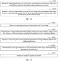
- the first controller may periodically obtain the power grid frequency and the first voltage in a process of controlling an operating state of the inverter based on the first drive signal; and when it is determined that the power grid frequency obtained this time is the same as a power grid frequency obtained at an adjacent time and that the first voltage obtained this time is greater than a first voltage obtained last time, adjust the first drive signal, to increase an active power output by the photovoltaic power generation system.
- the active power output by the photovoltaic power generation system is less than or equal to a first specified value after the first drive signal is adjusted, and the first specified value is a maximum active power output by the photovoltaic power generation system during normal operation of the power grid.
- the first specified value may be configured based on an electric energy device connected to the power grid.
- the power grid frequency increases, and another device on the power grid may reduce an amount of electric energy transmitted to the power grid, to implement coordinated control with the another device on the power grid.
- the first controller 23 adjusts, according to both the voltage-active power droop control policy and the active power-frequency droop control policy, the active power output by the inverter 22. It can be learned from the formula 1 that, when the direct current bus voltage remains unchanged, as the power grid frequency gradually increases within a range of [freqmin, freqmax], it indicates that when an active power currently transmitted on the power grid gradually increases and exceeds the active power actually required by the power grid, the active power output by the inverter 22 may be controlled to decrease monotonically. For the correspondence between the active power output by the inverter 22 and the power grid frequency, refer to FIG. 4 .
- the range of the power grid frequency is a fluctuation range during normal operation of the power grid.
- the first controller may periodically obtain the power grid frequency and the first voltage in a process of controlling an operating state of the inverter based on the first drive signal; and adjust the first drive signal when it is determined that the first voltage obtained this time is the same as a first voltage obtained at an adjacent time and that the power grid frequency obtained this time is greater than a power grid frequency obtained last time, to reduce an active power output by the photovoltaic power generation system.
- the active power output by the photovoltaic power generation system is greater than or equal to a second specified value after the first drive signal is adjusted, and the second specified value is a minimum active power output by the photovoltaic power generation system during normal operation of the power grid.
- FIG. 5 It can be learned from FIG. 3, FIG. 4 , and content of the formula 1 that, when the active power output by the inverter 22 is fixed, for a correspondence between the direct current bus voltage and the power grid frequency, refer to FIG. 5 .
- the first controller 23 generates a first drive signal based on an active power output by the inverter 22 and a power grid frequency.
- the first controller 23 may generate a first voltage control signal based on a first power difference and a second frequency difference, and generate the first drive signal based on the first voltage control signal and an operating parameter of a power grid.
- the first power difference is a difference between the active power output by the inverter 22 and a first reference power
- the second frequency difference is a difference between the power grid frequency and a second reference frequency
- the first reference power is a rated active power output by the inverter 22 during normal operation of the power grid
- the first reference frequency is a rated frequency during normal operation of the power grid.
- the power grid frequency when the power grid frequency is higher than the second reference frequency, it indicates that an active power currently transmitted on the power grid is higher than an active power actually required by the power grid.
- the power grid frequency is lower than the second reference frequency, it indicates that an active power currently transmitted on the power grid is lower than an active power actually required by the power grid, and an active power-frequency droop control policy is established based on a correspondence between the power grid frequency and the active power.
- a direct current bus voltage increases; or when the power grid frequency is lower than a first reference frequency, a direct current bus voltage decreases.
- a voltage-frequency droop control policy is established based on a correspondence between the power grid frequency and the direct current bus voltage.
- a first voltage for frequency support is calculated according to the foregoing two droop control policies.
- the first controller 23 obtains a first direct current voltage based on the first power difference and a third droop coefficient, where the third droop coefficient is determined based on a correspondence between an active power output by the direct current converter 21 and a direct current output by the direct current converter 21; obtains a second direct current voltage based on the second frequency difference and a fourth droop coefficient, where the fourth droop coefficient is determined based on a correspondence between the power grid frequency and the direct current output by the direct current converter; and generates the first voltage control signal based on the first direct current voltage, the second direct current voltage, and a third direct current voltage.
- the third direct current voltage is an initial direct current voltage delivered by a plant management system, and the plant management system is configured to control an operating state of a photovoltaic power generation system.
- the inverter 22 may operate in an MPPT mode.
- the inverter 22 may control an output power of the direct current converter by adjusting the output voltage of the direct current converter.
- an input voltage of the inverter 22 changes, a voltage output by the inverter to the power grid also changes, to implement frequency support.
- the first controller 23 may be separately connected to a first sensor and a second sensor.
- the first sensor is configured to detect the operating parameter of the power grid
- the second sensor is configured to detect the active power output by the inverter 22.
- the first sensor and the second sensor each are an alternating current sensor, for example, a Hall effect sensor.
- the third droop coefficient is determined based on the correspondence between the active power output by the direct current converter 21 and the direct current output by the direct current converter
- the fourth droop coefficient is determined based on the correspondence between the power grid frequency and the direct current output by the direct current converter 21.
- the third droop coefficient is set based on a curve of a correspondence between the direct current bus voltage and the active power output by the inverter 22, and the fourth droop coefficient is set based on a curve of a correspondence between the first voltage output by the direct current converter 21 and the power grid frequency.
- the foregoing values may be configured by using a proportional controller, an integrator, another combination, or a user selection.
- the first controller 23 generates, according to the foregoing formula 2, the first voltage control signal for implementing frequency support, and generates a second modulated wave signal based on the first voltage control signal and a current operating parameter of the power grid. After the second modulated wave signal is compared with a second carrier signal, the first drive signal is generated, and is sent to switching transistors in the inverter 22. The switching transistors in the inverter 22 adjust a conduction time sequence of the switching transistors under control of the second drive signal, to adjust the active power output by the inverter 22, so as to implement a frequency support function.
- the second carrier signal may be a sine wave signal with a fixed period or a pulse signal.
- a direct current voltage output by the direct current converter 21 may be dynamically adjusted based on a dynamic change of the power grid frequency and a dynamic change of the active power output by the inverter.
- the first controller 23 adjusts, according to both the voltage-active power droop control policy and the voltage-frequency droop control policy, the direct current voltage received by the inverter 22. It can be learned from the formula 2 that, when the active power output by the inverter 22 remains unchanged, as the power grid frequency gradually increases within a range of [freqmin, freqmax], it indicates that the active power currently transmitted on the power grid gradually increases and exceeds the active power actually required by the power grid. A first voltage amplitude output by the direct current converter 21 may be increased, to reduce the active power output by the inverter 22, so as to ensure normal operation of the power grid.
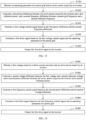
- the first controller may periodically obtain, based on the first drive signal in a process of controlling an operating state of the inverter, the power grid frequency and the active power output by the inverter; and when it is determined that the active power, output by the inverter, obtained this time is the same as an active power, output by the inverter, obtained at an adjacent time and that the power grid frequency obtained this time is greater than a power grid frequency obtained last time, adjust the first drive signal, to increase the first voltage output by the direct current converter and reduce the active power output by the photovoltaic power generation system.
- the active power output by the photovoltaic power generation system is greater than or equal to a third specified value after the first drive signal is adjusted, and the third specified value is a minimum active power output by the photovoltaic power generation system during normal operation of the power grid.
- the first controller may periodically obtain, in a process of controlling an operating state of the inverter based on the first drive signal, the power grid frequency and the active power output by the inverter; and when it is determined that the power grid frequency obtained this time is the same as a power grid frequency obtained at an adjacent time and that the active power, output by the inverter, obtained this time is greater than an active power, output by the inverter, obtained last time, adjust the first drive signal, to increase the first voltage output by the direct current converter and reduce an active power output by the photovoltaic power generation system.
- the active power output by the photovoltaic power generation system is greater than or equal to a fourth specified value after the first drive signal is adjusted, and the fourth specified value is a minimum active power output by the photovoltaic power generation system during normal operation of the power grid.
- the first controller 23 may generate a first drive signal based on a first voltage of a direct current output by the direct current converter 21 and an active power output by the inverter 22.
- the first controller 23 generates a first frequency control signal based on a second power difference and a second voltage difference, and generates the first drive signal based on the first frequency control signal and an operating parameter of a power grid.
- the second power difference is a difference between the active power output by the inverter and a second reference power
- the second voltage difference is a difference between the first voltage and a second reference voltage
- the second reference power is a rated active power output by the inverter during normal operation of the power grid
- the second reference voltage is a rated voltage output by the direct current converter during normal operation of the power grid.
- the active power output by the inverter 22 when the active power output by the inverter 22 is higher than the second reference power, it indicates that the active power output by the inverter 22 is higher than an active power actually required by the power grid, resulting in an increase of a power grid frequency.
- the active power output by the inverter 22 is lower than the second reference power, it indicates that the active power output by the inverter 22 is lower than an active power actually required by the power grid, resulting in a decrease of a power grid frequency.
- An active power-frequency droop control policy is established based on a correspondence between the active power output by the inverter 22 and the power grid frequency.
- a voltage-frequency droop control policy is established based on a correspondence between the first voltage output by the direct current converter 21 and the power grid frequency, and a frequency for frequency support is calculated according to the foregoing two droop control policies.
- the first controller 23 obtains a first direct current voltage based on a first power difference and a third droop coefficient, where the third droop coefficient is determined based on a correspondence between an active power output by the direct current converter and the direct current output by the direct current converter; obtains a second direct current voltage based on a second frequency difference and a fourth droop coefficient, where the fourth droop coefficient is determined based on a correspondence between the power grid frequency and the direct current output by the direct current converter; and generates a first voltage control signal based on the first direct current voltage, the second direct current voltage, and a third direct current voltage.
- the third direct current voltage is an initial direct current voltage delivered by a plant management system, and the plant management system is configured to control an operating state of a photovoltaic power generation system.
- the first controller 23 may be separately connected to a direct current sensor and an alternating current sensor.
- the direct current sensor is configured to detect the first voltage output by the direct current converter 21, and the alternating current sensor is configured to detect the active power output by the inverter 22.
- the first controller 23 dynamically adjusts, based on a dynamic change of the active power output by the inverter 22 and a dynamic change of the first voltage output by the direct current converter 21, a frequency of an alternating current output by the inverter 22.
- the fifth droop coefficient is determined based on the correspondence between the active power output by the inverter and the power grid frequency
- the sixth droop coefficient is determined based on the correspondence between the direct current output by the direct current converter and the power grid frequency.
- the foregoing values may be configured by using a proportional controller, an integrator, another combination, or a user selection.
- the first controller 23 generates, according to the foregoing formula 3, the first frequency control signal for implementing frequency support, and generates a third modulated wave signal based on the first frequency control signal and a current operating parameter of the power grid. After the third modulated wave signal is compared with a third carrier signal, the first drive signal is generated, and is sent to switching transistors in the inverter 22. The switching transistors in the inverter 22 adjust a conduction time sequence of the switching transistors under control of the second drive signal, to adjust the active power output by the inverter 22, so as to implement a frequency support function.
- the third carrier signal may be a sine wave signal with a fixed period or a pulse signal.
- the frequency of the alternating current output by the inverter may be dynamically changed based on a dynamic change of the first voltage output by the direct current converter and a dynamic change of the active power output by the inverter.
- the first controller 23 adjusts, according to both the active power-frequency droop control policy and the voltage-frequency droop control policy, a direct current voltage received by the inverter 22. It can be learned from the formula 3 that, when the active power output by the inverter 22 remains unchanged, because the direct current converter 21 operates in an MPPT mode, and as a direct current bus voltage gradually increases within a range of [Ubusmin, Ubusmax], it indicates that when an electric energy yield of the photovoltaic power generation system 20 gradually increases, the active power output by the inverter 22 may be controlled without affecting operation of the power grid, to increase monotonically, the frequency of the alternating current output by the inverter increases, and the corresponding power grid frequency also increases.
- the first controller may periodically obtain, in a process of controlling an operating state of the inverter based on the first drive signal, the first voltage and the active power output by the inverter; and when it is determined that the active power, output by the inverter, obtained this time is the same as an active power, output by the inverter, obtained at an adjacent time and that the first voltage obtained this time is greater than a first voltage obtained last time, adjust the first drive signal, to increase the frequency of the alternating current output by the inverter and increase an active power output by the photovoltaic power generation system.
- the active power output by the photovoltaic power generation system is less than or equal to a fifth specified value and the power grid frequency is less than or equal to a maximum frequency during normal operation of the power grid.
- the fifth specified value is a maximum active power output by the photovoltaic power generation system during normal operation of the power grid.
- the active power output by the inverter 22 may be controlled to decrease monotonically, and the frequency of the alternating current output by the inverter 22 may be reduced, to reduce the power grid frequency, so as to ensure normal operation of the power grid.
- the first controller may periodically obtain the first voltage and the active power output by the inverter in a process of controlling an operating state of the inverter based on the first drive signal; and when it is determined that the first voltage obtained this time is the same as a first voltage obtained at an adjacent time and that the active power, output by the inverter, obtained this time is greater than an active power, output by the inverter, obtained last time, adjust the first drive signal, to reduce the frequency of the alternating current output by the inverter and reduce the active power output by the photovoltaic power generation system.
- the active power output by the photovoltaic power generation system is greater than or equal to a sixth specified value and the power grid frequency is greater than or equal to a minimum frequency during normal operation of the power grid.
- the sixth specified value is a minimum active power output by the photovoltaic power generation system during normal operation of the power grid.
- the first specified value and the fifth specified value may be a same value
- the second specified value, the third specified value, the fourth specified value, and the sixth specified value may be a same value.
- the active power output by the inverter may be separately controlled according to the foregoing formula 1, or the direct current voltage and the frequency may be controlled according to the foregoing formula 2 and the foregoing formula 3, to implement composite control.
- the inverter 22 is connected to the direct current converter 21, and the active power output by the inverter 22 is mainly obtained from the direct current converter 21.
- the photovoltaic power generation system 20 may further include a second controller. Refer to FIG. 6 .
- the second controller 25 may be connected to the direct current converter 21, and may generate a second drive signal based on a third voltage difference between a third reference voltage and the first voltage, and control, based on the second drive signal, the active power output by the direct current converter 21.
- the third reference voltage is a rated voltage output by the direct current converter 21 during normal operation of the power grid.
- the second controller 25 may determine a current power grid frequency by detecting the direct current bus voltage, to output the active power for frequency support to the inverter 22.
- the second controller 25 may directly adjust, based on the correspondence between the power grid frequency and the direct current bus voltage, the active power by detecting a current direct current bus voltage, so that a frequency at a power grid side does not need to be obtained through a high-speed transmission line, and a problem that frequency support of the direct current converter 21 is limited by frequency sampling performance and high-speed communication performance can be resolved.
- the direct current converter 21 may control the direct current bus voltage, to indicate an electric energy generation status of the photovoltaic power generation system by using the inverter, so that the inverter can control, based on the electric energy generation status, an active power output to the power grid, and notify, through a change of the power grid frequency, another device connected to the power grid.
- the second controller is specifically configured to: determine an operating mode of the direct current converter, where the operating mode includes a unidirectional support mode and a bidirectional support mode; generate the third reference voltage based on the operating mode of the direct current converter and an operating parameter of the direct current converter, where the operating parameter of the direct current converter includes one or more of an input current, an input voltage, and an input power; obtain a fourth power based on the third voltage difference and a seventh droop coefficient, where the seventh droop coefficient is determined based on a correspondence between the output voltage of the direct current converter and the active power output by the direct current converter; determine a second active power control signal based on the fourth power and a maximum power MPPE; and generate the second drive signal based on the second active power control signal and an input parameter of the direct current converter.
- the second controller may further include a direct current detection unit, configured to detect the direct current bus voltage to obtain the first voltage, and output the first voltage to a second droop calculation unit.
- the second controller 25 is connected to the direct current sensor, a signal input end of the direct current sensor is connected to an output end of the direct current converter, a signal output end of the direct current sensor is connected to the second controller 25, and the second controller 25 obtains the first voltage by using the direct current sensor.
- P BST indicates the generated second active power control signal
- P MPPE indicates the estimated maximum power
- D PV indicates the seventh droop coefficient.
- the seventh droop coefficient D PV may be, but is not limited to, a constant, an exponent, and a power exponent.
- U BstBusRef indicates a specified value
- dU(P, U bus , ⁇ P) indicates a dynamic voltage adjustment value
- P indicates the maximum power output by the inverter
- ⁇ P indicates a specified additional reserved power.
- the dynamic voltage adjustment value may be obtained by using a proportional controller, an integrator, or another combination.
- the direct current converter 24 connected to the photovoltaic module 24 dynamically adjusts a voltage of the direct current converter, to operate in the MPPT mode.
- ⁇ P is zero.
- ⁇ P is less than the maximum power and greater than zero, for example, ⁇ P may be 10% of the maximum power, and then another value may be selected, for example, 15% of the maximum power.
- ⁇ P is set, to control the direct current converter to operate at a reduced power, so as to implement bidirectional support for the power grid frequency.
- the bus reference voltage of the direct current converter is mainly determined based on a dynamic voltage point, in other words, the direct current converter 21 has a unidirectional support capability of quickly reducing the power, but does not have a support capability of quickly increasing the power.
- the direct current converter can operate in the MPPT mode during normal operation of the power grid, to ensure the electric energy yield of the photovoltaic power generation system.
- the direct current converter 21 outputs a maximum power Pmppt1 at an operation point O1, and has a fast unidirectional power support capability.
- an output power of an MPPT unit is increased.
- the MPPT unit moves the dynamic point of the direct current converter 21 to a maximum power point O2, in other words, a mode selection module updates a reference value U BstBus ref of a direct current voltage droop to a point U2, so that the direct current converter operates in the MPPT mode, and has a fast unidirectional power support capability.
- an operating voltage of the direct current converter is reduced to a maximum power point O3 through calculation according to the formula 2 and the formula 3, so that the direct current converter operates in the MPPT mode, and has a fast unidirectional power support capability.
- Selection of the operating mode of the direct current converter may be set based on a user selection or may be set by receiving a selection instruction delivered by an upper layer. Certainly, the selection of the operating mode may be alternatively set in another manner. For example, a default operating mode is set for the direct current converter. When the photovoltaic power generation system is grid-connected, operation of the direct current converter may be controlled in the default operating mode.
- this application is applicable to grid-connected architectures of other new energy systems, for example, a wind power generation system and a water power generation system, where the new energy systems each are an application scenario in which a grid-connected inverter is disposed to perform grid connection based on generated electric energy; and is also applicable to a large-scale energy storage application scenario, a small/medium-scale distributed energy storage application scenario, and the like.
- This is merely an example for description, and a specific application scenario is not limited in this application.
- this application is also applicable to an off-grid scenario of the new energy system.
- an embodiment of this application further provides a photovoltaic power generation system control method, applied to a photovoltaic power generation system.
- the method may be performed by a controller in the photovoltaic power generation system.
- the controller in the photovoltaic power generation system includes a first controller connected to an inverter.
- the method provided in this embodiment of this application specifically includes the following steps.
- Step 1301 Monitor an operating parameter of a power grid, a first voltage of a direct current output by a direct current converter, and an active power output by the inverter.
- the first voltage is a voltage amplitude of the direct current output by the direct current converter
- the operating parameter of the power grid includes one or more of a reactive current, an active current, a reactive power, an active power, a voltage amplitude, and a power grid frequency.
- the operating parameter of the power grid, the first voltage, and the active power output by the inverter may be obtained by using a corresponding alternating current sensor or direct current sensor, for example, a voltage sensor or a current sensor.
- Step 1302 Generate a first drive signal based on two of the first voltage, the active power output by the inverter, and the operating parameter of the power grid, and control an operating state of the inverter based on the first drive signal.
- the generating a first drive signal based on two of the first voltage, the active power output by the inverter, and the operating parameter of the power grid includes: generating a first active power control signal based on a first voltage difference and a first frequency difference, where the first voltage difference is a difference between the first voltage and a first reference voltage, the first frequency difference is a difference between the power grid frequency and a first reference frequency, the first reference voltage is a rated voltage output by the direct current converter during normal operation of the power grid, and the first reference frequency is a rated frequency during normal operation of the power grid; and generating the first drive signal based on the first active power control signal and the operating parameter of the power grid.
- the generating the first drive signal based on the first active power control signal and the operating parameter of the power grid includes: generating a first modulated wave signal based on the first active power control signal and the operating parameter of the power grid; and generating the first drive signal based on the first modulated wave signal and a first carrier signal, where the first carrier signal is a sine wave signal with a fixed period or a pulse signal.
- the generating a first active power control signal based on a first voltage difference and a first frequency difference includes: obtaining the first power based on the first voltage difference and a first droop coefficient, where the first droop coefficient is determined based on a correspondence between the direct current voltage output by the direct current converter and the active power output by the direct current converter; obtaining a second power based on the first frequency difference and a second droop coefficient, where the second droop coefficient is determined based on a correspondence between the power grid frequency and the active power output by the inverter; and generating the first active power control signal based on the first power, the second power, and a third power, where the third power is an initial active power delivered by a plant management system, and the plant management system is configured to control an operating state of the photovoltaic power generation system.
- control method further includes: obtaining the power grid frequency and the first voltage in a process of controlling the operating state of the inverter based on the first drive signal; and when it is determined that the power grid frequency obtained this time is the same as a power grid frequency obtained at an adjacent time and that the first voltage obtained this time is greater than a first voltage obtained last time, adjusting the first drive signal, to increase an active power output by the photovoltaic power generation system, where the active power output by the photovoltaic power generation system is less than or equal to a first specified value after the first drive signal is adjusted, and the first specified value is a maximum active power output by the photovoltaic power generation system during normal operation of the power grid.
- control method further includes: obtaining the power grid frequency and the first voltage in a process of controlling the operating state of the inverter based on the first drive signal; and when it is determined that the first voltage obtained this time is the same as a first voltage obtained at an adjacent time and that the power grid frequency obtained this time is greater than a power grid frequency obtained last time, adjusting the first drive signal, to reduce an active power output by the photovoltaic power generation system, where the active power output by the photovoltaic power generation system is greater than or equal to a second specified value after the first drive signal is adjusted, and the second specified value is a minimum active power output by the photovoltaic power generation system during normal operation of the power grid.
- the generating a first drive signal based on two of the first voltage, the active power output by the inverter, and the operating parameter of the power grid includes: generating a first voltage control signal based on a first power difference and a second frequency difference, where the first power difference is a difference between the active power output by the inverter and a first reference power, the second frequency difference is a difference between the power grid frequency and a second reference frequency, the first reference power is a rated active power output by the inverter during normal operation of the power grid, and the first reference frequency is a rated frequency during normal operation of the power grid; and generating the first drive signal based on the first voltage control signal and the operating parameter of the power grid.
- the generating the first drive signal based on the first voltage control signal and the operating parameter of the power grid includes: generating a second modulated wave signal based on the first voltage control signal and the operating parameter of the power grid; and generating the first drive signal based on the second modulated wave signal and a second carrier signal, where the second carrier signal is a sine wave signal with a fixed period or a pulse signal.
- the generating a first voltage control signal based on a first power difference and a second frequency difference includes: obtaining a first direct current voltage based on the first power difference and a third droop coefficient, where the third droop coefficient is determined based on a correspondence between an active power output by the direct current converter and the direct current output by the direct current converter; obtaining a second direct current voltage based on the second frequency difference and a fourth droop coefficient, where the fourth droop coefficient is determined based on a correspondence between the power grid frequency and the direct current output by the direct current converter; and generating the first voltage control signal based on the first direct current voltage, the second direct current voltage, and a third direct current voltage, where the third direct current voltage is an initial direct current voltage delivered by a plant management system, and the plant management system is configured to control an operating state of the photovoltaic power generation system.
- control method further includes: in a process of controlling the operating state of the inverter based on the first drive signal, obtaining the power grid frequency and the active power output by the inverter; and when it is determined that the active power, output by the inverter, obtained this time is the same as an active power, output by the inverter, obtained at an adjacent time and that the power grid frequency obtained this time is greater than a power grid frequency obtained last time, adjusting the first drive signal, to increase the first voltage output by the direct current converter and reduce an active power output by the photovoltaic power generation system.
- the active power output by the photovoltaic power generation system is greater than or equal to a third specified value after the first drive signal is adjusted, and the third specified value is a minimum active power output by the photovoltaic power generation system during normal operation of the power grid.
- control method further includes: in a process of controlling the operating state of the inverter based on the first drive signal, obtaining the power grid frequency and the active power output by the inverter; and when it is determined that the power grid frequency obtained this time is the same as a power grid frequency obtained at an adjacent time and that the active power, output by the inverter, obtained this time is greater than an active power, output by the inverter, obtained last time, adjusting the first drive signal, to increase the first voltage output by the direct current converter and reduce an active power output by the photovoltaic power generation system.
- the active power output by the photovoltaic power generation system is greater than or equal to a fourth specified value after the first drive signal is adjusted, and the fourth specified value is a minimum active power output by the photovoltaic power generation system during normal operation of the power grid.
- the generating a first drive signal based on two of the first voltage, the active power output by the inverter, and the operating parameter of the power grid includes: generating a first frequency control signal based on a second power difference and a second voltage difference, where the second power difference is a difference between the active power output by the inverter and a second reference power, the second voltage difference is a difference between the first voltage and a second reference voltage, the second reference power is a rated active power output by the inverter during normal operation of the power grid, and the second reference voltage is a rated voltage output by the direct current converter during normal operation of the power grid; and generating the first drive signal based on the first frequency control signal and the operating parameter of the power grid.
- the generating the first drive signal based on the first frequency control signal and the operating parameter of the power grid includes: generating a third modulated wave signal based on the first frequency control signal and the operating parameter of the power grid; and generating the first drive signal based on the third modulated wave signal and a third carrier signal, where the third carrier signal is a sine wave signal with a fixed period or a pulse signal.
- the generating a first frequency control signal based on a second power difference and a second voltage difference includes: generating a first frequency based on the second power difference and a fifth droop coefficient, where the fifth droop coefficient is determined based on a correspondence between the active power output by the inverter and the power grid frequency; generating a second frequency based on the second voltage difference and a sixth droop coefficient, where the sixth droop coefficient is determined based on a correspondence between the direct current output by the direct current converter and the power grid frequency; and generating the first frequency control signal based on the first frequency, the second frequency, and a third frequency, where the third frequency is an initial frequency delivered by a plant management system, and the plant management system is configured to control an operating state of the photovoltaic power generation system.
- control method further includes: in a process of controlling the operating state of the inverter based on the first drive signal, obtaining the first voltage and the active power output by the inverter; and when it is determined that the active power, output by the inverter, obtained this time is the same as an active power, output by the inverter, obtained at an adjacent time and that the first voltage obtained this time is greater than a first voltage obtained last time, adjusting the first drive signal, to increase a frequency of an alternating current output by the inverter and increase an active power output by the photovoltaic power generation system.
- the active power output by the photovoltaic power generation system is less than or equal to a fifth specified value and the power grid frequency is less than or equal to a maximum frequency during normal operation of the power grid.
- the fifth specified value is a maximum active power output by the photovoltaic power generation system during normal operation of the power grid.
- control method further includes: in a process of controlling the operating state of the inverter based on the first drive signal, obtaining the first voltage and the active power output by the inverter; and when it is determined that the first voltage obtained this time is the same as a first voltage obtained at an adjacent time and that the active power, output by the inverter, obtained this time is greater than an active power, output by the inverter, obtained last time, adjusting the first drive signal, to reduce a frequency of an alternating current output by the inverter and reduce an active power output by the photovoltaic power generation system.
- the active power output by the photovoltaic power generation system is greater than or equal to a sixth specified value and the power grid frequency is greater than or equal to a minimum frequency during normal operation of the power grid.
- the sixth specified value is a minimum active power output by the photovoltaic power generation system during normal operation of the power grid.
- the method further includes: generating a second drive signal based on the first voltage and a third voltage difference, and controlling, based on the second drive signal, the active power output by the direct current converter, where the third voltage difference is a difference between a third reference voltage and the first voltage, and the third reference voltage is the rated voltage output by the direct current converter during normal operation of the power grid.
- the generating a second drive signal based on the first voltage and a third voltage difference includes: determining an operating mode of the direct current converter, where the operating mode includes a unidirectional support mode and a bidirectional support mode; generating the third reference voltage based on the operating mode of the direct current converter and an operating parameter of the direct current converter, where the operating parameter of the direct current converter includes one or both of an input current and an input power; obtaining a fourth power based on the third voltage difference and a seventh droop coefficient, where the seventh droop coefficient is determined based on a correspondence between the output voltage of the direct current converter and the active power output by the direct current converter; determining a second active power control signal based on the fourth power and a maximum power MPPE; and generating the second drive signal based on the second active power control signal and an input parameter of the direct current converter.
- the generating the second drive signal based on the second active power control signal and an input parameter of the direct current converter includes: generating a fourth modulated wave signal based on the second active power control signal and the input parameter of the direct current converter; and generating the second drive signal based on the fourth modulated wave signal and a fourth carrier signal, where the fourth carrier signal is a sine wave signal with a fixed period or a pulse signal.
- the method further includes: determining the MPPE based on the operating parameter of the direct current converter.
- the generating the third reference voltage based on the operating mode of the direct current converter and an operating parameter of the direct current converter includes: determining an additional reserved power based on the operating mode of the direct current converter; and generating the third reference voltage based on the operating parameter of the direct current converter and the additional reserved power.
- FIG. 14 is a schematic flowchart in which a first controller generates a first drive signal based on a first voltage and a power grid frequency. As shown in FIG. 14 , the first controller performs the following steps.
- Step 1401 Monitor an operating parameter of a power grid and a first voltage.
- the operating parameter of the power grid may include one or more of an active power, a reactive power, an active current, a reactive current, a power grid voltage, and the power grid frequency.
- Step 1402 Calculate a first voltage difference between the first voltage and a first reference voltage, and a first frequency difference between the power grid frequency and a first reference frequency.
- Step 1403 Generate a first active power control signal based on the first voltage difference and the first frequency difference.
- Step 1404 Generate the first drive signal based on the first active power control signal and the operating parameter of the power grid.
- Step 1405 Output the first drive signal to an inverter.
- FIG. 15 is a schematic flowchart in which a first controller generates a first drive signal based on an active power output by an inverter and a power grid frequency. As shown in FIG. 15 , the first controller performs the following steps.
- Step 1501 Monitor an operating parameter of a power grid and the active power output by the inverter.
- the operating parameter of the power grid may include one or more of an active power, a reactive power, an active current, a reactive current, a power grid voltage, and the power grid frequency.
- Step 1502 Calculate a first power difference between the active power output by the inverter and a first reference power, and a second frequency difference between the power grid frequency and a second reference frequency.
- Step 1503 Generate a first voltage control signal based on the first power difference and the second frequency difference.
- Step 1504 Generate the first drive signal based on the first voltage control signal and the operating parameter of the power grid.
- Step 1505 Output the first drive signal to the inverter.
- FIG. 16 is a schematic flowchart in which a first controller generates a first drive signal based on an active power output by an inverter and a first voltage output by a direct current converter. As shown in FIG. 16 , the first controller performs the following steps.
- Step 1601 Monitor the first voltage output by the direct current converter and the active power output by the inverter.
- Step 1602 Calculate a second voltage difference between the first voltage and a second reference voltage, and a second power difference between the active power output by the inverter and a second reference power.
- Step 1603 Generate a first frequency control signal based on the second power difference and the second voltage difference.
- Step 1604 Generate the first drive signal based on the first frequency control signal and an operating parameter of a power grid.
- Step 1605 Output the first drive signal to the inverter.
- the active power output by the inverter is supplied by the direct current converter.
- An output power also needs to be controlled at a direct current side, to implement frequency support.
- An inverter controller generates a second drive signal based on a second voltage difference between a reference voltage and a direct current bus voltage, and controls, based on the second drive signal, an active power output by the direct current converter.
- the inverter controller may obtain a fourth power based on the second voltage difference and a third droop coefficient, where the third droop coefficient is determined based on a correspondence between the output voltage of the direct current converter and the active power output by the direct current converter; determine a second active power based on the fourth power and a maximum power; and generate the second drive signal based on a second active power control signal and an input parameter of the direct current converter.
- a controller in a photovoltaic power generation system further includes a second controller connected to a direct current converter.
- the method provided in this embodiment of this application further includes the following steps.
- Step 1701 Monitor a first voltage.
- Step 1702 Determine a reference voltage based on an operating mode of the direct current converter.
- Step 1703 Calculate a third voltage difference between a third reference voltage and a first voltage.
- Step 1704 Generate a second active power control signal based on the third voltage difference and a maximum power.
- Step 1705 Generate a second drive signal based on the second active power control signal and an input parameter of the direct current converter.
- Step 1706 Send the second drive signal to the direct current converter.
- All or some of the foregoing embodiments may be implemented by software, hardware, firmware, or any combination thereof.
- the software is used for implementation, all or some of the foregoing embodiments may be implemented in a form of a computer program product.
- the computer program product includes one or more computer instructions.
- the computer may be a general-purpose computer, a dedicated computer, a computer network, or another programmable apparatus.
- the computer instructions may be stored in a computer-readable storage medium or may be transmitted from a computer-readable storage medium to another computer-readable storage medium.
- the computer instructions may be transmitted from a website, computer, server, or data center to another website, computer, server, or data center in a wired (for example, a coaxial cable, an optical fiber, or a digital subscriber line (digital subscriber line, DSL)) or wireless (for example, infrared, radio, or microwave) manner.
- the computer-readable storage medium may be any usable medium accessible by the computer, or a data storage device, such as a server or a data center, integrating one or more usable media.
- the usable medium may be a magnetic medium (for example, a floppy disk, a hard disk drive, or a magnetic tape), a semiconductor medium (for example, a solid state disk (solid state disk, SSD)), or the like.
- An embodiment of this application further provides a readable storage medium, configured to store the methods or algorithms provided in the foregoing embodiments, for example, a random access memory (random access memory, RAM), a flash memory, a read-only memory (read-only memory, ROM), an EPROM memory, a nonvolatile read-only memory (Electronic Programmable ROM, EPROM), a register, a hard disk drive, a removable disk, or any other form of storage medium in the art.
- a random access memory random access memory
- RAM random access memory
- flash memory a read-only memory
- ROM read-only memory
- EPROM EPROM
- register a register
- hard disk drive a removable disk, or any other form of storage medium in the art.
- the control apparatus may include a RAM memory, a flash memory, a ROM memory, an EPROM memory, a register, a hard disk drive, a removable disk, or any other form of storage medium in the art, and is configured to store the steps of the methods or algorithms provided in embodiments of this application.
- the storage medium may be connected to a processing module or a processor (or a controller) in the control apparatus, so that the processing module or the processor (or the controller) may read information from the storage medium, and may store and write information to the storage medium.
- the storage medium may be further integrated into the processing module and the processor (or the controller).
- These computer program instructions may also be loaded onto a computer or another programmable data processing device, so that a series of operations and steps are performed on the computer or the another programmable device, thereby generating computer-implemented processing. Therefore, the instructions executed on the computer or the another programmable device provide steps for implementing a specific function in one or more processes in the flowcharts and/or in one or more blocks in the block diagrams.
Landscapes
- Engineering & Computer Science (AREA)
- Power Engineering (AREA)
- Physics & Mathematics (AREA)
- Nonlinear Science (AREA)
- Supply And Distribution Of Alternating Current (AREA)
- Inverter Devices (AREA)
Applications Claiming Priority (2)
| Application Number | Priority Date | Filing Date | Title |
|---|---|---|---|
| CN202211024308.0A CN115411771B (zh) | 2022-08-24 | 2022-08-24 | 一种光伏发电系统和光伏发电系统的控制方法 |
| PCT/CN2023/099663 WO2024041110A1 (zh) | 2022-08-24 | 2023-06-12 | 一种光伏发电系统和光伏发电系统的控制方法 |
Publications (2)
| Publication Number | Publication Date |
|---|---|
| EP4572071A1 true EP4572071A1 (de) | 2025-06-18 |
| EP4572071A4 EP4572071A4 (de) | 2026-04-01 |
Family
ID=84161403
Family Applications (1)
| Application Number | Title | Priority Date | Filing Date |
|---|---|---|---|
| EP23856202.9A Pending EP4572071A4 (de) | 2022-08-24 | 2023-06-12 | Fotovoltaisches stromerzeugungssystem und steuerungsverfahren dafür |
Country Status (4)
| Country | Link |
|---|---|
| US (1) | US20250192566A1 (de) |
| EP (1) | EP4572071A4 (de) |
| CN (2) | CN119891351A (de) |
| WO (1) | WO2024041110A1 (de) |
Families Citing this family (4)
| Publication number | Priority date | Publication date | Assignee | Title |
|---|---|---|---|---|
| CN114424420A (zh) * | 2021-03-02 | 2022-04-29 | 华为数字能源技术有限公司 | 一种实现快速功率响应的方法及新能源电站 |
| CN119891351A (zh) * | 2022-08-24 | 2025-04-25 | 华为数字能源技术有限公司 | 一种光伏发电系统和光伏发电系统的控制方法 |
| CN118572782B (zh) * | 2024-08-02 | 2024-10-18 | 湖南普佳德新能源科技有限公司 | 一种双向dc-dc的光伏发电储能系统 |
| CN119422846B (zh) * | 2024-12-13 | 2025-06-03 | 华能江苏综合能源服务有限公司 | 基于光伏发电的茶园自动灌溉控制系统及方法 |
Family Cites Families (9)
| Publication number | Priority date | Publication date | Assignee | Title |
|---|---|---|---|---|
| CA2737134C (en) * | 2007-10-15 | 2017-10-10 | Ampt, Llc | Systems for highly efficient solar power |
| CN103997066A (zh) * | 2014-06-13 | 2014-08-20 | 苏州大学 | 基于光伏发电系统中电网跌落检测的逆变控制系统及方法 |
| JP6455661B2 (ja) * | 2014-12-24 | 2019-01-23 | 富士電機株式会社 | 自立運転システム |
| CN107591834A (zh) * | 2017-08-01 | 2018-01-16 | 华北电力大学(保定) | 基于虚拟同步机的组串式无储能光伏发电系统控制方法 |
| CN107370187B (zh) * | 2017-09-08 | 2019-07-26 | 中南大学 | 一种光伏微电网系统和光伏微电网系统控制方法 |
| CN108521139B (zh) * | 2018-05-11 | 2020-08-04 | 国网经济技术研究院有限公司 | 一种频率电压协调控制方法及装置 |
| CN109802426B (zh) * | 2018-11-14 | 2023-04-07 | 华为技术有限公司 | 光伏发电系统及其控制方法 |
| US11101742B2 (en) * | 2020-01-03 | 2021-08-24 | Prince Sultan University | Buck-chopper and bi-directional chopper for multilevel cascaded H-bridge inverters |
| CN119891351A (zh) * | 2022-08-24 | 2025-04-25 | 华为数字能源技术有限公司 | 一种光伏发电系统和光伏发电系统的控制方法 |
-
2022
- 2022-08-24 CN CN202411902480.0A patent/CN119891351A/zh active Pending
- 2022-08-24 CN CN202211024308.0A patent/CN115411771B/zh active Active
-
2023
- 2023-06-12 WO PCT/CN2023/099663 patent/WO2024041110A1/zh not_active Ceased
- 2023-06-12 EP EP23856202.9A patent/EP4572071A4/de active Pending
-
2025
- 2025-02-21 US US19/059,590 patent/US20250192566A1/en active Pending
Also Published As
| Publication number | Publication date |
|---|---|
| EP4572071A4 (de) | 2026-04-01 |
| CN119891351A (zh) | 2025-04-25 |
| US20250192566A1 (en) | 2025-06-12 |
| WO2024041110A1 (zh) | 2024-02-29 |
| CN115411771B (zh) | 2025-01-07 |
| CN115411771A (zh) | 2022-11-29 |
Similar Documents
| Publication | Publication Date | Title |
|---|---|---|
| EP4572071A1 (de) | Fotovoltaisches stromerzeugungssystem und steuerungsverfahren dafür | |
| US11689026B2 (en) | Photovoltaic power system and control method thereof | |
| EP3923003B1 (de) | Inselbildungsverfahren, vorrichtung und computerlesbares speichermedium | |
| US10050446B2 (en) | Device and method for global maximum power point tracking | |
| EP3907882B1 (de) | Optimieres fotovoltaisches energieerzeugungssystem und i-v-kurvenabtastverfahren für fotovoltaische anordnung | |
| US11624760B2 (en) | Method for controlling devices provided with communication function, and device used in implementing the method | |
| WO2019128036A1 (zh) | 光伏发电厂及其一次调频控制方法 | |
| CN111786393B (zh) | 户用光伏发电系统及其并网点电压控制方法 | |
| JP5856028B2 (ja) | パワーコンディショナ及びその制御方法 | |
| WO2018006681A1 (zh) | 无功补偿方法、装置、光伏并网逆变器及计算机存储介质 | |
| US20250226668A1 (en) | Energy Storage System and Islanding Detection Method | |
| JP6651891B2 (ja) | 無効電力出力装置、無効電力出力装置の制御方法及び電力システム | |
| US20250226659A1 (en) | Grid connection inverter system and low-frequency oscillation suppression method | |
| US10951039B2 (en) | Multi-input PV inverter system and method | |
| JP2021093193A (ja) | 電力制御システム | |
| KR102672482B1 (ko) | 마이크로그리드 분산전원의 동기화 시스템 및 방법 | |
| KR20190036914A (ko) | Dc-dc 전압 레귤레이터를 이용한 태양광전원의 효율향상 장치 | |
| US10116234B2 (en) | DC/AC converter comprising control means for inrush current protection | |
| JP7468806B1 (ja) | 制御装置及び電力変換装置 | |
| CN117811035A (zh) | 用于双向输入输出的pcs储能控制系统 | |
| US11699905B2 (en) | Power system and control method | |
| CN203352522U (zh) | 一种微网型独立运行风力发电机组的控制装置 | |
| CN121192851A (zh) | 并网系统、程序产品和并网设备及其防逆流方法、控制器 | |
| CN120638384A (zh) | 一种柔性直流并网系统与海上风电场协同控制方法和系统 | |
| KR20240036926A (ko) | 주파수 변화율 기반으로 에너지 저장 장치를 제어하는 장치 및 방법 |
Legal Events
| Date | Code | Title | Description |
|---|---|---|---|
| STAA | Information on the status of an ep patent application or granted ep patent |
Free format text: STATUS: THE INTERNATIONAL PUBLICATION HAS BEEN MADE |
|
| PUAI | Public reference made under article 153(3) epc to a published international application that has entered the european phase |
Free format text: ORIGINAL CODE: 0009012 |
|
| STAA | Information on the status of an ep patent application or granted ep patent |
Free format text: STATUS: REQUEST FOR EXAMINATION WAS MADE |
|
| 17P | Request for examination filed |
Effective date: 20250310 |
|
| AK | Designated contracting states |
Kind code of ref document: A1 Designated state(s): AL AT BE BG CH CY CZ DE DK EE ES FI FR GB GR HR HU IE IS IT LI LT LU LV MC ME MK MT NL NO PL PT RO RS SE SI SK SM TR |
|
| DAV | Request for validation of the european patent (deleted) | ||
| DAX | Request for extension of the european patent (deleted) |