EP4572044A1 - Kühlsystem für elektrische gehäuse - Google Patents
Kühlsystem für elektrische gehäuse Download PDFInfo
- Publication number
- EP4572044A1 EP4572044A1 EP23216160.4A EP23216160A EP4572044A1 EP 4572044 A1 EP4572044 A1 EP 4572044A1 EP 23216160 A EP23216160 A EP 23216160A EP 4572044 A1 EP4572044 A1 EP 4572044A1
- Authority
- EP
- European Patent Office
- Prior art keywords
- heat sink
- enclosure
- duct
- thermal exchange
- electrical enclosure
- Prior art date
- Legal status (The legal status is an assumption and is not a legal conclusion. Google has not performed a legal analysis and makes no representation as to the accuracy of the status listed.)
- Pending
Links
Images


Classifications
-
- H—ELECTRICITY
- H02—GENERATION; CONVERSION OR DISTRIBUTION OF ELECTRIC POWER
- H02B—BOARDS, SUBSTATIONS OR SWITCHING ARRANGEMENTS FOR THE SUPPLY OR DISTRIBUTION OF ELECTRIC POWER
- H02B1/00—Frameworks, boards, panels, desks, casings; Details of substations or switching arrangements
- H02B1/56—Cooling; Ventilation
- H02B1/565—Cooling; Ventilation for cabinets
-
- H—ELECTRICITY
- H02—GENERATION; CONVERSION OR DISTRIBUTION OF ELECTRIC POWER
- H02B—BOARDS, SUBSTATIONS OR SWITCHING ARRANGEMENTS FOR THE SUPPLY OR DISTRIBUTION OF ELECTRIC POWER
- H02B1/00—Frameworks, boards, panels, desks, casings; Details of substations or switching arrangements
- H02B1/26—Casings; Parts thereof or accessories therefor
- H02B1/30—Cabinet-type casings; Parts thereof or accessories therefor
- H02B1/301—Cabinet-type casings; Parts thereof or accessories therefor mainly consisting of a frame onto which plates are mounted
-
- H—ELECTRICITY
- H05—ELECTRIC TECHNIQUES NOT OTHERWISE PROVIDED FOR
- H05K—PRINTED CIRCUITS; CASINGS OR CONSTRUCTIONAL DETAILS OF ELECTRIC APPARATUS; MANUFACTURE OF ASSEMBLAGES OF ELECTRICAL COMPONENTS
- H05K7/00—Constructional details common to different types of electric apparatus
- H05K7/20—Modifications to facilitate cooling, ventilating, or heating
- H05K7/20536—Modifications to facilitate cooling, ventilating, or heating for racks or cabinets of standardised dimensions, e.g. electronic racks for aircraft or telecommunication equipment
- H05K7/206—Air circulating in closed loop within cabinets wherein heat is removed through air-to-air heat-exchanger
Definitions
- the present invention relates to an electrical enclosure provided with an innovative cooling system.
- the present invention relates to an electrical enclosure, such as, for example, a control cabinet or an electrical switchgear - more in particular a gas insulated switchgear - which is provided with an improved cooling system comprising a heat sink and a duct properly positioned inside the enclosure.
- electrical equipment and apparatuses e.g., switching apparatuses, transformers, bus-bars and similar devices - are typically housed within an enclosure to ensure safety and, for gas insulated system, to provide the requested insulation.
- the main aim of the present invention is to provide an electrical enclosure, in particular a control cabinet or an electrical switchgear, more in particular a gas insulated switchgear, which allows overcoming or at least mitigating the drawbacks of the known art.
- a purpose of the present invention is to provide an electrical enclosure, in particular a gas insulated switchgear, which is provided with an efficient system for decreasing the temperature inside the enclosure.
- a further purpose of the present invention is to provide an electrical enclosure, in particular a gas insulated switchgear, in which an effective circulation and movement of gas inside the enclosure is maintained.
- a further purpose of the present invention is to provide an electrical enclosure, in particular a gas insulated switchgear, provided with a cooling system substantially of passive type.
- a further purpose of the present invention is to provide an electrical enclosure, in particular a gas insulated switchgear, which allows decreasing the thermal resistance between the enclosure wall(s) and the ambient air.
- a further purpose of the present invention is to provide an electrical enclosure, in particular a gas insulated switchgear, which has a relatively simple construction, is easy and cheap to be manufactured at industrial levels, is easy and cheap to be maintained.
- the present invention also specifically relates to a gas insulated switchgear as described herein.
- the electrical enclosure of the present disclosure comprises a base wall, a top wall and a plurality of lateral walls which define an internal volume of said enclosure, and further comprises an innovative and improved thermal exchange device.
- the electrical enclosure of the present is characterized in that the thermal exchange device comprises a first thermal exchange assembly which is positioned in said internal volume.
- the thermal exchange assembly comprises a first heat sink and a first duct having an inlet opening and an outlet opening, the first heat sink being fitted in the inlet opening of said first duct.
- the first heat sink is attached on one of said lateral walls in an upper half portion of the internal volume of said enclosure and the first duct is directed downwardly with his outlet opening positioned in a lower half portion of the internal volume of said enclosure.
- the design of the first thermal exchange assembly combined with the proper positioning of its more relevant component, i.e., the first heat sink and the first duct, allows obtaining an efficient air movement inside the enclosure, thereby greatly improving the cooling of the electrical equipment and components housed inside the enclosure.
- upper half portion and lower half portion are meant to designate the geometrical upper and lower half portions of the internal volume of the enclosure when it is in the operating position.
- the novel thermal exchange device of the invention is therefore an efficient cooling system for gas insulated switchgear systems as well as, in general, for any sealed enclosures with power losses inside, as it helps decreasing the temperature of the gas inside the enclosure and driving gas circulation inside the system.
- the gas inside the system can be air at ambient or increased pressure, or any another gas or mixture of gases normally use in these applications.
- the first duct acts as a chimney combined the first heat sink.
- the heat sink is attached to the inside of an enclosure wall and has therefore a temperature lower than the surrounding gas temperature.
- the gas entering into the first heat sink is therefore cooled down at the contact with the heat sink, its density increases, and consequently it moves downward through the downwardly oriented first duct.
- the design and the proper positioning of the first thermal exchange assembly brings about the two-fold advantage of reducing the average gas temperature inside the enclosure and inducing a gas flow due to the chimney effect in the internal volume of the enclosure, thereby further improving cooling of the electrical equipment and components housed inside the enclosure.
- the design of the thermal exchange device is relatively simple and the electrical enclosure of the present invention is therefore relatively easy to obtain from a manufacturing standpoint.
- a heat sink is attached at the top region of one of the side walls of the enclosure and it is at least partially enclosed by the duct pointing downwards and creating the chimney effect.
- the thermal exchange device used in the enclosure of the present invention is completely of the passive type, i.e., the air circulation effect is autonomously and automatically generated by the structure of the components of the thermal exchange assembly, without requiring dedicated power consuming equipment, e.g., forced air ventilation systems or similar systems.
- the first heat sink may be normally made from a thermally conductive material, typically aluminum, and the first duct is normally made with a material having a low thermal conductivity, typically plastic.
- a thermally conductive material typically aluminum
- the first duct is normally made with a material having a low thermal conductivity, typically plastic.
- other materials can be used according to the needs and the state of the art.
- structures to guide the gas flow inside the first duct - such as, flaps, flux deviators, or similar flow direction control devices - can be attached to the inlet and /or outlet opening of the first duct.
- the first heat sink may be conveniently attached on a top portion of one of said lateral walls, i.e., in a top region of the internal volume of the enclosure where the gas temperatures are higher.
- the first heat sink - and consequently the inlet opening of the first duct - may be conveniently positioned at a distance from the top wall of the enclosure, i.e., not too close to said top wall, so as not to hinder the gas inflow in the first heat sink and in the first duct.
- the outlet opening of the first duct may be conveniently positioned in a bottom region of the internal volume of the enclosure, i.e., in a region of the internal volume of the enclosure where the gas temperatures are lower, so as to maximize the chimney effect.
- the outlet opening of the first duct may be conveniently positioned at a distance from the base wall of the enclosure, i.e., not too close to said base wall, so as not to hinder the gas outflow from the first duct.
- top and bottom are referred to the electrical enclosure or parts thereof when the enclosure is in the operating position.
- the first thermal exchange assembly may preferably comprise a first thermal interface plate made of a thermal conductive material which is positioned between said first heat sink and the lateral wall onto which said first heat sink is attached, so as to improve thermal contact and thermal exchange between the first heat sink and the lateral wall of the electrical enclosure.
- the first heat sink may conveniently comprise a plurality of fins which are made of a thermal conductive material.
- Such fins are conveniently exposed to the inflow of the gas from the internal volume of the enclosure into the first duct, and may be positioned, e.g., on a thermal interface plate so as to perpendicularly protrude therefrom, the thermal interface plate being in turn attached on the lateral wall of the electrical enclosure.
- Other arrangement of the fins, e.g., parallel to the thermal interface plate, are also possible.
- the inlet opening of the first duct is tightly fitted around at least a portion of the first heat sink.
- the gaps between the last fins and the first duct wall, and between the fin tips and the first duct wall may be, e.g., at maximum about the fin spacings.
- the first heat sinks dimensions and characteristics - for instance the fins arrangement, spacing and thickness - may be optimized according to the needs and for given operating conditions (temperatures, kind of gas, ).
- the thermal exchange device may conveniently comprise a second thermal exchange assembly which is positioned outside the electrical enclosure and which is in thermal exchange with the first thermal exchange assembly positioned inside the electrical enclosure.
- the implementation of a second thermal exchange assembly outside the electrical enclosure decreases the thermal resistance between the enclosure wall(s) and the ambient air, thereby improving the overall cooling effectiveness of the system.
- the second thermal exchange assembly may conveniently comprise a second heat sink and a second duct having an inlet opening and an outlet opening.
- said second heat sink may advantageously be attached on the outer surface of the lateral wall onto which the corresponding first heat sink is attached.
- the second heat sink may be conveniently attached in a position matching the position of said first heat sink, with the inlet opening of the second duct tightly fitted around at least a portion of the second heat sink. Then, the second duct is directed upwardly and its outlet opening may be conveniently positioned, e.g., at a height above the top wall of the electrical enclosure.
- the second thermal exchange assembly uses the chimney effect in a reverse way with respect to the first thermal exchange assembly, since the second heat sink is warmer than the surrounding ambient air.
- the ambient air entering in the second heat sink from the inlet opening of the second duct is heated and has a lower density with respect to the surrounding air which is at lower temperature, and therefore the air flow in the second duct is directed upwardly towards the outlet opening of said second duct.
- the second thermal exchange assembly may conveniently comprise a second thermal interface plate which is positioned between the second heat sink and the lateral wall onto which said second heat sink is attached. In this way, the thermal resistance in the system may be further reduced.
- the second heat sink may advantageously comprise a plurality of fins made of a thermal conductive material.
- one of the lateral walls of said enclosure may be provided with an opening.
- the first and the second heat sinks may be positioned on opposite sides of a common baseplate which is attached on the relevant lateral wall around said opening. In this way, the first heat sink protrudes through the opening in the lateral wall inside the internal volume of the enclosure, while the second heat sink remains outside.
- the common baseplate is positioned on the lateral wall so as to close said opening in a gas-tight way. With such embodiment, the thermal contact between both sides is further improved.
- a heat pipes-based system may be used to further ensure low thermal resistance between both sides of the enclosure.
- said first and/or second thermal exchange assembly may comprise a plurality of heat pipes which can be suitably arranged depending on the needs and the design of the first and second thermal exchange assemblies. Exemplary embodiments of possible arrangements will be given in the following detailed description.
- the shape of the first and second ducts can be simple, e.g., a straight rectangular shape, but in general can also be more complex, depending on the operating needs.
- the first duct of the first thermal exchange assembly may be at least partially positioned at a distance from the lateral wall onto which said first heat sink is attached in order to maximize the heat transfer area between the gas and the enclosure wall.
- the first duct can be shaped in a such a way to leave a gap between the first duct and the lateral wall of the enclosure over a part of the first duct height or over the whole height of the first duct.
- the outlet opening(s) of said first and/or second duct(s) may have a narrower cross section with respect to the corresponding inlet opening(s). Such solution can be helpful in cases where the heat sink(s) and/or the duct(s) are relatively wide in order to avoid inflow of surrounding gas/air through the outlet opening(s).
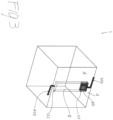
- the present invention in its more general definition as illustrated in figures 1 and 3 - relates to an electrical enclosure 1 which comprises a base wall 2, a top wall 3 and a plurality of lateral walls 4, 5, 6, 7 which delimit an internal volume 8 of the enclosure 1 into which a number of electrical apparatuses and equipment (not illustrated) can be housed.
- the geometry of the enclosure is squared so as to allow the combination of different units to form a switchboard.
- the various walls 2, 3, 4, 5, 6, 7 form a gas-tight enclosure into which a number of various electrical components are housed in a generally pressurized atmosphere of an insulating gas or mixture of gases.
- the electrical enclosure 1 of the invention further comprises a thermal exchange device 10 which has the purpose of remove the heat - generally due to the power losses - generated into the internal volume 8 of the enclosure 1, as explained in the introductory part of the description.
- a thermal exchange device 10 which has the purpose of remove the heat - generally due to the power losses - generated into the internal volume 8 of the enclosure 1, as explained in the introductory part of the description.
- One of the peculiar features of the enclosure 1 of the invention is due to the characteristics, in particular the design and positioning, of the thermal exchange device 10.
- the thermal exchange device 10 comprises a first thermal exchange assembly 11 which is positioned into the internal volume 8.
- the first thermal exchange assembly 11 comprises a first heat sink 110 and a first duct 12 that is provided with an inlet opening 121 and an outlet opening 122.
- the first duct 12 can in practice be a channel made of plastic material which is open towards the top 121 and the bottom 122, and is airtight on the sides.
- the first heat sink 110 is fitted in the inlet opening 121 of the first duct 12 in a tight manner and is attached on one of the lateral walls 4, 5, 6, 7 of the enclosure 1 (the rear wall 4 in the figures). In the embodiments shown in the figures, the first heat sink 110 is attached to the rear wall 4 in an upper half-portion of the internal volume 8 of the enclosure 1 and the first duct 12 is directed downwardly so that his outlet opening 122 is positioned in a lower half portion of the internal volume 8 of said enclosure 1.
- a circulation of gas inside the enclosure 1 is generated by the gas entering into the first heat sink 110 from the inlet opening 121 as shown by the arrow 300 in figure 3 . Due to the cooling of the gas when it comes into contact with the first heat sink 110 (which is at lower temperature), its density increases and consequently the gas moves downward through the first duct 12 and exit from the duct 12 through the outlet opening 122 as shown by the arrow 400.
- the first heat sink 110 is attached on a top portion of one of said lateral walls 4, 5, 6, 7, e.g., the rear wall 4, not too close to the top wall 3 - i.e., at a distance from the top wall 3 - to avoid hindering the flow of the gas into the first duct 12 through the inlet opening 121.
- the outlet opening 122 of the first duct 12 is positioned in the bottom portion of the internal volume 8 of the enclosure 1 not too close to the base wall 2, so as not to hinder the free exit of the gas from first duct 12 through the outlet opening 122.
- the first thermal exchange assembly 11 comprises a first thermal interface plate 13 made of a thermally conductive material which is positioned between the first heat sink 110 and the lateral wall 4, 5, 6, 7 e.g., the rear wall 4, onto which the first heat sink 110 is attached, to improve the thermal contact and the thermal exchange between the first heat sink 110 and the lateral wall 4 of the electrical enclosure 1.
- the first heat sink 110 comprises a plurality of fins 14 which are made of a thermal conductive material, e.g., aluminium. As shown in figure 3 , the fins 14 are exposed to the inflow of the gas into the duct 12 through the inlet opening 121 and are positioned on the thermal interface plate 13 which is in turn attached on the lateral wall 4 of the electrical enclosure 1. In this way the heat transfer from the relatively warm gas to the relatively colder outside ambient can be greatly enhanced.
- a thermal conductive material e.g., aluminium
- the fins 14 protrude perpendicularly from the thermal interface plate 13.
- Other arrangements of the fins 14, e.g., parallel to the thermal interface plate 13, are also possible, depending on the needs and the design of the heat sink.
- the inlet opening 121 of the first duct 12 is tightly fitted around a portion of the first heat sink 110.
- the distance of the walls of the duct 12 from the lateral fins 14 and from the tip of the fins 14 is minimal and is general lower than the pitch of the fins 14 positioned on the thermal interface plate 13.
- the thermal exchange device 10 comprises a second thermal exchange assembly 21 which is positioned outside the electrical enclosure 1 and which is in thermal exchange with the first thermal exchange assembly 11.
- the second thermal exchange assembly 21 comprises a second heat sink 210 and a second duct 22 that is provided with an inlet opening 221 and an outlet opening 222.
- the second duct 22 can in practice be a channel made of plastic material which is open towards an inlet 121 and outlet 122 extremes, and is airtight on the sides.
- the second heat sink 210 is attached on the outer surface of the lateral wall 4, 5, 6, 7 onto which said first heat sink 110 is attached - e.g., the rear wall 4 in the embodiment shown in the figures - in a position matching the position of said first heat sink 110 in the inner surface of, e.g., the rear wall 4.
- the inlet opening 221 of the second duct 22 tightly fitted around at least a portion of the second heat sink 210. Then, the second duct 22 is directed upwardly and its outlet opening 222, in the embodiment shown, is positioned over the enclosure 1, i.e., at a height above the top wall 3 of the electrical enclosure 1.
- the second thermal exchange assembly 21 uses the chimney effect in a reverse way with respect to the first thermal exchange assembly 11, as the second heat sink 210 is warmer than the surrounding ambient air. Therefore, the ambient air enters in the second heat sink 210 from the inlet opening 221 of the second duct 22, as shown by the arrow 500.
- the air is heated in the second heat sink 210 and has a lower density with respect to the surrounding air which is at lower temperature. Consequently, the air flow in the second duct 22 is directed upwardly towards the outlet opening 222 of the second duct 22, from which it exits as shown by the arrow 600.
- the first 110 and second 210 heat sink work in opposite way, the former being colder than the surrounding air (inside the enclosure 1) and generating an airflow directed downwards (as shown by arrows 300 and 400), the latter being warmer than the surrounding air (outside the enclosure 1) and generating an airflow directed upwards (as shown by arrows 500 and 600).
- the second thermal exchange assembly 21 comprises a second thermal interface plate 131 which is positioned between the second heat sink 210 and the lateral walls 4, 5, 6, 7 e.g., the rear wall 4, onto which the second heat sink 210 is attached.
- thermal interface plates 13 and 131 are positioned on both sides of, e.g., the rear enclosure wall 4, and consequently the thermal resistance in the system is further reduced.
- the second heat sink 210 comprises a plurality of fins 14 which are made of a thermal conductive material, e.g., aluminium.
- the fins 14 of the second heat sink 210 are positioned on the thermal interface plate 131 which is in thermal exchange with the first heat sink 110 and receive heat from it. Then, the fins 14 of the second heat sink 210 are exposed to the inflow of the gas into the duct 22 through the inlet opening 221, thereby transferring heat to the relatively colder outside ambient air.
- the fins 14 on both the first 110 and second 210 heat sinks protrude perpendicularly from the respective thermal interface plate 13 and 131.
- Other arrangement of the fins 14, e.g., parallel to the thermal interface plates 13 and 131, are also possible, depending on the needs and the design of the heat sinks.
- one of the lateral walls 4, 5, 6, 7 of the enclosure 1, e.g., the rear wall 4 is provided with an opening.
- the said first 110 and second 210 heat sinks are positioned on opposite sides of a common baseplate 140 which is attached on the relevant lateral wall, e.g., the rear wall 4, around said opening.
- the first heat sink 110 protrudes through the opening in the lateral wall, e.g., the rear wall 4, inside the internal volume 8 of the enclosure 1, while the second heat sink 210 remains outside.
- the common baseplate 140 is positioned on the lateral wall, e.g., the rear wall 4, so as to close said opening in a gas-tight way. As previously explained, with such embodiment, the thermal contact between both internal 8 and external sides of the enclosure 1 is further improved.
- the first heat sink 110 and the second heat sink 210 comprises a plurality of fins 14 which are made of a thermal conductive material, e.g., aluminium.
- the fins 14 of both the first heat sink 110 and the second heat sink 210 are positioned on the common baseplate 140 on opposite sides thereof.
- the fins 14 on both the first 110 and second 210 heat sinks protrude perpendicularly from the common baseplate 140.
- the fins 14 of the first heat sink 110 are exposed to the inflow of the gas into the duct 12 through the inlet opening 121 and transfer the heat to the fins 14 of the second heat sink 210 through the common baseplate 140.
- the fins 14 of the second heat sink 210 are exposed to the inflow of the ambient air into the duct 22 through the inlet opening 221, thereby transferring heat to the relatively colder outside ambient air.
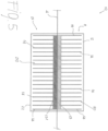
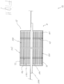
- the first 11 thermal exchange assembly and/or the second thermal exchange assembly 21 comprise a plurality of heat pipes 50.
- both the first 11 and the second 21 thermal exchange assembly are provided with heat pipes 50 in order to ensure a low thermal resistance between both sides.
- the first heat sink 110 and the second heat sink 210 comprises a plurality of fins 141 which are made of a thermal conductive material, e.g., aluminium, and which are positioned parallel to a common baseplate 140. Then, the heat pipes 50 are transversally positioned with respect to said plurality of fins 141 and cross both the first heat sink 110 and the second heat sink 210, as well as the common baseplate 140 which is interposed between them. Other arrangements of the fins 141 and of the heat pipes 50 are also possible, depending on the needs and the design of the thermal exchange device 10.
- the first duct 12 of the first thermal exchange assembly 110 and the second duct 22 of the second thermal exchange assembly 110 can have different shapes and dimensions, depending on the operating needs. Also, their positioning relative to the enclosure 1 can be different according to the needs and convenience.
- first duct 12 of the first thermal exchange assembly 110 can be positioned substantially attached to a lateral wall, e.g., the rear wall 4 onto which the first heat sink 110 is attached, as shown in figures 1 , 3 , 4 , and 6-8 .
- the first duct 12 is at least partially positioned at a distance from the lateral wall 4, 5, 6, 7, e.g., the rear wall 4, onto which the first heat sink 110 is attached. In this way, the heat transfer area between the gas in the internal volume 8 of the enclosure 1 and the wall 4, 5, 6, 7 of the enclosure 1 can be maximized.
- the first duct 12 has a narrower cross section in the bottom part with respect to the top part in order to create a gap between its wall and the the rear wall 4 of the enclosure 1 for the reasons explained above.
- the outlet opening 122 of the first duct 12 has a narrower section with respect to the corresponding inlet opening 121 due to the difference of the first duct 12 cross section between its top and bottom parts.
- the system of the present invention is particularly effective in gas insulated enclosures, and therefore a gas insulated switchgear is a specific object of the present invention From a manufacturing standpoint, the presently disclosed electrical enclosure is very easy to manufacture with consequent advantages in terms of costs.
Landscapes
- Engineering & Computer Science (AREA)
- Power Engineering (AREA)
- Aviation & Aerospace Engineering (AREA)
- Physics & Mathematics (AREA)
- Thermal Sciences (AREA)
- Microelectronics & Electronic Packaging (AREA)
- Cooling Or The Like Of Electrical Apparatus (AREA)
Priority Applications (2)
| Application Number | Priority Date | Filing Date | Title |
|---|---|---|---|
| EP23216160.4A EP4572044A1 (de) | 2023-12-13 | 2023-12-13 | Kühlsystem für elektrische gehäuse |
| CN202411475894.XA CN120149984A (zh) | 2023-12-13 | 2024-10-22 | 用于电气外壳的冷却系统 |
Applications Claiming Priority (1)
| Application Number | Priority Date | Filing Date | Title |
|---|---|---|---|
| EP23216160.4A EP4572044A1 (de) | 2023-12-13 | 2023-12-13 | Kühlsystem für elektrische gehäuse |
Publications (1)
| Publication Number | Publication Date |
|---|---|
| EP4572044A1 true EP4572044A1 (de) | 2025-06-18 |
Family
ID=89222427
Family Applications (1)
| Application Number | Title | Priority Date | Filing Date |
|---|---|---|---|
| EP23216160.4A Pending EP4572044A1 (de) | 2023-12-13 | 2023-12-13 | Kühlsystem für elektrische gehäuse |
Country Status (2)
| Country | Link |
|---|---|
| EP (1) | EP4572044A1 (de) |
| CN (1) | CN120149984A (de) |
Citations (3)
| Publication number | Priority date | Publication date | Assignee | Title |
|---|---|---|---|---|
| JPS62178710U (de) * | 1986-04-30 | 1987-11-13 | ||
| WO2015155426A1 (fr) * | 2014-04-10 | 2015-10-15 | Emerson Network Power Industrial Systems | Armoire electrique destinee aux applications en milieux a risques |
| US20190301811A1 (en) * | 2017-07-05 | 2019-10-03 | Noren Products Inc. | Heat exchanger assemblies and methods for cooling the interior of an enclosure |
-
2023
- 2023-12-13 EP EP23216160.4A patent/EP4572044A1/de active Pending
-
2024
- 2024-10-22 CN CN202411475894.XA patent/CN120149984A/zh active Pending
Patent Citations (3)
| Publication number | Priority date | Publication date | Assignee | Title |
|---|---|---|---|---|
| JPS62178710U (de) * | 1986-04-30 | 1987-11-13 | ||
| WO2015155426A1 (fr) * | 2014-04-10 | 2015-10-15 | Emerson Network Power Industrial Systems | Armoire electrique destinee aux applications en milieux a risques |
| US20190301811A1 (en) * | 2017-07-05 | 2019-10-03 | Noren Products Inc. | Heat exchanger assemblies and methods for cooling the interior of an enclosure |
Also Published As
| Publication number | Publication date |
|---|---|
| CN120149984A (zh) | 2025-06-13 |
Similar Documents
| Publication | Publication Date | Title |
|---|---|---|
| JP3469475B2 (ja) | 鉄道車両用半導体冷却装置 | |
| EP0356991B1 (de) | Wechselrichtervorrichtung | |
| RU2328798C2 (ru) | Заключенные в корпус коммутационные аппараты с теплоотражающими элементами | |
| JP5941741B2 (ja) | 電力変換装置 | |
| US10957621B2 (en) | Heat sink for a power semiconductor module | |
| JP2007273774A (ja) | コンデンサ冷却構造及び電力変換装置 | |
| EP4572044A1 (de) | Kühlsystem für elektrische gehäuse | |
| EP2001095B1 (de) | Buchse für Generator | |
| WO2016185613A1 (ja) | 電子機器 | |
| JP4298645B2 (ja) | 冷却手段を備えた高圧設備の区間 | |
| CN119889870B (zh) | 一种应用于一体化设备的封闭式变压器风冷波纹冷却装置 | |
| JP6555177B2 (ja) | 半導体モジュール | |
| CN115701823B (zh) | 一种充电设备和充电系统 | |
| CN220524325U (zh) | 电控部件以及空调器 | |
| JP3683796B2 (ja) | 電力変換装置 | |
| US10939586B2 (en) | Heat exchanger structure for a rack assembly | |
| US10015913B2 (en) | Power converter and cooler | |
| JP4385747B2 (ja) | 半導体装置の実装構造 | |
| KR101996616B1 (ko) | 방열 장치를 구비하는 전자기기 | |
| JP2011135649A (ja) | インバータ装置 | |
| CN218888888U (zh) | 一种变频电源及其散热结构 | |
| CN223414502U (zh) | 一种高效弯曲管道散热器 | |
| CN219677928U (zh) | 一种自循环散热型气体绝缘封闭开关装置 | |
| US20240334641A1 (en) | Electronics arrangement and semiconductor switching device having the electronics arrangement | |
| CN216450011U (zh) | 一种散热结构及服务器 |
Legal Events
| Date | Code | Title | Description |
|---|---|---|---|
| PUAI | Public reference made under article 153(3) epc to a published international application that has entered the european phase |
Free format text: ORIGINAL CODE: 0009012 |
|
| STAA | Information on the status of an ep patent application or granted ep patent |
Free format text: STATUS: THE APPLICATION HAS BEEN PUBLISHED |
|
| AK | Designated contracting states |
Kind code of ref document: A1 Designated state(s): AL AT BE BG CH CY CZ DE DK EE ES FI FR GB GR HR HU IE IS IT LI LT LU LV MC ME MK MT NL NO PL PT RO RS SE SI SK SM TR |
|
| STAA | Information on the status of an ep patent application or granted ep patent |
Free format text: STATUS: REQUEST FOR EXAMINATION WAS MADE |
|
| 17P | Request for examination filed |
Effective date: 20251029 |
|
| GRAP | Despatch of communication of intention to grant a patent |
Free format text: ORIGINAL CODE: EPIDOSNIGR1 |
|
| STAA | Information on the status of an ep patent application or granted ep patent |
Free format text: STATUS: GRANT OF PATENT IS INTENDED |
|
| INTG | Intention to grant announced |
Effective date: 20260209 |