EP4572043A1 - Elektrisches gehäuse - Google Patents
Elektrisches gehäuse Download PDFInfo
- Publication number
- EP4572043A1 EP4572043A1 EP24211389.2A EP24211389A EP4572043A1 EP 4572043 A1 EP4572043 A1 EP 4572043A1 EP 24211389 A EP24211389 A EP 24211389A EP 4572043 A1 EP4572043 A1 EP 4572043A1
- Authority
- EP
- European Patent Office
- Prior art keywords
- framework
- cover
- electrical box
- opening
- holes
- Prior art date
- Legal status (The legal status is an assumption and is not a legal conclusion. Google has not performed a legal analysis and makes no representation as to the accuracy of the status listed.)
- Pending
Links
Images


Classifications
-
- H—ELECTRICITY
- H02—GENERATION; CONVERSION OR DISTRIBUTION OF ELECTRIC POWER
- H02B—BOARDS, SUBSTATIONS OR SWITCHING ARRANGEMENTS FOR THE SUPPLY OR DISTRIBUTION OF ELECTRIC POWER
- H02B1/00—Frameworks, boards, panels, desks, casings; Details of substations or switching arrangements
- H02B1/26—Casings; Parts thereof or accessories therefor
- H02B1/40—Wall-mounted casings; Parts thereof or accessories therefor
- H02B1/44—Hinged covers or doors
-
- H—ELECTRICITY
- H02—GENERATION; CONVERSION OR DISTRIBUTION OF ELECTRIC POWER
- H02B—BOARDS, SUBSTATIONS OR SWITCHING ARRANGEMENTS FOR THE SUPPLY OR DISTRIBUTION OF ELECTRIC POWER
- H02B1/00—Frameworks, boards, panels, desks, casings; Details of substations or switching arrangements
- H02B1/26—Casings; Parts thereof or accessories therefor
- H02B1/28—Casings; Parts thereof or accessories therefor dustproof, splashproof, drip-proof, waterproof or flameproof
-
- H—ELECTRICITY
- H02—GENERATION; CONVERSION OR DISTRIBUTION OF ELECTRIC POWER
- H02B—BOARDS, SUBSTATIONS OR SWITCHING ARRANGEMENTS FOR THE SUPPLY OR DISTRIBUTION OF ELECTRIC POWER
- H02B1/00—Frameworks, boards, panels, desks, casings; Details of substations or switching arrangements
- H02B1/26—Casings; Parts thereof or accessories therefor
- H02B1/46—Boxes; Parts thereof or accessories therefor
-
- H—ELECTRICITY
- H02—GENERATION; CONVERSION OR DISTRIBUTION OF ELECTRIC POWER
- H02G—INSTALLATION OF ELECTRIC CABLES OR LINES, OR OF COMBINED OPTICAL AND ELECTRIC CABLES OR LINES
- H02G3/00—Installations of electric cables or lines or protective tubing therefor in or on buildings, equivalent structures or vehicles
- H02G3/02—Details
- H02G3/08—Distribution boxes; Connection or junction boxes
- H02G3/081—Bases, casings or covers
-
- H—ELECTRICITY
- H02—GENERATION; CONVERSION OR DISTRIBUTION OF ELECTRIC POWER
- H02G—INSTALLATION OF ELECTRIC CABLES OR LINES, OR OF COMBINED OPTICAL AND ELECTRIC CABLES OR LINES
- H02G3/00—Installations of electric cables or lines or protective tubing therefor in or on buildings, equivalent structures or vehicles
- H02G3/02—Details
- H02G3/08—Distribution boxes; Connection or junction boxes
- H02G3/088—Dustproof, splashproof, drip-proof, waterproof, or flameproof casings or inlets
-
- H—ELECTRICITY
- H02—GENERATION; CONVERSION OR DISTRIBUTION OF ELECTRIC POWER
- H02G—INSTALLATION OF ELECTRIC CABLES OR LINES, OR OF COMBINED OPTICAL AND ELECTRIC CABLES OR LINES
- H02G3/00—Installations of electric cables or lines or protective tubing therefor in or on buildings, equivalent structures or vehicles
- H02G3/02—Details
- H02G3/08—Distribution boxes; Connection or junction boxes
- H02G3/14—Fastening of cover or lid to box
-
- H—ELECTRICITY
- H05—ELECTRIC TECHNIQUES NOT OTHERWISE PROVIDED FOR
- H05K—PRINTED CIRCUITS; CASINGS OR CONSTRUCTIONAL DETAILS OF ELECTRIC APPARATUS; MANUFACTURE OF ASSEMBLAGES OF ELECTRICAL COMPONENTS
- H05K5/00—Casings, cabinets or drawers for electric apparatus
- H05K5/06—Hermetically-sealed casings
- H05K5/061—Hermetically-sealed casings sealed by a gasket held between a removable cover and a body, e.g. O-ring, packing
Definitions
- the present invention relates to a box for housing electrical components.
- the present invention preferably fits in the field of the food industry and/or in the medical field.
- the box subject-matter of the present invention specifically fits in environments and/or departments which are periodically controlled, and thus require frequent sanitisation.
- the place where the electrical box is located can be sanitised daily, weekly or monthly.
- the boxes used in this specific area are free, as far as possible, of cracks and grooves.
- the assembly of the box mainly involves welding between the various components that make it up. Thereby, constructive portions are eliminated which in their junction define cracks or joining spaces within which external agents can hide.
- the boxes are therefore mainly made as one piece, i.e. the main components are permanently assembled together, which makes it impossible to replace the individual damaged or worn parts.
- the boxes also have at least one access cover in the containment compartment, to allow any intervention on the electrical components.
- gaskets are provided between the cover and the containment framework that defines the inner compartment.
- gaskets are designed to prevent water vapours and moisture in general from accumulating over time along the inlets of the box, compromising the structure of the box itself as well as the electrical components present in the compartment.
- the gasket is a structural component of the box that requires special maintenance, as it requires periodic replacement in order to prevent its damage and/or deterioration from compromising the functionality of the box.
- the gasket no longer guarantees the insulation of the electrical components present in the housing of the box.
- the housing and the side surfaces of the box are places of accumulation of dust and dirt, which can jeopardize the integrity of the substantially sterile environment in which they are located.
- condensation i.e. the liquid residue that hides on the horizontal surfaces of the bottom wall and the top wall.
- the stagnant liquid compromises the structure of the box by chemically affecting the metal and deteriorating the surface of the box itself.
- condensation invalidates the correct sanitation and hygiene operations, increasing the formation of bacterial flora.
- the technical task of the present invention is thus to make available an electrical box which is able to overcome the prior-art drawbacks which have emerged.
- the object of the present invention is therefore to make available an electrical box capable of avoiding the retention of moisture, and facilitating the flow of fluids.
- a further object of the present solution is therefore to make available an electrical box that is able to limit the deposit of dust and/or other polluting residues.
- a further object of this solution is therefore to make available an electrical box that allows easy maintenance and therefore contained in economic terms.
- a further object of the present solution is therefore to make available an electrical box that is able to efficiently isolate the electrical components housed inside it from the water vapours sprayed during the sanitisation of the environments.
- an electrical box is made available.
- the electrical box comprises a framework.
- the framework defines a housing to accommodate electrical components.
- the framework has an opening for access to the housing.
- the framework has at least one flared side wall configured to define a preferential flow path.
- the electrical box comprises a cover.
- the cover comprises a peripheral inner frame.
- the electrical box further comprises a corresponding plurality of fixing elements.
- the fixing elements are configured to reversibly couple with respective first holes obtained in the cover and the framework to maintain the inner frame in contact with the framework.
- Each fixing element comprises a surface insulation gasket.
- the cover defines in collaboration with the framework a use configuration and a maintenance configuration.
- the inner frame is in contact with the framework to occlude the opening of the framework through the coupling of the fixing elements in the plurality of first holes.
- the cover occludes the opening of the framework.
- the plurality of first holes does not accommodate the plurality of fixing elements.
- the inner frame of the cover is spaced from the framework. In this way, in the maintenance configuration, the interior of the framework is accessible through the opening.
- the electrical box comprises a sealing gasket interposed between the cover and the framework.
- the electrical box further comprises coupling means reversibly fixed to the cover by means of the plurality of fixing elements.
- the coupling means are configured to define a peripheral seat with the inner frame of the cover.
- the sealing gasket is housed within the peripheral seat so as to waterproof the housing of the framework when the cover is in the use configuration.
- 1 indicates overall an electrical box for housing electrical components which, for simplicity of description, will be referred to below as an electrical box.
- electrical box 1 power boxes inside which for example, switches and/or electrical panels are stored.
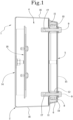
- the electrical box 1 comprises a framework 2 defining a housing 4 used to receive electrical components and having an opening 3 for access to the housing 4.
- the framework 2 of the electrical box 1 is preferably made mainly of stainless steel.
- the framework 2 has an installation wall opposite the opening 3 and adjacent side walls, placed between the installation wall and the opening 3, configured to circumscribe the housing 4 of the framework 2.
- the installation wall is parallel to the opening 3.
- the installation wall as shown in Figure 1 , comprises a plate 18 inside the housing 4 of the framework 2 configured to support electrical components.
- the installation wall comprises a system of external fixing to the housing 4 of the framework 2, configured to fix the electrical box 1 to an outer element.
- outer element is meant, for example, a wall of an environment to be sanitised.
- the external fixing system preferably has a circular shape and is made of stainless steel.
- the electrical box 1 is preferably placed vertically and hung on an outer element, for example a wall, with the opening 3 of the framework 2 opposite the outer element.
- one of the side walls or the installation wall may comprise a plurality of adjustable rest feet outside the housing 4 of the framework 2.
- the feet have threaded nuts according to a possible embodiment to facilitate coupling with the side wall.
- the framework 2 will comprise respectively either an external fixing system on the installation wall or feet on the side wall.
- the side walls are preferably four.
- the side walls are all equal to each other. In other words, the side walls have the same size and shape.
- the shape and size of the side walls and of the electrical box 1 may be various and different from the attached figures.
- the framework 2 has at least one flared side wall 16 configured to define a preferential flow path.
- flared means that the wall is not horizontal, but has a given inclination.
- the flared side wall 16 favours the outflow of water vapour residues and limits the deposit of dust and other contaminants.
- the flared side wall 16 converges towards the opening 3 of the framework 2.
- At least one flared side wall 16 has a given angular inclination "G" with respect to the opening 3 of the framework 2.
- the given angular inclination "G" defines outside the framework 2 an angle of less than 270° between the at least one flared side wall 16 and the opening 3.
- the electrical box 1 comprises a cover 5 comprising a peripheral inner frame 6.
- the cover 5 is preferably made mainly of stainless steel.
- the inner frame 6 projects inwardly towards the housing 4 of the framework 2.
- the inner frame 6 develops perpendicularly with respect to the cover 5, in the direction of the opening 3 of the framework 2.
- the electrical box 1 also comprises a corresponding plurality of fixing elements 9 configured to reversibly couple with respective first holes 7 obtained in the cover 5 and the framework 2 to maintain the inner frame 6 in contact with the framework 2.
- corresponding plurality means the co-presence of an equal number of fixing elements 9 and first holes 7 in the electrical box 1.
- the plurality of first holes 7 is preferably placed in the corners of the cover 5, as shown in Figure 3 .
- the position of the first holes 7 may be different from the attached figures.
- fixing elements 9 allows to avoid the irreversible welding of the components and thus, in the event of wear or damage, to allow the replacement of individual components, saving money on those parts which are still functioning, which can be disassembled with respect to the compromised piece and reused.
- the fixing elements 9 are made in the form of flat-headed threaded rivets.
- At least one fixing element 9 is made in the form of a flat-headed bolt.
- At least one fixing element 9 is made in the form of a flat-headed hexagonal screw, i.e. without an imprint.
- the flat head of the threaded rivet and/or the bolt and/or the hexagonal screw advantageously, allows to limit the accumulation of dust and other contaminants, which would otherwise be deposited in the notches present in the normal heads of the screws.
- Each fixing element 9 comprises a surface insulation gasket 12. In this way, each fixing element 9 (i.e. each threaded rivet or bolt) is protected from possible contaminants that in any case are reduced or absent given the characteristics already described and still to be described of the cover 5 and the framework 2.
- the insulation gasket 12 is made in the form of a tubular element wound on the surface of a respective threaded rivet (or bolt).
- each threaded rivet is inserted into the tubular insulation gasket 12.
- the insulation gasket 12 guarantees the waterproofing of the housing 4 of the framework 2, blocking the passage of liquids or water vapours that could hide between the plurality of first holes 7 and the fixing elements 9.
- the insulation gasket 12 is made of elastomeric material, in order to facilitate the insertion of the fixing element 9 inside the insulation gasket 12 itself.
- the isolation gasket 12 comprises a spacer.
- the spacer comprises fins configured to grip on the threads of the fixing elements 9.
- the spacer is preferably made of rigid polymeric material.
- the cover 5 defines in collaboration with the framework 2, thanks to the corresponding presence or absence of the fixing elements 9, a use configuration and a maintenance configuration.
- the inner frame 6 is in contact with the framework 2 to occlude the opening 3 of the framework 2.
- the occlusion of the opening 3 is guaranteed by the coupling between the fixing elements 9 and a plurality of first holes 7.
- the framework 2 with the cover 5, in said use configuration define a structure with a truncated pyramid shape.
- the framework 2 comprises a major base 14 defining the installation wall opposite the opening 3, while the cover 5 defines, in the use configuration, a minor base 15.
- Major base 14 means a wall of the framework 2 with a greater extension than the extension of the minor base 15, i.e. of the cover 5.
- the cover 5 and the framework 2 are spaced from each other, and the plurality of first holes 7 do not accommodate the plurality of fixing elements 9, leaving the opening 3 of the framework 2 free from engagements with other elements outside the framework 2 itself.
- the opening 3 of the framework 2 in the maintenance configuration guarantees access to the electrical components kept inside the housing 4.
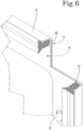
- the electrical box 1 further comprises coupling means 8 reversibly fixed to the cover 5 by means of the plurality of fixing elements 9, and configured to define a peripheral seat 10 with the inner frame 6 of the cover 5.
- the coupling means 8 are preferably made mainly of stainless steel.
- the fixing elements 9 ensure a secure mounting of the coupling means 8 to the cover 5, and since the fixing is reversible, they facilitate the maintenance of the individual components.
- the coupling means 8 are circumscribed within the inner frame 6 of the cover 5.
- the insulation gasket 12 of the fixing elements 9 is positioned, in the use configuration, between the framework 2 and the coupling means 8.
- tubular element is interposed, in use, between the framework 2 and the coupling means 8.
- the electrical box 1 further comprises a sealing gasket 11 interposed between the cover 5 and the framework 2.
- the sealing gasket 11 is housed within the peripheral seat 10 so as to waterproof the housing 4 of the framework 2 when the cover 5 is in the use configuration.
- sealing gasket 11 is configured to fit and expand between the coupling means 8 and the inner frame 6 of the cover 5.
- the sealing gasket 11 isolates the housing 4 from the water vapours sprayed during the sanitisation of the environments in which the electrical box 1 is located.
- the sealing gasket 11, being interposed between the coupling means 8 reversibly fixed to the inner frame 6 of the cover 5, is easily removable from the rest of the aforementioned components and therefore replaceable in case of wear.
- the spacer guarantees the reversible fixing of the assembly composed of the cover 5, the coupling means 8 and the sealing gasket 11, binding the fixing elements 9 to the assembly itself.
- the gasket has a portion insertable within the peripheral seat 10 having a dowel profile provided with one or more fins suitable for providing a reversible mating of the gasket in the peripheral seat 10.
- the sealing gasket 11 can be made of elastomeric material, in order to facilitate its insertion in the peripheral seat 10.
- the sealing gasket 11 is mainly made of polymeric material.
- the sealing gasket is made of silicone material.
- the framework 2 may further comprise, at the opening 3, a peripheral lip 13 configured to abut with the sealing gasket 11 when the cover 5 is in the use configuration.
- the peripheral lip 13 acts as an inner counter-frame, filling the voids created between the cover 5 and the framework 2.
- the peripheral lip 13 limits the passage of moisture inside the housing 4 of the framework 2 and prevents the deposit of dust and/or dirt in the areas surrounding the opening 3 of the framework 2.
- the peripheral lip 13 may in turn comprise a plurality of second holes 17 aligned with the at least a plurality of first holes 7 when the cover 5 is in the use configuration.
- the corresponding plurality of fixing elements 9 is configured to couple with the plurality of second holes 17.
- the plurality of second holes 17 is made in the form of threaded holes into which each flat-head threaded rivet is screwed.
- the screwing of the fixing elements 9 into the plurality of first and second holes 7, 17 favours the insulation of the housing 4, keeping the cover 5 in a fixed and secure position with respect to the framework 2.
- the screwing of the fixing elements 9 to the plurality of first and second holes 7, 17 allows to obtain, in the configuration of use, a stable seal between the cover 5 and the framework 2 so as to guarantee the waterproofing of the housing 4.
- the coupling means 8 may, in this case, have a plurality of third holes, in order to allow the passage of the fixing elements 9 through the plurality of first and second holes 7, 17.
- the coupling means 8 can also have a plurality of third holes aligned with the first holes 7 of the cover 5 and with the second holes 17 of the framework 2, when the cover 5 and the framework 2 are in the use configuration.
- the present invention makes available an electrical box 1 capable of overcoming the drawbacks arising from the prior art.
- the present invention allows to avoid the retention of moisture, and to facilitate the flow of fluids inside the housing 4.
- the present invention limits the deposition of dust and/or other polluting residues inside the housing 4.
- the present invention makes available an electrical box 1 whose maintenance is facilitated and therefore contained in time and economic terms.
- the present invention allows to efficiently isolate the electrical components housed inside the electrical box 1 from the water vapours sprayed during the sanitisation of the environments or from other unwanted external agents inside the housing 4.
Landscapes
- Engineering & Computer Science (AREA)
- Architecture (AREA)
- Civil Engineering (AREA)
- Structural Engineering (AREA)
- Power Engineering (AREA)
- Microelectronics & Electronic Packaging (AREA)
- Casings For Electric Apparatus (AREA)
Applications Claiming Priority (1)
| Application Number | Priority Date | Filing Date | Title |
|---|---|---|---|
| IT202300026490 | 2023-12-12 |
Publications (1)
| Publication Number | Publication Date |
|---|---|
| EP4572043A1 true EP4572043A1 (de) | 2025-06-18 |
Family
ID=89983169
Family Applications (1)
| Application Number | Title | Priority Date | Filing Date |
|---|---|---|---|
| EP24211389.2A Pending EP4572043A1 (de) | 2023-12-12 | 2024-11-07 | Elektrisches gehäuse |
Country Status (2)
| Country | Link |
|---|---|
| US (1) | US20250192530A1 (de) |
| EP (1) | EP4572043A1 (de) |
Citations (4)
| Publication number | Priority date | Publication date | Assignee | Title |
|---|---|---|---|---|
| DE29517327U1 (de) * | 1995-11-02 | 1997-03-06 | Ramsauer, Dieter, 42555 Velbert | Dichtung für Blechschranktüren |
| DE102009005716B4 (de) * | 2009-01-22 | 2014-01-02 | Rittal Gmbh & Co. Kg | Gehäuse |
| ITUA20162150A1 (it) * | 2016-03-31 | 2017-10-01 | Irinox S P A | Cassetta elettrica igienizzabile in lamiera di acciaio inox |
| GB2592857A (en) * | 2019-10-15 | 2021-09-15 | Millitec Food Systems Ltd | Housing assembly |
-
2024
- 2024-11-07 EP EP24211389.2A patent/EP4572043A1/de active Pending
- 2024-12-11 US US18/976,967 patent/US20250192530A1/en active Pending
Patent Citations (4)
| Publication number | Priority date | Publication date | Assignee | Title |
|---|---|---|---|---|
| DE29517327U1 (de) * | 1995-11-02 | 1997-03-06 | Ramsauer, Dieter, 42555 Velbert | Dichtung für Blechschranktüren |
| DE102009005716B4 (de) * | 2009-01-22 | 2014-01-02 | Rittal Gmbh & Co. Kg | Gehäuse |
| ITUA20162150A1 (it) * | 2016-03-31 | 2017-10-01 | Irinox S P A | Cassetta elettrica igienizzabile in lamiera di acciaio inox |
| GB2592857A (en) * | 2019-10-15 | 2021-09-15 | Millitec Food Systems Ltd | Housing assembly |
Non-Patent Citations (1)
| Title |
|---|
| "HYGIENIC EQUIPMENT DESIGN CRITERIA", EHEDG GUIDELINES - DOC 8 - 2ND ED., 1 April 2004 (2004-04-01), pages 1 - 16, XP055216714, Retrieved from the Internet <URL:http://www.ehedg.org/uploads/DOC_08_E_2004.pdf> [retrieved on 20150928] * |
Also Published As
| Publication number | Publication date |
|---|---|
| US20250192530A1 (en) | 2025-06-12 |
Similar Documents
| Publication | Publication Date | Title |
|---|---|---|
| US8492651B2 (en) | Housing | |
| US20080115418A1 (en) | Fire resistant access panel for ducts and air handling equipment | |
| US9603269B2 (en) | Modular enclosure and construction method | |
| EP4572043A1 (de) | Elektrisches gehäuse | |
| CA3030940C (en) | Switch cabinet having a frame and an interior fitting component, corresponding switch cabinet assembly, and corresponding interior fitting component | |
| US20180187400A1 (en) | Mixed material apron sink | |
| RU2722682C1 (ru) | Компоновка монтажной платы и соответствующий способ | |
| US20140354129A1 (en) | Modular enclosure | |
| KR950006170A (ko) | 클린 룸의 벽 부재와 벽을 세우는 방법 및 오염 방지 방법 | |
| US9160153B2 (en) | Side-open wet-location electrical box and cover | |
| CN102822437A (zh) | 用于闭门器的固定板和具有这种固定板的闭门器装置 | |
| US5649399A (en) | Cover panel system | |
| GB2269831A (en) | Floor drain | |
| US20250192525A1 (en) | Electrical cabinet | |
| US4580381A (en) | Frame | |
| GB2592857A (en) | Housing assembly | |
| CA2723863C (en) | Means for fixing of screening media, and use of such means | |
| EA032202B1 (ru) | Корпус, в частности промышленный корпус | |
| KR101454377B1 (ko) | 코밍유닛의 드레인플러그 | |
| KR101043020B1 (ko) | 외부 경관이 향상된 조립식 물탱크 | |
| US3080569A (en) | Mounting of flanged appliances in countertops | |
| JP2008166601A (ja) | 電気機器収納箱 | |
| US9806508B2 (en) | Electrical device box for mounting in a clean room | |
| KR101554929B1 (ko) | 하수 폐수 처리시설의 악취방지용 커버 | |
| JP5682123B2 (ja) | 建築物の外壁構造 |
Legal Events
| Date | Code | Title | Description |
|---|---|---|---|
| PUAI | Public reference made under article 153(3) epc to a published international application that has entered the european phase |
Free format text: ORIGINAL CODE: 0009012 |
|
| STAA | Information on the status of an ep patent application or granted ep patent |
Free format text: STATUS: THE APPLICATION HAS BEEN PUBLISHED |
|
| AK | Designated contracting states |
Kind code of ref document: A1 Designated state(s): AL AT BE BG CH CY CZ DE DK EE ES FI FR GB GR HR HU IE IS IT LI LT LU LV MC ME MK MT NL NO PL PT RO RS SE SI SK SM TR |
|
| STAA | Information on the status of an ep patent application or granted ep patent |
Free format text: STATUS: REQUEST FOR EXAMINATION WAS MADE |
|
| 17P | Request for examination filed |
Effective date: 20251210 |
|
| RAX | Requested extension states of the european patent have changed |
Extension state: BA Payment date: 20251210 |