EP4570946A2 - Zweikammerreaktor zur epitaktischen abscheidung von halbleitermaterial auf substraten - Google Patents
Zweikammerreaktor zur epitaktischen abscheidung von halbleitermaterial auf substraten Download PDFInfo
- Publication number
- EP4570946A2 EP4570946A2 EP24209839.0A EP24209839A EP4570946A2 EP 4570946 A2 EP4570946 A2 EP 4570946A2 EP 24209839 A EP24209839 A EP 24209839A EP 4570946 A2 EP4570946 A2 EP 4570946A2
- Authority
- EP
- European Patent Office
- Prior art keywords
- reactor
- tube
- reaction chamber
- reservoir
- cooling system
- Prior art date
- Legal status (The legal status is an assumption and is not a legal conclusion. Google has not performed a legal analysis and makes no representation as to the accuracy of the status listed.)
- Pending
Links
Images

Classifications
-
- C—CHEMISTRY; METALLURGY
- C23—COATING METALLIC MATERIAL; COATING MATERIAL WITH METALLIC MATERIAL; CHEMICAL SURFACE TREATMENT; DIFFUSION TREATMENT OF METALLIC MATERIAL; COATING BY VACUUM EVAPORATION, BY SPUTTERING, BY ION IMPLANTATION OR BY CHEMICAL VAPOUR DEPOSITION, IN GENERAL; INHIBITING CORROSION OF METALLIC MATERIAL OR INCRUSTATION IN GENERAL
- C23C—COATING METALLIC MATERIAL; COATING MATERIAL WITH METALLIC MATERIAL; SURFACE TREATMENT OF METALLIC MATERIAL BY DIFFUSION INTO THE SURFACE, BY CHEMICAL CONVERSION OR SUBSTITUTION; COATING BY VACUUM EVAPORATION, BY SPUTTERING, BY ION IMPLANTATION OR BY CHEMICAL VAPOUR DEPOSITION, IN GENERAL
- C23C16/00—Chemical coating by decomposition of gaseous compounds, without leaving reaction products of surface material in the coating, i.e. chemical vapour deposition [CVD] processes
- C23C16/44—Chemical coating by decomposition of gaseous compounds, without leaving reaction products of surface material in the coating, i.e. chemical vapour deposition [CVD] processes characterised by the method of coating
- C23C16/4411—Cooling of the reaction chamber walls
-
- C—CHEMISTRY; METALLURGY
- C30—CRYSTAL GROWTH
- C30B—SINGLE-CRYSTAL GROWTH; UNIDIRECTIONAL SOLIDIFICATION OF EUTECTIC MATERIAL OR UNIDIRECTIONAL DEMIXING OF EUTECTOID MATERIAL; REFINING BY ZONE-MELTING OF MATERIAL; PRODUCTION OF A HOMOGENEOUS POLYCRYSTALLINE MATERIAL WITH DEFINED STRUCTURE; SINGLE CRYSTALS OR HOMOGENEOUS POLYCRYSTALLINE MATERIAL WITH DEFINED STRUCTURE; AFTER-TREATMENT OF SINGLE CRYSTALS OR A HOMOGENEOUS POLYCRYSTALLINE MATERIAL WITH DEFINED STRUCTURE; APPARATUS THEREFOR
- C30B23/00—Single-crystal growth by condensing evaporated or sublimed materials
- C30B23/02—Epitaxial-layer growth
- C30B23/06—Heating of the deposition chamber, the substrate or the materials to be evaporated
-
- C—CHEMISTRY; METALLURGY
- C30—CRYSTAL GROWTH
- C30B—SINGLE-CRYSTAL GROWTH; UNIDIRECTIONAL SOLIDIFICATION OF EUTECTIC MATERIAL OR UNIDIRECTIONAL DEMIXING OF EUTECTOID MATERIAL; REFINING BY ZONE-MELTING OF MATERIAL; PRODUCTION OF A HOMOGENEOUS POLYCRYSTALLINE MATERIAL WITH DEFINED STRUCTURE; SINGLE CRYSTALS OR HOMOGENEOUS POLYCRYSTALLINE MATERIAL WITH DEFINED STRUCTURE; AFTER-TREATMENT OF SINGLE CRYSTALS OR A HOMOGENEOUS POLYCRYSTALLINE MATERIAL WITH DEFINED STRUCTURE; APPARATUS THEREFOR
- C30B25/00—Single-crystal growth by chemical reaction of reactive gases, e.g. chemical vapour-deposition growth
- C30B25/02—Epitaxial-layer growth
- C30B25/08—Reaction chambers; Selection of materials therefor
-
- C—CHEMISTRY; METALLURGY
- C30—CRYSTAL GROWTH
- C30B—SINGLE-CRYSTAL GROWTH; UNIDIRECTIONAL SOLIDIFICATION OF EUTECTIC MATERIAL OR UNIDIRECTIONAL DEMIXING OF EUTECTOID MATERIAL; REFINING BY ZONE-MELTING OF MATERIAL; PRODUCTION OF A HOMOGENEOUS POLYCRYSTALLINE MATERIAL WITH DEFINED STRUCTURE; SINGLE CRYSTALS OR HOMOGENEOUS POLYCRYSTALLINE MATERIAL WITH DEFINED STRUCTURE; AFTER-TREATMENT OF SINGLE CRYSTALS OR A HOMOGENEOUS POLYCRYSTALLINE MATERIAL WITH DEFINED STRUCTURE; APPARATUS THEREFOR
- C30B25/00—Single-crystal growth by chemical reaction of reactive gases, e.g. chemical vapour-deposition growth
- C30B25/02—Epitaxial-layer growth
- C30B25/10—Heating of the reaction chamber or the substrate
Definitions
- the semiconductor material to be deposited is silicon carbide, but other materials are not to be ruled out.
- the substrates to be deposited upon are typically also made of silicon carbide, but other materials are not to be ruled out.
- reaction chambers are able be maintained separately and independently of each other, i.e. that while performing maintenance on one of the chambers, another of the chambers can be operational, used to perform epitaxial deposition processes.
- Some examples of innovative multiple chamber reactors include: a first reaction chamber, a second reaction chamber, an induction heating system for said first and second reaction chambers, and a liquid cooling system for said first and second reaction chambers; said cooling system comprises a reservoir to contain and recirculate cooling liquid; said reservoir comprises a first reservoir section and a second reservoir section, in fluidic communication with each other
- Other examples of innovative multiple chamber reactor designs include: a first reaction chamber running along a first longitudinal direction, a second reaction chamber running along a second longitudinal direction, an induction heating system for said first and second reaction chambers, and a liquid cooling system for said first and second reaction chambers; said first longitudinal direction and said second longitudinal direction are parallel; said first reaction chamber and said second reaction chamber are located in two spaces, side by side, but separated at least by a metal plate; said metal plate is configured to isolate the reaction chambers from each other mechanically and/or fluidically and/or magnetically.
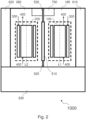
- Fig. 1 and Fig. 2 schematically show different aspects of the same example of reactor design 1000 for epitaxial deposition of semiconductor material on substrates.
- Reactor 1000 comprises a first reaction chamber 100 and a second reaction chamber 200. According to other design examples, the number of reaction chambers may be greater than two.
- reactor 1000 comprises a chamber heating system and a chamber cooling system.
- the heating system typically comprises distinct and/or independent components for each of the chambers.
- the cooling system typically comprises distinct and/or independent components for each of the chambers, but also typically at least one common reservoir.
- Fig. 2 the heating system is schematically indicated with 300.
- Fig. 1 schematically shows some possible components of the heating system 300, in particular (at least) one inductor 310 that is associated with or forms part of the first chamber and (at least) one inductor 320 that is associated with or forms part of the second chamber 200, as well as a power system 330 that powers the inductors 310 and 320.
- Induction heating for epitaxial reactor reaction chambers in particular, for hot-walled chambers used to deposit silicon carbide
- Fig. 2 the cooling system is shown schematically with reference 400.
- Fig. 1 shows, again schematically, some possible components of the cooling system 400, which will be specifically described below.
- Fig. 2 was intended to schematize a flow of coolant, specifically water, which first enters a hollow-walled (typically quartz) tube (element 110 of chamber 100 and element 210 of chamber 200), then flows along the tube, and finally exits the tube.
- the cooling system 400 is designed to recirculate the coolant, as shown in Fig. 2 .
- reactor 1000 includes:
- This heating system comprises a power system 330 that is typically comprised of a first power supply 331 for heating the first reaction chamber 100 and a second power supply 332 for heating the second reaction chamber 200.
- This cooling system comprises a reservoir 450 designed to contain and to recirculate cooling liquid.
- the reservoir 450 comprises a first reservoir section 452 and a second reservoir section 454; the first reservoir section 452 and the second reservoir section 454 are in fluidic communication with each other.
- the bottom of the first reservoir section 452 and the bottom of the second reservoir section 454 are flat and aligned; therefore, the bottom of the reservoir 450 is flat.
- the first reservoir section 452 and the second reservoir section 454 may be in fluidic communication through a conduit and/or valve and/or wall. In the example of Fig. 1 , such fluidic communication occurs through a wall 456 of predetermined height.
- the first reservoir section 452 and the second reservoir section 454 are in fluidic communication at a predetermined level, in particular with respect to a bottom level of said reservoir 450; as shown in Fig. 1 such predetermined level corresponds to the height of the wall 456 with respect to the bottom of the reservoir 450 which, in this case, is flat and unique.
- the reservoir 450 acts as a common reservoir for the chambers 100 and 200 if the liquid level is above that predetermined level.
- each of the reservoir sections would be independent of the other and could allow independent liquid recirculation cooling, in particular, the first section 452 for the first chamber 100 and the second section 454 for the second chamber 200, respectively.
- the reaction chamber 100 and the reaction chamber 200 comprise a hollow wall tube 110 and a hollow wall tube 210, respectively; the cavity of these tubes provides an annular conduit extending in the same longitudinal direction as the tube and along its entire length or substantially its entire length.
- Each of the hollow walls of the tubes is to be cooled by cooling fluid flowing along the cavity.
- the cooling system is configured to flow coolant, particularly water, first from the reservoir 450 to the tube 110 and to the tube 210, and then from the tube 110 and from the tube 210 back to the reservoir 450.
- the coolant enters the hollow wall tube on one side and exits the opposite side; along this path it extracts heat and then heats up; if the inlet temperature is for example 20°C the outlet temperature can be for example 30-40°C.
- the circulation of the cooling fluid is obtained by pump.
- the cooling system comprises a first pump 410 and a second pump 420; the first pump 410 is in fluidic communication with the first reservoir section 452 and the second pump 420 is in fluidic communication with the second reservoir section 454.
- the first pump 410 and the second pump 420 draw coolant from the bottom of the first reservoir section 452 and the second reservoir section 454 respectively and direct coolant to the reaction chambers, in particular the chamber tubes.
- Fig. 1 schematically shown are return ducts that drop from above directly into the reservoir sections and carry coolant from the reaction chambers, in particular from the chamber tubes, into the reservoir.
- return conduits that drop from above directly into the reservoir sections and carry coolant from the reaction chambers, in particular from the chamber tubes, into the reservoir.
- alternative configurations of such return conduits are foreseeable.
- the cooling system comprises a liquid cooler; depending on how it is constructed, such liquid cooler comprises several components.
- the purpose of such a liquid cooler is to reduce the temperature of the coolant exiting the reaction chambers, in particular from the chamber tubes.
- the coolant heats up as it flows into the reaction chambers and removes heat from the reaction chambers, and so it is advantageous for it to be forcibly cooled before entering the reaction chambers again, in particular the tubes of the chambers.
- the liquid cooler comprises a first heat exchanger 431 configured to cool cooling liquid directed to the first tube 110 through a flow of water from outside the reactor 1000; this flow is schematized in Fig. 1 with the line associated with the written indication "H2O" (bottom of Fig. 1 ).
- the heat exchanger 431 of Fig. 1 has been schematized as an element in contact with a conduit exiting the first pump 410. In this case, the coolant is cooled by the heat exchanger after it has exited the reservoir 450, in particular the first reservoir section 452.
- the liquid cooler comprises a second heat exchanger 432 configured to cool cooling liquid directed to the second tube 210 through a flow of water from outside the reactor 1000; such flow is schematized in Fig. 1 with the line associated with the written indication "H2O" (bottom of Fig. 1 ).
- the heat exchanger 432 of Fig. 1 has been schematized as an element in contact with a conduit exiting the second pump 420. In this case, the coolant is cooled by the heat exchanger after it has exited the reservoir 450, in particular the second reservoir section 454.
- the liquid cooler comprises a third heat exchanger 435 configured to cool cooling liquid present in the reservoir 450 through a flow of water from outside of reactor 1000; such flow is schematically in Fig. 1 with the line associated with the written indication "H2O" (bottom of Fig. 1 ).
- the heat exchanger 435 of Fig. 1 is intended to cool both the coolant present in the reservoir section 452 and in the reservoir section 454.
- the heat exchanger may be in contact with the side walls of the reservoir 450, in particular the reservoir section 452 and/or the reservoir section 454.
- the heat exchanger may consist of one or more coiled conduits inside the reservoir 450, in particular to the reservoir section 452 and/or the reservoir section 454, intended to facilitate the flow of water from outside the reactor.
- the liquid cooler comprises a fourth heat exchanger 431 configured to cool cooling liquid from the first tube 110 through a flow of water from outside of the reactor 1000; such flow is schematized in Fig. 1 with the line associated with the writing H2O (bottom of Fig. 1 ).
- the heat exchanger 431 of Fig. 1 has been schematized as an element in contact with a conduit exiting the tube 110. In this case, the coolant is cooled by the heat exchanger before returning to the reservoir 450, particularly in the first reservoir section 452.
- the liquid cooler comprises a fifth heat exchanger 432 configured to cool cooling liquid from the second tube 210 through a flow of water from outside of reactor 1000; such flow is schematically in Fig. 1 with the line associated with the writing H2O (bottom of Fig. 1 ).
- the heat exchanger 432 of Fig. 1 has been schematized as an element in contact with a conduit exiting the tube 210.
- the coolant is cooled by the heat exchanger before returning to the reservoir 450, particularly in the second reservoir section 454,
- the above refers to the cooling of the chambers, in particular the chamber tubes, in normal operating conditions.
- Such a cooling system is advantageous because the coolant content is known and/or controlled/controllable, because the coolant temperature (at various points in the circuit) can be known and/or controlled/controllable, because the coolant flow (pressure and/or speed) (at various points in the circuit) can be known and/or controlled/controllable.
- Such a cooling system is also advantageous because it is, at least in part, "redundant" thanks to the division of the tank into (partially) independent sections. Furthermore, since it is, in particular, an open circuit, it allows the tube, typically quartz, of the reaction chamber to be safeguarded by maintaining an adequate pressure, i.e. low and controlled.
- cooling system based on coolant contained in a tank and in particular recirculated for example through one or more pumps.
- the temperature inside the reaction chamber [can] reach very high values (at least 1000°C, but also 1600° and above, in the case of epitaxial deposition of silicon carbide at pressures e.g., between 0.1 and 1.0 atm) and that flammable (e.g., hydrogen and/or methane) and/or toxic (e.g., silane) gases may flow into the reaction chamber.
- flammable e.g., hydrogen and/or methane
- toxic e.g., silane
- the cooling system may advantageously comprise other components.
- cooling of the chamber or chambers may advantageously be carried out in another way.
- "breakage" e.g., tank or tank section or pipe
- breakage is defined as an event that results in a fluid leak (even if only small); for example, the leak could be at a hydraulic junction.
- the cooling system may be configured to flow cooling water taken from a stream of water from the outside of reactor 1000 (this flow is schematized in Fig. 1 with the line associated with written indication "H2O") into tube 110 and/or tube 210.
- This should typically only occur under pre-determined conditions, particularly in the event of failure or malfunction.
- This supply of water flow can be carried out selectively through valves (not shown in Fig. 1 ) controlled manually and/or electrically; for example, the control of these valves could be carried out for example by an electronic control system (not shown in Fig. 1 ).
- the ability to send H2O water (directly) to chambers 100 and 200 is represented by the two horizontal arrows exiting block 437 (bottom of Fig. 1 ) and the vertical arrows entering chambers 110 and 210 coming from block 437; note that block 437 is not strictly necessary and will be illustrated below.
- the cooling system is typically configured to drain cooling water from the tube 110 and/or the tube 210.
- This outflow may be directed towards the reservoir 450, as shown in Fig. 1 .
- this outflow can be directed into a special drain precisely because the cooling water comes from outside reactor 1000.
- This outflow can be carried out selectively through valves (not shown in Fig. 1 ) controlled manually and/or electrically; for example, the control of these valves could be carried out for example by an electronic control system (not shown in Fig. 1 ).
- the ability to drain water (directly) from chambers 100 and 200 is represented by the vertical arrows at the top exiting the chambers.
- the cooling system can be configured to process water from outside the reactor before flowing it into the tubes of the reactor chambers.
- the processing may be physical filtering.
- the block 437 is designed to provide, for example, both water processing (for example water treatment, such as water filtering) and water pressure reduction.
- reactor 1000 includes (as partly already shown with reference to Fig. 1 ):
- the first reaction chamber 100 and the second reaction chamber 200 are located in two spaces 180 and 280, side by side but separate.
- the separation is made by one or more (typically metal) plates and/or one or more (typically metal) panels.
- This separation is used to isolate reaction chambers from each other mechanically and/or fluidically and/or magnetically.
- a metal plate 510 is required, at least in correspondence to the reaction chambers 100 and 200; this metal plate 510 is configured to isolate the reaction chambers from each other at least magnetically.
- the heating system 300 is induction (magnetic) and therefore requires at least one inductor associated with each of the chambers.
- the inductors are typically solenoid, surrounding the chamber tubes and oriented along the longitudinal direction of tube development.
- the material of the metal plate 510 is preferably of high magnetic permeability.
- the material of the metal plate 510 is preferably aluminum or permalloy, more preferably aluminum.
- the metal plate 510 is preferably full and preferably 5-10 mm thick.
- the separation between the two gaps 180 and 280 can require both the metal plate 510 for magnetic isolation, and one or more metal panels 520 and 530 for mechanical and/or fluidic insulation.
- the plate is situated in such a way as to insulate magnetically, but also mechanically and fluidly.
- the panels are situated in such a way as to insulate mechanically and fluidly.
- the plate 510 is located centrally (with respect to the reactor support plane), at least a first panel (in particular panel 520) is located below (with respect to the reactor support plane) and at least a second panel (in particular panel 530) is located above (with respect to the reactor support plane).
- Both the plate and any panels are preferably full; however, it is possible that they can provide (small) openings for cable and/or conduit routing.
- a system 700 for managing the exhaust gases that exit the reaction chambers this figure shows the walls of its casing which is, for example, box-shaped.. Only one system is noted for all reaction chambers. In this design, the system is located in part in the area of the first reaction chamber 100 and in part in the area of the second reaction chamber 200. The enclosure of the implant 700 also contributes to the separation of the two spaces 180 and 280.
- reactor 1000 shown in Fig. 2 other spaces in addition to spaces 180 and 280 housing the reaction chambers 100 and 200 can be seen, in particular "maintenance spaces" (610, 620 and 630), i.e. spaces where personnel can perform maintenance operations on the reactor, in particular on the reactor's reaction chambers.
- maintenance spaces 610, 620 and 630
- personnel can perform maintenance operations on the reactor, in particular on the reactor's reaction chambers.
- openable panels are provided for access to maintenance spaces; some of the panels could/should be alarmed; others of the panels may be freely openable.
- the space 630 is useful, for example, for performing maintenance operations on a reaction chamber 100 or 200 (particularly on its gas inlet assembly) when it is retracted, for example thanks to a special slide on which the reaction chamber can rest, and moves into the space 630.
- the third maintenance space may be adjacent to spaces 180 and 610, and/or 280 and 620, as applicable.
- the space 610 is useful, for example, for performing maintenance operations on the reaction chamber 100, in particular on its gas discharge assembly (not shown in Fig. 2 ), which may be called “discharge cylinder", which is axially aligned with the reaction chamber near the system 700, which may be cylindrical in shape.
- the space 620 is useful, for example, for performing maintenance operations on the reaction chamber 200, in particular on its gas discharge assembly (not shown in Fig. 2 ), which may be called “discharge cylinder", which is axially aligned with the reaction chamber near the system 700, which may be cylindrical in shape.
- reactor 1000 may advantageously comprise both the components shown in Fig. 1 and the components shown in Fig. 2 , and may include others.
- the reactor 1000 may be protected by an outer shell, which may be continuous or partially interrupted, and composed of one or more outer panels.
- the one or more outer panels may enclose the reactor laterally, so as to provide the lateral portion of the outer shell.
- the one or more outer panels may also enclose the top and bottom portions of the reactor when it is standing for operation. so as to provide the top and bottom portions of the outer shell.
- the top portion of the outer shell of the reactor may advantageously comprise at least two panels adapted to swing open in case of overpressure of the reactor (or explosion).
- the at least two panels may be hinged and adapted to open and provide a safety vent when the pressure inside the reactor exceeds a predefined value.
Landscapes
- Chemical & Material Sciences (AREA)
- Metallurgy (AREA)
- Engineering & Computer Science (AREA)
- Materials Engineering (AREA)
- Organic Chemistry (AREA)
- General Chemical & Material Sciences (AREA)
- Chemical Kinetics & Catalysis (AREA)
- Crystallography & Structural Chemistry (AREA)
- Mechanical Engineering (AREA)
- Physical Or Chemical Processes And Apparatus (AREA)
- Chemical Vapour Deposition (AREA)
- Crystals, And After-Treatments Of Crystals (AREA)
- Liquid Deposition Of Substances Of Which Semiconductor Devices Are Composed (AREA)
Applications Claiming Priority (1)
| Application Number | Priority Date | Filing Date | Title |
|---|---|---|---|
| IT102023000022830A IT202300022830A1 (it) | 2023-10-31 | 2023-10-31 | Reattore per deposizione epitassiale di materiale semiconduttore su substrati con doppia camera di reazione |
Publications (2)
| Publication Number | Publication Date |
|---|---|
| EP4570946A2 true EP4570946A2 (de) | 2025-06-18 |
| EP4570946A3 EP4570946A3 (de) | 2025-11-26 |
Family
ID=89897363
Family Applications (1)
| Application Number | Title | Priority Date | Filing Date |
|---|---|---|---|
| EP24209839.0A Pending EP4570946A3 (de) | 2023-10-31 | 2024-10-30 | Zweikammerreaktor zur epitaktischen abscheidung von halbleitermaterial auf substraten |
Country Status (5)
| Country | Link |
|---|---|
| US (1) | US20250137122A1 (de) |
| EP (1) | EP4570946A3 (de) |
| JP (1) | JP2025076367A (de) |
| CN (1) | CN119913607A (de) |
| IT (1) | IT202300022830A1 (de) |
Family Cites Families (6)
| Publication number | Priority date | Publication date | Assignee | Title |
|---|---|---|---|---|
| JP2010171388A (ja) * | 2008-12-25 | 2010-08-05 | Hitachi Kokusai Electric Inc | 基板処理装置及び半導体装置の製造方法及び基板処理用反応管 |
| WO2011031672A2 (en) * | 2009-09-09 | 2011-03-17 | Applied Materials, Inc. | Parallel system for epitaxial chemical vapor deposition |
| TWI725854B (zh) * | 2020-05-19 | 2021-04-21 | 國立清華大學 | 群組式反應系統 |
| CN112746261B (zh) * | 2020-11-27 | 2023-08-29 | 乐金显示光电科技(中国)有限公司 | 一种冷却系统及其控制方法 |
| CN115274510A (zh) * | 2022-08-19 | 2022-11-01 | 北京北方华创微电子装备有限公司 | 一种半导体处理设备 |
| CN218932263U (zh) * | 2023-01-10 | 2023-04-28 | 光驰科技(上海)有限公司 | 一种用于真空镀膜的自动冷却系统 |
-
2023
- 2023-10-31 IT IT102023000022830A patent/IT202300022830A1/it unknown
-
2024
- 2024-10-28 JP JP2024189051A patent/JP2025076367A/ja active Pending
- 2024-10-28 CN CN202411509834.5A patent/CN119913607A/zh active Pending
- 2024-10-30 EP EP24209839.0A patent/EP4570946A3/de active Pending
- 2024-10-30 US US18/932,310 patent/US20250137122A1/en active Pending
Also Published As
| Publication number | Publication date |
|---|---|
| US20250137122A1 (en) | 2025-05-01 |
| EP4570946A3 (de) | 2025-11-26 |
| CN119913607A (zh) | 2025-05-02 |
| JP2025076367A (ja) | 2025-05-15 |
| IT202300022830A1 (it) | 2025-05-01 |
Similar Documents
| Publication | Publication Date | Title |
|---|---|---|
| CA2546687C (en) | Heat storage unit | |
| CN107636769B (zh) | 核反应堆、尤其是紧凑型的液态金属冷却核反应堆 | |
| KR101624561B1 (ko) | 격납부냉각계통 및 이를 구비한 원전 | |
| US20190132991A1 (en) | Liquid Cooling System And Method | |
| US20250137122A1 (en) | Two-chamber reactor for epitaxial deposition of semiconductor material on substrates | |
| WO2014112408A1 (ja) | 湿分分離加熱器、及びこれを備える湿分分離加熱設備 | |
| CN115350577B (zh) | 废气处理反应装置及半导体废气处理系统 | |
| CN105355244B (zh) | 乏燃料贮存及冷却系统 | |
| ZA200602629B (en) | Method and device for venting the primary circuit of a nuclear reactor | |
| JPH0659076A (ja) | 加圧水型原子炉の残留出力除去装置 | |
| KR102204730B1 (ko) | 회로에서 액체를 조절하는 시스템 | |
| KR101143220B1 (ko) | 압력용기 냉각 장치 | |
| US4713214A (en) | Device for purifying liquid metal coolant for a fast neutron nuclear reactor | |
| RS61922B1 (sr) | Postavka pločastog izmenjivača topline | |
| KR980010102A (ko) | 내부 응축 증기 배출 시스템 | |
| KR101400020B1 (ko) | 재기화 시스템 | |
| US12624451B2 (en) | Atomic layer deposition apparatus | |
| JP2023124344A (ja) | 高速炉の崩壊熱除去系熱交換器構造 | |
| CN220254954U (zh) | 液冷机柜 | |
| EP4392160A1 (de) | Verfahren für eine flüssigkeitsfilteranordnung | |
| CN113983852B (zh) | 换热器壳体结构及换热器 | |
| JPS61215804A (ja) | 建設機械の液体冷却装置 | |
| CN222378522U (zh) | 冷水机组及温控系统 | |
| CN110972448B (zh) | 换热系统 | |
| US20260113877A1 (en) | Filtration system for a coolant distribution unit |
Legal Events
| Date | Code | Title | Description |
|---|---|---|---|
| PUAI | Public reference made under article 153(3) epc to a published international application that has entered the european phase |
Free format text: ORIGINAL CODE: 0009012 |
|
| STAA | Information on the status of an ep patent application or granted ep patent |
Free format text: STATUS: THE APPLICATION HAS BEEN PUBLISHED |
|
| AK | Designated contracting states |
Kind code of ref document: A2 Designated state(s): AL AT BE BG CH CY CZ DE DK EE ES FI FR GB GR HR HU IE IS IT LI LT LU LV MC ME MK MT NL NO PL PT RO RS SE SI SK SM TR |
|
| PUAL | Search report despatched |
Free format text: ORIGINAL CODE: 0009013 |
|
| AK | Designated contracting states |
Kind code of ref document: A3 Designated state(s): AL AT BE BG CH CY CZ DE DK EE ES FI FR GB GR HR HU IE IS IT LI LT LU LV MC ME MK MT NL NO PL PT RO RS SE SI SK SM TR |
|
| RIC1 | Information provided on ipc code assigned before grant |
Ipc: C23C 16/44 20060101AFI20251020BHEP Ipc: C30B 23/06 20060101ALI20251020BHEP Ipc: C30B 25/10 20060101ALI20251020BHEP |
|
| STAA | Information on the status of an ep patent application or granted ep patent |
Free format text: STATUS: REQUEST FOR EXAMINATION WAS MADE |