EP4570677A1 - Bandspannvorrichtung - Google Patents
Bandspannvorrichtung Download PDFInfo
- Publication number
- EP4570677A1 EP4570677A1 EP22954995.1A EP22954995A EP4570677A1 EP 4570677 A1 EP4570677 A1 EP 4570677A1 EP 22954995 A EP22954995 A EP 22954995A EP 4570677 A1 EP4570677 A1 EP 4570677A1
- Authority
- EP
- European Patent Office
- Prior art keywords
- band
- control valve
- direction control
- air
- gripping mechanism
- Prior art date
- Legal status (The legal status is an assumption and is not a legal conclusion. Google has not performed a legal analysis and makes no representation as to the accuracy of the status listed.)
- Pending
Links
Images






Classifications
-
- B—PERFORMING OPERATIONS; TRANSPORTING
- B65—CONVEYING; PACKING; STORING; HANDLING THIN OR FILAMENTARY MATERIAL
- B65B—MACHINES, APPARATUS OR DEVICES FOR, OR METHODS OF, PACKAGING ARTICLES OR MATERIALS; UNPACKING
- B65B13/00—Bundling articles
- B65B13/18—Details of, or auxiliary devices used in, bundling machines or bundling tools
- B65B13/185—Details of tools
-
- B—PERFORMING OPERATIONS; TRANSPORTING
- B25—HAND TOOLS; PORTABLE POWER-DRIVEN TOOLS; MANIPULATORS
- B25B—TOOLS OR BENCH DEVICES NOT OTHERWISE PROVIDED FOR, FOR FASTENING, CONNECTING, DISENGAGING, OR HOLDING
- B25B25/00—Implements for fastening, connecting or tensioning of wire or strip
-
- B—PERFORMING OPERATIONS; TRANSPORTING
- B65—CONVEYING; PACKING; STORING; HANDLING THIN OR FILAMENTARY MATERIAL
- B65B—MACHINES, APPARATUS OR DEVICES FOR, OR METHODS OF, PACKAGING ARTICLES OR MATERIALS; UNPACKING
- B65B13/00—Bundling articles
- B65B13/18—Details of, or auxiliary devices used in, bundling machines or bundling tools
- B65B13/22—Means for controlling tension of binding means
Definitions
- the present invention relates to a band tightening device.
- Patent Document 1 discloses a band tightening device.
- the band tightening device includes a gripping mechanism, a reciprocating mechanism, and a return suppression mechanism.
- the gripping mechanism pulls a band with reciprocation in a predetermined direction.
- the reciprocating mechanism causes the gripping mechanism to reciprocate along a predetermined direction.
- the return suppression mechanism suppresses return of the band pulled by the gripping mechanism.
- the gripping mechanism includes a chuck base and a pressing gripper.
- the chuck base slides along a predetermined direction.
- the gripper repeats pressing and releasing of the band to and from the chuck base as the chuck base reciprocates.
- the chuck base has a pair of formation walls and a platform.
- the pair of formation walls forms an entry path of the band.
- the platform is continuous with the pair of formation walls so as to span the pair of formation walls.
- the gripper repeats pressing and releasing against the platform of the chuck base.
- the platform is provided with a slot.
- the band tightening device disclosed in Patent Document 1 can substantially prevent buckling of the band.
- Patent Document 1 JP 2005-239430 A
- Patent Document 1 has a problem that the band to be tightened is limited to some extent.
- An object of the present invention is to expand a range of a band to be tightened.
- a band tightening device 10 includes a housing 20 having a slide surface 72, a gripping mechanism 22, and a reciprocating mechanism 24.
- the gripping mechanism 22 pulls a band 500 with reciprocation along the slide surface 72.
- the reciprocating mechanism 24 causes the gripping mechanism 22 to reciprocate along the slide surface 72.
- the gripping mechanism 22 includes a chuck base 90 and a pressing gripper 92.
- the chuck base 90 is slidably in contact with the slide surface 72.
- the pressing gripper 92 presses the band 500 against the chuck base 90.
- the chuck base 90 has a pair of formation walls 110 and 110 and a band support portion 112.
- the pair of formation walls 110 and 110 each have a contact surface 130.
- the contact surface 130 contacts the slide surface 72.
- the pair of formation walls 110 and 110 constitutes an entry path 122 of the band 500.
- the band support portion 112 is continuous with the pair of formation walls 110 and 110 so as to span the pair of formation walls 110 and 110.
- the band support portion 112 has an inclined opposing surface 170.
- the inclined opposing surface 170 faces the entry path 122.
- the inclined opposing surface 170 is inclined with respect to the contact surface 130 so as to approach the contact surface 130 as approaching the entrance 120 of the band 500.
- the pressing gripper 92 slidably presses the band 500 against the inclined opposing surface 170 of the chuck base 90.
- the gripping mechanism 22 pulls a band 500 with reciprocation along the slide surface 72.
- the reciprocating mechanism 24 causes the gripping mechanism 22 to reciprocate along the slide surface 72.
- the gripping mechanism 22 includes the chuck base 90.
- the chuck base 90 includes the band support portion 112.
- the band support portion 112 has an inclined opposing surface 170.
- the pressing gripper 92 slidably presses the band 500 against the inclined opposing surface 170 of the chuck base 90.
- the band 500 contacts the inclined opposing surface 170 and is pulled. Since the band 500 can be pulled, restriction to the band 500 to be pulled is reduced.
- the band tightening device 10 of the present invention can expand a range of the band to be tightened.
- the gripping mechanism 22 described above desirably further includes a support 98.
- the support 98 supports the band 500 at the entrance 120 of the band 500.
- the chuck base 90 having pulled the band 500 is slid by the reciprocating mechanism 24 so as to return to an original position, a tension applied to the pulled band 500 is reduced.
- the portion of the band 500 that has entered the inside of the entry path 122 is likely to bend inside the entry path 122.
- the case is a case where the movement of the portion of the band 500 that does not enter the entrance 120 of the band 500 accompanying a reduction in tension is poor.
- the support 98 supports the band 500 at the entrance 120 of the band 500. Since the band 500 is supported by the support 98, even if a portion of the band 500 that becomes easy to bend is to bend, the bending is suppressed. As a result, the band 500 is prevented from bending inside the entry path 122.
- the support 98 described above desirably has the band support surface 190.
- the band support surface 190 faces the entrance 120 of the band 500.
- the band support surface 190 faces the entrance 120 of the band 500, the portion of the band 500 that becomes easy to be bent is supported by the band support surface 190.
- the region where the bending is suppressed in the portion that becomes easy to bend becomes larger than in a case where the portion is supported by a sharp object, for example. As a result, the band 500 is further prevented from bending inside the entry path 122.
- the band support surface 190 and the inclined opposing surface 170 described above desirably extend in directions intersecting each other.
- the band support surface 190 and the inclined opposing surface 170 extend in the directions intersecting each other.
- the band 500 is bent near the entrance 120 of the band 500 separately from the reduction in tension described above.
- the tension applied to the pulled band 500 is reduced, and thus, the possibility that the portion of the band 500 having once entered the inside of the entry path 122 returns again to the outside of the chuck base 90 becomes lower.
- the pressing gripper 92 slidably presses the band 500 against the inclined opposing surface 170 of the chuck base 90.
- the band support portion 112 described above desirably has a band ramp 172 in addition to the inclined opposing surface 170.
- the band ramp 172 is inclined with respect to the contact surface 130 so as to be away from the contact surface 130 as approaching the entrance 120 of the band 500.
- the band ramp 172 desirably connects the entrance 120 of the band 500 and the inclined opposing surface 170.
- the band tightening device 10 of the present invention can improve the force of pulling the band 500.
- the present invention can expand a range of a band to be tightened.
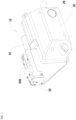
- Fig. 1 is a first external view of a band tightening device 10 according to the embodiment.
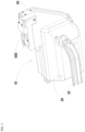
- Fig. 2 is a second external view of the band tightening device 10 according to the embodiment.
- Fig. 3 is a diagram illustrating the inside of the band tightening device 10 according to the embodiment. A configuration of the band tightening device 10 according to the embodiment will be described with reference to Figs. 1 to 3 .
- the band tightening device 10 is a device for tightening a band 500.
- the band tightening device 10 according to the embodiment includes a housing 20, a gripping mechanism 22, a reciprocating mechanism 24, a return suppression mechanism 26, a regulator 28, a cutting mechanism 30, and a holding arm 32.
- the housing 20 accommodates various components of the band tightening device 10 according to the embodiment. A specific configuration of the housing 20 according to the embodiment will be described later.
- the gripping mechanism 22 grips the band 500 and pulls the band 500. A specific configuration of the gripping mechanism 22 according to the embodiment will be described later.
- the reciprocating mechanism 24 causes the gripping mechanism 22 to reciprocate.
- a specific configuration of the reciprocating mechanism 24 according to the embodiment will be described later.
- the return suppression mechanism 26 suppresses return of the band 500 pulled by the gripping mechanism 22.
- a specific configuration of the return suppression mechanism 26 according to the embodiment will be described later.
- the regulator 28 is connected to an air introduction joint (not illustrated).
- the regulator 28 adjusts a pressure of air supplied from an air introduction source (not illustrated) via the air introduction joint to a predetermined pressure.
- the cutting mechanism 30 cuts the band 500.
- a specific configuration of the cutting mechanism 30 according to the embodiment will be described later.
- the holding arm 32 is fixed to the housing 20.
- a user of the band tightening device 10 according to the embodiment passes a hand of the user between the housing 20 and the holding arm 32. Accordingly, the band tightening device 10 is held.
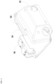
- Fig. 4 is a first external view of the housing 20 according to the embodiment.
- Fig. 5 is a second external view of the housing 20 according to the embodiment.
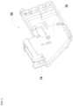
- Fig. 6 is an external view of a housing body 50 according to the embodiment.
- Fig. 7 is a diagram of a vicinity of a slide surface 72 of the housing body 50 according to the embodiment. A configuration of the housing 20 according to the embodiment will be described with reference to Figs. 4 to 7 .
- the housing 20 includes a housing body 50, a first housing cover 52, a second housing cover 54, and a chuck cover 56.
- the housing body 50 includes an accommodation portion 70, the slide surface 72, and a return suppression mechanism fixing portion 74.
- the accommodation portion 70 accommodates the gripping mechanism 22, the reciprocating mechanism 24, a part of the return suppression mechanism 26, the regulator 28, and a part of the cutting mechanism 30.
- the slide surface 72 serves as a passage for the gripping mechanism 22 to reciprocate. Another part of the return suppression mechanism 26 is fixed to the return suppression mechanism fixing portion 74.
- the first housing cover 52 covers one side surface of the housing body 50.
- the second housing cover 54 covers another side surface of the housing body 50.
- the holding arm 32 described above is fixed to the second housing cover 54 of the housing 20.
- the chuck cover 56 is fixed to the housing body 50 so as to cover the slide surface 72.
- Fig. 8 is a diagram illustrating a configuration of the gripping mechanism 22 according to the embodiment.
- Fig. 9 is a sectional view of the gripping mechanism 22 according to the embodiment.
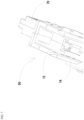
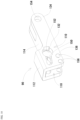
- Fig. 10 is a first external view of a chuck base 90 according to the embodiment.
- Fig. 11 is a second external view of the chuck base 90 according to the embodiment.
- Fig. 12 is an external view of a pressing gripper 92 according to the embodiment.
- Fig. 13 is an external view of an elastic body guide 96 according to the embodiment.
- Fig. 14 is an external view of a support 98 according to the embodiment. Configurations of the gripping mechanism 22 and the reciprocating mechanism 24 according to the embodiment will be described with reference to Figs. 8 to 14 .
- the gripping mechanism 22 includes the chuck base 90, the pressing gripper 92, a pair of holding elastic bodies 94 and 94, the elastic body guide 96, the support 98, and a pair of support fixing pins 100 and 100.
- the chuck base 90 is slidably in contact with the slide surface 72.
- the pressing gripper 92 presses the band 500 against the chuck base 90. At that time, the band 500 is pressed so as to be slidable.
- the holding elastic bodies 94 press the pressing gripper 92.
- the holding elastic bodies 94 include a known coil spring.
- the elastic body guide 96 restricts a direction in which the holding elastic bodies 94 extend and contract.
- the support 98 supports the band 500.
- the support fixing pins 100 fix the support 98 to the chuck base 90.
- the chuck base 90 includes a pair of formation walls 110 and 110, a band support portion 112, and a band entry prevention portion 114.
- the pair of formation walls 110 and 110 forms an entrance 120 of the band 500 and an entry path 122 of the band 500.
- the band support portion 112 is continuous with the pair of formation walls 110 and 110 so as to span the pair of formation walls 110 and 110.
- the band entry prevention portion 114 is continuous with the pair of formation walls 110 and 110 so as to connect the pair to each other.
- the pair of formation walls 110 and 110, the band support portion 112, and the band entry prevention portion 114 according to the embodiment are integrated.
- the formation wall 110 includes a contact surface 130, a long hole formation portion 132, a coupling pin through hole formation portion 134, and a support fixing pin through hole formation portion 136.
- the contact surface 130 contacts the slide surface 72.
- a long hole 150 and a guide through hole 152 are formed in the long hole formation portion 132.
- the long holes 150 and 150 opened in the pair of long hole formation portions 132 of the formation walls 110 and 110 face each other.
- the long holes 150 and 150 are inclined with respect to the contact surface 130.
- the long holes 150 and 150 are inclined so as to be away from the contact surface 130 as approaching the entrance 120 of the band 500.
- the pressing gripper 92 according to the embodiment slidably penetrates both the long holes 150 and 150.
- the guide through holes 152 and 152 opened in the pair of formation walls 110 and 110 also face each other.
- the elastic body guide 96 penetrates the guide through holes 152 and 152.
- Grooves are formed at both ends of the elastic body guide 96.
- the holding elastic bodies 94 are disposed in the grooves and the long holes 150.
- a coupling pin through hole 154 is formed in the coupling pin through hole formation portion 134.
- a support fixing pin through hole 156 is formed in the support fixing pin through hole formation portion 136.
- the band support portion 112 includes an inclined opposing surface 170 and a band ramp 172.
- the inclined opposing surface 170 faces the entry path 122 of the band 500.
- the inclined opposing surface 170 is inclined with respect to the contact surface 130 so as to approach the contact surface 130 as approaching the entrance 120 of the band 500.
- the band ramp 172 is inclined with respect to the contact surface 130 so as to be away from the contact surface 130 as approaching the entrance 120 of the band 500.
- the band ramp 172 connects the entrance 120 of the band 500 and the inclined opposing surface 170.
- the support 98 includes a band support surface 190 and a support surface fixing portion 192.
- the band support surface 190 according to the embodiment is a plane facing the entrance 120 of the band 500.
- the support 98 according to the embodiment supports the band 500 at the entrance 120 of the band 500.
- the band support surface 190 has a region protruding from the entrance 120 of the band 500 to the outside of the chuck base 90.
- the band support surface 190 extends along the contact surface 130 of the formation wall 110.
- the band support surface 190 and the inclined opposing surface 170 extend in directions intersecting each other.
- the support surface fixing portion 192 fixes the band support surface 190 to the chuck base 90.
- a hole through which the support fixing pins 100 and 100 penetrate is formed in the support surface fixing portion 192.
- Fig. 15 is a diagram illustrating a configuration of the reciprocating mechanism 24 according to the embodiment.
- Fig. 16 is a diagram illustrating a passage formed in a manifold 210 according to the embodiment. A configuration of the reciprocating mechanism 24 according to the embodiment will be described with reference to Figs. 15 and 16 .
- the reciprocating mechanism 24 includes the manifold 210, a reciprocating mechanism direction control valve 212, a speed controller 214, a gripping mechanism driving actuator 216, a switching lever-equipped direction control valve 218, an activation direction control valve 220, a drive switching pin 222, a reciprocating link 224, a reciprocating link swing center pin 226, and a gripping mechanism coupling pin 228.
- these components are connected to each other by a known tube. How the components are connected will be described below.
- the manifold 210 is connected to the regulator 28.
- the manifold 210 constitutes the following six passages.
- a first passage is an air passage 310 between the regulator 28 and the reciprocating mechanism direction control valve 212.
- This passage is connected to the regulator 28 by a known joint connected to the air passage 310 in Fig. 16 and a pipe (not illustrated).
- a second passage among the passages is one air passage 312 between the reciprocating mechanism direction control valve 212 and the gripping mechanism driving actuator 216.
- a third passage among the passages is another air passage 314 between the reciprocating mechanism direction control valve 212 and the gripping mechanism driving actuator 216.
- a fourth passage among the passages is another passage branched from another air passage 314 between the reciprocating mechanism direction control valve 212 and the gripping mechanism driving actuator 216.
- this passage is referred to as a branch passage 316.
- the branch passage 316 is connected to the speed controller 214 by a known joint continuous with the branch passage 316 in Fig. 16 and a pipe (not illustrated).
- a fifth passage among the passages is one exhaust passage 350 continuous with the reciprocating mechanism direction control valve 212.
- a sixth passage among the passages is another exhaust passage 352 continuous with the reciprocating mechanism direction control valve 212.
- the reciprocating mechanism direction control valve 212 is connected to the regulator 28, the speed controller 214, and the gripping mechanism driving actuator 216 via the manifold 210.
- the reciprocating mechanism direction control valve 212 is also connected to the switching lever-equipped direction control valve 218 and the activation direction control valve 220.
- the reciprocating mechanism direction control valve 212 switches a passage of air supplied from the regulator 28 and supplied to the gripping mechanism driving actuator 216 in accordance with air supplied from the switching lever-equipped direction control valve 218.
- the speed controller 214 is connected to the reciprocating mechanism direction control valve 212 and the gripping mechanism driving actuator 216 via the branch passage 316.
- the speed controller 214 is also connected to the cutting mechanism 30 via an air passage 340 (described later) for linking the reciprocating mechanism 24 and the cutting mechanism 30.
- the speed controller 214 is connected to a cutting mechanism direction control valve 280 of the cutting mechanism 30.
- the speed controller 214 supplies air to the cutting mechanism direction control valve 280.
- the gripping mechanism driving actuator 216 is connected to the reciprocating mechanism direction control valve 212 via the manifold 210.
- the gripping mechanism driving actuator 216 drives the reciprocating link 224.
- the gripping mechanism driving actuator 216 according to the embodiment is implemented by a known air cylinder.
- the switching lever-equipped direction control valve 218 is connected to the reciprocating mechanism direction control valve 212 and the activation direction control valve 220.
- the switching lever-equipped direction control valve 218 controls the reciprocating mechanism direction control valve 212 by supplying air.
- the switching lever-equipped direction control valve 218 according to the embodiment includes a switching valve body 240, a first switching lever 242, and a second switching lever 244.
- the activation direction control valve 220 and the reciprocating mechanism direction control valve 212 are directly connected to the switching valve body 240.
- the first switching lever 242 changes the path of air in the switching valve body 240.
- air supplied from an air introduction source (not illustrated) flows to the activation direction control valve 220.
- the second switching lever 244 When pressed by the drive switching pin 222, the second switching lever 244 changes the path of air in the switching valve body 240. As a result, air supplied from an air introduction source (not illustrated) flows to the reciprocating mechanism direction control valve 212 without passing through the activation direction control valve 220. Since the structure of the switching valve body 240 for operating in this manner is well known, the detailed description of the structure will not be repeated here.
- the stroke of the gripping mechanism driving actuator 216 according to the embodiment does not keep pressing the first switching lever 242 after the first switching lever 242 changes the path of air in the switching valve body 240.
- the stroke of the gripping mechanism driving actuator 216 according to the embodiment does not keep pressing the second switching lever 244 after the second switching lever 244 changes the path of air in the switching valve body 240. This configuration prevents damage to the first switching lever 242 and the second switching lever 244.
- the activation direction control valve 220 is connected to the switching lever-equipped direction control valve 218 and the reciprocating mechanism direction control valve 212.
- the activation direction control valve 220 according to the embodiment includes a start button 250 and an activation valve body 252.
- the start button 250 transmits a force received by the activation valve body 252.
- the activation valve body 252 opens an air passage 322 described below.
- the air passage 322 is an air passage 322 passing through the activation direction control valve 220 between the reciprocating mechanism direction control valve 212 and the switching lever-equipped direction control valve 218.
- the activation valve body 252 closes the air passage 322.
- the drive switching pin 222 couples the gripping mechanism driving actuator 216 and the reciprocating link 224. Furthermore, the drive switching pin 222 presses the first switching lever 242 and the second switching lever 244 of the switching lever-equipped direction control valve 218.
- the reciprocating link 224 transmits power supplied by the gripping mechanism driving actuator 216 to the gripping mechanism 22.
- the reciprocating link swing center pin 226 swingably fixes the reciprocating link 224. Accordingly, the reciprocating link 224 swings in accordance with the power supplied by the gripping mechanism driving actuator 216.
- the reciprocating link swing center pin 226 is fixed to the accommodation portion 70 of the housing body 50.
- the gripping mechanism coupling pin 228 connects the reciprocating link 224 to the pair of formation walls 110 and 110 of the chuck base 90.
- the gripping mechanism coupling pin 228 penetrates the coupling pin through holes 154 and 154 of the chuck base 90. Furthermore, the gripping mechanism coupling pin 228 is fitted into a groove at one end of the reciprocating link 224. As a result, the gripping mechanism 22 is driven to reciprocate with the swing of the reciprocating link 224.
- Fig. 17 is a diagram illustrating a configuration of the return suppression mechanism 26 according to the embodiment.
- Fig. 18 is a perspective view of a return suppression gripper 262 and a gripper pressing lever 264 according to the embodiment.
- Fig. 19 is a sectional view of the return suppression mechanism 26 according to the embodiment. A configuration of the return suppression mechanism 26 according to the embodiment will be described with reference to Figs. 17 to 19 .
- the return suppression mechanism 26 includes a lock base 260, the return suppression gripper 262, the gripper pressing lever 264, a pressing coil spring 266, and a lever swing center pin 268.
- the lock base 260 is fixed to the return suppression mechanism fixing portion 74 of the housing body 50.
- the lock base 260 forms a space in which the return suppression gripper 262 is accommodated and through which the band 500 penetrates.
- a pair of return suppression gripper fitting long holes 270 and 270 is formed in the lock base 260. Both ends of the return suppression gripper 262 are fitted into the pair of return suppression gripper fitting long holes 270 and 270.
- the gripper pressing lever 264 presses the return suppression gripper 262.
- One end of the pressing coil spring 266 is placed on a spring support plate 76 provided inside the housing body 50. Another end of the pressing coil spring 266 presses the gripper pressing lever 264.
- the lever swing center pin 268 penetrates the lock base 260.
- the lever swing center pin 268 swingably fixes the gripper pressing lever 264.
- Another end of the pressing coil spring 266 presses the gripper pressing lever 264, and then, the gripper pressing lever 264 swings about the lever swing center pin 268.
- the swung gripper pressing lever 264 presses the return suppression gripper 262 as described above.
- Both ends of the pressed return suppression gripper 262 are fitted into the return suppression gripper fitting long holes 270 formed in the lock base 260. Accordingly, the pressed return suppression gripper 262 is pushed up along the return suppression gripper fitting long holes 270. At this time, when the band 500 penetrates the lock base 260, the return suppression gripper 262 being pushed up presses the band 500 against the inner peripheral surface of the lock base 260.
- Fig. 20 is a diagram illustrating a configuration of the cutting mechanism 30 according to the embodiment. A configuration of the cutting mechanism 30 according to the embodiment will be described with reference to Fig. 20 . Although not illustrated in Fig. 20 , the cutting mechanism direction control valve 280 and the cutting mechanism driving actuator 282 are connected to each other by a pipe for passing air. How the components are connected will be described below.
- the cutting mechanism 30 includes the cutting mechanism direction control valve 280, the cutting mechanism driving actuator 282, an actuator coupling pin 284, a pair of transmission links 286 and 286, a link coupling pin 288, a swing link 290, an swing center pin 292, a cutter body coupling pin 294, a cutter body 296, and a cutter guide 298.
- the cutting mechanism direction control valve 280 is connected to an air introduction source (not illustrated), the speed controller 214, and the cutting mechanism driving actuator 282.
- the cutting mechanism direction control valve 280 controls a direction in which air supplied from an air introduction source (not illustrated) flows. This control is executed in accordance with the air supplied from the speed controller 214.
- the cutting mechanism driving actuator 282 supplies power for causing the cutter body 296 to reciprocate.
- the cutting mechanism driving actuator 282 is driven by air supplied from an air introduction source (not illustrated).
- the direction in which the air flows is controlled by the cutting mechanism direction control valve 280.
- the cutting mechanism driving actuator 282 is a known actuator driven by air.
- the actuator coupling pin 284 couples the cutting mechanism driving actuator 282 and the pair of transmission links 286 and 286.
- the pair of transmission links 286 and 286 transmits the power supplied by the cutting mechanism driving actuator 282 to the swing link 290.
- the link coupling pin 288 couples the pair of transmission links 286 and 286 and the swing link 290.
- the swing link 290 transmits the power transmitted from the pair of transmission links 286 and 286 to the cutter body 296.
- the swing center pin 292 penetrates a hole formed in the lock base 260.
- the swing center pin 292 is fixed to the return suppression mechanism 26.
- the swing center pin 292 swingably fixes the swing link 290. Accordingly, the swing link 290 swings in accordance with the power supplied by the cutting mechanism driving actuator 282.
- the cutter body coupling pin 294 couples the swing link 290 and the cutter body 296.
- the cutter body 296 cuts the band 500.
- the cutter guide 298 is fixed to the lock base 260.
- a recess (not illustrated) is formed in the cutter guide 298.
- the cutter body 296 can ascend and descend while being fitted in the recess. Accordingly, the cutter guide 298 restricts a moving direction of the cutter body 296 pushed up by the swing link 290. As a result, the cutter body 296 moves up and down in accordance with the movement of the swing link 290.
- the band tightening device 10 is manufactured by connecting components constituting the band tightening device.
- the methods for manufacturing those components are well known and are not described here in detail.
- the gripping mechanism 22 is connected in the following procedure.
- the pressing gripper 92 penetrates the guide through holes 152 and 152 of the chuck base 90.
- the pressing gripper 92 is then moved into the long holes 150 and 150.
- the elastic body guide 96 is made to penetrate the guide through holes 152 and 152.
- the holding elastic bodies 94 are fitted into the grooves and the long holes 150 and 150 formed at both ends of the elastic body guide 96.
- each of the support fixing pins 100 and 100 penetrates each of the support fixing pin through hole formation portions 136 and 136 of the formation walls 110 of the chuck base 90.
- the support fixing pins 100 and 100 also penetrate the hole of the support surface fixing portion 192 of the support 98 disposed in advance between the pair of formation walls 110 and 110.
- the gripping mechanism 22 according to the embodiment is completed.
- Fig. 21 is a diagram illustrating a pneumatic device included in the band tightening device 10 according to the embodiment and a connection relationship therebetween. A method of using the band tightening device 10 according to the embodiment will be described with reference to Figs. 1 to 21 .
- the regulator 28 When air is supplied from an air introduction source (not illustrated) to the band tightening device 10 according to the embodiment, part of the air is sent to the regulator 28. Another part of the air is sent to the switching lever-equipped direction control valve 218. Still another part of the air is sent to the cutting mechanism direction control valve 280.
- the regulator 28 supplied with air adjusts a pressure of the air to a predetermined pressure.
- the air is supplied to the reciprocating mechanism direction control valve 212.
- the air is supplied from the regulator 28 to the reciprocating mechanism direction control valve 212 via the air passage 310 therebetween.
- the air is supplied from an air introduction source (not illustrated) to the switching lever-equipped direction control valve 218 via an air passage 320 therebetween.
- the air is supplied from an air introduction source (not illustrated) to the cutting mechanism direction control valve 280 via an air passage 330 therebetween.
- the air supplied to the reciprocating mechanism direction control valve 212 is supplied to the gripping mechanism driving actuator 216.
- the air passes through the other air passage 314 between the reciprocating mechanism direction control valve 212 and the gripping mechanism driving actuator 216.
- the gripping mechanism driving actuator 216 pulls the reciprocating link 224.
- the air supplied to the cutting mechanism direction control valve 280 is supplied to the cutting mechanism driving actuator 282.
- the air passes through the air passage 332 between the cutting mechanism direction control valve 280 and a vicinity of a piston penetration portion of a cylinder of the cutting mechanism driving actuator 282.
- the air flows from the cutting mechanism driving actuator 282 to the cutting mechanism direction control valve 280 in the air passage 334 between the cutting mechanism direction control valve 280 and a vicinity of a cylinder bottom of the cutting mechanism driving actuator 282.
- the air is discharged to atmosphere via the cutting mechanism direction control valve 280.
- the piston of the cutting mechanism driving actuator 282 is accommodated in the cylinder.
- the band 500 is wound around an object in advance.
- the object around which the band 500 is wound is not illustrated.
- a tip of the band 500 is tightened, the object around which the band 500 is wound is bound by the band 500.
- An operator places the tip of the band 500 on the cutter guide 298 of the band tightening device 10 according to the embodiment.
- the tip of the band 500 is placed, and then, the operator directly pushes the tip of the band 500 into the band tightening device 10 according to the embodiment.
- the tip of the band 500 penetrates inside of the lock base 260.
- the tip of the band 500 penetrating inside of the lock base 260 passes through the entrance 120 formed in the chuck base 90.
- the tip of the band 500 having passed through the entrance 120 penetrates the entry path 122.
- the band entry prevention portion 114 prevents the tip of the band 500 penetrating the entry path 122 from entering the inside of the band tightening device 10 according to the embodiment. As a result, the tip of the band 500 penetrating the entry path 122 comes out of the band tightening device 10 according to the embodiment.
- the activation valve body 252 of the activation direction control valve 220 is opened.
- air is supplied from an air introduction source (not illustrated) to the switching lever-equipped direction control valve 218.
- the activation valve body 252 of the activation direction control valve 220 is opened, air is supplied from the switching lever-equipped direction control valve 218 to the reciprocating mechanism direction control valve 212.
- the air passes through the air passage 322 via the activation direction control valve 220 between the reciprocating mechanism direction control valve 212 and the switching lever-equipped direction control valve 218.
- the flow of air supplied from the reciprocating mechanism direction control valve 212 to the gripping mechanism driving actuator 216 changes.
- the reciprocating mechanism direction control valve 212 thus changes the flow of air.
- the air flows from the reciprocating mechanism direction control valve 212 to the gripping mechanism driving actuator 216.
- the air passes through the one air passage 312 between the reciprocating mechanism direction control valve 212 and the gripping mechanism driving actuator 216.
- the air flows from the gripping mechanism driving actuator 216 to the reciprocating mechanism direction control valve 212.
- the air passes through the other air passage 314 between the reciprocating mechanism direction control valve 212 and the gripping mechanism driving actuator 216.
- the gripping mechanism driving actuator 216 presses the reciprocating link 224.
- the reciprocating link swing center pin 226 swingably fixes the reciprocating link 224. Accordingly, the reciprocating link 224 swings by being pressed by the gripping mechanism driving actuator 216.
- the reciprocating link 224 is connected to the chuck base 90 via the gripping mechanism coupling pin 228. Since the reciprocating link 224 is connected to the chuck base 90, the chuck base 90 is pulled by the reciprocating link 224. The chuck base 90 pulled by the reciprocating link 224 slides on the slide surface 72.
- Fig. 22 is a sectional view of the gripping mechanism 22 when the band 500 is pulled.
- the band 500 penetrating the chuck base 90 is pulled by the chuck base 90.
- the gripping mechanism 22 pulls the band 500 with reciprocation along the slide surface 72.
- the drive switching pin 222 attached to the gripping mechanism driving actuator 216 presses the second switching lever 244 of the switching lever-equipped direction control valve 218.
- the supply of air in the air passage 322 passing through the activation direction control valve 220 between the reciprocating mechanism direction control valve 212 and the switching lever-equipped direction control valve 218 is blocked.
- the air from the switching lever-equipped direction control valve 218 is supplied via the air passage 324 not passing through the activation direction control valve 220 between the reciprocating mechanism direction control valve 212 and the switching lever-equipped direction control valve 218.
- the reciprocating mechanism direction control valve 212 changes the flow of the air to be supplied to the gripping mechanism driving actuator 216.
- the air is discharged from the gripping mechanism driving actuator 216 to the reciprocating mechanism direction control valve 212.
- the air passes through the one air passage 312 between the reciprocating mechanism direction control valve 212 and the gripping mechanism driving actuator 216.
- the air discharged to the reciprocating mechanism direction control valve 212 is discharged to the atmosphere.
- air is supplied from the reciprocating mechanism direction control valve 212 to the gripping mechanism driving actuator 216.
- the air passes through the other air passage 314 between the reciprocating mechanism direction control valve 212 and the gripping mechanism driving actuator 216.
- the chuck base 90 is pressed by the reciprocating link 224.
- the pressed chuck base 90 slides on the slide surface 72 and approaches the lock base 260.
- the support 98 enters the lock base 260.
- a tension applied to the band 500 penetrating the chuck base 90 decreases.
- the return suppression gripper 262 of the return suppression mechanism 26 presses the band 500 against the inner peripheral surface of the lock base 260. This prevents the band 500 having once passed through the lock base 260 from returning into the lock base 260 again.
- the return suppression gripper 262 presses the band 500 against the inner peripheral surface of the lock base 260.
- the tension applied to the band 500 penetrating the entry path 122 in the chuck base 90 is small.
- the band 500 easily slacks near the entrance 120 of the chuck base 90.
- the band 500 slacking near the entrance 120 of the chuck base 90 is supported by the band support surface 190 of the support 98.
- the band 500 supported by the band support surface 190 receives a reaction force from the band support surface 190 and advances through the entry path 122.
- the band 500 having advanced is pushed out of the entry path 122.
- the drive switching pin 222 attached to the gripping mechanism driving actuator 216 presses the first switching lever 242 of the switching lever-equipped direction control valve 218.
- the supply of air in the air passage 322 passing through the activation direction control valve 220 between the reciprocating mechanism direction control valve 212 and the switching lever-equipped direction control valve 218 is resumed.
- the supply of air in the air passage 324 not passing through the activation direction control valve 220 between the reciprocating mechanism direction control valve 212 and the switching lever-equipped direction control valve 218 is blocked.
- the reciprocating mechanism direction control valve 212 changes the flow of the air to be supplied to the gripping mechanism driving actuator 216.
- the air is discharged from the gripping mechanism driving actuator 216 to the reciprocating mechanism direction control valve 212.
- the air passes through the other air passage 314 between the reciprocating mechanism direction control valve 212 and the gripping mechanism driving actuator 216.
- the air discharged to the reciprocating mechanism direction control valve 212 is discharged to the atmosphere.
- air is supplied from the reciprocating mechanism direction control valve 212 to the gripping mechanism driving actuator 216.
- the air passes through the one air passage 312 between the reciprocating mechanism direction control valve 212 and the gripping mechanism driving actuator 216.
- the gripping mechanism driving actuator 216 presses the reciprocating link 224. Thereafter, similarly, the pulling of the band 500 and the pushing of the band 500 out of the entry path 122 are repeated. As a result, the reciprocating mechanism 24 causes the gripping mechanism 22 to reciprocate along the slide surface 72.
- the gripping mechanism driving actuator 216 cannot push out the reciprocating link 224.
- air is still discharged from the other air passage 314 between the reciprocating mechanism direction control valve 212 and the gripping mechanism driving actuator 216.
- air is also discharged in the branch passage 316 and the air passage 340 for linking the reciprocating mechanism 24 and the cutting mechanism 30.
- the cutting mechanism direction control valve 280 changes the flow of the air supplied to the cutting mechanism driving actuator 282.
- the air supplied from the cutting mechanism direction control valve 280 to the cutting mechanism driving actuator 282 passes through the air passage 334 between the cutting mechanism direction control valve 280 and the vicinity of the bottom of the cylinder of the cutting mechanism driving actuator 282.
- Air is discharged from the air passage 332 between the cutting mechanism direction control valve 280 and the vicinity of the piston penetration portion of the cylinder of the cutting mechanism driving actuator 282.
- the air is discharged to atmosphere via the cutting mechanism direction control valve 280.
- the cutting mechanism driving actuator 282 presses the pair of transmission links 286 and 286.
- the pair of transmission links 286 and 286 transmits the power supplied by the cutting mechanism driving actuator 282 to the swing link 290.
- the swing link 290 transmits the power transmitted from the pair of transmission links 286 and 286 to the cutter body 296.
- the cutter body 296 cuts the band 500.
- the air is also supplied to the branch passage 316 and the air passage 340 for linking the reciprocating mechanism 24 and the cutting mechanism 30.
- the cutting mechanism direction control valve 280 changes the flow of air to the cutting mechanism driving actuator 282.
- the air flows from the cutting mechanism direction control valve 280 to the cutting mechanism driving actuator 282 in the air passage 332 between the cutting mechanism direction control valve 280 and the vicinity of the piston penetration portion of the cylinder of the cutting mechanism driving actuator 282.
- the air flows from the cutting mechanism driving actuator 282 to the cutting mechanism direction control valve 280 in the air passage 334 between the cutting mechanism direction control valve 280 and the vicinity of the cylinder bottom of the cutting mechanism driving actuator 282.
- the air is discharged to atmosphere via the cutting mechanism direction control valve 280.
- the piston of the cutting mechanism driving actuator 282 is accommodated in the cylinder.
- the drive switching pin 222 presses the first switching lever 242 of the switching lever-equipped direction control valve 218.
- the supply of air in the air passage 324 not passing through the activation direction control valve 220 between the reciprocating mechanism direction control valve 212 and the switching lever-equipped direction control valve 218 is blocked.
- the activation direction control valve 220 is closed. Therefore, the supply of air in the air passage 322 passing through the activation direction control valve 220 between the reciprocating mechanism direction control valve 212 and the switching lever-equipped direction control valve 218 remains stopped. As a result, it becomes possible to tighten another new band 500 .
- the band tightening device 10 pulls the band 500 in contact with the inclined opposing surface 170.
- the embodiment reduces a restriction that only the band 500 fitted in the slot can be pulled. Since the restriction is reduced, a range of the band 500 to be tightened can be expanded.
- the band tightening device 10 can prevent bending of the band 500 inside the entry path 122.
- the band tightening device 10 can improve a force of pulling the band 500.
- the form of the support 98 is not limited. Therefore, a portion of the support 98 that directly contacts and supports the band 500 is not required to be a flat surface. In a case where the support 98 has the band support surface 190, the direction in which the band support surface 190 extends is not limited.
- the holding arm 32 may be fixed to the first housing cover 52 instead of the second housing cover 54.
Landscapes
- Engineering & Computer Science (AREA)
- Mechanical Engineering (AREA)
- Basic Packing Technique (AREA)
- Manipulator (AREA)
- Clamps And Clips (AREA)
Applications Claiming Priority (1)
| Application Number | Priority Date | Filing Date | Title |
|---|---|---|---|
| PCT/JP2022/030632 WO2024034079A1 (ja) | 2022-08-10 | 2022-08-10 | バンド引締装置 |
Publications (2)
| Publication Number | Publication Date |
|---|---|
| EP4570677A1 true EP4570677A1 (de) | 2025-06-18 |
| EP4570677A4 EP4570677A4 (de) | 2026-05-13 |
Family
ID=89851165
Family Applications (1)
| Application Number | Title | Priority Date | Filing Date |
|---|---|---|---|
| EP22954995.1A Pending EP4570677A4 (de) | 2022-08-10 | 2022-08-10 | Bandspannvorrichtung |
Country Status (5)
| Country | Link |
|---|---|
| EP (1) | EP4570677A4 (de) |
| JP (1) | JP7774146B2 (de) |
| KR (1) | KR20250044597A (de) |
| CN (1) | CN119343299A (de) |
| WO (1) | WO2024034079A1 (de) |
Family Cites Families (3)
| Publication number | Priority date | Publication date | Assignee | Title |
|---|---|---|---|---|
| US20050166990A1 (en) | 2004-01-29 | 2005-08-04 | Matthew Stillings | Banding apparatus providing reduced banding material buckling |
| FR3072080B1 (fr) * | 2017-10-09 | 2019-11-01 | Hellermanntyton Gmbh | Appareil automatique manuel pour poser des colliers de serrage |
| US11008125B2 (en) | 2018-05-18 | 2021-05-18 | Panduit Corp. | Tool for tensioning metal locking ties |
-
2022
- 2022-08-10 WO PCT/JP2022/030632 patent/WO2024034079A1/ja not_active Ceased
- 2022-08-10 CN CN202280096914.5A patent/CN119343299A/zh active Pending
- 2022-08-10 JP JP2024540177A patent/JP7774146B2/ja active Active
- 2022-08-10 KR KR1020247041006A patent/KR20250044597A/ko active Pending
- 2022-08-10 EP EP22954995.1A patent/EP4570677A4/de active Pending
Also Published As
| Publication number | Publication date |
|---|---|
| CN119343299A (zh) | 2025-01-21 |
| JP7774146B2 (ja) | 2025-11-20 |
| KR20250044597A (ko) | 2025-04-01 |
| WO2024034079A1 (ja) | 2024-02-15 |
| EP4570677A4 (de) | 2026-05-13 |
| JPWO2024034079A1 (de) | 2024-02-15 |
Similar Documents
| Publication | Publication Date | Title |
|---|---|---|
| US5131579A (en) | Nailing machine | |
| US20050001001A1 (en) | Fastener driving tool having contact arm in contact with workpiece | |
| US7458398B2 (en) | Metal tie tool with rotary gripper and ball setting device | |
| EP0353011B1 (de) | Werkzeug zum Spannen von Haltebändern für Kabel | |
| US10232964B2 (en) | Manual bundling tool | |
| AU2017441860B2 (en) | Electric tool | |
| US7617809B2 (en) | Starting brake for a hedge clipper | |
| US20100193565A1 (en) | Fastening tool with automatic feeding of wire-collated fasteners | |
| US8360291B2 (en) | Staple cartridge | |
| JP2005279794A (ja) | 打込機 | |
| WO2024034079A1 (ja) | バンド引締装置 | |
| US7070081B2 (en) | Driver guides for use with fastener-driving tools and fastener-driving tools having such driver guides | |
| US7757921B2 (en) | Driving machine | |
| JP2005239430A (ja) | 帯締め材のバックリングを少なくした帯締め装置 | |
| US5097874A (en) | Strapping head with strap tail-flattening capability | |
| JP3246425B2 (ja) | バンドクリップ取付装置 | |
| DE50114891D1 (de) | Strömungskanalklappe | |
| JP2007021648A (ja) | 切断装置 | |
| JP2012170450A (ja) | 枝切り用鋸 | |
| JPH10296381A (ja) | リベット締め装置、およびリベット締め装置用のマガジン式ワッシャ供給装置 | |
| JP2017518235A (ja) | バンド引っ張り器具 | |
| JP2015116616A (ja) | 打込み工具 | |
| JP2020075318A (ja) | 電動工具 | |
| JP4400269B2 (ja) | 打込機 | |
| JP2736840B2 (ja) | 空気圧式固定具打込機 |
Legal Events
| Date | Code | Title | Description |
|---|---|---|---|
| STAA | Information on the status of an ep patent application or granted ep patent |
Free format text: STATUS: THE INTERNATIONAL PUBLICATION HAS BEEN MADE |
|
| PUAI | Public reference made under article 153(3) epc to a published international application that has entered the european phase |
Free format text: ORIGINAL CODE: 0009012 |
|
| STAA | Information on the status of an ep patent application or granted ep patent |
Free format text: STATUS: REQUEST FOR EXAMINATION WAS MADE |
|
| 17P | Request for examination filed |
Effective date: 20250310 |
|
| AK | Designated contracting states |
Kind code of ref document: A1 Designated state(s): AL AT BE BG CH CY CZ DE DK EE ES FI FR GB GR HR HU IE IS IT LI LT LU LV MC MK MT NL NO PL PT RO RS SE SI SK SM TR |
|
| DAV | Request for validation of the european patent (deleted) | ||
| DAX | Request for extension of the european patent (deleted) | ||
| A4 | Supplementary search report drawn up and despatched |
Effective date: 20260414 |
|
| RIC1 | Information provided on ipc code assigned before grant |
Ipc: B65B 13/22 20060101AFI20260408BHEP Ipc: B25B 25/00 20060101ALI20260408BHEP Ipc: B65B 13/18 20060101ALI20260408BHEP |