EP4570673A2 - Vorrichtung zum bewegen von behältern, die mit einer vorbestimmten anzahl von mit zählmaschinen abzählenden und mit zugehörigen entladeöffnungen der zählmaschinen abgeladenen artikeln gefüllt werden - Google Patents
Vorrichtung zum bewegen von behältern, die mit einer vorbestimmten anzahl von mit zählmaschinen abzählenden und mit zugehörigen entladeöffnungen der zählmaschinen abgeladenen artikeln gefüllt werden Download PDFInfo
- Publication number
- EP4570673A2 EP4570673A2 EP24209895.2A EP24209895A EP4570673A2 EP 4570673 A2 EP4570673 A2 EP 4570673A2 EP 24209895 A EP24209895 A EP 24209895A EP 4570673 A2 EP4570673 A2 EP 4570673A2
- Authority
- EP
- European Patent Office
- Prior art keywords
- kinematism
- lever
- stop position
- pusher wall
- containers
- Prior art date
- Legal status (The legal status is an assumption and is not a legal conclusion. Google has not performed a legal analysis and makes no representation as to the accuracy of the status listed.)
- Pending
Links
Images





Classifications
-
- B—PERFORMING OPERATIONS; TRANSPORTING
- B65—CONVEYING; PACKING; STORING; HANDLING THIN OR FILAMENTARY MATERIAL
- B65B—MACHINES, APPARATUS OR DEVICES FOR, OR METHODS OF, PACKAGING ARTICLES OR MATERIALS; UNPACKING
- B65B57/00—Automatic control, checking, warning, or safety devices
- B65B57/20—Applications of counting devices for controlling the feed of articles
-
- B—PERFORMING OPERATIONS; TRANSPORTING
- B65—CONVEYING; PACKING; STORING; HANDLING THIN OR FILAMENTARY MATERIAL
- B65B—MACHINES, APPARATUS OR DEVICES FOR, OR METHODS OF, PACKAGING ARTICLES OR MATERIALS; UNPACKING
- B65B1/00—Packaging fluent solid material, e.g. powders, granular or loose fibrous material, loose masses of small articles, in individual containers or receptacles, e.g. bags, sacks, boxes, cartons, cans, or jars
- B65B1/04—Methods of, or means for, filling the material into the containers or receptacles
- B65B1/06—Methods of, or means for, filling the material into the containers or receptacles by gravity flow
-
- B—PERFORMING OPERATIONS; TRANSPORTING
- B65—CONVEYING; PACKING; STORING; HANDLING THIN OR FILAMENTARY MATERIAL
- B65B—MACHINES, APPARATUS OR DEVICES FOR, OR METHODS OF, PACKAGING ARTICLES OR MATERIALS; UNPACKING
- B65B1/00—Packaging fluent solid material, e.g. powders, granular or loose fibrous material, loose masses of small articles, in individual containers or receptacles, e.g. bags, sacks, boxes, cartons, cans, or jars
- B65B1/30—Devices or methods for controlling or determining the quantity or quality or the material fed or filled
- B65B1/32—Devices or methods for controlling or determining the quantity or quality or the material fed or filled by weighing
-
- B—PERFORMING OPERATIONS; TRANSPORTING
- B65—CONVEYING; PACKING; STORING; HANDLING THIN OR FILAMENTARY MATERIAL
- B65B—MACHINES, APPARATUS OR DEVICES FOR, OR METHODS OF, PACKAGING ARTICLES OR MATERIALS; UNPACKING
- B65B35/00—Supplying, feeding, arranging or orientating articles to be packaged
- B65B35/10—Feeding, e.g. conveying, single articles
- B65B35/20—Feeding, e.g. conveying, single articles by reciprocating or oscillatory pushers
- B65B35/205—Feeding, e.g. conveying, single articles by reciprocating or oscillatory pushers linked to endless conveyors
-
- B—PERFORMING OPERATIONS; TRANSPORTING
- B65—CONVEYING; PACKING; STORING; HANDLING THIN OR FILAMENTARY MATERIAL
- B65B—MACHINES, APPARATUS OR DEVICES FOR, OR METHODS OF, PACKAGING ARTICLES OR MATERIALS; UNPACKING
- B65B43/00—Forming, feeding, opening or setting-up containers or receptacles in association with packaging
- B65B43/42—Feeding or positioning bags, boxes, or cartons in the distended, opened, or set-up state; Feeding preformed rigid containers, e.g. tins, capsules, glass tubes, glasses, to the packaging position; Locating containers or receptacles at the filling position; Supporting containers or receptacles during the filling operation
- B65B43/48—Feeding or positioning bags, boxes, or cartons in the distended, opened, or set-up state; Feeding preformed rigid containers, e.g. tins, capsules, glass tubes, glasses, to the packaging position; Locating containers or receptacles at the filling position; Supporting containers or receptacles during the filling operation using reciprocating or oscillating pushers
-
- B—PERFORMING OPERATIONS; TRANSPORTING
- B65—CONVEYING; PACKING; STORING; HANDLING THIN OR FILAMENTARY MATERIAL
- B65B—MACHINES, APPARATUS OR DEVICES FOR, OR METHODS OF, PACKAGING ARTICLES OR MATERIALS; UNPACKING
- B65B65/00—Details peculiar to packaging machines and not otherwise provided for; Arrangements of such details
- B65B65/02—Driving gear
Definitions
- the present invention relates to the technical sector concerning the packaging of articles internally of relative containers, in particular to packaging with a predetermined number of articles that are to be inserted internally of respective containers.
- the present invention relates to an apparatus for moving containers to be filled with a predetermined number of articles, such as for example pharmaceutical articles / parapharmaceutical articles! cosmetics, etc., which have previously been counted by suitable counting machines and which are successively unloaded by respective unloading mouths of the counting machines.
- a predetermined number of articles such as for example pharmaceutical articles / parapharmaceutical articles! cosmetics, etc.
- suitable counting machines which are successively unloaded by respective unloading mouths of the counting machines.
- the realising of a filling of containers with a predetermined number of articles, previously counted and temporarily accumulated, is particularly important, for example, in the pharmaceutical sector, where it is necessary to carry out the filling of containers with exactly the predetermined number of pharmaceutical articles set for putting on sale.
- special automatic machines are utilised, known by the name of counting machines, which carry out the count, and the temporary accumulation, of the pharmaceutical articles that are to be inserted in a given number into a container, and then, once the count of the predetermined number of articles has been achieved, to carry out the following unloading internally of the container.
- Pharmaceutical articles are usually accumulated in a storage hopper while the containers to be filled are advanced one following another along a conveying line.
- the pharmaceutical articles contained in the storage hopper are unloaded onto a conveyor which is provided with a series of transport channels, for example having a "V" shape, which receive the articles from the hopper and transfer them, keeping them apart from one another, to a filling area situated above the conveying line of the containers.
- a suitable counting machine is positioned between the end of the conveyor and the conveying line of the containers, which is configured to receive the pharmaceutical articles falling from the conveyor, to count them and then accumulate them temporarily until the predetermined number of pharmaceutical articles that are to be inserted in a respective container has been reached, and then, once the count of the predetermined number of articles has been reached, to carry out the unloading of the articles, through a relative unloading mouth, into a respective container that in the meantime has been positioned, stopped, beneath the unloading mouth of the counting machine.
- a counting machine (A) is made in such a way as to comprise a plurality of descent channels (D), each having an entry opening (a) and an exit opening (b).
- the descent channels (D) are arranged in such a way that the entry openings (a) are located immediately downstream of the ends of the transport channels of the conveyor (V) so that the pharmaceutical articles, having passed beyond the end of the transport channels, can fall by force of gravity into the entry openings (a) of the descent channels (D), and thus fall along the descent channels (D) and be conveyed towards the exit opening (b).
- the counting machine (A) further comprises sensor means (not illustrated in detail), which are arranged so as to detect the pharmaceutical articles that fall internally of each descent channel, and which are configured in such a way as to provide the apparatus with a datum relative to the overall number of pharmaceutical articles present internally of the descent channels.
- the counting machine (A) further comprises an accumulation chamber (C), generally having a funnel shape, arranged below the descent channels (D), which receives and accumulates the pharmaceutical articles exiting from the exit openings (b) of the descent channels (D), until the number necessary for the following insertion thereof into a relative container (F) has been reached.
- an accumulation chamber (C) generally having a funnel shape, arranged below the descent channels (D), which receives and accumulates the pharmaceutical articles exiting from the exit openings (b) of the descent channels (D), until the number necessary for the following insertion thereof into a relative container (F) has been reached.
- the lower ends of the descent channels (D) are provided with closing elements (not illustrated), activatable to close the descent channels (D) once that internally of the accumulation chamber (C) the predetermined number of articles to be unloaded into a respective container has been reached.
- the accumulation chamber (C) comprises, beneath it, an exit (S), provided with an openable hatch door (not illustrated) for unloading the pharmaceutical articles accumulated internally thereof into an unloading mouth (BS) (for example having a conical shape) which carries out the transfer and unloading of the pharmaceutical articles, counted and received from the accumulation chamber (C) of the counting machine, into a respective container (F) that in the meantime has been positioned stopped, beneath the unloading mouth (BS), by the conveying line (L) of the containers.
- BS unloading mouth
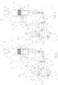
- Figure 1 is an entirely schematic view, representing the various components involved in the counting and unloading of the pharmaceutical articles into a respective container; clearly the unloading mouth will be arranged in such a way that the relative exit opening is located at the mouth of the container to be filled.
- the productivity i.e. the number of containers that are filled in the time unit, or machine cycle, is influenced by the modalities with which the conveyor transfers the pharmaceutical articles to the end thereof, for the articles to fall into the descent channels of the counting machine.
- the increase in the operating velocity of the conveyor has not been found to be an effective method for the aims of increasing productivity.
- Another method at present used in seeking to increase productivity i.e. the number of containers filled in the time unit (or machine cycle) involves using two or more conveyors and therefore two or more respective counting machines arranged flanked to one another, such as for example illustrated in figure 1 , in which various conveyors are illustrated (V, V1, V2, V3, V4, V5) as well as respective six counting machines (A, A10, A20, A30, A40, A50), for example of the type as described above.
- the conveying line (L) of the containers (F) to be filled comprises a spacing member (CD) of the containers (F), for example in the form of a screw conveyor, which is dimensioned and configured to space the containers (F) away from one another by a reciprocal distance corresponding to the distance between the various unloading mouths (BS, BS1, BS2, BS3, BS4, BS5) used for receiving the counted articles counted by the counting machines (A, A10, A20, A30, A40, A50) and for unloading them into the containers (F).
- BS various unloading mouths
- a procedure of this type for carrying out the filling of containers with a series of counting machines arranged flanked to one another can to some extent enable obtaining an increase in productivity, but presents some drawbacks.
- the unloading of the counted articles in the predetermined number by the various unloading mouths in the respective containers may not occur contemporaneously.
- This situation thus represents a limit in the search to further increase the productivity in filling the containers with counted articles in un predetermined number by counting machines arranged flanked to one another, with the respective unloading mouths flanked and aligned above the conveying line of the containers to be filled.
- counting machines that are made in such a way as to comprise two or more accumulation chambers internally of which the counted articles are accumulated falling from the respective chute channels, and thus having two or more respective unloading mouths arranged inferiorly of the respective accumulation chambers for unloading the counted articles in the predetermined number into respective containers positioned and stopped beneath the unloading mouths by a conveying line of containers.
- An aim of the present invention is therefore to provide an apparatus for moving containers to be filled with a predetermined number of articles, for example pharmaceutical articles, which have been counted by counting machines and which are unloaded by respective unloading mouths of the counting machines arranged flanked to one another, able to obviate the drawbacks present in the prior art and as previously mentioned.
- an aim of the present invention is to provide an apparatus which enables moving, and therefore supplying and making available, containers already filled with the predetermined number of articles unloaded from the respective unloading mouths of counting machines, without having to wait for remaining other containers arranged beneath respective other unloading mouths to have internally received the predetermined number of counted articles.
- the above aims are attained with an apparatus for moving containers to be filled with a predetermined number of articles which have been counted by counting machines and unloaded from respective unloading mouths of the counting machines according to the contents of the claims.
- reference numeral (100) denotes the apparatus of the present invention in its entirety.
- the apparatus (100) is realised to carry out the movement of containers, for example bottles, to be filled with a predetermined number of articles, such as, for example pharmaceutical articles, which have been counted by counting machines having one or more unloading mouths (M), with the unloading mouths (M) of the counting machines being arranged flanked to one another in an unloading area (Z) in order for the articles to be released and unloaded, once they have been counted into the predetermined number in order to be inserted in respective containers.
- a predetermined number of articles such as, for example pharmaceutical articles
- the apparatus (100) of the invention is preferably and advantageously applied, in case where the unloading mouths (M) of the counting machines are arranged flanked to one another, and aligned along a common alignment direction, with each comprising a lower opening (M1) (as for example schematically illustrated in figure 12A ) for releasing and unloading the counted articles in the predetermined number.
- the apparatus (100) is in any case also utilisable in various situations and cases, in which the unloading mouths of the counting machines are not aligned along a common alignment direction, but may even be arranged offset to one another.
- the apparatus (100) comprises (see for example figures 2 and 3 ):
- the movement station (80) is made in such a way as to comprise a series of translation units (1, 2) of containers (for example, in the preferred embodiment illustrated in the figures of the drawings, they are two in number, and visible schematically in figure 2 ) for translating the containers onto the support plane (81), wherein the translation units (1, 2) are arranged and configured to be activatable independently of one another, in order each to translate respective containers onto the support plane (81) and with respect to a respective unloading mouth (M) of the counting machines.
- a series of translation units (1, 2) of containers for example, in the preferred embodiment illustrated in the figures of the drawings, they are two in number, and visible schematically in figure 2 ) for translating the containers onto the support plane (81), wherein the translation units (1, 2) are arranged and configured to be activatable independently of one another, in order each to translate respective containers onto the support plane (81) and with respect to a respective unloading mouth (M) of the counting machines.
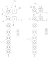
- each translation unit (1, 2) (illustrated in a preferred embodiment in figures from 4 to 9) of the series of translation units (1, 2) is configured and activatable to translate a respective empty container (E), which has been positioned in the first stop position (P1) by the positioning means (91), from the first stop position (P1) to a second stop position (P2) on the support plane (81) in which the empty container (E) is positioned and arranged with a respective opening beneath a respective unloading mouth (M) of the unloading mouths (M) of the counting machines in such a way as to be able to receive internally thereof articles unloaded from the unloading mouth (M) once they have been counted into the predetermined number (see for example figure 2, figure 3 or the sequence illustrated in figures 4 and 5 , or the sequence illustrated in figures 12A and 12B ).
- each translation unit (1, 2) as soon as the empty container (E) has been filled with the predetermined number of articles unloaded from the respective unloading mouth (M), becoming thus a full container (T) containing the predetermined number of articles, is configured in such a way as to carry out successive activation cycles wherein in each activation cycle the translation unit is activatable (see for example the sequence illustrated in figures from 6 to 9, or figures 12C, 12D ):
- the apparatus in the movement station located in the unloading area of the articles, is provided with a series of translation units, each activatable independently of one another, and each of which is predisposed and configured to translate respective containers, positioning them, time by time, beneath a respective single unloading mouth of the unloading mouths of the counting machines in order to permit filling thereof, it is possible to immediately free up the unloading mouths that have already carried out the count and unloading of the articles, positioning beneath them successive empty containers to be filled, without having to wait for all the remaining counting machines to have also completed the counting and unloading thereof, as occurs in the prior art, as evidenced in the foregoing.
- Each translation unit (1, 2) of the series of translation units (1, 2) is realised in such a way as to comprise (see for example figures 4, 5 , 6, 7 , 8, 9 ):
- the first kinematism (11) and the second kinematism (21) are configured and reciprocally arranged, and the first drive shaft (13) and the second drive shaft (23) are reciprocally arranged in respective first angular positions (z1, z2), with respect to the frame (U) present in the movement station (80), in such a way that (see for example figure 4 ): the first pusher wall (10) and the second pusher wall (20) are positioned in a first raised position (S1) with respect to the support plane (81), with the first pusher wall (10) arranged upstream of the first stop position (P1) of the empty containers (E) with respect to the respective unloading mouth (M) of the unloading mouths (M) of the counting machines and with the second pusher wall (20) arranged between the first stop position (P1) and the second stop position (P2), to enable the positioning means (91) to position empty containers (E) in the first stop position (P1), between the first pusher wall (10) and the second pusher wall (20).
- each translation unit (1, 2) is able to transfer a container from the second stop position (P2) to the third position (P3), as soon as the empty container (E) has been filled with the predetermined number of articles unloaded from the respective unloading mouth, therefore becoming a full container, and, at the same time, transferring an empty container from the first stop position (P1) to the second stop position (P2) beneath the unloading mouth, for the successive filling thereof.
- each translation unit (1, 2) of the series of translation units (1, 2) comprises:
- the third kinematism (31) is configured and arranged with respect to the second kinematism (21) and to the frame (U) of the movement station (80) in such a way that:
- the support plane (81) of the movement station (80) comprises, for each translation unit (1, 2), a respective groove (82) (see for example figure 2 ).
- the support plane (81) of the movement station (80) further comprises, for each translation unit (1, 2), respective through-slots (not illustrated in detail) for enabling passage of the abutment elements (32) when translated from the lowered configuration (O1) to the raised configuration (O2), and vice versa.
- the first kinematism (11), the second kinematism (12) and the third kinematism (31) of each translation unit (1, 2) can be realised as described in the following, as is illustrated in detail in figures from 4 to 9.
- the first kinematism (11) comprises:
- the second kinematism (21) in turn comprises:
- the levers making up the first kinematism (11) and the levers making up the second kinematism (21), as described above and listed, are configured, dimensioned and reciprocally arranged, as is illustrated in figures from 4 to 9, in such a way as to enable the positioning of the first kinematism (11) and of the second kinematism (12), with the first drive shaft (13) arranged in the respective first angular position (z1) and with the second drive shaft (23) arranged in the respective second angular position (z2), in such a way that the first pusher wall (10) and the second pusher wall (20) are arranged and positioned in the first raised position (S1), as previously described and as illustrated in figure 4 .
- the levers making up the first kinematism (11) and the levers making up the second kinematism (21), as described above and listed, are further configured, dimensioned and reciprocally arranged in such a way as to enable, following the cyclical driving in rotation of the first drive shaft (13) and the second drive shaft (23), with respect to the respective rotation axes (A1) and (A2), between the respective first (z1, z2) and second (z3, z4) angular positions, the movement of the first kinematism (11) and the second kinematism (21) for the movement of the first pusher wall (10) and the second pusher wall (20) as described in the foregoing, and as is illustrated in figures from 5 to 9, for the translation of the empty containers from the first stop position (P1) to the second stop position (P2) and the full containers (T) from the second stop position (P2) to the third position (P3).
- the third kinematism (31) in turn comprises:
- the levers making up the third kinematism (31), as described above and listed, are further configured, dimensioned and reciprocally arranged in such a way as to enable, following the cyclical driving in rotation of the second drive shaft (23), with respect to the respective rotation axis (A2), between the respective first (z2) and second (z4) angular position, the movement of the third kinematism (31) for the movement of the abutting elements (32) as previously mentioned, from the respective first lowered configuration (O1) to the second raised configuration (O2), and vice versa, as is illustrated in figures from 5 to 9.
- the apparatus (100) can be made in such a way as to comprise, for each translation unit (1, 2) of the movement station (80), a first loading cell (51) arranged beneath the first stop position (P1) in which the empty containers (E) are positioned, a second loading cell (52) arranged beneath the second stop position (P2) in which the empty containers (E) to be filled are positioned with a predetermined number of articles unloaded by a respective unloading mouth (M) of the counting machines (see for example figure 10 ).
- the first loading cell (51) is vertically translatable between a respective lowered station (PA) and a respective raised station (PS) with respect to the support plane (81), wherein the first loading cell (51) is positioned beneath, and is in contact with, each empty container (E) which, time by time, is positioned by the positioning means (91) in the first stop position (P1), so as to detect the weight of the empty containers.
- PA lowered station
- PS raised station
- the second loading cell (52) is vertically translatable between a respective lowered station (TA) and a respective raised station (PS) with respect to the support plane (81), wherein the second loading cell (52) is positioned beneath, and in contact with, each full container (T), so as to detect the weight of the full containers.
- the apparatus (100) can comprise, for each translation unit (1, 2) of the movement station (80), a single loading cell (61) positioned beneath the second stop position (P2) in which the empty containers (E) to be filled are positioned with a predetermined number of articles unloaded by a respective unloading mouth (M) of the counting machines to become full containers (T).
- the single loading cell (61) is translatable vertically from a respective first lowered station (VA) to a respective second raised station (VS) each time an empty container (E) is positioned in the second stop position (P2) in order to be positioned in contact with the empty container (E) so as to detect the weight of the empty container (E), and then to detect the weight of the container when it has received internally thereof a predetermined number of unloaded articles from a respective unloading mouth (M), becoming a full container (T), so as to detect the weight of the full container (T).
- independent actuators can be provided, or further kinematisms connected to the first and/or second kinematism of each translation unit can be provided.
- the infeeding means (90), as for example illustrated in figure 3 can comprise a conveying line (92) having a transport branch for the transport of the empty containers (E) in an advancement direction (90L) which extends towards an edge of the support plane (81) of the infeeding station (80).
- the positioning means (91) of the empty containers (E) in the first stop position (P1) can be made in such a way as to comprise a screw conveyor (93), arranged consecutively to the conveying line (92), having a series of seats, for receiving internally thereof the empty containers (E) infed from the conveying line (92), distanced from one another by a pitch corresponding to the distance existing between the unloading mouths (M) of the counting machines in such a way as to position single empty containers (E) on the support plane (81) in front of and aligned with a respective unloading mouth (M).
- the apparatus (100) can also comprise a transfer line (95) (see figure 3 once more) arranged on the opposite side, and parallel, to the conveying line (92), with respect to the support plane (81), having a transport branch for the transport of the full containers (T) translated into the third position (P3) towards successive work stations.
- a transfer line (95) (see figure 3 once more) arranged on the opposite side, and parallel, to the conveying line (92), with respect to the support plane (81), having a transport branch for the transport of the full containers (T) translated into the third position (P3) towards successive work stations.
Landscapes
- Engineering & Computer Science (AREA)
- Mechanical Engineering (AREA)
- Quality & Reliability (AREA)
- Intermediate Stations On Conveyors (AREA)
- Attitude Control For Articles On Conveyors (AREA)
- Control Of Conveyors (AREA)
Applications Claiming Priority (1)
| Application Number | Priority Date | Filing Date | Title |
|---|---|---|---|
| IT102023000022842A IT202300022842A1 (it) | 2023-10-31 | 2023-10-31 | Apparecchiatura per movimentare contenitori da riempire con un numero prefissato di articoli che sono stati conteggiati da macchine contatrici e che vengono scaricati da rispettive bocche di scarico delle macchine contatrici |
Publications (2)
| Publication Number | Publication Date |
|---|---|
| EP4570673A2 true EP4570673A2 (de) | 2025-06-18 |
| EP4570673A3 EP4570673A3 (de) | 2025-08-20 |
Family
ID=89983118
Family Applications (1)
| Application Number | Title | Priority Date | Filing Date |
|---|---|---|---|
| EP24209895.2A Pending EP4570673A3 (de) | 2023-10-31 | 2024-10-30 | Vorrichtung zum bewegen von behältern, die mit einer vorbestimmten anzahl von mit zählmaschinen abzählenden und mit zugehörigen entladeöffnungen der zählmaschinen abgeladenen artikeln gefüllt werden |
Country Status (2)
| Country | Link |
|---|---|
| EP (1) | EP4570673A3 (de) |
| IT (1) | IT202300022842A1 (de) |
Family Cites Families (3)
| Publication number | Priority date | Publication date | Assignee | Title |
|---|---|---|---|---|
| US3682207A (en) * | 1970-10-23 | 1972-08-08 | Brown Int Corp | Container filling apparatus |
| KR20120136929A (ko) * | 2011-06-10 | 2012-12-20 | (주)스마트코퍼레이션 | 용기밀봉장치 |
| KR101430555B1 (ko) * | 2012-09-28 | 2014-09-23 | 주식회사 코사파트너스 | 정제 또는 캡슐의 자동 소분포장 장치 및 이를 이용한 자동 계수 및 소분포장 방법 |
-
2023
- 2023-10-31 IT IT102023000022842A patent/IT202300022842A1/it unknown
-
2024
- 2024-10-30 EP EP24209895.2A patent/EP4570673A3/de active Pending
Also Published As
| Publication number | Publication date |
|---|---|
| IT202300022842A1 (it) | 2025-05-01 |
| EP4570673A3 (de) | 2025-08-20 |
Similar Documents
| Publication | Publication Date | Title |
|---|---|---|
| US12077333B2 (en) | Apparatuses and methods for tamping the contents of a container | |
| US4627215A (en) | Apparatus for charging receptacles with stacked, flat items | |
| US4901504A (en) | Filling and casing system | |
| US7481309B2 (en) | Method of separating, synchronizing and compacting packed groups of articles | |
| EP1278691B1 (de) | Vorrichtung und verfahren zum sammeln und verpacken von produkteinheiten | |
| US20050188658A1 (en) | Packaging machine and method | |
| EP2499069B1 (de) | Sortiermaschine für behälter und zugehöriges verfahren | |
| US6755008B2 (en) | Method and apparatus for the packaging of articles | |
| EP2671807B1 (de) | Vorrichtung zum Übertragen pharmazeutischer Produkte von einem Zähler zu kontinuerlich geförderten Behältern | |
| CA2624752A1 (en) | Robotic multi-product case-packing system | |
| US20060191238A1 (en) | Method and device for packing tubes | |
| CN112752722B (zh) | 用于传送产品的设备和方法 | |
| AU649286B2 (en) | Collating apparatus | |
| JP2002029516A (ja) | ブリスタリング装置においてブリスタバンド上で余った製品を回収する装置 | |
| AU2006236987B2 (en) | Packaging machine | |
| CN219008182U (zh) | 一种多头秤定量包装生产线的工位下料机 | |
| EP3971130A1 (de) | Maschine zum füllen von behältern mit flüssigkeit und entsprechendes füllverfahren | |
| US5862649A (en) | Method and device for packaging cans or tubes | |
| US5020304A (en) | Method and apparatus for loading and stacking crates | |
| CN107814176B (zh) | 自动理料装置 | |
| CN210942418U (zh) | 一种滴眼液包装联动系统 | |
| US4930289A (en) | Machine for packing tablets into tubes | |
| US3877199A (en) | Frankfurter packaging machine | |
| CN214139224U (zh) | 玻璃盘全检机转盘式计数包装机 | |
| WO2025062272A1 (en) | A method for filling containers with a predetermined number of articles counted by counting machines and unloaded from respective unloading mouths of the counting machines |
Legal Events
| Date | Code | Title | Description |
|---|---|---|---|
| PUAI | Public reference made under article 153(3) epc to a published international application that has entered the european phase |
Free format text: ORIGINAL CODE: 0009012 |
|
| STAA | Information on the status of an ep patent application or granted ep patent |
Free format text: STATUS: THE APPLICATION HAS BEEN PUBLISHED |
|
| AK | Designated contracting states |
Kind code of ref document: A2 Designated state(s): AL AT BE BG CH CY CZ DE DK EE ES FI FR GB GR HR HU IE IS IT LI LT LU LV MC ME MK MT NL NO PL PT RO RS SE SI SK SM TR |
|
| PUAL | Search report despatched |
Free format text: ORIGINAL CODE: 0009013 |
|
| AK | Designated contracting states |
Kind code of ref document: A3 Designated state(s): AL AT BE BG CH CY CZ DE DK EE ES FI FR GB GR HR HU IE IS IT LI LT LU LV MC ME MK MT NL NO PL PT RO RS SE SI SK SM TR |
|
| RIC1 | Information provided on ipc code assigned before grant |
Ipc: B65B 1/06 20060101AFI20250715BHEP Ipc: B65B 43/48 20060101ALI20250715BHEP Ipc: B65B 57/20 20060101ALI20250715BHEP Ipc: B65B 1/32 20060101ALI20250715BHEP Ipc: B65B 35/20 20060101ALI20250715BHEP Ipc: B65B 65/02 20060101ALI20250715BHEP |