EP4570480A1 - Verfahren zur herstellung eines verbundenen objekts, verbundenes objekt und elektrisches/elektronisches bauelement - Google Patents
Verfahren zur herstellung eines verbundenen objekts, verbundenes objekt und elektrisches/elektronisches bauelement Download PDFInfo
- Publication number
- EP4570480A1 EP4570480A1 EP23852275.9A EP23852275A EP4570480A1 EP 4570480 A1 EP4570480 A1 EP 4570480A1 EP 23852275 A EP23852275 A EP 23852275A EP 4570480 A1 EP4570480 A1 EP 4570480A1
- Authority
- EP
- European Patent Office
- Prior art keywords
- resin
- joined object
- thermoplastic film
- base material
- film
- Prior art date
- Legal status (The legal status is an assumption and is not a legal conclusion. Google has not performed a legal analysis and makes no representation as to the accuracy of the status listed.)
- Pending
Links
Images


Classifications
-
- B—PERFORMING OPERATIONS; TRANSPORTING
- B29—WORKING OF PLASTICS; WORKING OF SUBSTANCES IN A PLASTIC STATE IN GENERAL
- B29C—SHAPING OR JOINING OF PLASTICS; SHAPING OF MATERIAL IN A PLASTIC STATE, NOT OTHERWISE PROVIDED FOR; AFTER-TREATMENT OF THE SHAPED PRODUCTS, e.g. REPAIRING
- B29C65/00—Joining or sealing of preformed parts, e.g. welding of plastics materials; Apparatus therefor
- B29C65/70—Joining or sealing of preformed parts, e.g. welding of plastics materials; Apparatus therefor by moulding
-
- B—PERFORMING OPERATIONS; TRANSPORTING
- B29—WORKING OF PLASTICS; WORKING OF SUBSTANCES IN A PLASTIC STATE IN GENERAL
- B29C—SHAPING OR JOINING OF PLASTICS; SHAPING OF MATERIAL IN A PLASTIC STATE, NOT OTHERWISE PROVIDED FOR; AFTER-TREATMENT OF THE SHAPED PRODUCTS, e.g. REPAIRING
- B29C70/00—Shaping composites, i.e. plastics material comprising reinforcements, fillers or preformed parts, e.g. inserts
- B29C70/68—Shaping composites, i.e. plastics material comprising reinforcements, fillers or preformed parts, e.g. inserts by incorporating or moulding on preformed parts, e.g. inserts or layers, e.g. foam blocks
- B29C70/681—Component parts, details or accessories; Auxiliary operations
- B29C70/682—Preformed parts characterised by their structure, e.g. form
-
- B—PERFORMING OPERATIONS; TRANSPORTING
- B29—WORKING OF PLASTICS; WORKING OF SUBSTANCES IN A PLASTIC STATE IN GENERAL
- B29C—SHAPING OR JOINING OF PLASTICS; SHAPING OF MATERIAL IN A PLASTIC STATE, NOT OTHERWISE PROVIDED FOR; AFTER-TREATMENT OF THE SHAPED PRODUCTS, e.g. REPAIRING
- B29C45/00—Injection moulding, i.e. forcing the required volume of moulding material through a nozzle into a closed mould; Apparatus therefor
- B29C45/14—Injection moulding, i.e. forcing the required volume of moulding material through a nozzle into a closed mould; Apparatus therefor incorporating preformed parts or layers, e.g. injection moulding around inserts or for coating articles
- B29C45/14639—Injection moulding, i.e. forcing the required volume of moulding material through a nozzle into a closed mould; Apparatus therefor incorporating preformed parts or layers, e.g. injection moulding around inserts or for coating articles for obtaining an insulating effect, e.g. for electrical components
-
- B—PERFORMING OPERATIONS; TRANSPORTING
- B29—WORKING OF PLASTICS; WORKING OF SUBSTANCES IN A PLASTIC STATE IN GENERAL
- B29C—SHAPING OR JOINING OF PLASTICS; SHAPING OF MATERIAL IN A PLASTIC STATE, NOT OTHERWISE PROVIDED FOR; AFTER-TREATMENT OF THE SHAPED PRODUCTS, e.g. REPAIRING
- B29C45/00—Injection moulding, i.e. forcing the required volume of moulding material through a nozzle into a closed mould; Apparatus therefor
- B29C45/14—Injection moulding, i.e. forcing the required volume of moulding material through a nozzle into a closed mould; Apparatus therefor incorporating preformed parts or layers, e.g. injection moulding around inserts or for coating articles
- B29C45/14778—Injection moulding, i.e. forcing the required volume of moulding material through a nozzle into a closed mould; Apparatus therefor incorporating preformed parts or layers, e.g. injection moulding around inserts or for coating articles the article consisting of a material with particular properties, e.g. porous, brittle
- B29C45/14811—Multilayered articles
-
- B—PERFORMING OPERATIONS; TRANSPORTING
- B29—WORKING OF PLASTICS; WORKING OF SUBSTANCES IN A PLASTIC STATE IN GENERAL
- B29C—SHAPING OR JOINING OF PLASTICS; SHAPING OF MATERIAL IN A PLASTIC STATE, NOT OTHERWISE PROVIDED FOR; AFTER-TREATMENT OF THE SHAPED PRODUCTS, e.g. REPAIRING
- B29C65/00—Joining or sealing of preformed parts, e.g. welding of plastics materials; Apparatus therefor
- B29C65/02—Joining or sealing of preformed parts, e.g. welding of plastics materials; Apparatus therefor by heating, with or without pressure
-
- B—PERFORMING OPERATIONS; TRANSPORTING
- B29—WORKING OF PLASTICS; WORKING OF SUBSTANCES IN A PLASTIC STATE IN GENERAL
- B29C—SHAPING OR JOINING OF PLASTICS; SHAPING OF MATERIAL IN A PLASTIC STATE, NOT OTHERWISE PROVIDED FOR; AFTER-TREATMENT OF THE SHAPED PRODUCTS, e.g. REPAIRING
- B29C65/00—Joining or sealing of preformed parts, e.g. welding of plastics materials; Apparatus therefor
- B29C65/48—Joining or sealing of preformed parts, e.g. welding of plastics materials; Apparatus therefor using adhesives, i.e. using supplementary joining material; solvent bonding
- B29C65/4805—Joining or sealing of preformed parts, e.g. welding of plastics materials; Apparatus therefor using adhesives, i.e. using supplementary joining material; solvent bonding characterised by the type of adhesives
- B29C65/481—Non-reactive adhesives, e.g. physically hardening adhesives
- B29C65/4815—Hot melt adhesives, e.g. thermoplastic adhesives
-
- B—PERFORMING OPERATIONS; TRANSPORTING
- B29—WORKING OF PLASTICS; WORKING OF SUBSTANCES IN A PLASTIC STATE IN GENERAL
- B29C—SHAPING OR JOINING OF PLASTICS; SHAPING OF MATERIAL IN A PLASTIC STATE, NOT OTHERWISE PROVIDED FOR; AFTER-TREATMENT OF THE SHAPED PRODUCTS, e.g. REPAIRING
- B29C65/00—Joining or sealing of preformed parts, e.g. welding of plastics materials; Apparatus therefor
- B29C65/48—Joining or sealing of preformed parts, e.g. welding of plastics materials; Apparatus therefor using adhesives, i.e. using supplementary joining material; solvent bonding
- B29C65/50—Joining or sealing of preformed parts, e.g. welding of plastics materials; Apparatus therefor using adhesives, i.e. using supplementary joining material; solvent bonding using adhesive tape, e.g. thermoplastic tape; using threads or the like
-
- B—PERFORMING OPERATIONS; TRANSPORTING
- B29—WORKING OF PLASTICS; WORKING OF SUBSTANCES IN A PLASTIC STATE IN GENERAL
- B29C—SHAPING OR JOINING OF PLASTICS; SHAPING OF MATERIAL IN A PLASTIC STATE, NOT OTHERWISE PROVIDED FOR; AFTER-TREATMENT OF THE SHAPED PRODUCTS, e.g. REPAIRING
- B29C66/00—General aspects of processes or apparatus for joining preformed parts
- B29C66/70—General aspects of processes or apparatus for joining preformed parts characterised by the composition, physical properties or the structure of the material of the parts to be joined; Joining with non-plastics material
- B29C66/74—Joining plastics material to non-plastics material
- B29C66/742—Joining plastics material to non-plastics material to metals or their alloys
-
- B—PERFORMING OPERATIONS; TRANSPORTING
- B29—WORKING OF PLASTICS; WORKING OF SUBSTANCES IN A PLASTIC STATE IN GENERAL
- B29C—SHAPING OR JOINING OF PLASTICS; SHAPING OF MATERIAL IN A PLASTIC STATE, NOT OTHERWISE PROVIDED FOR; AFTER-TREATMENT OF THE SHAPED PRODUCTS, e.g. REPAIRING
- B29C69/00—Combinations of shaping techniques not provided for in a single one of main groups B29C39/00 - B29C67/00, e.g. associations of moulding and joining techniques; Apparatus therefore
-
- B—PERFORMING OPERATIONS; TRANSPORTING
- B29—WORKING OF PLASTICS; WORKING OF SUBSTANCES IN A PLASTIC STATE IN GENERAL
- B29C—SHAPING OR JOINING OF PLASTICS; SHAPING OF MATERIAL IN A PLASTIC STATE, NOT OTHERWISE PROVIDED FOR; AFTER-TREATMENT OF THE SHAPED PRODUCTS, e.g. REPAIRING
- B29C70/00—Shaping composites, i.e. plastics material comprising reinforcements, fillers or preformed parts, e.g. inserts
- B29C70/68—Shaping composites, i.e. plastics material comprising reinforcements, fillers or preformed parts, e.g. inserts by incorporating or moulding on preformed parts, e.g. inserts or layers, e.g. foam blocks
- B29C70/72—Encapsulating inserts having non-encapsulated projections, e.g. extremities or terminal portions of electrical components
-
- B—PERFORMING OPERATIONS; TRANSPORTING
- B29—WORKING OF PLASTICS; WORKING OF SUBSTANCES IN A PLASTIC STATE IN GENERAL
- B29C—SHAPING OR JOINING OF PLASTICS; SHAPING OF MATERIAL IN A PLASTIC STATE, NOT OTHERWISE PROVIDED FOR; AFTER-TREATMENT OF THE SHAPED PRODUCTS, e.g. REPAIRING
- B29C45/00—Injection moulding, i.e. forcing the required volume of moulding material through a nozzle into a closed mould; Apparatus therefor
- B29C45/14—Injection moulding, i.e. forcing the required volume of moulding material through a nozzle into a closed mould; Apparatus therefor incorporating preformed parts or layers, e.g. injection moulding around inserts or for coating articles
- B29C45/14598—Coating tubular articles
- B29C45/14622—Lining the inner or outer surface of tubular articles
-
- B—PERFORMING OPERATIONS; TRANSPORTING
- B29—WORKING OF PLASTICS; WORKING OF SUBSTANCES IN A PLASTIC STATE IN GENERAL
- B29C—SHAPING OR JOINING OF PLASTICS; SHAPING OF MATERIAL IN A PLASTIC STATE, NOT OTHERWISE PROVIDED FOR; AFTER-TREATMENT OF THE SHAPED PRODUCTS, e.g. REPAIRING
- B29C53/00—Shaping by bending, folding, twisting, straightening or flattening; Apparatus therefor
- B29C53/56—Winding and joining, e.g. winding spirally
-
- B—PERFORMING OPERATIONS; TRANSPORTING
- B29—WORKING OF PLASTICS; WORKING OF SUBSTANCES IN A PLASTIC STATE IN GENERAL
- B29K—INDEXING SCHEME ASSOCIATED WITH SUBCLASSES B29B, B29C OR B29D, RELATING TO MOULDING MATERIALS OR TO MATERIALS FOR MOULDS, REINFORCEMENTS, FILLERS OR PREFORMED PARTS, e.g. INSERTS
- B29K2063/00—Use of EP, i.e. epoxy resins or derivatives thereof, as moulding material
-
- B—PERFORMING OPERATIONS; TRANSPORTING
- B29—WORKING OF PLASTICS; WORKING OF SUBSTANCES IN A PLASTIC STATE IN GENERAL
- B29K—INDEXING SCHEME ASSOCIATED WITH SUBCLASSES B29B, B29C OR B29D, RELATING TO MOULDING MATERIALS OR TO MATERIALS FOR MOULDS, REINFORCEMENTS, FILLERS OR PREFORMED PARTS, e.g. INSERTS
- B29K2705/00—Use of metals, their alloys or their compounds, for preformed parts, e.g. for inserts
-
- B—PERFORMING OPERATIONS; TRANSPORTING
- B29—WORKING OF PLASTICS; WORKING OF SUBSTANCES IN A PLASTIC STATE IN GENERAL
- B29K—INDEXING SCHEME ASSOCIATED WITH SUBCLASSES B29B, B29C OR B29D, RELATING TO MOULDING MATERIALS OR TO MATERIALS FOR MOULDS, REINFORCEMENTS, FILLERS OR PREFORMED PARTS, e.g. INSERTS
- B29K2995/00—Properties of moulding materials, reinforcements, fillers, preformed parts or moulds
- B29K2995/0037—Other properties
- B29K2995/0039—Amorphous
-
- B—PERFORMING OPERATIONS; TRANSPORTING
- B29—WORKING OF PLASTICS; WORKING OF SUBSTANCES IN A PLASTIC STATE IN GENERAL
- B29L—INDEXING SCHEME ASSOCIATED WITH SUBCLASS B29C, RELATING TO PARTICULAR ARTICLES
- B29L2031/00—Other particular articles
- B29L2031/34—Electrical apparatus, e.g. sparking plugs or parts thereof
- B29L2031/3406—Components, e.g. resistors
Definitions
- the present invention relates to a method for producing a joined object in which dissimilar materials are firmly joined, a joined object, and an electric/electronic component.
- Multi-materialization is a method for reducing the weight and increasing the strength of materials by using materials with different functions and materials (hereinafter, referred to as dissimilar materials) in combination.
- dissimilar materials materials with different functions and materials
- a technique for firmly joining dissimilar materials is indispensable.
- An example of a product using a component requiring multi-materialization is a capacitor.
- the capacitor is provided with at least an insulator and an electrode body inside an outer container.
- a positive electrode body and a negative electrode body extend from a through hole of the outer container in order to exchange electricity with the outside.
- a method of sealing a gap between the electrode body and the through hole by using a resin material as a sealing material is adopted.
- electronic devices often cause malfunctions due to slight moisture or powder dust, and thus high adhesiveness (leakage resistance) is required for the sealing portion.
- a technique is known in which a resin material serving as a sealing material is used to seal the periphery of the metal terminals by insert molding such as injection molding.
- insert molding such as injection molding.
- the resin material is sealed to the metal by insert molding, there is a risk of leakage from the gap.
- a resin material is sealed so as to cover the periphery of a metal terminal or the like, more excellent leakage resistance is required.
- a method for sealing the metal terminal or the like with a resin material for example, a method in which a liquid adhesive or varnish is applied to the metal terminal and then the metal terminal is sealed with the resin material by insert molding has been studied.
- a technique is known in which a primer layer is provided by applying an in-situ polymerization type composition to an electrode body and polymerizing the composition, and then a sealing portion is formed (PTL 1).
- a technique is known in which an external terminal is immersed in a bath filled with a cationic epoxy resin-based electrodeposition coating material, a terminal adhesive layer is provided by energizing the external terminal, and then a sealing member is formed (PTL 2).
- the technique of applying the liquid adhesive may take time for adhesion, and problems such as pot life (usable time) and labor are likely to occur.
- the leakage resistance may be impaired due to an insufficient coating amount or an uneven coating operation, or a contamination risk may occur due to an excessive coating amount, resulting in poor workability.
- thermosetting adhesive when the metal terminal is repeatedly exposed to a high temperature and a low temperature (during a thermal cycle), the metal terminal and the sealing resin are displaced due to a difference in linear expansion coefficient between the metal terminal and the sealing resin, and a stress is applied to the adhesive layer. Then, the adhesive layer cannot relax the stress and is peeled off, so that leakage is likely to occur. This is because the thermosetting adhesive layer does not have thermoplasticity and is rapidly broken when reaching a plastic deformation region.
- the adhesive force with the sealing material can be increased, but a gap is likely to occur between the roughened surface of the electrode body and the sealing material, and there is a concern that the leakage resistance will be insufficient.
- peeling is likely to occur.
- an object of the present invention is to provide a method for producing a joined object in which a joining process time is short, dissimilar materials are firmly joined, and leakage resistance is excellent, a joined object, and an electric/electronic component.
- the present inventors have found that the above-mentioned problems can be solved by winding a predetermined film around a base material, joining the film to the base material, and then sealing the film with a resin.
- the present invention is as follows.
- the present invention it is possible to provide a method for producing a joined object in which the joining process time is short, dissimilar materials are firmly joined, and leakage resistance is excellent, a joined object, and an electric/electronic component.
- joining means joining objects to each other, and adhesion and welding are subordinate concepts thereof.
- adhesion means that two adherends (objects to be adhered) are brought into a joined state via an organic material (thermosetting resin or thermoplastic resin) such as a tape or an adhesive.
- welding means that the surface of a thermoplastic resin or the like is melted by heat and cooled to cause entanglement due to molecular diffusion, thereby forming a joined state.
- the "adhesive property” means a property having an adhesive strength capable of connecting an object to another object.
- the "joined object obtained by joining in this order” means that the members are spatially joined in this order.
- the "joining process time” means a time from a start point to an end point, where the start point is the time of contact between the base material and the film constituting the joined object, and the end point is the time of completion of the production of the joined object.
- the joining process time includes a step of winding the film around the base material, and a time required to join and seal the resin by insert molding.
- the method for producing a joined object of the present embodiment is a method for producing a joined object obtained by joining a columnar base material A, a thermoplastic film B, and a resin C in this order, the method including sequentially performing:
- thermoplastic film B By providing the thermoplastic film B between the columnar base material A and the resin C which is a sealing material, the columnar base material A and the resin C are firmly joined. Furthermore, since the thermoplastic film B can be wound around the columnar base material A, it can be said that this operation is more effective than applying a liquid joining agent or the like in shortening the joining process. In addition, by using the thermoplastic film B having a uniform thickness, as compared with the case where a liquid joining agent or the like is applied, a non-uniform portion such as an uncoated portion or sagging does not occur, and excellent leakage resistance can be exhibited.
- thermoplastic resin that has completed a chemical reaction such as polymerization between the columnar base material A and the resin C, it is possible to perform a rapid curing that utilizes a phase change between a solid and a liquid, and it is possible to shorten the joining process.
- thermoplastic resin in the form of a film shape as compared with the case of applying a liquid joining agent having an irregular shape, there is no complication in handling the liquid, and the joining process time may be shortened.
- thermoplastic resin has a thermoplasticity even at a high temperature, it is possible to relax the stress, and it is possible to reset the stress for each cycle during a thermal cycle, and to prevent peeling. Therefore, by using the thermoplastic film B, plastic deformation can be performed, and the stress can be effectively relaxed, so that a joined object which is hardly peeled during the thermal cycle and has excellent leakage resistance can be obtained. Further, since the resin C is softened when the joined object is exposed to a high temperature, the stress can be more effectively relaxed, and therefore the leakage resistance is excellent.
- thermoplastic film B in a case where an amorphous thermoplastic film B is used as the thermoplastic film B, the film is less likely to undergo a rapid decrease in viscosity during heating, and thus the shape for maintaining the leakage resistance can be maintained when the joined object is exposed to a high temperature.
- thermoplastic film B is wound around at least a part of an outer periphery of the columnar base material A in a peripheral direction.
- the "at least a part of an outer periphery” means at least a part of the columnar base material A in the major axis direction.
- the term “winding” means that the thermoplastic film B is wound one round or more than one round in the peripheral direction of the columnar base material A.
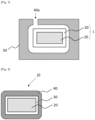
- step 1 One example of the embodiment of the step 1 will be described with reference to Fig. 1 and Fig. 2 .
- Fig. 1 is a front view showing an example of an embodiment of a film-attached base material.
- Fig. 2 is an illustrative view of the step 1 in a cross section of a B-B' cut surface parallel to the Y axis of the film-attached base material of Fig. 1 .
- the thermoplastic film B 30 may be wound around the outer periphery of at least a part of the columnar base material A 20.
- a part of the columnar base material A 20 may have a non-adhering portion a of the thermoplastic film B 30, may not have the non-adhering portion a, or may have the non-adhering portion a only on one end of the columnar base material A 20. It is preferable that the columnar base material A 20 has the non-adhering portion a at both ends.
- thermoplastic film B 30 is wound around the outer periphery of the columnar base material A 20 in the peripheral direction.
- the thermoplastic film B 30 may be wound so that the thermoplastic film B 30 continuously covers the outer periphery of the columnar base material A 20. Since the thermoplastic film B 30 is wound one round or more than one round in the peripheral direction of the columnar base material A 20, there is no gap at both end sides of the wound thermoplastic film B 30, the sealing property becomes high, and excellent leakage resistance can be exhibited.
- thermoplastic film B may have tackiness. From the viewpoint of ease of handling, it is preferable that the thermoplastic film B has tackiness and is temporarily fixed to the columnar base material A.
- thermoplastic film B may be temporarily fixed by being wound around the columnar base material A after a pressure-sensitive adhesive is applied to the thermoplastic film B to the extent that the leakage resistance is not impaired.
- a pressure-sensitive adhesive a commercially available product can be used.
- thermoplastic film B After the thermoplastic film B is wound around the outer periphery of the columnar base material A as described above, it is preferable to perform an operation of melting and solidifying the wound thermoplastic film B to join the columnar base material A and the thermoplastic film B.
- thermoplastic film B 30 after the thermoplastic film B 30 is wound around the columnar base material A 20, the thermoplastic film B 30 may be melted and solidified. Since the thermoplastic film B 30 is thermoplastic, as shown in 2-3 of Fig. 2 , the thermoplastic film B 30 is closely adhered to and joined to the columnar base material A 20 without a gap.
- the thermoplastic film B can be melted and solidified by insert-molding the resin C in the next step 2. Therefore, the thermoplastic film B may be melted and solidified by heating in the molding step of the resin C in the step 2 without melting and solidifying the thermoplastic film B in the step 1.
- the columnar base material A and the thermoplastic film B can be more reliably joined and integrated, so that the sealing property can be enhanced, and the leakage resistance can be further improved.
- examples of the method for melting the thermoplastic film B include at least one method selected from the group consisting of contact heating, hot air heating, hot pressing, hot plate welding, infrared heating, ultrasonic welding, vibration welding, and high-frequency induction welding.
- hot pressing or high-frequency induction welding is preferable from the viewpoint of ease of production and shortening of the joining process.
- the heating temperature of the joining surface between the columnar base material A and the thermoplastic film B may be determined in consideration of the heat-resistant temperature of the material of the columnar base material A, and is preferably 100 to 300°C, more preferably 120 to 250°C, and further preferably 150°C to 220°C.
- the thermoplastic film B is efficiently deformed and melted, and effectively wets and spreads on the joining surface, so that a high joining force can be obtained.
- solidification means that the material is solid at ordinary temperature, that is, the material does not have fluidity at 23°C in a non-pressurized state.
- the shape of the columnar base material A is not particularly limited. Examples of the shape of a cross section perpendicular to the length direction of the columnar base material A include a circular shape, a semicircular shape, an elliptical shape, a square shape, a rectangular shape, a triangular shape, and other polygonal shapes.
- the polygonal shape may be a regular polygonal shape or a shape other than the regular polygonal shape.
- the columnar base material A also includes a quadrangular prism (strip) having a rectangular cross section with a large aspect ratio.
- Examples of the material of the columnar base material A include metals and inorganic substances. As the material of the columnar base material A, one type may be used alone, or two or more types may be used in combination.
- the metal is not particularly limited, and examples thereof include aluminum, iron, copper, magnesium, and titanium.
- iron is used to include iron and alloys thereof.
- alloys of iron include steel and stainless steel.
- copper, aluminum, magnesium, and titanium are also used to include simple substances thereof and alloys thereof.
- the inorganic substance is not particularly limited, and examples thereof include glass, ceramic, and carbon molded object.
- the glass may be, for example, heat-resistant glass, fire-proof glass, fire-resistant glass, or chemically strengthened glass used for protection of a smartphone or the like, in addition to general glass.
- Specific examples thereof include soda lime glass, lead glass, borosilicate glass, and quartz glass.
- the ceramics include fine ceramics used for semiconductors, automobiles, industrial equipment, and the like. Specific examples thereof include oxide-based ceramics such as alumina, zirconia, and barium titanate; hydroxide-based ceramics such as hydroxyapatite; carbide-based ceramics such as silicon carbide; and nitride-based ceramics such as silicon nitride.
- Examples of the resin used as the material of the columnar base material A include a glass fiber-reinforced thermosetting resin, a cured product of a thermosetting resin such as an epoxy resin compound, a vinyl ester resin, and an unsaturated polyester, and a high heat-resistant engineering plastic such as a polyimide resin, polyetherimide, and polyethersulfone.
- a glass fiber-reinforced thermosetting resin such as an epoxy resin compound, a vinyl ester resin, and an unsaturated polyester
- a high heat-resistant engineering plastic such as a polyimide resin, polyetherimide, and polyethersulfone.
- the surface of the columnar base material A is preferably subjected to pretreatment for the purpose of removing contaminants on the surface and/or achieving an anchor effect.
- Examples of the pretreatment include a degreasing treatment, a UV ozone treatment, a blast treatment, a polishing treatment, a plasma treatment, a corona discharge treatment, a laser treatment, an etching treatment, and a flame treatment.
- a pretreatment of cleaning the surface of the columnar base material A or a pretreatment of imparting unevenness to the surface is preferable.
- the columnar base material A is made of aluminum, copper, glass, ceramic, or iron, at least one selected from the group consisting of a degreasing treatment, a UV ozone treatment, a blast treatment, a polishing treatment, a plasma treatment, and an etching treatment is preferable.
- the columnar base material A is made of FRP, polypropylene, polycarbonate, polymethyl methacrylate, polyetherimide, polyamide, or polybutylene terephthalate
- at least one selected from the group consisting of a degreasing treatment, a UV ozone treatment, a blast treatment, a polishing treatment, a plasma treatment, and a corona discharge treatment is preferable.
- Only one type of pretreatment may be performed, or two or more types of pretreatment may be performed.
- a specific method of the pretreatment a known method can be used.
- the degreasing treatment is a method of removing stains such as fats and oils on the surface of the columnar base material A by dissolving them with an organic solvent such as acetone or toluene.
- the UV ozone treatment is a method of cleaning or modifying surfaces by the energy of short-wavelength ultraviolet light emitted from a low pressure mercury lamp and the power of ozone (O 3 ) generated thereby.
- O 3 ozone
- glass it is one of surface cleaning methods for removing organic impurities on the surface.
- a cleaning surface modification apparatus using a low pressure mercury lamp is called a "UV ozone cleaner", a “UV cleaning apparatus”, or an "ultraviolet surface modification apparatus”.
- blast treatment examples include a wet blast treatment, a shot blast treatment, and a sand blast treatment.
- the wet blast treatment is preferable because a denser surface can be obtained compared to the dry blast treatment.
- polishing treatment examples include buffing using a polishing cloth, roll polishing using a polishing paper (sandpaper), and electrolytic polishing.
- the plasma treatment is a method in which a plasma beam is generated by a high-voltage power supply and a rod, and the plasma beam is applied to the surface of the material to excite molecules to be in a functional state, and examples thereof include an atmospheric pressure plasma treatment method capable of imparting a hydroxy group or a polar group to the surface of the material.
- Examples of the corona discharge treatment include a method of modifying the surface of a polymer film, and the corona discharge treatment is a method of generating a hydroxy group or a polar group on the surface starting from a radical generated by cutting a polymer main chain or a side chain of a polymer surface layer with electrons emitted from an electrode.
- the laser treatment is a technique of rapidly heating and cooling only the surface of the columnar base material A by laser irradiation to improve the characteristics of the surface, and is an effective method for roughening the surface.
- Known laser treatment techniques can be used.
- etching treatment examples include chemical etching treatments such as an alkali method, a phosphoric acid-sulfuric acid method, a fluoride method, a chromic acid-sulfuric acid method, and an iron chloride method, and electrochemical etching treatments such as an electrolytic etching method.
- the flame treatment is a method in which a mixed gas of a combustion gas and air is burned to convert oxygen in the air into plasma, and the oxygen plasma is applied to an object to be treated to make the surface hydrophilic.
- Known flame treatment techniques can be used.
- the thermoplastic film B contains a thermoplastic resin as a main component.
- the thermoplastic film B preferably has adhesive property to the columnar base material A.
- the "main component” means a component having the highest content among the resin components in the thermoplastic film B.
- the thermoplastic film B contains the resin component in an amount of preferably 50% by mass or more, more preferably 70% by mass or more, still more preferably 80% by mass or more, and particularly preferably 90% by mass or more.
- film refers to a thin film formed from a resin composition containing a thermoplastic resin as a main component.
- thermoplastic resin used for the thermoplastic film B has a melting point
- a temperature obtained by adding 70°C to the glass transition temperature is taken as X°C
- the resin temperature at the time of molding the resin C is taken as Y°C
- a value (Y°C - X°C) obtained by subtracting X°C from Y°C is preferably 0 to 300°C, more preferably 50 to 250°C, further preferably 100 to 250°C, and still further preferably 125 to 210°C.
- thermoplastic film B When Y°C -X°C is in the range of 0 to 300°C, the thermoplastic film B is efficiently melted by heating with the resin C at the time of molding, and effectively wets and spreads on the joining surface, so that high adhesiveness is obtained and the leakage resistance is excellent.
- the melting point of the thermoplastic resin means a melting peak temperature measured by DSC. In a case where a melting peak is not obtained or a heat of fusion is 15 J/g or less, a temperature obtained by adding 70°C to the glass transition temperature is regarded as the melting point.
- the glass transition temperature means a temperature at the start of descent of a DSC curve in the second cycle of a cycle in which the temperature is raised to 200°C by DSC, then cooled to 40°C or lower, and further heated to 200°C. Specifically, the glass transition temperature is a value measured by a method described in Examples.
- the thermoplastic film B preferably contains an amorphous thermoplastic resin as a main component.
- the amorphous thermoplastic resin refers to a resin that does not have crystals or has a small amount of crystals if any, and has a heat of fusion of 15 J/g or less.
- the heat of fusion is calculated from the area of the endothermic peak of DSC (differential scanning calorimeter) and the weight of the thermoplastic resin component.
- DSC differential scanning calorimeter
- the heat of fusion is calculated from the weight of the thermoplastic resin component excluding the inorganic filler.
- 2 to 10 mg of a sample is weighed and placed in an aluminum pan, the temperature is raised from 23°C to 200°C or higher at 10°C/min using DSC (DSC8231, manufactured by Rigaku Corporation) to obtain a DSC curve, and then the heat of fusion can be calculated from the area of the endothermic peak at the time of melting obtained from the DSC curve and the weighed value.
- the heat of fusion of the amorphous thermoplastic resin is more preferably 11 J/g or less, further preferably 7 J/g or less, still further preferably 4 J/g or less, and it is particularly preferable that the melting peak is equal to or lower than the detection limit.
- thermoplastic film B containing an amorphous thermoplastic resin having a heat of fusion of 15 J/g or less as a main component, a rapid decrease in viscosity as seen in a conventional hot melt adhesive does not occur during heating, and a low viscosity (0.001 to 100 Pa ⁇ s) state is not reached even in a high temperature region of more than 200°C. Therefore, even in a molten state, the thermoplastic film B does not flow out from between the columnar base material A and the resin C, the thickness of the thermoplastic film B can be stably secured, and a high joining force can be stably obtained.
- the content of the amorphous thermoplastic resin is preferably 60% by mass or more, more preferably 70% by mass or more, further preferably 80% by mass or more, and most preferably 90% by mass or more of the resin components in the thermoplastic film B.
- the amorphous thermoplastic resin is preferably at least one selected from the group consisting of a thermoplastic epoxy resin and a phenoxy resin.
- the thermoplastic film B more preferably contains, as a main component, an amorphous thermoplastic resin that is at least one of a thermoplastic epoxy resin and a phenoxy resin.
- the thermoplastic film B contains, as a main component, an amorphous thermoplastic resin which is at least one of a thermoplastic epoxy resin and a phenoxy resin, has an epoxy equivalent of 1,600 or more, and a heat of fusion of 15 J/g or less.
- the "main component” means a component having the highest content among the resin components in the thermoplastic film B.
- the thermoplastic film B contains the resin component in an amount of preferably 50% by mass or more, more preferably 70% by mass or more, still more preferably 80% by mass or more, and particularly preferably 90% by mass or more.
- thermoplastic epoxy resin and the phenoxy resin have a low cohesive force in the resin and can have a hydroxy group, they have a strong interaction with the columnar base material A and the resin C, and thus it can be expected to join dissimilar materials with a higher joining force than conventional crystalline hot-melt adhesives.
- thermoplastic film B is a thermoplastic resin having an epoxy equivalent of 1,600 g/eq. or more or containing no epoxy group.
- the epoxy equivalent is more preferably 2,000 g/eq. or more, further preferably 5,000 g/eq. or more, still further preferably 9,000 g/eq. or more, and it is particularly preferable that the epoxy equivalent is equal to or higher than the detection limit and the epoxy group is not substantially detected.
- the epoxy equivalent being equal to or higher than the detection limit means that the epoxy group is not detected when the epoxy equivalent is measured based on JIS K 7236:2001 to be described later.
- the epoxy equivalent (the weight of the thermoplastic resin containing 1 mol of epoxy group) referred to here is the value of the epoxy equivalent of the thermoplastic resin contained in the thermoplastic film B before joining, and is a value measured by a method defined in JIS K 7236:2001 (unit: “g/eq. ").
- the epoxy equivalent is a value obtained by adding a brominated tetraethylammonium acetic acid solution using a potentiometric titration device, using a 0.1 mol/L perchloric acid-acetic acid solution, and calculating a numerical value of a solvent diluted product (resin varnish) as a value in terms of a solid content from a nonvolatile component.
- the epoxy equivalent can also be calculated from the content of each resin and the epoxy equivalent.
- the thermoplastic epoxy resin is preferably a polymer of (a) a bifunctional epoxy resin monomer or oligomer and (b) a bifunctional compound having two identical or different functional groups selected from the group consisting of a phenolic hydroxy group, a carboxy group, a mercapto group, an isocyanate group, and a cyanate ester group.
- the polymerization reaction for forming a linear polymer proceeds preferentially, and a thermoplastic epoxy resin having desired properties can be obtained.
- the bifunctional epoxy resin monomer or oligomer (a) refers to an epoxy resin monomer or oligomer having two epoxy groups in the molecule.
- bifunctional epoxy resin monomer or oligomer (a) include bisphenol A type epoxy resins, bisphenol F type epoxy resins, bifunctional phenol novolac type epoxy resins, bisphenol AD type epoxy resins, biphenyl type epoxy resins, bifunctional naphthalene type epoxy resins, bifunctional alicyclic epoxy resins, bifunctional glycidyl ester type epoxy resins (e.g., diglycidyl phthalate, diglycidyl tetrahydrophthalate, dimer acid diglycidyl ester), bifunctional glycidylamine type epoxy resins (e.g., diglycidyl aniline, diglycidyl toluidine), bifunctional heterocyclic epoxy resins, bifunctional diarylsulfone type epoxy resins, hydroquinone type epoxy resins (e.g., hydroquinone diglycidyl ether, 2,5-di-tert-butylhydroquinone diglycidyl ether, resor
- Examples of the bifunctional compound having a phenolic hydroxy group of the component (b) include mononuclear aromatic dihydroxy compounds having one benzene ring, such as catechol, resorcin, and hydroquinone; bisphenols such as bis(4-hydroxyphenyl)propane (bisphenol A), bis(4-hydroxyphenyl)methane (bisphenol F), and bis(4-hydroxyphenyl)ethane (bisphenol AD); compounds having a condensed ring such as dihydroxynaphthalene; bifunctional phenol compounds into which an allyl group is introduced, such as diallyl resorcin, diallyl bisphenol A, and triallyl dihydroxybiphenyl; and dibutyl bisphenol A.
- mononuclear aromatic dihydroxy compounds having one benzene ring such as catechol, resorcin, and hydroquinone
- bisphenols such as bis(4-hydroxyphenyl)propane (bisphenol A), bis(4-hydroxy
- carboxy group-containing compound of the component (b) examples include adipic acid, succinic acid, malonic acid, cyclohexanedicarboxylic acid, phthalic acid, isophthalic acid, and terephthalic acid.
- Examples of the mercapto group-containing bifunctional compound of the component (b) include ethylene glycol bisthioglycolate and ethylene glycol bisthiopropionate.
- isocyanate group-containing bifunctional compound of the component (b) examples include diphenylmethane diisocyanate (MDI), isophorone diisocyanate (IPDI), hexamethylene diisocyanate (HMDI), and tolylene diisocyanate (TDI).
- MDI diphenylmethane diisocyanate
- IPDI isophorone diisocyanate
- HMDI hexamethylene diisocyanate
- TDI tolylene diisocyanate
- cyanate ester group-containing bifunctional compound of the component (b) examples include 2,2-bis(4-cyanatophenyl)propane, 1,1-bis(4-cyanatophenyl)ethane, and bis(4-cyanatophenyl)methane.
- a bifunctional compound having a phenolic hydroxy group is preferable from the viewpoint of obtaining a thermoplastic polymer
- a bifunctional compound having two phenolic hydroxy groups and having a bisphenol structure or a biphenyl structure is preferable from the viewpoint of heat resistance and joining property
- at least one selected from the group consisting of bisphenol A, bisphenol F, and bisphenol S is preferable from the viewpoint of heat resistance and cost.
- a polymer obtained by polymerization of the component (a) and the component (b) has a main skeleton of a para-phenylene structure and an ether bond, and has a structure having a main chain formed by linking the para-phenylene structure and the ether bond by an alkylene group, and a hydroxy group generated by polyaddition which is arranged in a side chain.
- the linear structure having a para-phenylene skeleton can increase the mechanical strength of the polymer after polymerization, and the hydroxy group arranged in the side chain can improve the adhesiveness to the base material. As a result, a high joining strength can be realized while maintaining the workability of the thermosetting resin. Further, in the case of a thermoplastic resin, recycling and repairing become possible by softening and melting the resin with heat, and recyclability and repairability, which are problems in a thermosetting resin, can be improved.
- the phenoxy resin is a polyhydroxy polyether synthesized from bisphenols and epichlorohydrin, and has thermoplasticity.
- a method by a direct reaction of a dihydric phenol and epichlorohydrin, and a method by an addition polymerization reaction of a diglycidyl ether of a dihydric phenol and a dihydric phenol are known, and the phenoxy resin used in the present embodiment may be obtained by any production method.
- examples of the dihydric phenol include phenols such as bisphenol A, bisphenol F, bisphenol S, biphenol, biphenylene diol, and fluorene diphenyl; and aliphatic glycols such as ethylene glycol, propylene glycol, and diethylene glycol.
- bisphenol A, bisphenol F, and bisphenol S are preferable from the viewpoint of cost, joining property, viscosity, and heat resistance. These may be used singly, or two or more kinds thereof may be used in combination.
- the phenoxy resin has a chemical structure similar to that of the epoxy resin, and has a main skeleton of a para-phenylene structure and an ether bond, and has a structure having a main chain formed by linking the para-phenylene structure and the ether bond and a hydroxy group arranged in a side chain.
- the weight-average molecular weight of the thermoplastic epoxy resin and the phenoxy resin which is a value in terms of polystyrene by gel permeation chromatography (GPC) measurement, is preferably 10,000 to 500,000, more preferably 18,000 to 300,000, and further preferably 20,000 to 200,000.
- the weight-average molecular weight is calculated from an elution peak position detected by GPC, and is a value of a molecular weight in terms of standard polystyrene.
- the weight-average molecular weight is within this value range, the balance between thermoplasticity and heat resistance is good, a joined object is efficiently obtained by melting, and the heat resistance thereof is also high.
- the weight-average molecular weight is 10,000 or more, the heat resistance is excellent, and when the weight-average molecular weight is 500,000 or less, the viscosity at the time of melting is low, and the joining property is high.
- thermoplastic film B may contain a filler or an additive as a component other than the resin component as long as the object of the present embodiment is not impaired.
- the filler examples include an inorganic filler and an organic filler (such as a resin powder).
- inorganic filler examples include spherical fused silica, metal powders of metals such as iron, silica sand, talc, calcium carbonate, mica, acid clay, diatomaceous earth, kaolin, quartz, titanium oxide, silica, phenol resin microballoons, and glass balloons.
- metal powders of metals such as iron, silica sand, talc, calcium carbonate, mica, acid clay, diatomaceous earth, kaolin, quartz, titanium oxide, silica, phenol resin microballoons, and glass balloons.
- the content of the filler in 100% by volume of the total amount of the thermoplastic film B is preferably 50% by volume or less, more preferably 30% by volume or less, further preferably 20% by volume or less, and most preferably 10% by volume or less.
- the volume of the filler can be determined by dividing the weight of the filler contained in the thermoplastic film B by the apparent specific gravity of the filler.
- the content of the resin component in 100% by volume of the total amount of the thermoplastic film B is preferably 10% by volume or more, more preferably 20% by volume or more, further preferably 30% by volume or more, still further preferably 50% by volume or more, and in one aspect, 80% by volume or more, in another aspect, 90% by volume or more, and in another aspect, 99% by volume or more.
- the additive examples include an antifoaming agent, a coupling agent such as a silane coupling agent, a pigment, and a tackifier resin, and one or more of these may be contained.
- the content of the additive in the thermoplastic film B is preferably 10% by mass or less, more preferably 5% by mass or less, and further preferably 1% by mass or less.
- the content of the resin component in the thermoplastic film B is preferably 10% by mass or more, more preferably 20% by mass or more, further preferably 30% by mass or more, still further preferably 50% by mass or more, and in one aspect, 80% by mass or more, in another aspect, 90% by mass or more, and in another aspect, 99% by mass or more.
- the thermoplastic film B is a sheet-shaped material.
- the width of the thermoplastic film B in a direction perpendicular to the peripheral direction of the columnar base material A is preferably 3 to 30 mm.
- the width of the thermoplastic film B is indicated by b in Fig. 1 .
- the width of the thermoplastic film B is more preferably 25 mm or less, and further preferably 20 mm or less.
- the width of the thermoplastic film B is more preferably 4 mm or more, and further preferably 5 mm or more.
- the thickness of the thermoplastic film B is preferably 10 ⁇ m or more and 3 mm or less.
- the thickness of the thermoplastic film B is indicated by c in Fig. 2 .
- the thickness of the thermoplastic film B is more preferably 1 mm or less, further preferably 0.5 mm or less, still further preferably 0.3 mm or less, particularly preferably 0.2 mm or less, and most preferably 0.1 mm or less.
- the thickness of the thermoplastic film B is more preferably 20 ⁇ m or more, still further preferably 30 ⁇ m or more, and particularly preferably 40 ⁇ m or more.
- thermoplastic film B When the thickness of the thermoplastic film B is within the above numerical range, the thermoplastic film B can be efficiently spread on the joining surface with the columnar base material A by heating or the like, and high joining force and leakage resistance can be obtained.
- the thermoplastic film B may be a single layer or may be a laminated body composed of a plurality of layers, and the thermoplastic film B is preferably a single layer from the viewpoint of ease of production and from the viewpoint of improving the joining force.
- thermoplastic film B may have tackiness as described above as long as the leakage resistance is not impaired.
- the tackiness may be imparted by mixing a tackifier resin with the thermoplastic resin constituting the thermoplastic film B, or by applying a pressure-sensitive adhesive to the surface of the thermoplastic film B.
- the tackiness may be imparted to one surface or both surfaces, and it is more preferable to impart the tackiness to one surface because the tackiness can be imparted only to the surface in contact with the columnar base material A and the adhesive surface is less likely to be exposed to the outside.
- the coating area of the pressure-sensitive adhesive may be the entire surface or a part thereof such as a stripe shape, a dot shape, a lattice shape, or a tile shape (a shape in which a plurality of squares are arranged with a gap).
- the coating area is small, the pressure-sensitive adhesive is less likely to protrude outward from the end face of the thermoplastic film B and is less likely to be exposed, and thus the leakage resistance is less likely to decrease, which is preferable.
- the tackiness may be imparted only slightly enough to prevent slipping.
- the thermoplastic film B when the thermoplastic film B is wound around the columnar base material A, the thermoplastic film B may not stick to the columnar base material A, and the tackiness may be an extent in which the resistance is increased (the thermoplastic film B may be less likely to slip) when a force in the shearing direction is applied. It is preferable that the tackiness is low because the adhesive force is likely to be large and the leakage resistance is excellent.
- thermoplastic film B The method for producing the thermoplastic film B is not particularly limited, and for example, the thermoplastic film B may be obtained by heating and polymerizing a monomer or an oligomer of a bifunctional epoxy compound to obtain a resin composition, adding a solvent to the obtained resin composition as necessary, applying the resin composition to a release film, curing and drying the resin composition, and pressurizing the resin composition as necessary.
- the polymerization reaction may be performed after applying to the release film, or may be performed after removing the solvent to obtain a film shape, or may be a combination thereof.
- the resin C is joined by insert molding to the wound portion of the thermoplastic film B joined to the columnar base material A to seal the thermoplastic film B.
- a conventionally known method can be used for the insert molding.
- Fig. 3 is an illustrative view of the step 2 by a cross section of the film-attached base material obtained in the step 1 and a mold.
- Fig. 4 is a cross-sectional view of a cut surface parallel to the width direction of the joined object.
- a film-attached base material 1 obtained in the step 1 in which the thermoplastic film B 30 is wound around the columnar base material A 20 is placed in a cavity of a mold 50 for insert molding, and a resin C 40a melted by heating and pressurization is filled therein.
- the resin C 40a is injected and filled into the cavity from a resin injection port provided in the mold.
- insert molding is performed so that the resin C is joined to cover at least a part of the thermoplastic film B 30 of the film-attached base material 1, preferably the whole thereof, and the molded product is taken out from the mold 50.
- a joined object 10 in which the columnar base material A 20 is sealed with the resin C 40 via the thermoplastic film B 30 is produced.
- the mold for insert molding is not particularly limited, and a conventional mold can be used. Further, the mold can be heated or cooled as necessary.
- various methods such as a direct gate method, a disk gate method, a side gate method, a fan gate method, a film gate method, and a tunnel gate method can be applied according to the shape of the joined object.
- the resin C is used as a sealing material.
- the resin C is not particularly limited as long as it can be insert-molded, but is preferably composed of one selected from the group consisting of a thermoplastic resin, a thermosetting resin, and a fiber reinforced plastic (FRP).
- the resin C is preferably a thermoplastic resin from the viewpoint of joining force, cost, and ease of molding.
- thermoplastic resin examples include polyolefins and acid-modified products thereof, polystyrene, polymethyl methacrylate, AS resin, ABS resin, thermoplastic aromatic polyesters such as polyethylene terephthalate and polybutylene terephthalate, polycarbonates, polyimides, polyamides, polyamideimides, polyetherimides, polyethersulfones, polyphenylene ethers and modified products thereof, polyphenylene sulfides, polyoxymethylenes, polyarylates, polyether ketones, polyether ether ketones, polyether ketone ketones, thermoplastic epoxies, and fiber reinforcing materials thereof.
- thermoplastic aromatic polyesters such as polyethylene terephthalate and polybutylene terephthalate
- polycarbonates polyimides, polyamides, polyamideimides, polyetherimides, polyethersulfones, polyphenylene ethers and modified products thereof, polyphenylene sulfides, polyoxymethylenes, polyarylates
- the molding temperature (resin temperature) of the resin C is preferably 100°C to 400°C, more preferably 150°C to 350°C, and further preferably 180°C to 300°C.
- the thermoplastic film B is efficiently deformed and melted by heating, and effectively wets and spreads on the joining surface, so that a high joining force can be obtained.
- the combination of the material of the columnar base material A and the resin C is not particularly limited.
- the thickness of the resin C is not particularly limited, and can be appropriately set according to the application within a range in which the joining force and the leakage resistance are excellent.
- Fig. 5 is a cross-sectional view of a cut surface parallel to the length direction of the joined object.
- the joined object 10 is formed by sealing the columnar base material A 20 with the resin C 40 via the thermoplastic film B 30.
- the columnar base material A 20 and the resin C 40 have excellent joining strength and excellent adhesiveness. Therefore, it is possible to prevent entry and exit of air from the sealing portion surrounded by the solid line, and it is possible to exhibit leakage resistance.
- the joined object of the present embodiment exhibits excellent joining strength even in a joined object of dissimilar materials. Since the joining strength is affected by many factors such as the thickness of the thermoplastic film B, the molecular weight and chemical structure of the polymer constituting the thermoplastic film B, mechanical properties, and viscoelastic properties, in addition to the strength of the interfacial interaction acting between the thermoplastic film B and the columnar base material A and between the thermoplastic film B and the resin C, the details of the mechanism by which the joined object of the present embodiment exhibits excellent joining strength and leakage resistance are not clear.
- the thermoplastic film B contains, as a main component, an amorphous thermoplastic resin which is at least one of a thermoplastic epoxy resin and a phenoxy resin.
- an amorphous thermoplastic resin which is at least one of a thermoplastic epoxy resin and a phenoxy resin.
- the details of the mechanism by which the more preferred embodiment exhibits more excellent joining strength and leakage resistance are not clear, but it is presumed that the main factors are that the cohesive force in the amorphous thermoplastic resin is low, and when a hydroxy group is present in the resin, a chemical bond or an intermolecular force such as a hydrogen bond or a van der Waals force is formed at the interface between the thermoplastic film B and the columnar base material A and the interface between the thermoplastic film B and the resin C.
- the states or characteristics of the interface between the thermoplastic film B and the columnar base material A and the interface between the thermoplastic film B and the resin C are very thin chemical structures at a nanometer level or less, and are difficult to analyze. Therefore, it is impossible or impractical in the current technology to express the states or characteristics of the interfaces so as to distinguish them from those not depending on the use of the thermoplastic film B by specifying the states or characteristics of the interfaces.
- the amount of air leakage is preferably 1 mL/min or less.
- the joined object of the present embodiment can effectively relax stress during a thermal cycle. Therefore, in a still further preferred embodiment, for example, when the joined object is heated to a temperature equal to or higher than the glass transition temperature of the thermoplastic film B and equal to or lower than 160°C, kept at the temperature for 1000 minutes, cooled to 23°C, and then subjected to the leakage test, an amount of air leakage is preferably 1 mL/min or less.
- the amount of leakage is a value measured by a leakage test described in Examples.
- the joined object of the present embodiment the columnar base material A and the resin C are firmly joined to each other, the columnar base material A and the resin C are less likely to be peeled off from each other during a thermal cycle, and the joined object has excellent leakage resistance. Therefore, the joined object can be suitably used in applications in which the properties can be exhibited.
- an electric/electronic component including the joined object of the present embodiment can be provided. To be more specific, as shown in Fig.
- thermoplastic film B 30 on the columnar base material A 20 is covered and sealed with the resin C 40.
- a joined object was produced by joining a columnar base material A, a thermoplastic film B or a joining agent, and a resin C in this order.
- the layer formed of the thermoplastic film B or the joining agent is referred to as an intermediate layer.
- thermoplastic film B or the joining agent was dissolved in tetrahydrofuran, and measurement was performed under the following conditions using Prominence 501 (manufactured by Showa Science Co., Ltd., Detector: Shodex (registered trademark) RI-501 (manufactured by Resonac Corporation)).
- thermoplastic film B and the joining agent Two to ten mg of each of the thermoplastic film B and the joining agent were weighed, placed in an aluminum pan, and the temperature was increased from 23°C to 200°C at a rate of 10°C/min using a DSC (DSC8231 manufactured by Rigaku Corporation), thereby obtaining a DSC curve.
- the heat of fusion was calculated from the area of the endothermic peak at the time of melting of the DSC curve and the above weighed value.
- the melting peak temperature of the obtained DSC curve was defined as the melting point (X°C). In a case where a melting peak is not obtained or a heat of fusion is 15 J/g or less, a temperature obtained by adding 70°C to the glass transition temperature was defined as the melting point (X°C).
- the glass transition temperature was defined as the temperature at the start of descent of the DSC curve in the second cycle of a cycle in which the temperature is raised to 200°C by DSC, then cooled to 40°C or lower, and further heated to 200°C.
- the melting point was not measured for the thermosetting resins that were not melted by heating.
- the epoxy equivalent was measured in accordance with JIS K-7236:2001 and converted into a value as a resin solid content. In the case of a simple mixture not accompanied by a reaction, the epoxy equivalent was calculated from each epoxy equivalent and the content thereof.
- the melting point of the thermoplastic film B and the joining agent was taken as X°C
- the resin temperature at the time of injection molding of the resin C was taken as Y°C
- a value (Y°C - X°C) obtained by subtracting X°C from Y°C was calculated.
- thermoplastic epoxy resin composition having a solid content of about 20% by mass.
- thermoplastic composition epoxy resin as a solid component.
- a non-adhesive fluororesin film (NITOFLON (registered trademark) No. 900UL, manufactured by Nitto Denko Corporation) was installed on the upper plate and the lower plate of the press machine, the above-described thermoplastic epoxy resin was disposed on the non-adhesive fluororesin film of the lower plate, then the press machine was heated to 160°C, and the thermoplastic composition epoxy resin was heated and compressed for 2 hours to obtain a film P-1 having a solid content of 100% by mass, a length of 32 to 33 mm, and a thickness and a width shown in Table 1-1.
- NITOFLON registered trademark
- No. 900UL manufactured by Nitto Denko Corporation
- FIG. 6 is a schematic view of a joined object for explaining an example. As shown in 6-1 of Fig. 6 , the non-adhering portion a of the film P-1 (B) was provided, and the film P-1 (B) was wound around the columnar base material A (A).
- the columnar base material A (A) around which the film P-1 (B) was wound was heated at a heating temperature and for a heating time shown in Table 1-1, thereby melting the film P-1 (B). Thereafter, the film was allowed to cool at ordinary temperature for 1 minute to solidify the film P-1 (B), thereby obtaining a film-attached base material in which the columnar base material A (A) and the film P-1 (B) were joined to each other.
- a mold Using an injection molding machine (manufactured by TOYO MACHINERY & METAL CO., LTD., model name: "Si-100-6s") and a mold, the resin C was insert-molded and joined to the portion of the film-attached base material around which the film P-1 (B) was wound, thereby obtaining a joined object of the columnar base material A and the resin C.
- the conditions of the insert-molding were an injection-molding temperature (resin temperature) of 300°C, a mold temperature of 135°C, an injection speed of 15 mm/sec, an injection pressure of 130 MPa, a holding pressure of 70 MPa, a holding time of 4 seconds, and a cooling time of 30 seconds.
- Fig. 6, 6-2 shows a schematic diagram of the joined object of the columnar base material A (A) and the resin C (C) obtained by Step 2.
- Films P-2 to P-6 were obtained in the same manner as in Example 1, except that the thickness and width of the film were changed to the values shown in Table 1-1.
- Step 1 and Step 2 were performed in the same manner as in Example 1, thereby obtaining a joined object of the columnar base material A and the resin C.
- a film P-7 was obtained in the same manner as in Example 1, except that the thickness and width of the film were changed to the values shown in Table 1-1.
- the film P-7 was wound once around the columnar base material A so as to form a wrap portion having a thickness of 2 to 3 mm.
- the columnar base material A was provided with a non-adhering portion of the film in the same manner as in Example 1.
- the film P-7 portion wound around the columnar base material A was fixed by a clip
- the film P-7 was heated at a heating temperature and for a heating time shown in Table 1-1, thereby melting the film P-7.
- the film was allowed to cool at ordinary temperature for 1 minute to solidify the film P-7, thereby obtaining a film-attached base material in which the columnar base material A and the film P-7 were joined to each other.
- the operation method of the present Step 1 is shown in Table 1-1 as "Winding Method 2".
- Step 2 was performed in the same manner as in Example 1, thereby obtaining a joined object of the columnar base material A and the resin C.
- a reactor equipped with a stirrer, a reflux condenser, a gas introduction tube, and a thermometer was charged with 20 g of Phenotohto (registered trademark) YP-50S (manufactured by NIPPON STEEL Chemical & Material Co., Ltd., phenoxy resin, weight-average molecular weight: about 50,000) and 80 g of cyclohexanone, and the temperature was raised to 60°C while stirring. Dissolution was visually confirmed, and the mixture was cooled to 40°C to obtain a phenoxy resin composition having a solid content of 20% by mass. The solvent was removed therefrom, and the residue was heated at 160°C to obtain a film P-8 having a solid content of 100% by mass, a length of 33 mm, and a thickness and a width shown in Table 1-2.
- Phenotohto registered trademark
- YP-50S manufactured by NIPPON STEEL Chemical & Material Co., Ltd., phenoxy resin, weight-average mo
- Step 1 and Step 2 were performed in the same manner as in Example 7, thereby obtaining a joined object of the columnar base material A and the resin C.
- a film-9 was obtained in the same manner as in Example 8 except that the width of the film was set to 10 mm.
- Step 1 and Step 2 were performed in the same manner as in Example 1 using the film P-9 instead of the film P-1, thereby obtaining a joined object of the columnar base material A and the resin C.
- a film P-10 was obtained in the same manner as in the production of the film P-8 of Example 8 except that 5% by mass (in terms of solid contents) of a tackifier resin (Tamanol 803L, manufactured by Arakawa Chemical Industries, Ltd.) was added.
- a tackifier resin Temanol 803L, manufactured by Arakawa Chemical Industries, Ltd.
- Step 1 and Step 2 were performed in the same manner as in Example 7 using the film P-10 instead of the film P-7, thereby obtaining a joined object of the columnar base material A and the resin C.
- a film P-11 was obtained in the same manner as in the production of the film P-8 of Example 8 except that 10% by mass (in terms of solid contents) of a tackifier resin (YS Polyster K125, manufactured by YASUHARA CHEMICAL CO.,LTD.) was added.
- a tackifier resin YS Polyster K125, manufactured by YASUHARA CHEMICAL CO.,LTD.
- Step 1 and Step 2 were performed in the same manner as in Example 7 using the film P-11 instead of the film P-7, thereby obtaining a joined object of the columnar base material A and the resin C.
- a film P-12 was obtained in the same manner as in Example 1, except that the thickness and width of the film were changed to the values shown in Table 1-2.
- An emulsion-type pressure-sensitive adhesive (POLYSOL (registered trademark) PSA SE-8001, manufactured by Resonac Corporation) was applied to one surface of the film P-12 and dried at 100°C for 5 minutes.
- the surface of the film P-12 to which the pressure-sensitive adhesive was applied was wound once around the columnar base material A so as to form a wrap portion having a thickness of 2 to 3 mm, thereby obtaining a film-attached base material.
- the columnar base material A was provided with a non-adhering portion of the film in the same manner as in Example 1.
- Step 2 was performed in the same manner as in Example 1, thereby obtaining a joined object of the columnar base material A and the resin C.
- a crystalline polyamide-based hot-melt adhesive film (ELPHAN (registered trademark) NT-120, manufactured by Nihon Matai Co., Ltd.) was used to prepare a film P-13 having a length of 33 mm and a thickness and a width shown in Table 1-2.
- the weight-average molecular weight and the epoxy equivalent could not be measured because the film was insoluble in the solvent.
- Step 1 and Step 2 were performed in the same manner as in Example 1, thereby obtaining a joined object of the columnar base material A and the resin C.
- a polycarbonate film (Iupilon (registered trademark) sheet FE-2000, manufactured by MITSUBISHI GAS CHEMICAL COMPANY, INC., thickness: 100 ⁇ m) was used, and a film P-14 having a length of 33 mm, and a thickness and a width shown in Table 1-2 was obtained.
- Step 1 and Step 2 were performed in the same manner as in Example 1, thereby obtaining a joined object of the columnar base material A and the resin C.
- thermosetting epoxy resin (joining agent Q-1) having a solid content of about 20% by mass.
- the joining agent Q-1 was applied to the columnar base material A and heated at 160°C for 30 minutes to cure the joining agent. Thereafter, the resultant was cooled to room temperature to form an intermediate layer formed of the joining agent Q-1.
- the columnar base material A was provided with a non-adhering portion of the joining agent in the same manner as in Example 1.
- the width of the intermediate layer is as shown in Table 2.
- a reactor equipped with a stirrer, a reflux condenser, a gas introduction tube, and a thermometer was charged with 1.0 equivalent (285 g) of jER (registered trademark) 1001 (manufactured by Mitsubishi Chemical Corporation, bisphenol A type epoxy resin, molecular weight: about 900), 1.0 equivalent (63 g) of SHONOL (registered trademark) BRG-556 (manufactured by Aica Kogyo Company, Limited, novolac type phenol resin), 1.4 g of triphenylphosphine, and 650 g of methyl ethyl ketone, and the temperature was raised to 100°C while stirring in a nitrogen gas atmosphere.
- jER registered trademark
- SHONOL registered trademark
- BRG-556 novolac type phenol resin
- thermosetting epoxy resin having a solid content of about 20% by mass.
- the solvent was removed therefrom to obtain a thermosetting epoxy resin as a solid.
- a non-adhesive fluororesin film (NITOFLON (registered trademark) No.
- Step 1 and Step 2 were performed in the same manner as in Example 1, thereby obtaining a joined object of the columnar base material A and the resin C.
- a reactor equipped with a stirrer, a reflux condenser, a gas introduction tube, and a thermometer was charged with 1.0 equivalent (203 g) of jER (registered trademark) 1007 (manufactured by Mitsubishi Chemical Corporation, bisphenol A type epoxy resin, molecular weight: about 10,000), 1.0 equivalent (12.5 g) of bisphenol S, 2.4 g of triphenylphosphine, and 1,000 g of methyl ethyl ketone, and the mixture was stirred at ordinary temperature to obtain a solution of an amorphous thermoplastic epoxy resin (joining agent Q-3) having a solid content of about 20% by mass.
- Step 1 and Step 2 were performed in the same manner as in Comparative Example 1, thereby obtaining a joined object of the columnar base material A and the resin C.
- a reactor equipped with a stirrer, a reflux condenser, a gas introduction tube, and a thermometer was charged with 0.05 equivalents (98 g) of jER (registered trademark) 1007 (manufactured by Mitsubishi Chemical Corporation, bisphenol A type epoxy resin, weight-average molecular weight: about 10,000), 0.95 equivalents (238 g) of PG-100 (manufactured by Osaka Gas Chemicals Co., Ltd., fluorene skeleton epoxy resin), 1.0 equivalent (125 g) of bisphenol S, 2 g of triphenylphosphine, and 1,000 g of methyl ethyl ketone, and the temperature was raised to 100°C while stirring in a nitrogen gas atmosphere.
- jER registered trademark
- PG-100 manufactured by Osaka Gas Chemicals Co., Ltd., fluorene skeleton epoxy resin
- Step 1 was performed in the same manner as in Comparative Example 1 except that the joining agent Q-4 was applied to the columnar base material A, heated at 120°C for 60 minutes, and then heated at 180°C for 120 minutes, thereby obtaining a joined object of the columnar base material A and the resin C.
- the workability was evaluated from the viewpoint of the joining process time required for Step 1 and the handleability.
- the joining process time was shorter than that when a solution was used, and liquid dripping did not occur, so that the intermediate layer could be easily formed.
- hose H was inserted into the joined object produced in each of Examples and Comparative Examples, and the joint between the resin C and the hose H and the periphery thereof were coated with an adhesive for a silicone resin and sealed.
- a plug coupler was attached to the tip of the hose H to which the joined object was not attached, and the hose was connected to a compressor. After the entire joined object at the tip of the hose to which the joined object was attached was submerged in water, air X was fed into the hose H in the direction of the joined object at an air pressure of 0.1 MPaG, and air bubbles in leaking water were visually observed.
- This operation was performed on 10 joined objects produced in each of Examples and Comparative Examples, and the adhesiveness between the columnar base material A and the resin C was evaluated according to the following evaluation criteria. The evaluation results are shown in Tables 1-1, 1-2, and 2.
- the amount of air leakage can be considered to be 1 mL/min or less.
- the production method and the joined object of the present embodiment are used, for example, in applications such as terminals, bus bars, and electric elements of automobiles and electric/electronic components, but are not particularly limited to these exemplary applications.
Landscapes
- Engineering & Computer Science (AREA)
- Mechanical Engineering (AREA)
- Manufacturing & Machinery (AREA)
- Chemical & Material Sciences (AREA)
- Composite Materials (AREA)
- Lining Or Joining Of Plastics Or The Like (AREA)
- Laminated Bodies (AREA)
Applications Claiming Priority (2)
| Application Number | Priority Date | Filing Date | Title |
|---|---|---|---|
| JP2022127867 | 2022-08-10 | ||
| PCT/JP2023/024873 WO2024034292A1 (ja) | 2022-08-10 | 2023-07-05 | 接合体の製造方法、接合体、及び電気電子部品 |
Publications (1)
| Publication Number | Publication Date |
|---|---|
| EP4570480A1 true EP4570480A1 (de) | 2025-06-18 |
Family
ID=89851373
Family Applications (1)
| Application Number | Title | Priority Date | Filing Date |
|---|---|---|---|
| EP23852275.9A Pending EP4570480A1 (de) | 2022-08-10 | 2023-07-05 | Verfahren zur herstellung eines verbundenen objekts, verbundenes objekt und elektrisches/elektronisches bauelement |
Country Status (7)
| Country | Link |
|---|---|
| US (1) | US20260042246A1 (de) |
| EP (1) | EP4570480A1 (de) |
| JP (1) | JP7485227B1 (de) |
| KR (1) | KR20250036165A (de) |
| CN (1) | CN119654228A (de) |
| TW (1) | TWI858812B (de) |
| WO (1) | WO2024034292A1 (de) |
Family Cites Families (5)
| Publication number | Priority date | Publication date | Assignee | Title |
|---|---|---|---|---|
| JP2003086152A (ja) * | 2001-09-10 | 2003-03-20 | Mitsubishi Chemicals Corp | 電 池 |
| JP5369841B2 (ja) * | 2009-04-01 | 2013-12-18 | トヨタ自動車株式会社 | 電池の製造方法 |
| JP6496554B2 (ja) | 2015-01-08 | 2019-04-03 | 三井化学株式会社 | 蓋体、電気部品、及び、蓋体の製造方法 |
| JP6636121B1 (ja) | 2018-11-23 | 2020-01-29 | 株式会社大北製作所 | 端子付きケース部材及びその製造方法 |
| JP6923700B1 (ja) * | 2020-03-25 | 2021-08-25 | 昭和電工株式会社 | 電気化学素子、及び電気化学素子の製造方法 |
-
2023
- 2023-07-05 US US19/101,627 patent/US20260042246A1/en active Pending
- 2023-07-05 EP EP23852275.9A patent/EP4570480A1/de active Pending
- 2023-07-05 WO PCT/JP2023/024873 patent/WO2024034292A1/ja not_active Ceased
- 2023-07-05 CN CN202380057953.9A patent/CN119654228A/zh active Pending
- 2023-07-05 JP JP2023541816A patent/JP7485227B1/ja active Active
- 2023-07-05 KR KR1020257003743A patent/KR20250036165A/ko active Pending
- 2023-07-11 TW TW112125783A patent/TWI858812B/zh active
Also Published As
| Publication number | Publication date |
|---|---|
| TWI858812B (zh) | 2024-10-11 |
| TW202413063A (zh) | 2024-04-01 |
| CN119654228A (zh) | 2025-03-18 |
| US20260042246A1 (en) | 2026-02-12 |
| JP7485227B1 (ja) | 2024-05-16 |
| WO2024034292A1 (ja) | 2024-02-15 |
| KR20250036165A (ko) | 2025-03-13 |
| JPWO2024034292A1 (de) | 2024-02-15 |
Similar Documents
| Publication | Publication Date | Title |
|---|---|---|
| EP4372062A1 (de) | Verfahren zur herstellung eines verbundenen körpers | |
| EP4570480A1 (de) | Verfahren zur herstellung eines verbundenen objekts, verbundenes objekt und elektrisches/elektronisches bauelement | |
| KR20240165421A (ko) | 접합체의 제조 방법, 접합체, 및 전기 전자 부품 | |
| EP4458918A1 (de) | Verfahren zur herstellung eines verbundenen körpers | |
| EP4458917A1 (de) | Verfahren zur herstellung eines gebundenen körpers | |
| EP4640781A1 (de) | Verfahren zur herstellung eines gebundenen körpers | |
| WO2025142695A1 (ja) | 接合体の製造方法、接合体、及び電気電子部品 | |
| JP7485170B1 (ja) | 接合体の製造方法及び電気電子部品 | |
| EP4640778A1 (de) | Verfahren zur herstellung eines verbundenen objekts | |
| EP4640779A1 (de) | Verfahren zur herstellung eines verbundenen objekts | |
| EP4578637A1 (de) | Verbundener körper aus metallmaterialien und verfahren zum verbinden von metallmaterialien | |
| WO2025143075A1 (ja) | フィルム付き金属端子、コネクタ端子、及び電気電子部品 | |
| WO2025143064A1 (ja) | フィルム付き金属端子の製造方法、コネクタ端子の製造方法、コネクタ端子、電気電子部品及びコネクタ端子の評価方法 | |
| JP2024088970A (ja) | 接合体の製造方法及び接合体 | |
| CN118222195A (zh) | 接合体的制造方法 | |
| EP4644503A1 (de) | Verfahren zur herstellung eines filmartigen verbindungsmaterials |
Legal Events
| Date | Code | Title | Description |
|---|---|---|---|
| STAA | Information on the status of an ep patent application or granted ep patent |
Free format text: STATUS: THE INTERNATIONAL PUBLICATION HAS BEEN MADE |
|
| PUAI | Public reference made under article 153(3) epc to a published international application that has entered the european phase |
Free format text: ORIGINAL CODE: 0009012 |
|
| STAA | Information on the status of an ep patent application or granted ep patent |
Free format text: STATUS: REQUEST FOR EXAMINATION WAS MADE |
|
| 17P | Request for examination filed |
Effective date: 20250226 |
|
| AK | Designated contracting states |
Kind code of ref document: A1 Designated state(s): AL AT BE BG CH CY CZ DE DK EE ES FI FR GB GR HR HU IE IS IT LI LT LU LV MC ME MK MT NL NO PL PT RO RS SE SI SK SM TR |
|
| DAV | Request for validation of the european patent (deleted) | ||
| DAX | Request for extension of the european patent (deleted) |