EP4567338A1 - Kältekreislaufvorrichtung - Google Patents
Kältekreislaufvorrichtung Download PDFInfo
- Publication number
- EP4567338A1 EP4567338A1 EP22953936.6A EP22953936A EP4567338A1 EP 4567338 A1 EP4567338 A1 EP 4567338A1 EP 22953936 A EP22953936 A EP 22953936A EP 4567338 A1 EP4567338 A1 EP 4567338A1
- Authority
- EP
- European Patent Office
- Prior art keywords
- power source
- control circuit
- shutoff valve
- backup power
- open
- Prior art date
- Legal status (The legal status is an assumption and is not a legal conclusion. Google has not performed a legal analysis and makes no representation as to the accuracy of the status listed.)
- Pending
Links
Images


Classifications
-
- F—MECHANICAL ENGINEERING; LIGHTING; HEATING; WEAPONS; BLASTING
- F25—REFRIGERATION OR COOLING; COMBINED HEATING AND REFRIGERATION SYSTEMS; HEAT PUMP SYSTEMS; MANUFACTURE OR STORAGE OF ICE; LIQUEFACTION SOLIDIFICATION OF GASES
- F25B—REFRIGERATION MACHINES, PLANTS OR SYSTEMS; COMBINED HEATING AND REFRIGERATION SYSTEMS; HEAT PUMP SYSTEMS
- F25B49/00—Arrangement or mounting of control or safety devices
- F25B49/005—Arrangement or mounting of control or safety devices of safety devices
-
- F—MECHANICAL ENGINEERING; LIGHTING; HEATING; WEAPONS; BLASTING
- F25—REFRIGERATION OR COOLING; COMBINED HEATING AND REFRIGERATION SYSTEMS; HEAT PUMP SYSTEMS; MANUFACTURE OR STORAGE OF ICE; LIQUEFACTION SOLIDIFICATION OF GASES
- F25B—REFRIGERATION MACHINES, PLANTS OR SYSTEMS; COMBINED HEATING AND REFRIGERATION SYSTEMS; HEAT PUMP SYSTEMS
- F25B41/00—Fluid-circulation arrangements
- F25B41/20—Disposition of valves, e.g. of on-off valves or flow control valves
-
- F—MECHANICAL ENGINEERING; LIGHTING; HEATING; WEAPONS; BLASTING
- F25—REFRIGERATION OR COOLING; COMBINED HEATING AND REFRIGERATION SYSTEMS; HEAT PUMP SYSTEMS; MANUFACTURE OR STORAGE OF ICE; LIQUEFACTION SOLIDIFICATION OF GASES
- F25B—REFRIGERATION MACHINES, PLANTS OR SYSTEMS; COMBINED HEATING AND REFRIGERATION SYSTEMS; HEAT PUMP SYSTEMS
- F25B2500/00—Problems to be solved
- F25B2500/06—Damage
-
- F—MECHANICAL ENGINEERING; LIGHTING; HEATING; WEAPONS; BLASTING
- F25—REFRIGERATION OR COOLING; COMBINED HEATING AND REFRIGERATION SYSTEMS; HEAT PUMP SYSTEMS; MANUFACTURE OR STORAGE OF ICE; LIQUEFACTION SOLIDIFICATION OF GASES
- F25B—REFRIGERATION MACHINES, PLANTS OR SYSTEMS; COMBINED HEATING AND REFRIGERATION SYSTEMS; HEAT PUMP SYSTEMS
- F25B2500/00—Problems to be solved
- F25B2500/22—Preventing, detecting or repairing leaks of refrigeration fluids
- F25B2500/222—Detecting refrigerant leaks
Definitions
- Embodiments of the present invention relate to a refrigeration cycle device used for an air conditioning device or the like.
- the shutoff valve is required to be closed in order to minimize the amount of leakage even if refrigerant leakage has occurred during a power interruption.
- a backup power source is provided in a refrigeration cycle device as a standby power source and in the event of a power interruption, this backup power source is used to close the shutoff valve.
- a backup power source such as a battery cannot supply power inexhaustibly, it must normally be kept in a state where it consumes as little power as possible in order to close the shutoff valve when the refrigerant has actually leaked.
- a refrigeration cycle device of this embodiment is, for example, an air conditioning device including an indoor unit 1 installed indoors, an outdoor unit 2 installed outdoors, and refrigerant pipes 10, 11 connecting them.
- This air conditioning device further includes a shutoff valve device 3 and a refrigerant detection alarm 4 that are interposed midway along the refrigerant pipes 10, 11.
- the indoor unit 1 has an indoor control circuit 5, a fan 6, a heat exchanger 7 and an expansion valve 8 that also serves as a flow control valve, and the indoor control circuit 5 controls the fan 6 that ventilates the indoor heat exchanger and the expansion valve 8 that changes the flow of the refrigerant.
- a commercial single-phase or three-phase alternating-current power source 18 is connected to the indoor unit 1, and the indoor control circuit 5, the fan 6, and the expansion valve 8 operate using this as a power source. Further, the indoor control circuit 5 communicates with an outdoor control circuit (not shown) of the outdoor unit 2 installed outdoors via a communication line 9.
- the shutoff valve device 3 can be incorporated within the indoor unit 1, but when it is incorporated, the indoor unit 1 will become larger in size. For this reason, it is desirable to provide the shutoff valve device 3 as a separate box body and install it above the ceiling or under the floor in the vicinity of the indoor unit 1.
- the heat exchanger 7 of the indoor unit 1 is connected to the outdoor unit 2 via a pipe 10 on the liquid side and a pipe 11 on the gas side, and the refrigerant circulates through these pipes to form the refrigeration cycle.
- the expansion valve 8 of the indoor unit 1 is disposed on the pipe 10 side, which is the liquid side, and uses, for example, a pulse motor valve (PMV) with the opening degree adjustable from full closure to full open.
- PMV pulse motor valve
- the opening degree of this expansion valve 8 is controlled by the indoor control circuit 5 to adjust the pressure and flow rate of the refrigerant flowing to the indoor unit 1.
- the shutoff valve device 3 is interposed in the pipes 10 and 11 between the indoor unit 1 and the outdoor unit 2.
- the shutoff valve device 3 is a box body installed above the ceiling, for example.
- the liquid refrigerant such as R32 is sent out from the outdoor unit 2 to the indoor unit 1 through the pipe 10, and exchanges heat with the indoor air in the heat exchanger 7, that is, it evaporates to become a gasified refrigerant, which returns to the outdoor unit 2 through the pipe 11.
- the gas refrigerant that is compressed to high pressure by the compressor in the outdoor unit 2 flows into the indoor unit 1 through the pipe 11, and exchanges heat with the indoor air in the heat exchanger 7, that is, it is condensed and thus liquefied into a low-pressure refrigerant, which returns to the outdoor unit 2 through the pipe 11.
- all the indoor units in operation operate in the same operation mode. That is, all the indoor units in operation can only select either the cooling operation mode or the heating mode.
- there are also simultaneous cooling and heating multi-air conditioners that are of a so-called multi-type in which multiple indoor units 1 are connected in parallel to the refrigerant pipes of a single outdoor unit 2, and that allow the combination of heating and cooling for each indoor unit 1 to be freely selected.
- the indoor unit 1 and the outdoor unit 2 are connected by three pipes, and therefore a shutoff valve must also be provided midway along the third pipe in addition to the shutoff valves 12, 13.
- the shutoff valve device 3 includes the shutoff valves 12 and 13 interposed in the pipes 10 and 11, respectively, an open or close indication lamp 14, a control circuit 15 for controlling them, and a backup power source 16.
- the control circuit 15 of the shutoff valve device 3 is connected to the indoor control circuit 5 of the indoor unit 1 via a communication bus 17, and communication is carried out between the two.
- the backup power source 16 is composed of a secondary battery such as a nickel-metal hydride battery.
- the backup power source 16 is normally charged by the alternating-current power source 18 connected to the shutoff valve device 3, and when a power interruption has occurred in the alternating-current power source 18, it is used to operate the shutoff valve device 3.
- the lit or unlit state of the open or close indication lamp 14 is controlled according to the opened or closed state of the shutoff valves 12 and 13.
- the shutoff valves 12 and 13 are electronically controlled valves that are controlled to opened and closed by driving a motor, such as pulse motor valves that can be fully closed. Note that a similar electronically controlled valve can also be used as the expansion valve 8.
- the refrigerant detection alarm 4 which corresponds to a refrigerant leakage detection unit, has two functions: a refrigerant detection function to detect leakage of the refrigerant from the indoor unit 1, and an alarm function to issue an alarm when leakage has been detected. Furthermore, the refrigerant detection alarm 4 includes a gas sensor 19 that detects a refrigerant at a predetermined concentration in the air, an alarm lamp 20, an alarm buzzer 21, a detection state cancellation switch 22, and a control circuit (not shown) for communicating with the indoor unit 1.
- Figure 1 shows an example in which the communication path for the refrigerant detection alarm 4 is directly connected to the communication bus 17 between the control circuit 15 of the shutoff valve device 3 and the indoor control circuit 5 of the indoor unit 1.
- the refrigerant detection alarm 4 and the indoor control circuit 5 of the indoor unit 1 may be directly connected via a separate communication path, and the output content from the refrigerant detection alarm 4 may be received via that communication path and then provided from the indoor control circuit 5 of the indoor unit 1 to the control circuit 15 of the shutoff valve device 3 via the communication bus 17.
- the control circuit 15 of the shutoff valve device 3 When the control circuit 15 of the shutoff valve device 3 has received an output indicating refrigerant leakage from the refrigerant detection alarm 4, it operates a valve drive circuit 24 shown in Figure 3 and described later to fully close the shutoff valves 12, 13. This prevents the refrigerant filled in the refrigeration cycle from further flowing into the leaking indoor unit 1, thereby reducing the amount of refrigerant leakage.
- the refrigerant detection alarm 4 When the refrigerant has leaked from the pipes 10, 11 or the indoor unit 1 and the gas sensor 19 has detected the refrigerant gas, it outputs a leakage detection signal. This causes the alarm lamp 20 to light up and the alarm buzzer 21 to sound. Furthermore, the leakage detection signal is output to the indoor control circuit 5 of the indoor unit 1 and the control circuit 15 of the shutoff valve device 3 via the communication bus 17. Note that the communication bus 17 also serves as a low-voltage direct-current power source line, and the refrigerant detection alarm 4 receives power for operation from the indoor unit 1 via the communication bus 17.
- the refrigerant detection alarm 4 is generally installed in an air-conditioned room in which the indoor unit 1 is installed. Note that since the refrigerant detection alarm 4 is small, the refrigerant detection alarm 4 may be incorporated inside the indoor unit 1.
- the refrigerant detection alarm 4 continues to light the alarm lamp 20, sound the alarm buzzer 21, and send out the leakage detection signal even when the concentration of the gas has decreased.
- the detection state cancellation switch 22 is provided. When a user or a repair and inspection person operates the detection state cancellation switch 22, the alarm lamp 20 goes out, the alarm buzzer 21 stops sounding the leakage detection signal stops being sent out, and the refrigerant leakage detection operation starts again.
- FIG. 2 is a functional block diagram showing the detailed configuration of the shutoff valve device 3.
- the control circuit 15, which corresponds to a control unit, is composed of, for example, an MCU (Micro Control Unit) and its peripheral circuits.
- a power source circuit 23 is an AC-DC converter that uses a commercial single-phase alternating-current power source 18 at 100 V or 200 V as its power source, generates, for example, a 12 V direct-current power source from the input alternating-current power source 18, and supplies it to the valve drive circuit 24, a charging circuit 25, and the like.
- the power source circuit 23 further includes a three-terminal regulator (not shown), and uses this to supply the control circuit 15 with a 5 V direct-current output generated by stepping down the 12 V direct-current power source.
- the valve drive circuit 24 outputs a drive signal for driving the shutoff valves 12 and 13 to open or close, that is, a motor drive signal for opening or closing the valves in response to a control signal from the control circuit 15.
- the charging circuit 25 detects the battery voltage of the backup power source 16, and when the voltage has dropped to a value that requires charging, it starts up, and generates appropriate current from the 12 V direct-current power source from the power source circuit 23 to charge the backup power source 16. In this manner, the charging of the battery of the backup power source 16 is carried out under the constant current control. When the charging of the backup power source 16 has been completed, the charging circuit 25 terminates its operation and stops outputting the constant current.
- the power interruption detection circuit 26 which corresponds to a power interruption detection unit, has, for example, a photocoupler, with its input side connected to the alternating-current power source 18 and its output side connected to the control circuit 15. If the alternating-current power source 18 continues to supply power, an output signal from the power interruption detection circuit 26 is accordingly input to the control circuit 15 continuously. When a power interruption has occurred in the alternating-current power source 18, the input of the above-mentioned output signal to the control circuit 15 is stopped, and therefore this serves as a power interruption detection signal, which is input to the control circuit 15 as an interrupt signal.
- the power source 18 of the indoor unit 1 and the power source 18 of the shutoff valve device 3 may be the same commercial alternating-current power source, or may be separate power sources. When a separate power source is installed for each, a situation can be assumed in which a power interruption in the indoor unit 1 and a power interruption in the shutoff valve device 3 occur separately.
- Power supply from the backup power source 16 to the direct-current 12 V line is carried out via a changeover switch circuit 27 that serves as an open and close switch for the electric circuit and a power source circuit 28, and the charging circuit 25 and the changeover switch circuit 27 are controlled by the control circuit 15. That is, when the commercial power source 18 is normal, power is supplied to the valve drive circuit 24 via the power source circuit 23, and when a power interruption has occurred in the commercial power source 18, power is supplied to the valve drive circuit 24 via the power source circuit 28.
- the charging circuit 25 charges the backup power source 16 from the charging circuit 25 when the battery voltage of the backup power source 16 has dropped only when the commercial power source 18 is operating normally and power is being supplied to the direct-current 12 V line via the power source circuit 23.
- the changeover switch circuit 27 which corresponds to an open and close switch, is composed of, for example, a MOSFET, and is open, that is, set to the OFF state while power is being supplied from the power source 18.
- the changeover switch circuit 27 is closed by the control circuit 15 to enter the ON state, and power supply to the control circuit 15 from the backup power source 16 via the power source circuit 28 is started.
- the voltage is, for example, about 8 V
- the power source circuit 28 steps it up to 12 V and supplies it to the valve drive circuit 24, and supplies the control circuit 15 with 5 V direct-current power generated by a three-terminal regulator or the like, similar to the power source circuit 23.
- the 5 V direct-current supplied from the power source circuit 23 to the control circuit 15 is held for a certain period of time even during a power interruption due to the residual voltage in a capacitor C provided in the power supply path. Therefore, the control circuit 15 continues to operate without stopping until power is supplied from the power source circuit 28 to the control circuit 15 after the occurrence of the power interruption. That is, the power supply to the control circuit 15 is not interrupted before and after a power interruption.
- the power supply paths from the power source circuit 23 and the power source circuit 28 to the control circuit 15 are indicated by one-dot-dash lines in Figure 2 . Note that the illustration of the open or close indication lamp 14 is omitted.
- a discharging circuit 29 for diagnosing the deterioration of the battery used in the backup power source 16 is connected between the power supply terminal of the backup power source 16 and the ground.
- the discharging circuit 29 is composed of a series circuit of a resistance element and a switch circuit, and the opening and closing of the switch circuit are controlled by the control circuit 15.
- the resistance value of the resistance element is set to be equivalent to the consumed current when the shutoff valves 12 and 13 are driven by the valve drive circuit 24. Note that the discharging circuit 29 is used in a third embodiment described later.
- the functional block diagram shown in Figure 2 shows a case in which the electrical circuits for executing the functional blocks other than the backup power source 16 in the shutoff valve device 3 are mounted on the same board 30. Further, the control circuit 15 is configured to control both the driving of the shutoff valves 12 and 13 and the charging and discharging of the backup power source 16.
- the functional block diagram of the shutoff valve device 31 shown in Figure 3 shows a case in which the circuit part for driving the shutoff valves 12 and 13 and the circuit part for controlling the charging and discharging of the backup power source 16 are separated and the electrical circuits forming their respective functional blocks are mounted separately on two boards 30A, 30B.
- the function of the control circuit 15 is also separated into a part for driving the shutoff valves 12 and 13 and a part for controlling the charging and discharging of the backup power source 16, which are shown as control circuits 15A and 15B, respectively.
- the control circuit 15A corresponds to a shutoff valve control circuit
- the control circuit 15B corresponds to a switch control circuit. That is, the control circuit 15 in Figure 2 is divided into two parts: the shutoff valve control circuit that controls the shutoff valves 12, 13 as the control circuit 15A and the switch control circuit that controls the open and close switch 27 as the control circuit 15B.
- the control circuits 15A and 15B include their respective MCUs to communicate with each other, and information about a power interruption detected by the control circuit 15A or the like is transmitted to the control circuit 15B side.
- the power supply paths from the power source circuit 23 and the power source circuit 28 to the control circuits 15A and 15B are shown by one-dot-dash lines, and even with this circuit configuration, the power supply to the control circuits 15A and 15B is not interrupted before and after a power interruption.
- This circuit configuration is suitable for the case where the backup power source 16 and its peripheral circuits are configured as a backup power source unit that is separate from the shutoff valve device 3.
- the shutoff valve device 3 becomes a shutoff valve device including only the shutoff valves 12, 13 and the board 30A, that is, a shutoff valve unit.
- the shutoff valve unit and the backup power source unit are separate, the electrical wires between the board A and the board B in Figure 3 are connected using connectors or the like between the backup power source unit and the shutoff valve device 3. This makes it possible to receive power from the alternating-current power source 18 via the power source circuit 23 of the shutoff valve device 3 as shown in Figure 3 . Further, if the same power source circuit as the power source circuit 23 is provided on the backup power source unit side, the backup power source unit can be directly connected to the alternating-current power source 18.
- the part enclosed by the two-dot-dash line can be configured as a backup power source unit 40, with the remaining components being configured as a shutoff valve unit.
- the shutoff valve unit is composed of the power source circuit 23, the power interruption detection circuit 26, the control circuit (MCU) 15, the valve drive circuit 24, and the shutoff valves 12, 13.
- the backup power source unit 40 is composed of the power source circuit 28, the charging circuit 25, the changeover switch circuit 27, the discharging circuit 29, and the backup power source 16. In this case, seven wires are required between the shutoff valve unit and the backup power source unit 40.
- the number of wires becomes greater than four in the case where the board is separated into the board A and the board B in Figure 3 , which are separately housed in the shutoff valve unit and the backup power source unit 40, respectively.
- the configuration separated into the board A and the board B as shown in Figure 3 is more preferable.
- the backup power source unit 40 is configured as an electrical components box that houses a battery that is the backup power source 16, this is installed in the vicinity of the shutoff valve unit in a box body as necessary, and then the wires between the two are connected using connectors or the like to form the shutoff valve devices 3, 31.
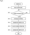
- Figure 4 shows the control in the event of a power interruption.
- the control circuit 15 executes initialization of itself (S1).
- the shutoff valves 12 and 13 are opened, and the changeover switch circuit 27 is set to OFF. Then, it waits until a power interruption occurs in the alternating-current power source 18 (S2).
- shutoff valves 12 and 13 are in an open state when the shutoff valve devices 3, 31 are shipped from the factory, but if they are closed due to a power interruption during the previous operation or the like, the control circuit 15 operates the valve drive circuit 24 using power from the power source circuit 23 to control the shutoff valves 12 and 13 to be fully open in the initialization in step S1 described above.
- step S2 When a power interruption has occurred in step S2 (Yes), the system transitions to a stopped state (S3), and the control circuit 15 sets the changeover switch circuit 27 to ON (S4). Then, power is supplied from the backup power source 16, and the valve closing operation of the shutoff valves 12 and 13 is performed (S5). Then, when the valve closing operation has been completed, the changeover switch circuit 27 is set to OFF (S6) and the process ends.
- the valve drive circuit 24 notifies the control circuit 15 that the valve closing operation has ended, and a method in which the valve closing time it takes for both the shutoff valves 12 and 13 to transition from full open to full closure is measured in advance and the control circuit 15 makes an independent determination based on the valve closing time having elapsed since the start of the valve closing operation. Furthermore, the completion of the valve closing operation may be determined based on the earlier one of the time when the notification of the end of the valve closing operation from the valve drive circuit 24 has reached the control circuit 15 and the elapsed time from the start of the valve closing operation by the valve drive circuit 24 to the elapse of the valve closing time.
- step S3 the system is stopped by notifying the control circuit 5 of the indoor unit 1 and the control circuit of the outdoor unit 2 that a power interruption has occurred. If the indoor unit 1 and the outdoor unit 2 are connected to the same alternating-current power source 18, each unit experiences a power interruption in the same way, and therefore the system has already been stopped as the whole air conditioning device in the event of a power interruption, but when the indoor unit 1 or the outdoor unit 2 receives power from an alternating-current power source other than that of the shutoff valve device 3, the unit is still able to operate, and therefore the control circuit 15 notifies the control circuit 5 of the indoor unit 1 or the control circuit of the outdoor unit 2 that a power interruption has occurred, thereby causing it to stop operating as an air conditioning device.
- step S4 is executed by the control circuit 15B and the other processes are executed by the control circuit 15A while communication is performed between the control circuits 15A and 15B as appropriate.
- the air conditioning device includes: the shutoff valves 12, 13 that are disposed in the pipes 10, 11 connecting the indoor unit 1 and the outdoor unit 2 to circulate the refrigerant and that are opened and closed by power from the alternating-current power source 18; the shutoff valve drive circuit 24; the backup power source 16 capable of alternatively supplying power to the shutoff valve drive circuit 24 when a power interruption has occurred in the alternating-current power source 18; the changeover switch circuit 27 that is disposed in the power supply path from the backup power source 16 to the shutoff valve drive circuit 24; the control circuit 15 that controls the shutoff valves 12, 13 and the changeover switch circuit 27; and the power interruption detection circuit 26 that detects a power interruption in the alternating-current power source 18.
- the control circuit 15 closes the changeover switch circuit 27, which is normally open, to close the shutoff valves 12 and 13. Then, the changeover switch circuit 27 is opened.
- the changeover switch circuit 27 In an air conditioning device including a backup power source, if the changeover switch circuit 27 is not present, the backup power source and the power source circuit are directly connected. Therefore, although the amount is small, the power of the backup power source is always consumed by the power source circuit and peripheral circuits such as a voltage detection circuit (not shown). The number of times the battery of the backup power source is charged and discharged is linked to its deterioration. Therefore, in the shutoff valve device 3 of this embodiment, after a power interruption occurs and the shutoff valves 12, 13 are closed, the changeover switch circuit 27 is set to OFF to electrically disconnect the backup power source 16 and the power source circuit 28.
- control circuit 15 composed of the MCU and the like to which power is supplied from the power source circuit 28 also stops, and signals are no longer generated between the control circuit 15 and the backup power source 16.
- unnecessary consumption of the battery of the backup power source 16 can be reduced as much as possible, and therefore deterioration of the backup power source 16 can be reduced.
- the changeover switch circuit 27 is set to OFF by initialization of the control circuit 15 in step S1 shown in Figure 4 .
- the second embodiment is obtained by adding a deterioration diagnosis process for the backup power source 16 to the control in the first embodiment.
- the backup power source 16 is made up of a plurality of nickel-metal hydride battery unit cells connected in series, and the voltage of a unit cell in a fully charged state is about 1.3 V.
- Figure 5 shows an example of changes in the cell voltage and battery capacity of one unit cell in a case where one cycle is composed of charging of one unit time, one hour of rest, discharging of one unit time, and one hour of rest at a predetermined temperature and is repeated up to 500 cycles. It is assumed that the battery capacity after the repetitions up to 500 cycles is 80% and the battery capacity required to close the shutoff valves 12, 13 is also 80%. The cell voltage at that time is just over 1.0 V. Therefore, a voltage of 1.0 V is set as the threshold for determining whether the backup power source 16 has deteriorated.
- the control circuit 15 executes steps S1 to S4, and immediately after the changeover switch is set to ON in step S4 after the occurrence of a power interruption, it determines whether the backup power source 16 is in a fully charged state (S11).
- step S12 If it is not in a fully charged state (NO), the situation is not suitable for deterioration diagnosis, the deterioration diagnosis is therefore terminated at that point (S12), the valve closing operation of the shutoff valves 12, 13 is performed (S132) as in step S5, and then the changeover switch is set to OFF (S6) to end the process (Send).
- step Send since the supply to the power source itself for the control circuit 15 has been stopped by setting the changeover switch to OFF, step Send does not exist as control, but it is represented as a step for convenience of explanation.
- the valve closing operation is performed (S5), and the voltage of the backup power source 16 after the valve closing operation is measured (S13). If the measured voltage is 1.0 V or higher (S14; YES), it is determined that the backup power source 16 has not deteriorated, and then the changeover switch circuit 27 is set to OFF (S6) to end the process (Send). If the measured voltage is less than 1.0 V (NO), it is determined that the backup power source 16 has deteriorated (S15). Then, the control circuit 15 stores the deterioration determination status in a memory (S16), and then sets the changeover switch circuit 27 to OFF (S6) to end the process (Send).
- step S1 when the power supply from the alternating-current power source 18 is resumed, the control circuit 15 performs initialization (S17) as in step S1, and then, if the deterioration determination status stored in the memory is deterioration information, outputs an alarm to notify the deterioration of the backup power source 16. On the other hand, if deterioration information is not stored in the memory, the state is normal, and therefore the process proceeds to step S2 without any particular notification.
- the control circuit 15 determines whether or not the backup power source 16 has deteriorated in parallel with the valve closing operation. This makes it possible to efficiently perform the deterioration determination.
- the deterioration diagnosis process for the backup power source 16 is forcibly performed by utilizing the discharging circuit 29. This deterioration diagnosis process is carried out while the power source 18 is energized. As shown in Figure 7 , it is determined whether the certain period of time has elapsed since the last deterioration diagnosis (S21). Here, the certain period of time is set to, for example, about one month. If the certain period of time has not elapsed (NO), the process ends without carrying out the deterioration diagnosis (S22).
- steps S4 and S11 are executed, then the switch circuit of the discharging circuit 29 is set to ON (S23), and the backup power source 16 is forcibly discharged at the consumed current equal to that when the shutoff valves 12 and 13 are closed (S24). Thereafter, when the switch circuit of the discharging circuit 29 has been set to OFF (S25), steps S13 to S15 are executed as in the second embodiment.
- step S18 a notification that the battery of the backup power source 16 has deteriorated is issued, and its state is stored in memory.
- the changeover switch is set to OFF to end the deterioration diagnosis process. The user recognizes the notification of deterioration of the backup power source 16 in step S18, and requests a maintenance and inspection worker to replace the battery of the backup power source 16, and the maintenance and inspection worker replaces the battery of the backup power source 16 with a new one.
- the control circuit 15 when a period of time during which no power interruption in the alternating-current power source 18 is detected has reached a predetermined length, the control circuit 15 performs deterioration diagnosis by causing the discharging circuit 29 to discharge the backup power source 16, and therefore it is possible to confirm the soundness of the backup power source 16 at least every time the predetermined period of time elapses, and it is possible to avoid a situation in which the valve closing operation of the shutoff valves 12, 13 cannot be performed due to a power shortage of the backup power source 16 in the event of a power interruption.
- shutoff valves are not limited to electronically controlled valves driven by a motor, but may be any valves that can be opened and closed using electricity.
- the changeover switch circuit is not limited to a MOSFET, but may be a mechanical relay that drives a contact.
- the cell voltage threshold for deterioration diagnosis is not limited to 1.0 V but may be changed as appropriate.
- the predetermined period of time that is an interval of deterioration diagnosis is not limited to one month, it is desirably a long period of time of one month or more because frequently performing the forced discharge that is executed during deterioration diagnosis can itself cause deterioration of the battery of the backup power source 16.
- the backup power source is not limited to a nickel-metal hydride battery, but may be of another type, for example, a lithium-ion battery.
- 1 indicates the indoor unit
- 2 indicates the outdoor unit
- 3 and 31 indicate the shutoff valve devices
- 4 indicates the refrigerant detection alarm (the refrigerant leakage detection unit)
- 10 and 11 indicate the refrigerant pipes
- 15, 15A, and 15B indicate the control circuits
- 16 indicates the backup power source
- 24 indicates the valve drive circuit
- 27 indicates the changeover switch circuit (the open and close switch)
- 29 indicates the discharging circuit.
Landscapes
- Engineering & Computer Science (AREA)
- Physics & Mathematics (AREA)
- Mechanical Engineering (AREA)
- Thermal Sciences (AREA)
- General Engineering & Computer Science (AREA)
- Stand-By Power Supply Arrangements (AREA)
Applications Claiming Priority (1)
| Application Number | Priority Date | Filing Date | Title |
|---|---|---|---|
| PCT/JP2022/029493 WO2024028946A1 (ja) | 2022-08-01 | 2022-08-01 | 冷凍サイクル装置 |
Publications (1)
| Publication Number | Publication Date |
|---|---|
| EP4567338A1 true EP4567338A1 (de) | 2025-06-11 |
Family
ID=89848690
Family Applications (1)
| Application Number | Title | Priority Date | Filing Date |
|---|---|---|---|
| EP22953936.6A Pending EP4567338A1 (de) | 2022-08-01 | 2022-08-01 | Kältekreislaufvorrichtung |
Country Status (4)
| Country | Link |
|---|---|
| US (1) | US20260022877A1 (de) |
| EP (1) | EP4567338A1 (de) |
| JP (1) | JP7769127B2 (de) |
| WO (1) | WO2024028946A1 (de) |
Families Citing this family (3)
| Publication number | Priority date | Publication date | Assignee | Title |
|---|---|---|---|---|
| JP7758087B2 (ja) * | 2024-03-29 | 2025-10-22 | 株式会社富士通ゼネラル | 空気調和機 |
| JP7775543B2 (ja) * | 2024-03-29 | 2025-11-26 | 株式会社富士通ゼネラル | 空気調和機 |
| WO2025246977A1 (zh) * | 2024-05-28 | 2025-12-04 | 广东美的暖通设备有限公司 | 暖通系统及其电控系统 |
Family Cites Families (7)
| Publication number | Priority date | Publication date | Assignee | Title |
|---|---|---|---|---|
| JPH1172262A (ja) * | 1997-08-29 | 1999-03-16 | Daikin Ind Ltd | 空気調和装置 |
| JP2013210110A (ja) | 2012-03-30 | 2013-10-10 | Hitachi Appliances Inc | 空気調和機 |
| JPWO2018078729A1 (ja) | 2016-10-25 | 2019-09-05 | 三菱電機株式会社 | 冷凍サイクル装置 |
| WO2020110425A1 (ja) * | 2018-11-26 | 2020-06-04 | 日立ジョンソンコントロールズ空調株式会社 | 空気調和システム及び冷媒漏洩防止システム |
| JP7407374B2 (ja) | 2019-02-19 | 2024-01-04 | パナソニックIpマネジメント株式会社 | 空気調和装置 |
| JP7175936B2 (ja) * | 2020-05-13 | 2022-11-21 | ダイキン工業株式会社 | ヒートポンプ装置 |
| JP7415017B2 (ja) * | 2020-08-19 | 2024-01-16 | 三菱電機株式会社 | 空気調和装置 |
-
2022
- 2022-08-01 US US19/100,111 patent/US20260022877A1/en active Pending
- 2022-08-01 EP EP22953936.6A patent/EP4567338A1/de active Pending
- 2022-08-01 WO PCT/JP2022/029493 patent/WO2024028946A1/ja not_active Ceased
- 2022-08-01 JP JP2024538540A patent/JP7769127B2/ja active Active
Also Published As
| Publication number | Publication date |
|---|---|
| WO2024028946A1 (ja) | 2024-02-08 |
| JP7769127B2 (ja) | 2025-11-12 |
| US20260022877A1 (en) | 2026-01-22 |
| JPWO2024028946A1 (de) | 2024-02-08 |
Similar Documents
| Publication | Publication Date | Title |
|---|---|---|
| EP4567338A1 (de) | Kältekreislaufvorrichtung | |
| JP7466061B2 (ja) | 冷凍サイクルの遮断弁制御装置及び空気調和装置 | |
| US12467670B2 (en) | Heat pump device | |
| EP2309213B1 (de) | Klimaanlagensystem und Betriebssteuerungsverfahren dafür | |
| JP7407374B2 (ja) | 空気調和装置 | |
| JP2022176373A (ja) | ヒートポンプ装置及び弁キット | |
| JPWO2020110425A1 (ja) | 空気調和システム及び冷媒漏洩防止システム | |
| JP7012692B2 (ja) | ヒートポンプ装置及び弁キット | |
| EP4008975B1 (de) | Klimatisierungssystem | |
| US9360244B2 (en) | Engine driven heat pump | |
| EP2001096A9 (de) | Steuerung | |
| US10047993B2 (en) | Engine driven heat pump | |
| EP4557572A1 (de) | Steuerungsvorrichtung, absperrventilschaltung mit steuerungsvorrichtung, klimaanlage mit steuerungsvorrichtung und steuerungsverfahren | |
| CN119532927B (zh) | 空调的运行监测方法及介质 | |
| EP4379274A1 (de) | Klimaanlage | |
| CN221526830U (zh) | 控制装置和空调器 | |
| CN223246294U (zh) | 备电装置的保护系统及风力发电机组 | |
| CN221403406U (zh) | 空调器的控制装置和空调器 | |
| US20250362046A1 (en) | Battery pack, air conditioning system, and method for the same | |
| EP4692687A1 (de) | Klimaanlage | |
| JP2024008576A (ja) | 照明装置および照明制御システム | |
| KR20110040634A (ko) | 실내기, 이를 포함한 공기 조화기, 및 공기 조화기의 운전 제어 방법 | |
| CN120043232A (zh) | 空调器的控制装置及其控制方法、设备和存储介质 | |
| KR100776599B1 (ko) | 시스템 에어컨의 운전장치 및 그 제어방법 | |
| CN120292697A (zh) | 控制装置及其健康状态检测方法、设备和存储介质 |
Legal Events
| Date | Code | Title | Description |
|---|---|---|---|
| STAA | Information on the status of an ep patent application or granted ep patent |
Free format text: STATUS: THE INTERNATIONAL PUBLICATION HAS BEEN MADE |
|
| PUAI | Public reference made under article 153(3) epc to a published international application that has entered the european phase |
Free format text: ORIGINAL CODE: 0009012 |
|
| STAA | Information on the status of an ep patent application or granted ep patent |
Free format text: STATUS: REQUEST FOR EXAMINATION WAS MADE |
|
| 17P | Request for examination filed |
Effective date: 20250116 |
|
| AK | Designated contracting states |
Kind code of ref document: A1 Designated state(s): AL AT BE BG CH CY CZ DE DK EE ES FI FR GB GR HR HU IE IS IT LI LT LU LV MC MK MT NL NO PL PT RO RS SE SI SK SM TR |
|
| DAV | Request for validation of the european patent (deleted) | ||
| DAX | Request for extension of the european patent (deleted) |