EP4567201A1 - Videoaufzeichnungssystem - Google Patents
Videoaufzeichnungssystem Download PDFInfo
- Publication number
- EP4567201A1 EP4567201A1 EP23871688.0A EP23871688A EP4567201A1 EP 4567201 A1 EP4567201 A1 EP 4567201A1 EP 23871688 A EP23871688 A EP 23871688A EP 4567201 A1 EP4567201 A1 EP 4567201A1
- Authority
- EP
- European Patent Office
- Prior art keywords
- construction machinery
- video recording
- video
- sign
- vehicle body
- Prior art date
- Legal status (The legal status is an assumption and is not a legal conclusion. Google has not performed a legal analysis and makes no representation as to the accuracy of the status listed.)
- Pending
Links
Images


Classifications
-
- E—FIXED CONSTRUCTIONS
- E02—HYDRAULIC ENGINEERING; FOUNDATIONS; SOIL SHIFTING
- E02F—DREDGING; SOIL-SHIFTING
- E02F9/00—Component parts of dredgers or soil-shifting machines, not restricted to one of the kinds covered by groups E02F3/00 - E02F7/00
- E02F9/24—Safety devices, e.g. for preventing overload
-
- E—FIXED CONSTRUCTIONS
- E02—HYDRAULIC ENGINEERING; FOUNDATIONS; SOIL SHIFTING
- E02F—DREDGING; SOIL-SHIFTING
- E02F3/00—Dredgers; Soil-shifting machines
- E02F3/04—Dredgers; Soil-shifting machines mechanically-driven
- E02F3/28—Dredgers; Soil-shifting machines mechanically-driven with digging tools mounted on a dipper- or bucket-arm, i.e. there is either one arm or a pair of arms, e.g. dippers, buckets
- E02F3/36—Component parts
- E02F3/42—Drives for dippers, buckets, dipper-arms or bucket-arms
- E02F3/43—Control of dipper or bucket position; Control of sequence of drive operations
- E02F3/435—Control of dipper or bucket position; Control of sequence of drive operations for dipper-arms, backhoes or the like
-
- E—FIXED CONSTRUCTIONS
- E02—HYDRAULIC ENGINEERING; FOUNDATIONS; SOIL SHIFTING
- E02F—DREDGING; SOIL-SHIFTING
- E02F9/00—Component parts of dredgers or soil-shifting machines, not restricted to one of the kinds covered by groups E02F3/00 - E02F7/00
- E02F9/20—Drives; Control devices
-
- E—FIXED CONSTRUCTIONS
- E02—HYDRAULIC ENGINEERING; FOUNDATIONS; SOIL SHIFTING
- E02F—DREDGING; SOIL-SHIFTING
- E02F9/00—Component parts of dredgers or soil-shifting machines, not restricted to one of the kinds covered by groups E02F3/00 - E02F7/00
- E02F9/26—Indicating devices
-
- E—FIXED CONSTRUCTIONS
- E02—HYDRAULIC ENGINEERING; FOUNDATIONS; SOIL SHIFTING
- E02F—DREDGING; SOIL-SHIFTING
- E02F9/00—Component parts of dredgers or soil-shifting machines, not restricted to one of the kinds covered by groups E02F3/00 - E02F7/00
- E02F9/26—Indicating devices
- E02F9/261—Surveying the work-site to be treated
-
- H—ELECTRICITY
- H04—ELECTRIC COMMUNICATION TECHNIQUE
- H04N—PICTORIAL COMMUNICATION, e.g. TELEVISION
- H04N21/00—Selective content distribution, e.g. interactive television or video on demand [VOD]
- H04N21/20—Servers specifically adapted for the distribution of content, e.g. VOD servers; Operations thereof
- H04N21/25—Management operations performed by the server for facilitating the content distribution or administrating data related to end-users or client devices, e.g. end-user or client device authentication, learning user preferences for recommending movies
- H04N21/266—Channel or content management, e.g. generation and management of keys and entitlement messages in a conditional access system, merging a VOD unicast channel into a multicast channel
- H04N21/2665—Gathering content from different sources, e.g. Internet and satellite
-
- H—ELECTRICITY
- H04—ELECTRIC COMMUNICATION TECHNIQUE
- H04N—PICTORIAL COMMUNICATION, e.g. TELEVISION
- H04N21/00—Selective content distribution, e.g. interactive television or video on demand [VOD]
- H04N21/20—Servers specifically adapted for the distribution of content, e.g. VOD servers; Operations thereof
- H04N21/27—Server based end-user applications
- H04N21/274—Storing end-user multimedia data in response to end-user request, e.g. network recorder
-
- H—ELECTRICITY
- H04—ELECTRIC COMMUNICATION TECHNIQUE
- H04N—PICTORIAL COMMUNICATION, e.g. TELEVISION
- H04N21/00—Selective content distribution, e.g. interactive television or video on demand [VOD]
- H04N21/40—Client devices specifically adapted for the reception of or interaction with content, e.g. set-top-box [STB]; Operations thereof
- H04N21/43—Processing of content or additional data, e.g. demultiplexing additional data from a digital video stream; Elementary client operations, e.g. monitoring of home network or synchronising decoder's clock; Client middleware
- H04N21/431—Generation of visual interfaces for content selection or interaction; Content or additional data rendering
- H04N21/4312—Generation of visual interfaces for content selection or interaction; Content or additional data rendering involving specific graphical features, e.g. screen layout, special fonts or colors, blinking icons, highlights or animations
- H04N21/4316—Generation of visual interfaces for content selection or interaction; Content or additional data rendering involving specific graphical features, e.g. screen layout, special fonts or colors, blinking icons, highlights or animations for displaying supplemental content in a region of the screen, e.g. an advertisement in a separate window
-
- H—ELECTRICITY
- H04—ELECTRIC COMMUNICATION TECHNIQUE
- H04N—PICTORIAL COMMUNICATION, e.g. TELEVISION
- H04N21/00—Selective content distribution, e.g. interactive television or video on demand [VOD]
- H04N21/40—Client devices specifically adapted for the reception of or interaction with content, e.g. set-top-box [STB]; Operations thereof
- H04N21/45—Management operations performed by the client for facilitating the reception of or the interaction with the content or administrating data related to the end-user or to the client device itself, e.g. learning user preferences for recommending movies, resolving scheduling conflicts
- H04N21/462—Content or additional data management, e.g. creating a master electronic program guide from data received from the Internet and a Head-end, controlling the complexity of a video stream by scaling the resolution or bit-rate based on the client capabilities
- H04N21/4622—Retrieving content or additional data from different sources, e.g. from a broadcast channel and the Internet
-
- H—ELECTRICITY
- H04—ELECTRIC COMMUNICATION TECHNIQUE
- H04N—PICTORIAL COMMUNICATION, e.g. TELEVISION
- H04N21/00—Selective content distribution, e.g. interactive television or video on demand [VOD]
- H04N21/40—Client devices specifically adapted for the reception of or interaction with content, e.g. set-top-box [STB]; Operations thereof
- H04N21/47—End-user applications
- H04N21/472—End-user interface for requesting content, additional data or services; End-user interface for interacting with content, e.g. for content reservation or setting reminders, for requesting event notification, for manipulating displayed content
- H04N21/47217—End-user interface for requesting content, additional data or services; End-user interface for interacting with content, e.g. for content reservation or setting reminders, for requesting event notification, for manipulating displayed content for controlling playback functions for recorded or on-demand content, e.g. using progress bars, mode or play-point indicators or bookmarks
-
- H—ELECTRICITY
- H04—ELECTRIC COMMUNICATION TECHNIQUE
- H04N—PICTORIAL COMMUNICATION, e.g. TELEVISION
- H04N5/00—Details of television systems
- H04N5/76—Television signal recording
- H04N5/765—Interface circuits between an apparatus for recording and another apparatus
- H04N5/77—Interface circuits between an apparatus for recording and another apparatus between a recording apparatus and a television camera
-
- H—ELECTRICITY
- H04—ELECTRIC COMMUNICATION TECHNIQUE
- H04N—PICTORIAL COMMUNICATION, e.g. TELEVISION
- H04N7/00—Television systems
- H04N7/18—Closed-circuit television [CCTV] systems, i.e. systems in which the video signal is not broadcast
-
- H—ELECTRICITY
- H04—ELECTRIC COMMUNICATION TECHNIQUE
- H04N—PICTORIAL COMMUNICATION, e.g. TELEVISION
- H04N7/00—Television systems
- H04N7/18—Closed-circuit television [CCTV] systems, i.e. systems in which the video signal is not broadcast
- H04N7/183—Closed-circuit television [CCTV] systems, i.e. systems in which the video signal is not broadcast for receiving images from a single remote source
-
- B—PERFORMING OPERATIONS; TRANSPORTING
- B60—VEHICLES IN GENERAL
- B60Y—INDEXING SCHEME RELATING TO ASPECTS CROSS-CUTTING VEHICLE TECHNOLOGY
- B60Y2200/00—Type of vehicle
- B60Y2200/40—Special vehicles
- B60Y2200/41—Construction vehicles, e.g. graders, excavators
- B60Y2200/412—Excavators
Definitions
- Patent Document 1 Japanese Patent No. 4394780
- Patent Document 1 discloses saving recorded video using the impact detected by the vehicle's acceleration sensor as a trigger.
- construction machinery is constantly subjected to impacts and large vibrations due to operations, so it is not uncommon for impacts equivalent to accidents to occur even during normal operation. Therefore, it is not appropriate to use the same trigger for starting recording in construction machinery as in automobiles.
- the present invention has been made in consideration of the above points and proposes a video recording system that facilitates the extraction of surrounding images during the occurrence of events such as near-miss accident, thereby simplifying the verification work for such incidents.
- a video recording system for recording the surroundings of construction machinery includes a video recording system including a camera that captures the surroundings of the construction machinery, one or more types of sensors that detect the state of the construction machinery, a controller that detects a sign of the construction machinery tipping over or a part of the construction machinery coming into contact with surrounding objects, based on the output of the sensor or the surrounding images of the construction machinery captured by the camera, a video recording device that records the surrounding images of the construction machinery captured by the camera, triggered by the controller detecting the sign.
- the video recording system of the present invention can limit the recording timing of the surrounding images of construction machinery when an operation is performed that may cause the construction machinery to tip over or a part of the construction machinery to contact surrounding objects, i.e., when a near-miss accident occurs.
- a video recording system can be realized that facilitates the extraction of surrounding images during the occurrence of events such as near-miss accident and simplifies the verification work for such incidents.
- FIG. 1 indicates a construction machine (hydraulic excavator) equipped with the operation information recording system according to the present embodiment as a whole.
- This construction machine 1 is configured with a self-propelled lower travel body 2, an upper swing body 3 mounted rotatably on the lower travel body 2, and a front device 4 connected to the front of the upper swing body 3.
- the upper swing body 3 is equipped with an engine 5 as a power source and a main pump 6 driven by the engine 5.
- the hydraulic oil delivered by the main pump 6 allows the lower travel body 2, the upper swing body 3, and the front device 4 to operate independently.
- the lower travel body 2 is equipped with a pair of travel hydraulic motors 7 driven by the hydraulic oil delivered from the main pump 6, mounted on the left and right rear sides.
- the crawlers 8 provided on both sides in the left-right direction of the lower travel body 2 can be independently driven to rotate. This allows the entire construction machine 1 with the lower travel body 2 to travel in the front-rear direction or to swing in the left-right direction.
- the front device 4 is a working device that directly performs operations such as excavation or leveling of the ground, or lifting excavated soil and other loads.
- the front device 4 includes a boom 11 connected to the upper swing body 3 so that one end side can rotate in the front-rear direction of the upper swing body 3 via the rotating shaft 10,and an arm 13 with one end rotatably connected to the other end of the boom 11 via a rotating shaft 12, and a bucket 15 rotatably connected to the other end of the arm 13 via a rotating shaft 14.
- the device 4 is configured with a boom cylinder 16, an arm cylinder 17, and a bucket cylinder 18, which can be extended and retracted by the hydraulic oil delivered from the main pump 6.
- the arm cylinder 17 is connected to the boom 11 at one end and to the arm 13 at the other end via a rotating shaft 20. This allows the arm cylinder 17 to be driven to extend and retract, and the arm 13 to be rotated around the rotating shaft 12.
- the bucket cylinder 18 is connected to the arm 13 at one end and to the bucket 15 at the other end via a link. This allows the bucket cylinder 18 to be driven to extend and retract, and the bucket 15 to be rotated around the rotating shaft 14.
- FIG. 2 shows the configuration of the operation information recording system 30 of the present embodiment mounted on the construction machine 1.
- This operation information recording system 30 is a system for recording video data of the surrounding images and vehicle body data of the construction machine 1 during its operation when a near-miss accident is detected.
- the operation information recording system 30 detects a sign that the posture of the construction machine 1 changes and tipping over, or the sign that the front device 4 contacts surrounding objects, as an example.
- the operation information recording system 30 is mounted on the construction machinery 1 and is configured with various sensors such as multiple surrounding monitoring cameras 31, an inclination sensor 32, a swing angle sensor 33, a boom angle sensor 34, an arm angle sensor 35, and a load sensor 36, as well as a monitor controller 37, a monitor 38, a vehicle body controller 39, a video recording device 40, and a communication terminal 41, each arranged in the operator's seat 3A of the upper swing body 3 ( Fig. 1 ). Additionally, the monitor controller 37, monitor 38, vehicle body controller 39, and video recording device 40 are communicatively connected via an in-vehicle network 42 such as a CAN network.
- an in-vehicle network 42 such as a CAN network.
- the surrounding monitoring cameras 31 are cameras for capturing the surroundings of the construction machinery 1, and are arranged in multiple locations on the upper part of the upper swing body 3 to capture the left and right sides, front, and rear. Each surrounding monitoring camera 31 outputs the video data of the surrounding images of the construction machinery 1 obtained by capturing to the monitor controller 37.
- the inclination sensor 32 and the swing angle sensor 33 are each arranged on the upper swing body 3.
- the inclination sensor 32 detects the tilt angles in the front-rear and left-right directions of the upper swing body 3 (i.e., the pitch and roll angles of the upper swing body 3 with the front direction as the roll axis direction) and outputs these detected tilt angles to the vehicle body controller 39.
- the swing angle sensor 33 detects the swing angle of the upper swing body 3 relative to the lower travel body 2 and outputs the detected swing angle to the vehicle body controller 39.
- the boom angle sensor 34, arm angle sensor 35, and load sensor 36 are each arranged on the front device 4.
- the boom angle sensor 34 detects the posture of the boom 11 as the tilt angle from the reference state (hereinafter referred to as the boom tilt angle) and outputs the detected boom tilt angle to the vehicle body controller 39.
- the arm angle sensor 35 detects the posture of the arm 13 as the tilt angle from the reference state relative to the boom 11 (hereinafter referred to as the arm tilt angle) and outputs the detected arm tilt angle to the vehicle body controller 39. Furthermore, the load sensor 36 detects the load of the suspended load lifted by the front device 4 and outputs the detected load to the vehicle body controller 39.
- the monitor controller 37 generates composite images such as split images where the surrounding images captured by each surrounding monitoring camera 31 are displayed in segments, or surround view images where the boundaries of the surrounding images captured by adjacent surrounding monitoring cameras 31 are blended, based on the video data provided by each surrounding monitoring camera 31.
- the monitor controller 37 then transmits the video data of the generated composite images to the monitor 38 and the video recording device 40 via the communication line 43.
- the monitor 38 is composed of a display device such as an LCD panel or an organic EL (Electro-Luminescence) panel.
- the monitor 38 displays the composite images based on the video data provided by the monitor controller 37 via the communication line 43.
- the vehicle body controller 39 transmits the sensor data provided by the inclination sensor 32, swing angle sensor 33, boom angle sensor 34, arm angle sensor 35, and load sensor 36 to the video recording device 40 via the in-vehicle network 42. Additionally, the vehicle body controller 39 monitors these sensor data and, when the lock of the gate lock device 45 provided in the operator's seat 3A is released, if it detects a sign that the construction machinery 1 is tipping over or the front device 4 is contacting surrounding objects, it sends a recording trigger signal to the video recording device 40 via the in-vehicle network 42 to initiate recording. Details of the 'sign of the construction machinery 1's posture changing leading to tipping over, or the front device 4 contacting surrounding objects' will be described later.
- the vehicle body controller 39 is also provided with sensor data representing the pressure of the hydraulic oil supplied to the travel hydraulic motor 7, swing hydraulic motor 9, boom cylinder 16, arm cylinder 17, and bucket cylinder 18, detected by hydraulic sensors attached to these components as described in Fig. 1 .
- the vehicle body controller 39 also transmits the sensor data provided by these hydraulic sensors to the video recording device 40 via the in-vehicle network 42.
- the video recording device 40 is configured with storage devices such as semiconductor memory like flash memory, or hard disk drives or SSDs (Solid State Drives).
- the video recording device 40 is provided with the video data of the composite images from the monitor controller 37 and the sensor data from various sensors from the vehicle body controller 39 as described above.
- the video recording device 40 is sequentially provided with engine speed data representing the rotation speed of the engine 5 ( Fig. 1 ) from an ECU (Electronic Control Unit) not shown.
- the video recording device 40 temporarily and sequentially stores the video data of the composite images provided by the monitor controller 37 for a certain recent period, and also temporarily and sequentially stores the sensor data from various sensors provided by the vehicle body controller 39 and the engine speed data provided by the ECU as vehicle body data, linking them with the composite images generated at the same time for the same recent period.
- the video recording device 40 also stores and saves the current position of the construction machinery 1 at the time notified by the communication terminal 41 in the sign detection data file, as described later. Then, the video recording device 40 uploads (transmits) the saved sign detection data file to the external server device 47 via wireless communication through the communication terminal 41 and the antenna 46 provided on the upper swing body 3 at an appropriate timing.
- the communication terminal 41 is a communication device capable of bidirectional communication with the external server device 47 via a wireless communication line such as a mobile phone line. This allows the operation information recording system 30 not only to upload the aforementioned files to the external server device 47 but also enables the external server device 47 to access the operation information recording system 30.
- This communication terminal is equipped with a GPS (Global Positioning System) receiver.
- the communication terminal sequentially detects its current position based on the GPS signals received by this GPS receiver and notifies the detected current position to the video recording device 40.
- this current position is stored in the sign detection data file as described above and uploaded to the external server device 47.
- the external server device 47 is composed of a general-purpose server device equipped with a CPU (Central Processing Unit), a main storage device such as semiconductor memory, an auxiliary storage device such as a hard disk drive, input devices such as a mouse and keyboard, and display devices such as an LCD display or an organic EL display, and is provided separately from the construction machinery 1.
- a CPU Central Processing Unit
- main storage device such as semiconductor memory
- auxiliary storage device such as a hard disk drive
- input devices such as a mouse and keyboard
- display devices such as an LCD display or an organic EL display
- the external server device 47 accumulates and manages the sign detection data files appropriately transmitted from one or more construction machinery 1 under its management.
- the external server device 47 also displays the composite images and other necessary information based on the accumulated sign detection data, according to the user's predetermined operations, when the vehicle body controller 39 of each construction machinery 1 detects sign of posture change leading to tipping over or the front device 4 contacting surrounding objects.
- a single video recording system is constructed by the external server device 47 and the operation information recording system 30 of one or more construction machinery 1 under the management of the external server device 47.
- the user of this video recording system can use the sign detection data accumulated in the external server device 47 to more thoroughly verify the operator's actions that led to the detection of sign of posture change leading to tipping over or the front device 4 contacting surrounding objects, using statistical methods and the like. Additionally, the user of the video recording system can use the verification results for future training of the operator of the construction machinery 1.
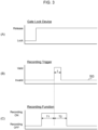
- FIG 3 shows the state of the gate lock device 45 and the recording timing of the sign detection data.
- the vehicle body controller 39 as shown in FIG. 3(A) , sends a recording trigger signal SG, which is valid for a predetermined time t, to the video recording device 40 when the lock of the gate lock device 45 is released and operation is permitted, and when a sign of tipping of the construction machinery 1 or contact of the front device 4 with surrounding objects is detected, as shown in FIG. 3(B) .
- the video recording device 40 continues the recording for one session ((T1+T2) time of recording) until it is completed, even if the recording trigger signal SG switches from invalid to valid again, ignoring this and continuing the recording for that one session.
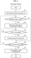
- FIG. 4 shows the flow of a series of processes (hereinafter referred to as recording processing) executed by the video recording device 40 in relation to the recording of surrounding images of the construction machinery 1 as described above.
- This recording process starts when the engine of the construction machinery 1 is started, the power of the vehicle body is turned on, and the power of the entire operation information recording system 30 ( FIG. 2 ) is turned on, and the preparation for recording is completed in the video recording device 40.
- the video recording device 40 first starts temporarily storing the video data provided by the monitor controller 37, etc., and the vehicle body data provided by the vehicle body controller 39 and ECU, etc. (S1), and then determines whether the recording trigger signal provided by the vehicle body controller 39 is valid (S2).
- the video recording device 40 starts saving the video data and vehicle body data temporarily stored from the time T1 before the point when the recording trigger signal became valid (S3).
- the video recording device 40 waits for time T2 to elapse from the point when the recording trigger signal became valid (S4). Then, when time T2 has elapsed from the point when the recording trigger signal became valid, the video recording device 40 completes the saving of the video data and vehicle body data. After that, the video recording device 40 files the (T1+T2) time of video data and vehicle body data saved up to that point, along with the position data of the current position of the vehicle body notified by the communication terminal 41 at that time, as sign detection data (S5).
- the video recording device 40 determines whether the power of the vehicle body has been turned off (S6). Then, if the video recording device 40 obtains a negative result in this determination, it returns to step S2 and repeats the processing from step S2 onward in the same manner as described above.
- the video recording device 40 obtains a positive result in step S6 and turns off its own power (S7). This ends the recording process.
- FIG. 5 shows the flow of a series of processes executed by the vehicle body controller 39 in parallel with the recording process described in FIG. 4 regarding the recording of the video data and vehicle body data.
- the vehicle body controller 39 generates a recording trigger signal according to the processing procedure shown in FIG. 5 and sends the generated recording trigger signal to the video recording device 40.
- recording trigger signal generation processing when the power of the vehicle body controller 39 is turned on, it starts the processing shown in FIG. 5 (hereinafter referred to as recording trigger signal generation processing). First, it determines whether predetermined conditions (hereinafter referred to as recording start conditions) that can start the recording trigger signal generation processing, such as the posture of the front device 4 and the rotation speed of the engine 5, are met (S10).
- the recording start conditions for example, conditions such as whether the posture of the front device 4 and the rotation speed of the engine 5 are within a predetermined range, or whether the current position of the construction machinery 1 is a predetermined location can be set. Then, if the vehicle body controller 39 obtains a negative result in this determination, it waits for such recording start conditions to be met.
- the vehicle body controller 39 first determines whether the lock of the gate lock device 45 ( FIG. 2 ) is released (S11). Then, if the vehicle body controller 39 obtains a negative result in this determination, it returns to step S10 and executes the processing from step S10 onward in the same manner as described above.
- step S13 the vehicle body controller 39 obtains a negative result in this determination. It returns to step S10 and repeats the processing from step S10 onward in the same manner as described above. On the other hand, if the vehicle body controller 39 obtains a positive result in the determination of step S12, it makes the recording trigger signal valid for time t (S13).
- the vehicle body controller 39 determines whether a sign of the construction machinery 1 tipping over or the front device 4 contacting surrounding objects is still being detected (S14). If the vehicle body controller 39 obtains a positive result in this determination, it waits for such sign to no longer be detected.
- the vehicle body controller 39 can set multiple such “signs.”
- the vehicle body controller 39 can set the first "sign" as "the posture (tilt) of the upper swing body 3 has at least one of the tilt angles in the front-rear direction and the left-right direction exceeding a predetermined threshold angle for these front-rear and left-right tilts.”
- the vehicle body controller 39 mounted on the construction machinery 1 of this embodiment originally has a function to issue a warning to the operator in the seat 3A by sound or images displayed on the monitor 38 when the inclination of the vehicle body exceeds a certain threshold angle, indicating a risk of the construction machinery 1 tipping over. Therefore, in this embodiment, when issuing such a warning to the operator, the vehicle body controller 39 also makes the recording trigger signal valid.
- the file of sign detection data recorded by the video recording device 40 includes not only the sensor data output from the inclination sensor 32 at that time but also the sensor data from various hydraulic sensors mentioned above, which serve as a basis for estimating the operator's actions on the construction machinery 1. This allows for later verification of what kind of operation by the operator caused the vehicle body of the construction machinery 1 to tilt, based on this sign detection data.
- the detection of the second "sign” can be set as "the size of the suspended load detected by the load sensor 36 of the front device 4 exceeds a predetermined threshold (hereinafter referred to as load threshold)."
- the vehicle body controller 39 mounted on the construction machinery 1 of this embodiment originally has a function to issue a warning to the operator in the seat 3A by sound or images displayed on the monitor 38 when the suspended load lifted by the front device 4 exceeds the load threshold and the tipping moment of the vehicle body becomes excessive due to the posture of the front device 4, indicating a risk of the construction machinery 1 tipping over.
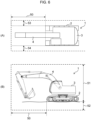
- the detection of the third "sign" can be set as "a part of the front device 4 has exceeded a predetermined operation restriction area.”
- the operator can set the operation restriction area of the front device 4 on the vehicle body controller 39 to prevent the vehicle body from contacting surrounding objects. Specifically, as shown in FIG 6 , the operator can set the forward restriction area 50 in the forward direction, the height restriction area 51 in the height direction, the depth restriction area 52 in the depth direction, the right restriction area 53 to the right, and the left restriction area 54 to the left, each based on the lower travel body 2.
- the vehicle body controller 39 constantly calculates the posture of the front device 4 based on the sensor data provided by the swing angle sensor 33, boom angle sensor 34, and arm angle sensor 35. Then, if the vehicle body controller 39 determines that a part of the front device 4 has exceeded any of the forward restriction area 50, height restriction area 51, depth restriction area 52, right restriction area 53, or left restriction area 54, it has the function to issue a warning to the operator in the driver's seat 3A through sound or images displayed on the monitor 38, and to stop the operation of the front device 4.
- the vehicle body controller 39 when issuing a warning to the operator, the vehicle body controller 39 simultaneously activates the recording trigger signal.
- the file of the sign detection data recorded by the video recording device 40 due to the detection of this "sign," includes information calculated by the vehicle body controller 39 on which direction the front device 4 exceeded the operation restriction area, as well as sensor data corresponding to the operation of swinging the upper swing body 3 and various operations by the operator on the front device 4. Based on this sign detection data, it is possible to later verify what kind of operation by the operator caused a part of the front device 4 to exceed the operation restriction area.
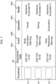
- FIG 7 shows the screen configuration of the sign detection case list screen 60, which can be displayed on the external server device 47 through a predetermined operation, based on the sign detection data uploaded from the construction machinery 1 to the external server device 47 ( FIG 2 ) as described above.
- the sign detection case list screen 60 displays a list of information on each case where a sign of tipping due to changes in the posture of construction machinery 1, or a sign of the front device 4 contacting surrounding objects, was detected, based on the sign detection data uploaded from each construction machinery 1 to the external server device 47.
- the occurrence date and time (“Occurrence Date”)
- Event the type of warning issued to the operator when the sign detection data was saved
- Event the content of the operation performed by the operator at that time recognized based on sensor data from each hydraulic sensor
- Model the model of the construction machinery 1 where the incident occurred
- FIG 7 shows a case where a "Body Inclination Warning” was issued on “2021/4/7 12:45” during the "Travel” operation of construction machinery 1 of the model “Hydraulic Excavator B,” indicating that the posture of the body of construction machinery 1 inclined beyond the permissible angle. Also, FIG 7 shows a case where a "Front Load Warning” was issued on "2021/4/3 18:30" during the “Swing” operation of construction machinery 1 of the model "Hydraulic Excavator A,” indicating that the load of the suspended load of the front device 4 exceeded the aforementioned load threshold.
- Figure 7 shows a case where an "Area Restriction Warning” was issued on “2021/4/1 15:00" during the "Excavation” operation of construction machinery 1 of the model "Hydraulic Excavator C,” indicating that a part of the front device 4 of the construction machinery 1 exceeded the restriction area (for example, the depth restriction area 52 in Figure 6 ).
- a pull-down menu (not shown) is displayed, from which the desired date or item can be specified. This allows the range of cases displayed on the sign detection case list screen 60 to be limited to cases corresponding to that date or item.
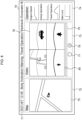
- the sign detection case list screen 60 can be replaced with, or overlaid on, the sign detection case list screen 60 that was displayed until then, by selecting a row corresponding to the desired case or double-clicking the thumbnail image 61, to display a screen like the one shown in FIG 8 based on the sign detection data of that case (hereinafter referred to as the case detail screen 70).
- This case detail screen 70 is configured with a case summary display area 71, a map display area 72, a video display area 73, and an operation information display area 74. Then, the case summary display area 71 displays a summary of the corresponding case, and the map display area 72 displays a bird's-eye map 75 of the location where the corresponding case occurred, based on the position data included in the sign detection data of the corresponding case.
- the video display area 73 displays the composite video 76 saved when the corresponding case occurred.
- Figure 8 shows an example where the composite video 76 is a split video.
- the composite video 76 displayed in the video display area 73 can be started or stopped by pressing (clicking) the play button 77 or stop button 78 displayed below the composite video 76.
- the composite video 76 can have its playback position moved to a position corresponding to the position of the slider 80 by dragging the slider 80 of the slider bar 79 displayed below the composite video 76 to the left or right.
- the operation information display area 74 displays the content of various operations by the operator before and after the occurrence date and time of the corresponding case in graph format.
- the engine speed (“Engine Speed”) before and after the occurrence date and time of the corresponding case is displayed in graph format as is.
- the hydraulic pressure of the hydraulic oil supplied to the swing hydraulic motor 9 ( FIG 1 ) (“Swing Operation”) is displayed in graph format as the content of the swing operation, and furthermore, the hydraulic pressure of the hydraulic oil supplied to the travel hydraulic motor 7 ( FIG 1 ) (“Travel Operation”) is displayed in graph format as the content of the travel operation.
- the state of the gate lock device 45 ( FIG 2 ) (“Gate Lock”) is displayed in the same format as in FIG 3(A) .
- the construction machinery is a hydraulic excavator
- the present invention is not limited to this and can be widely applied to various other construction machinery such as cranes and loaders.
- the sign detection case list screen 60 and the case detail screen 70 can be displayed only on the external server device 47 was described, but the present invention is not limited to this.
- the sign detection case list screen 60 and the case detail screen 70 may also be displayed on a client terminal connected to the external server device 47 via a network such as the Internet.
- the present invention can be widely applied to various construction machinery.
Landscapes
- Engineering & Computer Science (AREA)
- Multimedia (AREA)
- Signal Processing (AREA)
- Structural Engineering (AREA)
- General Engineering & Computer Science (AREA)
- Civil Engineering (AREA)
- Mining & Mineral Resources (AREA)
- Mechanical Engineering (AREA)
- Databases & Information Systems (AREA)
- Physics & Mathematics (AREA)
- Marketing (AREA)
- Business, Economics & Management (AREA)
- Human Computer Interaction (AREA)
- General Physics & Mathematics (AREA)
- Astronomy & Astrophysics (AREA)
- Component Parts Of Construction Machinery (AREA)
Applications Claiming Priority (2)
| Application Number | Priority Date | Filing Date | Title |
|---|---|---|---|
| JP2022159122 | 2022-09-30 | ||
| PCT/JP2023/031489 WO2024070448A1 (ja) | 2022-09-30 | 2023-08-30 | 映像記録システム |
Publications (1)
| Publication Number | Publication Date |
|---|---|
| EP4567201A1 true EP4567201A1 (de) | 2025-06-11 |
Family
ID=90477178
Family Applications (1)
| Application Number | Title | Priority Date | Filing Date |
|---|---|---|---|
| EP23871688.0A Pending EP4567201A1 (de) | 2022-09-30 | 2023-08-30 | Videoaufzeichnungssystem |
Country Status (5)
| Country | Link |
|---|---|
| EP (1) | EP4567201A1 (de) |
| JP (1) | JPWO2024070448A1 (de) |
| KR (1) | KR20250041015A (de) |
| CN (1) | CN119855963A (de) |
| WO (1) | WO2024070448A1 (de) |
Family Cites Families (5)
| Publication number | Priority date | Publication date | Assignee | Title |
|---|---|---|---|---|
| JP4394780B2 (ja) | 1999-10-08 | 2010-01-06 | クラリオン株式会社 | 移動体情報記録装置 |
| JP2004123362A (ja) * | 2002-10-07 | 2004-04-22 | Hitachi Constr Mach Co Ltd | フック付き建設機械 |
| US8473143B2 (en) * | 2008-12-02 | 2013-06-25 | Caterpillar Inc. | System and method for accident logging in an automated machine |
| KR102659153B1 (ko) * | 2018-03-20 | 2024-04-18 | 스미도모쥬기가이고교 가부시키가이샤 | 쇼벨, 정보처리장치 |
| JP7123877B2 (ja) * | 2019-08-13 | 2022-08-23 | 日立建機株式会社 | 記録システム |
-
2023
- 2023-08-30 WO PCT/JP2023/031489 patent/WO2024070448A1/ja not_active Ceased
- 2023-08-30 JP JP2024549916A patent/JPWO2024070448A1/ja active Pending
- 2023-08-30 CN CN202380064520.6A patent/CN119855963A/zh active Pending
- 2023-08-30 EP EP23871688.0A patent/EP4567201A1/de active Pending
- 2023-08-30 KR KR1020257005623A patent/KR20250041015A/ko active Pending
Also Published As
| Publication number | Publication date |
|---|---|
| WO2024070448A1 (ja) | 2024-04-04 |
| KR20250041015A (ko) | 2025-03-25 |
| CN119855963A (zh) | 2025-04-18 |
| JPWO2024070448A1 (de) | 2024-04-04 |
Similar Documents
| Publication | Publication Date | Title |
|---|---|---|
| JP7589410B2 (ja) | ショベル、情報処理装置 | |
| CN102947515B (zh) | 作业机械的周围监视装置 | |
| CN110344467B (zh) | 挖掘机测量和控制逻辑电路 | |
| CN1603528A (zh) | 施工机械的显示装置 | |
| WO2021025034A1 (ja) | 建設機械、建設機械の表示装置、及び、建設機械の管理装置 | |
| CN115280395A (zh) | 检测系统以及检测方法 | |
| CN1621628B (zh) | 工程建筑机械的显示装置 | |
| JP2019167733A (ja) | 建設機械 | |
| EP4567201A1 (de) | Videoaufzeichnungssystem | |
| CN115917092A (zh) | 作业机械的障碍物报知系统及作业机械的障碍物报知方法 | |
| US12000115B2 (en) | Hydraulic excavator | |
| US11987960B2 (en) | Work machine, information management system, information terminal, and program | |
| JP2000064359A (ja) | 自動運転建設機械 | |
| JP7580184B2 (ja) | 作業機械、情報管理システム、プログラム | |
| JP7685965B2 (ja) | 作業機械の安全システム、作業機械、及びサーバ | |
| JP7588540B2 (ja) | 車体情報収集システム | |
| JP7598516B2 (ja) | 物体検知システム | |
| JP7672575B2 (ja) | 映像記録装置 | |
| KR102923589B1 (ko) | 영상 기록 장치 | |
| JP2024139044A (ja) | 映像記録システム及び作業機械 | |
| JP7630890B2 (ja) | 作業状況管理システム | |
| JP2025154378A (ja) | 映像記録装置 | |
| DE112022002406T5 (de) | Informationsverarbeitungsvorrichtung und steuerprogramm von informationsverarbeitungsvorrichtung | |
| JP2024167748A (ja) | 作業機械の稼働現場管理システム | |
| WO2025127012A1 (ja) | アタッチメントの管理システム、情報端末、及びアタッチメントの管理方法 |
Legal Events
| Date | Code | Title | Description |
|---|---|---|---|
| STAA | Information on the status of an ep patent application or granted ep patent |
Free format text: STATUS: THE INTERNATIONAL PUBLICATION HAS BEEN MADE |
|
| PUAI | Public reference made under article 153(3) epc to a published international application that has entered the european phase |
Free format text: ORIGINAL CODE: 0009012 |
|
| STAA | Information on the status of an ep patent application or granted ep patent |
Free format text: STATUS: REQUEST FOR EXAMINATION WAS MADE |
|
| 17P | Request for examination filed |
Effective date: 20250305 |
|
| AK | Designated contracting states |
Kind code of ref document: A1 Designated state(s): AL AT BE BG CH CY CZ DE DK EE ES FI FR GB GR HR HU IE IS IT LI LT LU LV MC ME MK MT NL NO PL PT RO RS SE SI SK SM TR |
|
| DAV | Request for validation of the european patent (deleted) | ||
| DAX | Request for extension of the european patent (deleted) |