EP4566980A2 - Überwachungssystem für dehnung und steifheit eines zugelements in einem aufzug - Google Patents
Überwachungssystem für dehnung und steifheit eines zugelements in einem aufzug Download PDFInfo
- Publication number
- EP4566980A2 EP4566980A2 EP24205952.5A EP24205952A EP4566980A2 EP 4566980 A2 EP4566980 A2 EP 4566980A2 EP 24205952 A EP24205952 A EP 24205952A EP 4566980 A2 EP4566980 A2 EP 4566980A2
- Authority
- EP
- European Patent Office
- Prior art keywords
- elevator car
- sensor
- tension member
- elevator
- counterweight
- Prior art date
- Legal status (The legal status is an assumption and is not a legal conclusion. Google has not performed a legal analysis and makes no representation as to the accuracy of the status listed.)
- Pending
Links
Images


Classifications
-
- B—PERFORMING OPERATIONS; TRANSPORTING
- B66—HOISTING; LIFTING; HAULING
- B66B—ELEVATORS; ESCALATORS OR MOVING WALKWAYS
- B66B7/00—Other common features of elevators
- B66B7/12—Checking, lubricating, or cleaning means for ropes, cables or guides
- B66B7/1207—Checking means
- B66B7/1215—Checking means specially adapted for ropes or cables
-
- B—PERFORMING OPERATIONS; TRANSPORTING
- B66—HOISTING; LIFTING; HAULING
- B66B—ELEVATORS; ESCALATORS OR MOVING WALKWAYS
- B66B1/00—Control systems of elevators in general
- B66B1/02—Control systems without regulation, i.e. without retroactive action
- B66B1/06—Control systems without regulation, i.e. without retroactive action electric
-
- B—PERFORMING OPERATIONS; TRANSPORTING
- B66—HOISTING; LIFTING; HAULING
- B66B—ELEVATORS; ESCALATORS OR MOVING WALKWAYS
- B66B1/00—Control systems of elevators in general
- B66B1/34—Details, e.g. call counting devices, data transmission from car to control system, devices giving information to the control system
- B66B1/3476—Load weighing or car passenger counting devices
-
- B—PERFORMING OPERATIONS; TRANSPORTING
- B66—HOISTING; LIFTING; HAULING
- B66B—ELEVATORS; ESCALATORS OR MOVING WALKWAYS
- B66B1/00—Control systems of elevators in general
- B66B1/34—Details, e.g. call counting devices, data transmission from car to control system, devices giving information to the control system
- B66B1/3492—Position or motion detectors or driving means for the detector
-
- B—PERFORMING OPERATIONS; TRANSPORTING
- B66—HOISTING; LIFTING; HAULING
- B66B—ELEVATORS; ESCALATORS OR MOVING WALKWAYS
- B66B3/00—Applications of devices for indicating or signalling operating conditions of elevators
- B66B3/002—Indicators
-
- B—PERFORMING OPERATIONS; TRANSPORTING
- B66—HOISTING; LIFTING; HAULING
- B66B—ELEVATORS; ESCALATORS OR MOVING WALKWAYS
- B66B5/00—Applications of checking, fault-correcting, or safety devices in elevators
- B66B5/0006—Monitoring devices or performance analysers
- B66B5/0018—Devices monitoring the operating condition of the elevator system
- B66B5/0025—Devices monitoring the operating condition of the elevator system for maintenance or repair
-
- B—PERFORMING OPERATIONS; TRANSPORTING
- B66—HOISTING; LIFTING; HAULING
- B66B—ELEVATORS; ESCALATORS OR MOVING WALKWAYS
- B66B5/00—Applications of checking, fault-correcting, or safety devices in elevators
- B66B5/0006—Monitoring devices or performance analysers
- B66B5/0037—Performance analysers
-
- B—PERFORMING OPERATIONS; TRANSPORTING
- B66—HOISTING; LIFTING; HAULING
- B66B—ELEVATORS; ESCALATORS OR MOVING WALKWAYS
- B66B7/00—Other common features of elevators
- B66B7/12—Checking, lubricating, or cleaning means for ropes, cables or guides
- B66B7/1207—Checking means
- B66B7/1215—Checking means specially adapted for ropes or cables
- B66B7/1238—Checking means specially adapted for ropes or cables by optical techniques
Definitions
- the present disclosure relates to elevator systems and, in particular, to an elevator tension member elongation and stiffness monitoring system.
- a hoistway is built into a building and an elevator car travels up and down along the hoistway to arrive at landing doors of different floors of the building.
- the elevator car is attached to a suspension belt at one of the suspension belt.
- a counterweight is attached to the other end of the suspension below.
- the movement of the elevator car is driven by a machine that is controlled by a controller according to instructions received from users of the elevator system. When those instructions dictate that the elevator car should move upwardly through the hoistway, the machine rotates in one direction causing the elevator car to move upwardly and the counterweight to move downwardly. Conversely, when the instructions dictate that the elevator car should move downwardly through the hoistway, the machine rotates in an opposite direction causing the elevator car to move downwardly and the counterweight to move upwardly.
- a monitoring system of an elevator system in which an elevator car and a counterweight, which are attached to a tension member, travel through a hoistway in opposite directions includes a controller to cause the elevator car to travel to a predefined position in the hoistway, a sensor to sense a position of the counterweight with the elevator car stopped at the predefined position and to generate data corresponding to sensing results and a processor operably coupled to the sensor and configured to analyze the data and to calculate, based on analysis results, an elongation of the tension member.
- Particular embodiments further may include at least one, or a plurality of, the following optional features, alone or in combination with each other:
- the controller is configured to cause the elevator car to travel to the predefined position in response to an instruction to initiate a tension member monitoring control mode.
- the processor is further configured to estimate tension member life based on the elongation.
- the processor is further configured to shut down the elevator system in an event the tension member life is less than a shutdown limit and the processor is further configured to issue an alarm in an event the tension member life is less than an alarm limit but not less than the shutdown limit.
- At least one of the sensor is mounted on the elevator car with a field-of-view (FOV) encompassing at least a portion of the counterweight with the elevator car stopped at the predefined position and the sensor is mounted remote from the elevator car with a field-of-view (FOV) encompassing at least a portion of the counterweight with the elevator car stopped at the predefined position.
- FOV field-of-view
- the senor is a LiDAR sensor.
- the senor is a millimeter waver RADAR sensor.
- the senor is an RGBD camera.
- the senor is one of a LiDAR sensor, a RADAR sensor or a camera.
- a monitoring method for use with an elevator system in which an elevator car and a counterweight, which are attached to a tension member, travel through a hoistway in opposite directions.
- the monitoring method includes causing the elevator car to travel to a predefined position in the hoistway, sensing a position of the counterweight with the elevator car stopped at the predefined position, generating data corresponding to results of the sensing, analyzing the data and calculating, based on results of the analyzing, an elongation of the tension member.
- the method further includes receiving an instruction to initiate a tension member monitoring control mode and the causing of the elevator car to travel to the predefined position is responsive to the receiving of the instruction to initiate the tension member monitoring control mode.
- the method further includes estimating tension member life based on the elongation.
- the method further includes shutting down the elevator system in an event the tension member life is less than a shutdown limit and issuing an alarm in an event the tension member life is less than an alarm limit but not less than the shutdown limit.
- At least one of the sensing is executed by a sensor mounted on the elevator car with a field-of-view (FOV) encompassing at least a portion of the counterweight with the elevator car stopped at the predefined position and the sensing is executed by a sensor mounted remote from the elevator car with a field-of-view (FOV) encompassing at least a portion of the counterweight with the elevator car stopped at the predefined position.
- FOV field-of-view
- a monitoring method for use with an elevator system in which an elevator car and a counterweight, which are attached to a tension belt routed around a sheave, and which travel through a hoistway in opposite directions.
- the monitoring method includes recording a baseline weight of the elevator car, recording, at an initial time, a baseline angular position of the sheave with the elevator car at a known position in the hoistway and at the baseline weight, recording, at a later time, a current angular position of the sheave with the elevator car at the known position in the hoistway and at the baseline weight and transforming a difference between the baseline angular position and the current angular position into a stiffness measurement for the tension belt for use in determining tension belt life.
- Particular embodiments further may include at least one, or a plurality of, the following optional features, alone or in combination with each other:
- the stiffness measurement is directly proportional to the difference between the baseline angular position and the current angular position.
- the known position is a sensed position.
- the method further includes measuring a current weight of the elevator car and recording, at the later time, a modified current angular position of the sheave with the elevator car at the known position in the hoistway and at the current weight, and the transforming includes accounting for a difference between the baseline weight and the current weight in calculating the stiffness measurement.
- the method further includes confirming the stiffness measurement using a change in a characteristic sag-and-bounce of the elevator car over time.
- the characteristic sag-and-bounce is established from data generated at multiple instances of the elevator car becoming occupied.
- a monitoring method for an elevator system in which an elevator car and a counterweight are attached to a tension belt routed around a sheave and travel oppositely through a hoistway includes recording, at an initial time, first data points comprising first and second angular positions of the sheave with the elevator car at a known position in the hoistway and at first and second elevator car weights, respectively, calculating an initial tension belt elasticity from the first data points, recording, at a later time, second data points comprising first and second current angular positions of the sheave with the elevator car at the known position in the hoistway and at first and second current elevator car weights, respectively, calculating a current tension belt elasticity from the second data points and determining tension belt life from a difference between the initial and current tension belt elasticities.
- Particular embodiments further may include at least one, or a plurality of, the following optional features, alone or in combination with each other:
- the calculating of the initial tension belt elasticity from the first data points includes calculating a ratio of a difference between the first and second elevator car weights to a difference between the first and second angular positions and the calculating of the current tension belt elasticity from the second data points includes calculating a ratio of a difference between the first and second current elevator car weights to a difference between the first and second current angular positions.
- the known position is a sensed position.
- the additional weight includes at least one of passenger and load weights sensed by a load weighing sensor.
- the additional weight is determined from a motor torque change.
- suspension members including coated steel belts (CSBs)
- CSBs coated steel belts
- Elevator tension members in the form of CSBs, can often times use changes in resistance due to mechanical fretting of their cords as a measure of residual life for tension member life predictions. But some cord designs do not exhibit much fretting so a new non-resistance based measure is needed.
- electrical resistance monitoring of ropes is not always a robust solution due to the obvious grounding of ropes as they interact with various metal components in an elevator system.
- CSB test data has, however, shown that suspension belt elongation tracks with suspension belt load carrying capability and thus can fulfill the monitoring requirement.
- Some concepts have been proposed for this purpose and those typically involve adding sensors and switches in the hoistway or on the counterweight (CWT), requiring time to install the devices and most importantly time and cost to install the required wiring with power and communication.
- CWT counterweight
- a sensor such as a LiDAR sensor
- a 2D LiDAR sensor is then able to scan across the hoistway to measure the location of the CWT.
- a change in the relative position of the CWT i.e., to the elevator car
- tension member elongation can be used to monitor tension member elongation over time. That is, as the tension members age and elongate, changes in the relative position of the CWT can be correlated with changes in tension member elongation and used as a determinant of tension member load carrying capability.
- Preliminary test data indicates a 0.1% elongation is a likely detection threshold, which is well within the resolution capabilities of low cost 2D LiDAR sensor.
- the system and method include readings from various components of an elevator system and a processing system for determining tension member stiffness from those various readings.
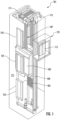
- the elevator system 101 includes an elevator car 103, a counterweight 105, a tension member or tension member 107, a guide rail 109, a machine 111, a position reference system 113 and a controller 115.
- the elevator car 103 and the counterweight 105 are connected to each other by the tension member 107.
- the tension member 107 may include or be configured as, for example, ropes, coated ropes, steel cables and/or coated-steel belts.
- the counterweight 105 is configured to balance a load of the elevator car 103 and is configured to facilitate movement of the elevator car 103 concurrently and in an opposite direction with respect to the counterweight 105 within a hoistway 117 and along the guide rail 109.
- the tension member 107 engages the machine 111, which is part of an overhead structure of the elevator system 101.
- the machine 111 is configured to control movement between the elevator car 103 and the counterweight 105.
- the position reference system 113 may be mounted on a fixed part at the top of the hoistway 117, such as on a support or guide rail, and may be configured to provide position signals related to a position of the elevator car 103 within the hoistway 117. In other embodiments, the position reference system 113 may be directly mounted to a moving component of the machine 111, or may be located in other positions and/or configurations as known in the art.
- the position reference system 113 can be any device or mechanism for monitoring a position of an elevator car and/or counterweight, as known in the art.
- the position reference system 113 can be an encoder, sensor, or other system and can include velocity sensing, absolute position sensing, etc., as will be appreciated by those of skill in the art.
- the controller 115 may be located, as shown, in a controller room 121 of the hoistway 117 and is configured to control the operation of the elevator system 101, and particularly the elevator car 103. It is to be appreciated that the controller 115 need not be in the controller room 121 but may be in the hoistway or other location in the elevator system. For example, the controller 115 may provide drive signals to the machine 111 to control the acceleration, deceleration, leveling, stopping, etc. of the elevator car 103. The controller 115 may also be configured to receive position signals from the position reference system 113 or any other desired position reference device. When moving up or down within the hoistway 117 along guide rail 109, the elevator car 103 may stop at one or more landings 125 as controlled by the controller 115.
- controller 115 can be located and/or configured in other locations or positions within the elevator system 101.
- the controller 115 may be located remotely or in a distributed computing network (e.g., cloud computing architecture).
- the controller 115 may be implemented using a processor-based machine, such as a personal computer, server, distributed computing network, etc.
- the machine 111 may include a motor or similar driving mechanism.
- the machine 111 is configured to include an electrically driven motor.
- the power supply for the motor may be any power source, including a power grid, which, in combination with other components, is supplied to the motor.
- the machine 111 may include a traction sheave that imparts force to the tension member 107 to move the elevator car 103 within hoistway 117.
- the elevator system 101 also includes one or more elevator doors 104.
- the elevator door 104 may be integrally attached to the elevator car 103 or the elevator door 104 may be located on a landing 125 of the elevator system 101, or both. Embodiments disclosed herein may be applicable to both an elevator door 104 integrally attached to the elevator car 103 or an elevator door 104 located on a landing 125 of the elevator system 101, or both.
- the elevator door 104 opens to allow passengers to enter and exit the elevator car 103.
- a monitoring system 201 of an elevator system such as the elevator system 101 of FIG. 1 .
- the monitoring system 201 includes a controller, such as the controller 115, which is configured to control the machine 111 to cause the elevator car 103 to travel to a predefined position (i.e., a landing 125 or a mid-hatch position) in the hoistway 117.
- the controller 115 can be configured to cause the elevator car 103 to travel to the predefined position in response to an instruction to initiate a tension member monitoring control mode being received by the controller 115.
- the monitoring system 201 further includes a sensor 210 (see FIG. 2 ), sensor 310 (see FIG.
- the processor 401 is operably coupled to the sensor 210, 310 and is configured to analyze the data and to calculate, based on analysis results, an elongation of the tension member 107.
- the processor 401 can be further configured to estimate tension member life based on the elongation of the tension member 107.
- the processor 401 can be further configured to shut down the elevator system 101 in an event the tension member life is determined to be less than a shutdown limit.
- the processor 401 can be further configured to issue an alarm in an event the tension member life is less than an alarm limit but not less than the shutdown limit.
- the sensor 210 can be mounted on the elevator car 103 in such a way that a field-of-view (FOV) of the sensor 210 encompasses at least a portion of the counterweight 105 with the elevator car 103 stopped at the predefined position.
- FOV field-of-view
- the sensor 210 can be mounted to a ceiling of the elevator car 103 and aimed downwardly toward the counterweight 105.
- the sensor 310 can be mounted remote from the elevator car 103 in such a way that the FOV of the sensor 310 encompasses at least a portion of the counterweight 105 with the elevator car 103 stopped at the predefined position.
- the sensor 310 can be mounted at or near the ceiling of the hoistway 117 and aimed downwardly toward the counterweight 105.
- the processor 401 includes a processing unit, a memory and an input/output (I/O) unit by which the processor 401 is communicative with the sensor 210, 310 and at least the controller 115 (see FIG. 1 ).
- the memory has executable instructions stored thereon, which are readable and executable by the processing unit. When the processing unit reads and executes the executable instructions, the executable instructions cause the processor to operate as described herein.
- the executable instructions may include a machine-learning algorithm, which improves certain operations of the processing unit over time.
- the processor 401 can be remote from the sensor 210, 310 or local.
- the processor 401 can be operably coupled to the sensor 210, 310 via a wired connection or via a wireless connection.
- the processor 401 can be built into the sensor 210, 310 or provided as a separate component from the sensor 210, 310 and operably coupled to the sensor 210, 310 via a wired connection or via a wireless connection.
- the senor 210, 310 can include or be provided as one or more of a light detection and ranging or a laser imaging, detection, and ranging (LiDAR) sensor, a radio detection and ranging (RADAR) sensor and/or a camera.
- the sensor 210, 310 can be provided as one or more of a 2D LiDAR sensor, a millimeter wave RADAR sensor and/or a red, green, blue, depth (RGBD) camera.
- the sensor 210, 310 can be provided as plural sensors including a combination of one or more sensor types listed herein.
- the senor 210, 310 is configured to sense the plane P in each of FIGS. 2 and 3 as a 2D plane.
- the sensor 210, 310 is configured to generate the data as point cloud data 501 using a single scan for image processing, multiple scans for image processing and/or multiple successive or continuous scans for video processing and the processor 401 is configured to analyze the point cloud data 501 and to determine whether the point cloud data 501 is indicative of the counterweight 105 being in the plane P as evidenced by the point cloud data 501 of FIG. 5A or being at least partially outside of the plane P as evidenced by the point cloud data 501 of FIG. 5B .
- the processor 401 can recognize that the counterweight 105 is at a certain position relative to the elevator car 103 or in the hoistway 117 and that this certain position is not evidence of an elongation of the tension member 107 whereas, for the point cloud data 501 of FIG. 5B , the processor 401 can recognize that the counterweight 105 is at a certain position relative to the elevator car 103 or in the hoistway 117 and that this certain position is evidence of an elongation of the tension member 107.
- a monitoring method 600 is provided for use with an elevator system, such as the elevator system 101 of FIG. 1 , and/or the monitoring system 201 of FIGS. 2-5B .
- the monitoring method 600 includes initially receiving an instruction to initiate a tension member monitoring control mode (601), causing the elevator car to travel to a predefined position in the hoistway in response to the instruction being received (602), sensing a position of the counterweight with the elevator car stopped at the predefined position (603) and generating data corresponding to results of the sensing, analyzing the data and calculating, based on results of the analyzing, an elongation of the tension member (604).
- the sensing of 603 can be executed by a sensor, such as a 2D LiDAR sensor, that is mounted on an elevator car or remotely from the elevator car.
- the monitoring method 600 can further include estimating tension member life based on the elongation (605) and either shutting down the elevator system in an event the tension member life is less than a shutdown limit (606) or issuing an alarm in an event the tension member life is less than an alarm limit but not less than the shutdown limit (607).
- FIG. 7 an operation of a stiffness-based tension member health monitoring system is illustrated.
- an initial drive sheave position and an initial elevator car position can be recorded along with a drive landing torque.
- a current drive sheave position and current elevator car position can be recorded so that a change in length of the tension member can be measured and an effective stiffness of the tension member can be determined.
- the drive holding torque can be used to calculate an actual load weight of the elevator car and that load weight can then be used to update an estimate of the tension member stiffness.
- a stiffness-based tension member health monitoring method 800 is provided for use with an elevator system, such as the elevator system 101 of FIG. 1 and the stiffness-based tension member health monitoring system of FIG. 7 .
- the monitoring method 800 includes calculating a calculated load weight of the elevator car (801), generating, at a load estimator, which is receptive of an estimate of a stiffness of the tension member, an estimated load weight of the elevator car from at least the estimate of the stiffness of the tension member (802) and determining, from a difference between the calculated load weight and the estimated load weight, the estimate of a stiffness of the tension member (803).
- an enabling feature of the "stiffness-based" tension member life monitoring method 800 is the change in load in the elevator at landing and before subsequent take-off is measured (by a direct sensor) or calculated (as shown in this specific embodiment using the change in tension member length from difference of drive sheave position and car position).
- the calculating of the calculated load weight of 801 can be based on landing and holding torques or on a load weight sensor reading.
- the load estimator can be receptive of the estimate of the stiffness of the tension member and one or more of an elevator car landing location, an elevator car position and a sheave position and, in these or other cases, the load estimator generates the estimated load weight of the elevator car from at least the estimate of the stiffness of the tension member and the one or more of the elevator car landing location, the elevator car position and the sheave position.
- the feedback loop in FIG. 8 can be used as part of a learning algorithm to self-calibrate the rope stiffness estimator in a mode that adjusts over time.
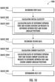
- a monitoring method 900 is provided for use with an elevator system, such as the elevator system 101 of FIG. 1 and/or the monitoring system 201 of FIGS. 2-5B .
- the monitoring method 900 includes recording a baseline weight of the elevator car (block 901), recording, at an initial time, a baseline angular position of the sheave with the elevator car at a known position in the hoistway and at the baseline weight (block 902), recording, at a later time, a current angular position of the sheave with the elevator car at the known position in the hoistway and at the baseline weight (block 903) and transforming a difference between the baseline angular position and the current angular position into a stiffness measurement for the tension belt for use in determining tension belt life (block 904).
- the known position of the elevator car can be a sensed position and can be provided by any of the sensors described above.
- the stiffness measurement can thus be directly proportional to the difference between the baseline angular position and the current angular position (i.e., wherein the difference between the baseline angular position and the current angular position is a percentage of a total angular rotation of the sheave required to move the elevator car from an initial location in the hoistway to the known position).
- the method 900 can be modified for cases in which a weight of the elevator car is known to change over time.
- the method 900 can include measuring a current weight of the elevator car (block 905) and recording, at the later time, a modified current angular position of the sheave with the elevator car at the known position in the hoistway and at the current weight (block 906).
- the transforming of block 904 can include accounting for a difference between the baseline weight and the current weight in calculating the stiffness measurement (block 9041).
- the method can include confirming the stiffness measurement using a change in a characteristic sag-and-bounce of the elevator car over time (block 907), which can be established from data generated at multiple instances of the elevator car becoming occupied (i.e., by a known weight or by people of unknown weights that have to be determined and accounted for in determining the characteristic sag-and-bounce of the elevator car).
- a monitoring method 1000 is provided for use with an elevator system, such as the elevator system 101 of FIG. 1 and/or the monitoring system 201 of FIGS. 2-5B .
- the monitoring method 1000 includes recording, at an initial time, first data points comprising first and second angular positions of the sheave with the elevator car at a known position (i.e., a sensed position) in the hoistway and at first and second elevator car weights, respectively (block 1001), calculating an initial tension belt elasticity from the first data points (block 1002), recording, at a later time, second data points comprising first and second current angular positions of the sheave with the elevator car at the known position in the hoistway and at first and second current elevator car weights, respectively (block 1003), calculating a current tension belt elasticity from the second data points (block 1004) and determining tension belt life from a difference between the initial and current tension belt elasticities (block 1005).
- the calculating of the initial tension belt elasticity from the first data points of block 1002 includes calculating a ratio of a difference between the first and second elevator car weights to a difference between the first and second angular positions (block 10021) and the calculating of the current tension belt elasticity from the second data points of block 1004 includes calculating a ratio of a difference between the first and second current elevator car weights to a difference between the first and second current angular positions (block 10041).
- the second elevator car weight can be a sum of the first elevator car weight and an additional weight and the second current elevator car weight can be a sum of the first current elevator car weight and an additional weight.
- the additional weight can include at least one of passenger and load weights that are sensed by a load weighing sensor or the additional weight can determined from a motor torque change as weights are brought on and off the elevator car.
- Additional technical effects and benefits of the present disclosure are the provision of a system and method for measuring tension member stiffness using readings from various elevator system components. This allows for a determination of belt stiffness using components that are already present in elevator systems and thus presents a cost-effective solution.
Landscapes
- Engineering & Computer Science (AREA)
- Automation & Control Theory (AREA)
- Computer Networks & Wireless Communication (AREA)
- Mechanical Engineering (AREA)
- Maintenance And Inspection Apparatuses For Elevators (AREA)
- Elevator Control (AREA)
Applications Claiming Priority (1)
| Application Number | Priority Date | Filing Date | Title |
|---|---|---|---|
| US18/487,652 US20250122050A1 (en) | 2023-10-16 | 2023-10-16 | Elevator tension member elongation and stiffness monitoring system |
Publications (2)
| Publication Number | Publication Date |
|---|---|
| EP4566980A2 true EP4566980A2 (de) | 2025-06-11 |
| EP4566980A3 EP4566980A3 (de) | 2025-07-09 |
Family
ID=93099817
Family Applications (1)
| Application Number | Title | Priority Date | Filing Date |
|---|---|---|---|
| EP24205952.5A Pending EP4566980A3 (de) | 2023-10-16 | 2024-10-10 | Überwachungssystem für dehnung und steifheit eines zugelements in einem aufzug |
Country Status (3)
| Country | Link |
|---|---|
| US (1) | US20250122050A1 (de) |
| EP (1) | EP4566980A3 (de) |
| CN (1) | CN119841198A (de) |
Family Cites Families (4)
| Publication number | Priority date | Publication date | Assignee | Title |
|---|---|---|---|---|
| WO2019066856A1 (en) * | 2017-09-28 | 2019-04-04 | Kone Corporation | METHOD, ELEVATOR SECURITY CONTROL UNIT AND ELEVATOR SYSTEM FOR DEFINING A STATUS OF AN ELEVATOR CAB SUSPENSION MEANS |
| JP2020040813A (ja) * | 2018-09-12 | 2020-03-19 | 株式会社日立ビルシステム | エレベータークリアランス計測方法 |
| JP7346910B2 (ja) * | 2019-05-28 | 2023-09-20 | 三菱電機ビルソリューションズ株式会社 | クリアランスの測定方法 |
| WO2023275939A1 (ja) * | 2021-06-28 | 2023-01-05 | 三菱電機株式会社 | エレベーターおよびエレベーターの診断方法 |
-
2023
- 2023-10-16 US US18/487,652 patent/US20250122050A1/en active Pending
-
2024
- 2024-10-10 EP EP24205952.5A patent/EP4566980A3/de active Pending
- 2024-10-15 CN CN202411434786.8A patent/CN119841198A/zh active Pending
Also Published As
| Publication number | Publication date |
|---|---|
| CN119841198A (zh) | 2025-04-18 |
| US20250122050A1 (en) | 2025-04-17 |
| EP4566980A3 (de) | 2025-07-09 |
Similar Documents
| Publication | Publication Date | Title |
|---|---|---|
| CN104379480B (zh) | 用于电梯的位置和负载测量系统 | |
| CN102530666B (zh) | 电梯设备 | |
| US6488128B1 (en) | Integrated shaft sensor for load measurement and torque control in elevators and escalators | |
| EP3626668A1 (de) | Überwachung der schwingungssignaturen eines fördersystems | |
| EP3351498A1 (de) | Aufzugschwebemodus mit sensorbasierter potenzieller laständerungsdetektion | |
| CN107922150A (zh) | 电梯控制系统和操作电梯系统的方法 | |
| US11174128B2 (en) | Elevator door control for deboarding passengers in multi-door elevators | |
| US10486935B2 (en) | Elevator diagnosing device | |
| CN111071878B (zh) | 电梯轿厢调平传感器 | |
| CN104220354A (zh) | 电梯 | |
| CN111132921B (zh) | 定义电梯轿厢悬挂装置状况的方法、电梯安全控制单元及电梯系统 | |
| US12280987B2 (en) | Device and method for monitoring an elevator system | |
| EP4566980A2 (de) | Überwachungssystem für dehnung und steifheit eines zugelements in einem aufzug | |
| US20200130994A1 (en) | System for monitoring lobby activity to determine whether to cancel elevator service | |
| EP3901078B1 (de) | Software- oder konfigurations-upgrade für aufzugskomponenten unter verwendung eines kognitiven dienstes | |
| EP3854740B1 (de) | Methode und system zur evakuierung der insassen | |
| US20200055691A1 (en) | Last-minute hall call request to a departing cab using gesture | |
| US11999591B1 (en) | Elevator system including sensor assembly for person detection | |
| US20200346892A1 (en) | Method and apparatus for detecting the position of an elevator | |
| EP4313828B1 (de) | Verfahren und system zur verwendung digitaler zwillinge zur bestimmung des wartungsbedarfs eines aufzugs | |
| EP4477596A1 (de) | Aufzugssystem mit sensoranordnung zur erkennung von objektladung und -entladung | |
| EP4477606A1 (de) | Überwachung des ausgleichsseil-spanners in einer aufzugsgrube | |
| US11964848B1 (en) | Elevator pit monitoring and integrity check of monitoring system | |
| US20240409365A1 (en) | Alignment guide of sensor assembly for person detection | |
| HK40024983A (en) | A method, an elevator safety control unit, and an elevator system for defining a condition of an elevator car suspension means |
Legal Events
| Date | Code | Title | Description |
|---|---|---|---|
| PUAI | Public reference made under article 153(3) epc to a published international application that has entered the european phase |
Free format text: ORIGINAL CODE: 0009012 |
|
| STAA | Information on the status of an ep patent application or granted ep patent |
Free format text: STATUS: THE APPLICATION HAS BEEN PUBLISHED |
|
| PUAL | Search report despatched |
Free format text: ORIGINAL CODE: 0009013 |
|
| AK | Designated contracting states |
Kind code of ref document: A2 Designated state(s): AL AT BE BG CH CY CZ DE DK EE ES FI FR GB GR HR HU IE IS IT LI LT LU LV MC ME MK MT NL NO PL PT RO RS SE SI SK SM TR |
|
| AK | Designated contracting states |
Kind code of ref document: A3 Designated state(s): AL AT BE BG CH CY CZ DE DK EE ES FI FR GB GR HR HU IE IS IT LI LT LU LV MC ME MK MT NL NO PL PT RO RS SE SI SK SM TR |
|
| RIC1 | Information provided on ipc code assigned before grant |
Ipc: B66B 5/00 20060101ALI20250604BHEP Ipc: B66B 7/12 20060101AFI20250604BHEP |
|
| STAA | Information on the status of an ep patent application or granted ep patent |
Free format text: STATUS: REQUEST FOR EXAMINATION WAS MADE |
|
| 17P | Request for examination filed |
Effective date: 20251120 |