EP4566792A1 - Extension rod sliding mechanism, intermediate mold, and mold unit - Google Patents
Extension rod sliding mechanism, intermediate mold, and mold unit Download PDFInfo
- Publication number
- EP4566792A1 EP4566792A1 EP24204089.7A EP24204089A EP4566792A1 EP 4566792 A1 EP4566792 A1 EP 4566792A1 EP 24204089 A EP24204089 A EP 24204089A EP 4566792 A1 EP4566792 A1 EP 4566792A1
- Authority
- EP
- European Patent Office
- Prior art keywords
- extension rod
- extension
- axial direction
- mold
- gap
- Prior art date
- Legal status (The legal status is an assumption and is not a legal conclusion. Google has not performed a legal analysis and makes no representation as to the accuracy of the status listed.)
- Pending
Links
Images
Classifications
-
- B—PERFORMING OPERATIONS; TRANSPORTING
- B29—WORKING OF PLASTICS; WORKING OF SUBSTANCES IN A PLASTIC STATE IN GENERAL
- B29C—SHAPING OR JOINING OF PLASTICS; SHAPING OF MATERIAL IN A PLASTIC STATE, NOT OTHERWISE PROVIDED FOR; AFTER-TREATMENT OF THE SHAPED PRODUCTS, e.g. REPAIRING
- B29C49/00—Blow-moulding, i.e. blowing a preform or parison to a desired shape within a mould; Apparatus therefor
- B29C49/02—Combined blow-moulding and manufacture of the preform or the parison
- B29C49/06—Injection blow-moulding
- B29C49/061—Injection blow-moulding with parison holding means displaceable between injection and blow stations
- B29C49/062—Injection blow-moulding with parison holding means displaceable between injection and blow stations following an arcuate path, e.g. rotary or oscillating-type
- B29C49/063—Injection blow-moulding with parison holding means displaceable between injection and blow stations following an arcuate path, e.g. rotary or oscillating-type with the parison axis held in the plane of rotation
-
- B—PERFORMING OPERATIONS; TRANSPORTING
- B29—WORKING OF PLASTICS; WORKING OF SUBSTANCES IN A PLASTIC STATE IN GENERAL
- B29C—SHAPING OR JOINING OF PLASTICS; SHAPING OF MATERIAL IN A PLASTIC STATE, NOT OTHERWISE PROVIDED FOR; AFTER-TREATMENT OF THE SHAPED PRODUCTS, e.g. REPAIRING
- B29C49/00—Blow-moulding, i.e. blowing a preform or parison to a desired shape within a mould; Apparatus therefor
- B29C49/42—Component parts, details or accessories; Auxiliary operations
- B29C49/58—Blowing means
- B29C49/60—Blow-needles
-
- B—PERFORMING OPERATIONS; TRANSPORTING
- B29—WORKING OF PLASTICS; WORKING OF SUBSTANCES IN A PLASTIC STATE IN GENERAL
- B29C—SHAPING OR JOINING OF PLASTICS; SHAPING OF MATERIAL IN A PLASTIC STATE, NOT OTHERWISE PROVIDED FOR; AFTER-TREATMENT OF THE SHAPED PRODUCTS, e.g. REPAIRING
- B29C49/00—Blow-moulding, i.e. blowing a preform or parison to a desired shape within a mould; Apparatus therefor
- B29C49/42—Component parts, details or accessories; Auxiliary operations
- B29C49/48—Moulds
-
- B—PERFORMING OPERATIONS; TRANSPORTING
- B29—WORKING OF PLASTICS; WORKING OF SUBSTANCES IN A PLASTIC STATE IN GENERAL
- B29C—SHAPING OR JOINING OF PLASTICS; SHAPING OF MATERIAL IN A PLASTIC STATE, NOT OTHERWISE PROVIDED FOR; AFTER-TREATMENT OF THE SHAPED PRODUCTS, e.g. REPAIRING
- B29C45/00—Injection moulding, i.e. forcing the required volume of moulding material through a nozzle into a closed mould; Apparatus therefor
- B29C45/03—Injection moulding apparatus
- B29C45/04—Injection moulding apparatus using movable moulds or mould halves
- B29C45/0441—Injection moulding apparatus using movable moulds or mould halves involving a rotational movement
- B29C45/045—Injection moulding apparatus using movable moulds or mould halves involving a rotational movement mounted on the circumference of a rotating support having a rotating axis perpendicular to the mould opening, closing or clamping direction
-
- B—PERFORMING OPERATIONS; TRANSPORTING
- B29—WORKING OF PLASTICS; WORKING OF SUBSTANCES IN A PLASTIC STATE IN GENERAL
- B29C—SHAPING OR JOINING OF PLASTICS; SHAPING OF MATERIAL IN A PLASTIC STATE, NOT OTHERWISE PROVIDED FOR; AFTER-TREATMENT OF THE SHAPED PRODUCTS, e.g. REPAIRING
- B29C49/00—Blow-moulding, i.e. blowing a preform or parison to a desired shape within a mould; Apparatus therefor
- B29C49/08—Biaxial stretching during blow-moulding
- B29C49/10—Biaxial stretching during blow-moulding using mechanical means for prestretching
- B29C49/12—Stretching rods
-
- B—PERFORMING OPERATIONS; TRANSPORTING
- B29—WORKING OF PLASTICS; WORKING OF SUBSTANCES IN A PLASTIC STATE IN GENERAL
- B29C—SHAPING OR JOINING OF PLASTICS; SHAPING OF MATERIAL IN A PLASTIC STATE, NOT OTHERWISE PROVIDED FOR; AFTER-TREATMENT OF THE SHAPED PRODUCTS, e.g. REPAIRING
- B29C49/00—Blow-moulding, i.e. blowing a preform or parison to a desired shape within a mould; Apparatus therefor
- B29C49/42—Component parts, details or accessories; Auxiliary operations
- B29C49/4205—Handling means, e.g. transfer, loading or discharging means
- B29C49/42065—Means specially adapted for transporting preforms
-
- B—PERFORMING OPERATIONS; TRANSPORTING
- B29—WORKING OF PLASTICS; WORKING OF SUBSTANCES IN A PLASTIC STATE IN GENERAL
- B29C—SHAPING OR JOINING OF PLASTICS; SHAPING OF MATERIAL IN A PLASTIC STATE, NOT OTHERWISE PROVIDED FOR; AFTER-TREATMENT OF THE SHAPED PRODUCTS, e.g. REPAIRING
- B29C49/00—Blow-moulding, i.e. blowing a preform or parison to a desired shape within a mould; Apparatus therefor
- B29C49/42—Component parts, details or accessories; Auxiliary operations
- B29C49/4205—Handling means, e.g. transfer, loading or discharging means
- B29C49/42069—Means explicitly adapted for transporting blown article
-
- B—PERFORMING OPERATIONS; TRANSPORTING
- B29—WORKING OF PLASTICS; WORKING OF SUBSTANCES IN A PLASTIC STATE IN GENERAL
- B29C—SHAPING OR JOINING OF PLASTICS; SHAPING OF MATERIAL IN A PLASTIC STATE, NOT OTHERWISE PROVIDED FOR; AFTER-TREATMENT OF THE SHAPED PRODUCTS, e.g. REPAIRING
- B29C49/00—Blow-moulding, i.e. blowing a preform or parison to a desired shape within a mould; Apparatus therefor
- B29C49/42—Component parts, details or accessories; Auxiliary operations
- B29C49/58—Blowing means
-
- B—PERFORMING OPERATIONS; TRANSPORTING
- B29—WORKING OF PLASTICS; WORKING OF SUBSTANCES IN A PLASTIC STATE IN GENERAL
- B29C—SHAPING OR JOINING OF PLASTICS; SHAPING OF MATERIAL IN A PLASTIC STATE, NOT OTHERWISE PROVIDED FOR; AFTER-TREATMENT OF THE SHAPED PRODUCTS, e.g. REPAIRING
- B29C49/00—Blow-moulding, i.e. blowing a preform or parison to a desired shape within a mould; Apparatus therefor
- B29C49/42—Component parts, details or accessories; Auxiliary operations
- B29C49/48—Moulds
- B29C2049/4879—Moulds characterised by mould configurations
-
- B—PERFORMING OPERATIONS; TRANSPORTING
- B29—WORKING OF PLASTICS; WORKING OF SUBSTANCES IN A PLASTIC STATE IN GENERAL
- B29C—SHAPING OR JOINING OF PLASTICS; SHAPING OF MATERIAL IN A PLASTIC STATE, NOT OTHERWISE PROVIDED FOR; AFTER-TREATMENT OF THE SHAPED PRODUCTS, e.g. REPAIRING
- B29C49/00—Blow-moulding, i.e. blowing a preform or parison to a desired shape within a mould; Apparatus therefor
- B29C49/42—Component parts, details or accessories; Auxiliary operations
- B29C49/48—Moulds
- B29C2049/4879—Moulds characterised by mould configurations
- B29C2049/4894—With at least a part of the mould cavity formed by a cylindrical mould
-
- B—PERFORMING OPERATIONS; TRANSPORTING
- B29—WORKING OF PLASTICS; WORKING OF SUBSTANCES IN A PLASTIC STATE IN GENERAL
- B29C—SHAPING OR JOINING OF PLASTICS; SHAPING OF MATERIAL IN A PLASTIC STATE, NOT OTHERWISE PROVIDED FOR; AFTER-TREATMENT OF THE SHAPED PRODUCTS, e.g. REPAIRING
- B29C49/00—Blow-moulding, i.e. blowing a preform or parison to a desired shape within a mould; Apparatus therefor
- B29C49/42—Component parts, details or accessories; Auxiliary operations
- B29C49/58—Blowing means
- B29C49/60—Blow-needles
- B29C2049/6072—Blow-needles being movable, e.g. blow needles move to pierce the parison
-
- B—PERFORMING OPERATIONS; TRANSPORTING
- B29—WORKING OF PLASTICS; WORKING OF SUBSTANCES IN A PLASTIC STATE IN GENERAL
- B29L—INDEXING SCHEME ASSOCIATED WITH SUBCLASS B29C, RELATING TO PARTICULAR ARTICLES
- B29L2031/00—Other particular articles
- B29L2031/712—Containers; Packaging elements or accessories, Packages
Definitions
- the present invention relates to an extension rod sliding mechanism, an intermediate mold, and a mold unit.
- injection blow molding which is a molding technique in which injection molding and blow molding are performed in two stages
- a preform which is an intermediate molding product
- a product such as a container
- blowing air into the preform and expanding the preform through the blow molding In the blow molding of injection blow molding, an extension rod, of which one end is joined to an extension plate and the other penetrates a through-hole of a blow core, slides in the through-hole of the blow core together with the movement of the extension plate, and air is blown by causing a tip part to enter the preform (for example, Japanese Patent No. 4425750 ).
- the through-hole of the blow core guides the extension rod that operates in an axial direction.
- the operation of the extension rod joined to the extension plate also becomes unstable, resulting in "core shift" that causes uneven thickness, gate shift, or the like in which the thickness of a molding product becomes uneven.
- the blow core and the extension rod rub against each other to generate abrasion powder or to cause gnawing of the mold in some cases. Therefore, it is desirable that the operation of the extension plate and the operation of the extension rod are more stable.
- An object of the present invention is to further stabilize the operation of the extension rod sliding in the through-hole formed in the blow core.
- an extension rod sliding mechanism including an extension rod that outputs a fluid, which extends an intermediate molding product through blow molding, from a tip part, an extension plate that is joined to the extension rod and that moves in an axial direction of the extension rod, a blow core portion in which a through-hole for guiding the extension rod that moves in the axial direction with a movement of the extension plate is formed, and a guide member that penetrates the extension plate in the axial direction of the extension rod and that guides the extension plate moving in the axial direction of the extension rod.
- the guide member may be a columnar member of which both ends are fixed.
- a first gap determined in advance may be formed between the extension rod and the blow core portion in the through-hole, in a portion where the guide member penetrates the extension plate, a second gap determined in advance may be formed between the guide member and the extension plate, and in a joining portion between the extension rod and the extension plate, a third gap that is a play may be formed.
- each of the first gap and the second gap may be smaller than the third gap.
- an intermediate mold including an extension rod sliding mechanism, in which the extension rod sliding mechanism includes an extension rod that outputs a fluid, which extends an intermediate molding product through blow molding, from a tip part, an extension plate that is joined to the extension rod and that moves in an axial direction of the extension rod, a blow core portion in which a through-hole for guiding the extension rod that moves in the axial direction with a movement of the extension plate is formed, and a guide member that penetrates the extension plate in the axial direction of the extension rod and that guides the extension plate moving in the axial direction of the extension rod.
- a mold unit including a stationary side mold, an intermediate mold that includes an extension rod sliding mechanism, and a movable side mold, in which the extension rod sliding mechanism of the intermediate mold includes an extension rod that outputs a fluid, which extends an intermediate molding product through blow molding, from a tip part, an extension plate that is joined to the extension rod and that moves in an axial direction of the extension rod, a blow core portion in which a through-hole for guiding the extension rod that moves in the axial direction with a movement of the extension plate is formed, and a guide member that penetrates the extension plate in the axial direction of the extension rod and that guides the extension plate moving in the axial direction of the extension rod.
- the operation of the extension rod sliding in the through-hole formed in the blow core can be further stabilized.
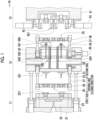
- Fig. 1 is a view showing an example of a configuration of a part of a mold unit 10 including an intermediate mold 12 to which an extension rod sliding mechanism 100 according to the present embodiment is applied.
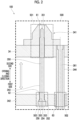
- Fig. 2 is a view showing an example of a configuration of a part of the extension rod sliding mechanism 100.
- Fig. 2 is an enlarged view of a region 500 surrounded by a broken line in Fig. 1 described above.
- the mold unit 10 shown in Fig. 1 is a mold unit that configures an injection molding machine which performs injection blow molding.
- the injection blow molding refers to a molding technique in which injection molding and blow molding are performed in two stages.
- a preform (not shown), which is an intermediate molding product, is molded through injection molding, and a container or the like, which is a final molding product, is molded by blowing high-pressure air into the preform and expanding the preform through blow molding.
- an extension rod 343 to be described later which can output the high-pressure air, is caused to protrude into the preform.
- a direction in which the extension rod 343 protrudes into the preform is a direction from the left side of the drawing to the right side of the drawing in Fig. 1 , an axial direction of the extension rod 343, and an opening and closing direction of the mold unit.
- the direction in which the extension rod 343 protrudes into the preform (a right-left direction in the drawing of Fig. 1 ) will be called an "axial direction” or an "opening and closing direction”.
- the left side of the drawing in Fig. 1 is called a "first side in the opening and closing direction”
- a right side of the drawing in Fig. 1 is called a "second side in the opening and closing direction”.
- the mold unit 10 is configured to include a stationary side mold 11, the intermediate mold 12, and a movable side mold 13.
- the mold unit 10 performs injection molding through mold closing of the intermediate mold 12 and the stationary side mold 11.
- the mold unit 10 performs blow molding through mold closing of the intermediate mold 12 and the movable side mold 13.
- the stationary side mold 11 configuring the mold unit 10 includes a stationary platen 21, a stationary mold 22, and a drive unit 23.
- the stationary platen 21 is a metal member that supports the stationary mold 22.
- the stationary mold 22 is a mold that performs injection molding and includes an injection cavity 221.
- an injection unit (not shown) that injects a molten resin, which is a material for a preform subjected to injection molding, is installed on the second side of the stationary platen 21, which is a device moving the intermediate mold 12 in the opening and closing direction with respect to the stationary platen 21, in the opening and closing direction.
- the intermediate mold 12 configuring the mold unit 10 is a so-called rotating mold disposed between the stationary side mold 11 and the movable side mold 13.
- the intermediate mold 12 performs mold closing and mold opening at a position facing each of the stationary side mold 11 and the movable side mold 13.
- the intermediate mold 12 rotates with a direction perpendicular to the opening and closing direction as a rotation axis and includes a rotating frame 31 that rotates on an outer side of a shaft body 38 in a peripheral direction of the shaft body 38 and a support frame 32 that supports the shaft body 38.
- the intermediate mold 12 includes an injection core 331 that is a core in injection molding, an injection core frame 33 that supports the injection core 331, a blow core 341 that is a core in blow molding, and a blow core frame 34 that supports the blow core 341.
- the intermediate mold 12 includes an extension plate 342 that moves in the opening and closing direction, the extension rod 343 that moves in the opening and closing direction together with the movement of the extension plate 342, and a guide rod 344 that guides the movement of the extension plate 342.
- the intermediate mold 12 includes a gripping mechanism 35 that rotates together with the rotating frame 31, a sliding frame 36, and a guide bar 37.
- the intermediate mold 12 includes the shaft body 38 that includes a center axis in a direction perpendicular to the axial direction of the extension rod 343 and a drive unit 39 that rotates the rotating frame 31.
- the blow core frame 34 configuring the intermediate mold 12 is a part of a blow core portion and is a metal member that supports the blow core 341 through welding or the like. Inside the blow core frame 34, the extension plate 342, the extension rod 343, and the guide rod 344 are disposed.
- the blow core frame 34, the blow core 341, the extension plate 342, the extension rod 343, and the guide rod 344 function as elements that configure the extension rod sliding mechanism 100 according to the present embodiment.
- the blow core 341 that configures the intermediate mold 12 is a part of the blow core portion, is a mold member that is a core in blow molding, and when the mold unit 10 is closed, comes into close contact with a blow cavity 421 of a movable split mold 42 that is openable and closable in the direction perpendicular to the opening and closing direction of the mold unit 10, forming an injection molding space.
- the blow core 341 is separated from the blow cavity 421 of the movable split mold 42.
- Fig. 1 shows a state where the mold unit 10 is opened. For this reason, the blow core 341 is separated from the blow cavity 421, and the movable split mold 42 is also opened.
- the extension plate 342 configuring the intermediate mold 12 is a metal plate that is installed to be movable in the opening and closing direction (the axial direction of the extension rod 343) inside the blow core frame 34.
- An end portion 352 of the extension rod 343 on the first side in the opening and closing direction (axial direction) is joined to the extension plate 342. For this reason, when the extension plate 342 moves in the opening and closing direction (axial direction), the extension rod 343 also moves in the opening and closing direction (the axial direction of the extension rod 343) accordingly.
- each of a plurality of extension rods 343 is joined to the extension plate 342, the plurality of extension rods 343 can be moved in the opening and closing direction (axial direction) simultaneously by moving the extension plate 342 in the opening and closing direction (the axial direction of the extension rod 343).
- the extension plate 342 operates by using a drive unit (not shown) configured by a pneumatic cylinder device or the like as a drive source and moves in the opening and closing direction (the axial direction of the extension rod 343).
- the extension rod 343 configuring the intermediate mold 12 is a metal member that can output high-pressure air for extending a preform through blow molding from a tip part 351.
- the end portion 352 on an opposite side to the tip part 351 of the extension rod 343 is joined to the extension plate 342. For this reason, when the extension plate 342 moves toward the second side in opening and closing direction (the axial direction of the extension rod 343), the extension rod 343 moves toward the second side in the opening and closing direction (axial direction) accordingly, and the tip part 351 protrudes into the preform.
- a technique of joining the extension rod 343 to the extension plate 342 will be described.
- a through-hole 62 formed of a small-diameter portion 354, a medium-diameter portion 355, and a large-diameter portion 356 are formed in the extension plate 342 gradually from the second side toward the first side in the opening and closing direction (the axial direction of the extension rod 343).
- the diameter of a main body 350 of the extension rod 343 is smaller than the diameter of the small-diameter portion 354.
- the end portion 352 of the extension rod 343 has a flange shape.
- the diameter of the flange portion of the end portion 352 is larger than the diameter of the small-diameter portion 354, but is smaller than the diameter of each of the medium-diameter portion 355 and the large-diameter portion 356.
- the extension rod 343 When the extension rod 343 penetrates the through-hole 62 from the first side toward the second side in the opening and closing direction (the axial direction of the extension rod 343), the flange portion of the end portion 352 cannot penetrate the small-diameter portion 354 and remains in the medium-diameter portion 355. In this case, the extension rod 343 is in a free state on the first side in the opening and closing direction (axial direction). Accordingly, a metal block member 353 is buried in a space formed in the large-diameter portion 356. Accordingly, the extension rod 343 is in a state of being fixed in the opening and closing direction (axial direction). In this manner, the extension rod 343 is joined to the extension plate 342.
- the guide rod 344 configuring the intermediate mold 12 is a columnar metal member of which both ends are fixed in a state of penetrating a through-hole 63 formed in the extension plate 342 in the opening and closing direction (the axial direction of the extension rod 343).
- an end portion of the guide rod 344 on the first side in the opening and closing direction (axial direction) is fixed to the injection core frame 33, and an end portion thereof on the second side in the opening and closing direction (axial direction) is fixed to the blow core frame 34.
- the guide rod 344 functions as a guide member that guides the extension plate 342 moving in the opening and closing direction (the axial direction of the extension rod 343).
- a technique of fixing both ends of the guide rod 344 is not particularly limited.
- the guide rod 344 need only be firmly fixed not to be rattled.
- the guide rod 344 may be fixed using a bolt or may be fixed through welding.
- both ends of the guide rod 344 are fixed to the injection core frame 33 and the blow core frame 34 (see Fig. 1 ) using a bolt 361 penetrating the guide rod 344 in a longitudinal direction (opening and closing direction) (see Fig. 2 ).
- a male screw formed at an end portion of the bolt 361 on the first side in the opening and closing direction and a female screw formed at a surface of the injection core frame 33 on the second side in opening and closing direction are combined with each other, so that an end portion of the guide rod 344 on the first side in the opening and closing direction is fixed to the injection core frame 33.
- the gripping mechanism 35 that configures the intermediate mold 12 is a mechanism that grips an outer periphery of a mouth portion of a preform and a final molding product.
- the sliding frame 36 configuring the intermediate mold 12 is a member that is slidably attached in an axial direction of the guide bar 37 and supports the gripping mechanism 35. When the sliding frame 36 slides on the guide bar 37, the gripping mechanism 35 moves together with the sliding frame 36.
- the guide bar 37 that configures the intermediate mold 12 is a columnar member of which one end is fixed to the rotating frame 31, and the sliding frame 36 is slidably attached to the other end side. The guide bar 37 guides the sliding of the sliding frame 36.
- the shaft body 38 that configures the intermediate mold 12 is a tubular metal member joined to the support frame 32, the injection core frame 33, and the blow core frame 34.
- the drive unit 39 that configures the intermediate mold 12 is a device that is a drive source for rotating the rotating frame 31 and is configured by, for example, a motor or the like. When the rotating frame 31 rotates, the guide bar 37, the sliding frame 36, and the gripping mechanism 35 rotate together and alternately move to a position where injection molding is performed and a position where blow molding is performed.
- the movable side mold 13 that configures the mold unit 10 includes a movable platen 41, a movable split mold 42, and a drive unit 43.
- the movable platen 41 is a metal member that supports the movable split mold 42.
- a mold clamping unit (not shown) that performs mold closing and mold opening of the mold unit 10 is installed on the second side in the opening and closing direction with respect to the movable platen 41.
- the movable split mold 42 is a split mold that is a mold which performs blow molding and includes the blow cavity 421.
- the drive unit 43 is a device that is a drive source for opening and closing the movable split mold 42 in the opening and closing direction.
- the mold unit 10 forms a final molding product such as a container by causing the extension rod 343 to protrude into a preform and blowing high-pressure air to extend the preform as blow molding on the preform which is injection-molded.
- a final molding product such as a container by causing the extension rod 343 to protrude into a preform and blowing high-pressure air to extend the preform as blow molding on the preform which is injection-molded.
- the extension rod sliding mechanism 100 described above functions.
- An air flow path (not shown), an air output hole (not shown), or the like for supplying high-pressure air used in blow molding is formed in the blow core 341, the extension rod 343, or therebetween.
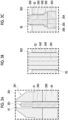
- Figs. 3A to 3C are views showing positions of gaps formed in the extension rod sliding mechanism 100.
- Fig. 3A is an enlarged view of a region 501 surrounded by the broken line in Fig. 2 described above and shows the position of a first gap 51 formed between the extension rod 343, and the blow core 341 and the blow core frame 34.
- Fig. 3B is an enlarged view of a region 502 surrounded by the broken line in Fig. 2 described above and shows the position of a second gap 52 formed between the guide rod 344 and the extension plate 342.
- Fig. 3C is an enlarged view of a region 503 surrounded by the broken line in Fig. 2 described above and shows the position of a third gap 53 formed between the extension rod 343 and the extension plate 342.
- the first gap 51 is formed between the extension rod 343, and the blow core 341 and the blow core frame 34, and the first gap 51 allows the extension rod 343 to slide in the through-hole 61.
- a structure that forms the first gap 51 is a structure that is designed so that the size of the first gap 51 falls in a range determined in advance. Specifically, the diameter of the main body 350 of the extension rod 343 is designed to be slightly smaller than the diameter of the through-hole 61.
- the second gap 52 is formed between the guide rod 344 and the extension plate 342, and the second gap 52 allows the extension plate 342 to slide with respect to the guide rod 344.
- a structure that forms the second gap 52 is a structure that is designed so that the size of the second gap 52 falls in a range determined in advance.
- the diameter of the guide rod 344 is designed to be slightly smaller than the diameter of the through-hole 63 formed in the extension plate 342.
- the third gap 53 is formed between the extension rod 343 and the extension plate 342, and the third gap 53 functions as a play of the extension rod 343 with respect to the extension plate 342.
- a structure that forms the third gap 53 is a structure that is designed so that the size of the third gap 53 falls in a range determined in advance.
- the diameter of the main body 350 of the extension rod 343 is designed to be slightly smaller than the diameter of the small-diameter portion 354 of the through-hole 62 formed in the extension plate 342.
- a difference between the diameter of the guide rod 344 and the diameter of the through-hole 63 is designed to be smaller than the difference between the diameter of the main body 350 of the extension rod 343 and the diameter of the small-diameter portion 354 of the through-hole 62.
- a relationship between the structure for forming the first gap 51 and the structure for forming the second gap 52 is a relationship of restricting each other.
- the third gap 53 which is a play, is formed, a restriction on the structure for forming the first gap 51 and a restriction on the structure for forming the second gap 52 are compatible with each other.
- the third gap 53 which is a play is formed, and thus, the first gap 51 for stably sliding the extension rod 343 in the opening and closing direction (axial direction) and the second gap 52 for stably moving the extension plate 342 in the opening and closing direction (the axial direction of the extension rod 343) are secured.
- extension rod sliding mechanism the intermediate mold, and the mold unit to which the present invention is applied need only adopt the following configuration, and various types of embodiments can be adopted.
- the extension rod sliding mechanism 100 is an extension rod sliding mechanism including the extension rod 343 that outputs a fluid (for example, high-pressure air) which extends a preform, which is an intermediate molding product, through blow molding, from the tip part 351, the extension plate 342 that is joined to the extension rod 343 and that moves in the axial direction of the extension rod 343, the blow core 341 and the blow core frame 34 in which the through-hole 61 for guiding the extension rod 343 that moves in the axial direction with the movement of the extension plate 342 is formed, and the guide rod 344 that is a guide member which penetrates the extension plate 342 in the axial direction of the extension rod 343 and which guides the extension plate 342 moving in the axial direction of the extension rod 343.
- a fluid for example, high-pressure air
- the guide rod 344 that penetrates the extension plate 342 in the axial direction of the extension rod 343 guides the extension plate 342 that moves in the axial direction of the extension rod 343. Therefore, an operation of the extension plate 342 and an operation of the extension rod 343 joined to the extension plate 342 can be stabilized.
- "core shift" that causes uneven thickness, gate shift, or the like is suppressed, and generation of abrasion powder caused by the blow core 341, the blow core frame 34, and the extension rod 343 rubbing against each other or occurrence of gnawing of the mold is suppressed.
- the guide rod 344 may be a columnar member of which both ends are fixed.
- the guide rod 344 which is a columnar member having both ends fixed, guides the extension plate 342 moving in the axial direction of the extension rod 343. Therefore, the operation of the extension plate 342 can be stabilized. As a result, the operation of the extension rod 343 joined to the extension plate 342 can be stabilized.
- the structure for forming the first gap 51 required for the sliding of the extension rod 343, the structure for forming the second gap 52 required for the sliding of the guide rod 344, and the structure for forming the third gap 53 which is a play For this reason, for example, even when the structure for forming the first gap 51 and the structure for forming the second gap 52 are in a relationship of restricting each other, the third gap 53, which is a play, is formed. Therefore, a restriction on the structure for forming the first gap 51 and a restriction on the structure for forming the second gap 52 can be made compatible with each other.
- the first gap 51 for stably sliding the extension rod 343 and the second gap 52 for stably moving the extension plate 342 in the axial direction (opening and closing direction) of the extension rod 343 can be formed.
- the third gap 53, which is a play, is formed assembly for joining the extension rod 343 and the extension plate 342 can be simplified.
- each of the first gap 51 and the second gap 52 may be smaller than the third gap 53.
- each of the first gap 51 and the second gap 52 is smaller than the third gap 53, the structure for forming the first gap 51 and the structure for forming the second gap 52 are in a relationship of restricting each other.
- the third gap 53 can be made large so that a restriction on the structure for forming the first gap 51 and a restriction on the structure for forming the second gap 52 are compatible with each other.
- the first gap 51 for stably sliding the extension rod 343 and the second gap 52 for stably moving the extension plate 342 in the axial direction (opening and closing direction) of the extension rod 343 can be formed.
- the third gap 53 which is a play, is formed, assembly for joining the extension rod 343 and the extension plate 342 can be simplified.
- the intermediate mold to which the present invention is applied need only adopt the following configuration, and various embodiments can be adopted.
- the intermediate mold 12 is the intermediate mold 12 including the extension rod sliding mechanism 100.
- the extension rod sliding mechanism 100 includes the extension rod 343 that outputs a fluid which extends a preform, which is an intermediate molding product, through blow molding from the tip part 351, the extension plate 342 that is joined to the extension rod 343 and that moves in the axial direction of the extension rod 343, the blow core 341 and the blow core frame 34 in which the through-hole 61 for guiding the extension rod 343 that moves in the axial direction with the movement of the extension plate 342 is formed, and the guide rod 344 that is a guide member which penetrates the extension plate 342 in the axial direction of the extension rod 343 and which guides the extension plate 342 moving in the axial direction of the extension rod 343.
- the guide rod 344 that penetrates the extension plate 342 in the axial direction of the extension rod 343 guides the extension plate 342 that moves in the axial direction of the extension rod 343. Therefore, an operation of the extension plate 342 and an operation of the extension rod 343 joined to the extension plate 342 can be stabilized.
- "core shift" that causes uneven thickness, gate shift, or the like is suppressed, and generation of abrasion powder caused by the blow core 341, the blow core frame 34, and the extension rod 343 rubbing against each other or occurrence of gnawing of the mold is suppressed.
- the mold unit to which the present invention is applied need only adopt the following configuration, and various embodiments can be adopted.
- the mold unit 10 is a mold unit including the stationary side mold 11, the intermediate mold 12 that includes the extension rod sliding mechanism 100, and the movable side mold 13.
- the extension rod sliding mechanism 100 of the intermediate mold 12 includes the extension rod 343 that outputs a fluid which extends a preform, which is an intermediate molding product, through blow molding from the tip part 351, the extension plate 342 that is joined to the extension rod 343 and that moves in the axial direction of the extension rod 343, the blow core 341 and the blow core frame 34 in which the through-hole 61 for guiding the extension rod 343 that moves in the axial direction with the movement of the extension plate 342 is formed, and the guide rod 344 that is a guide member which penetrates the extension plate 342 in the axial direction of the extension rod 343 and which guides the extension plate 342 moving in the axial direction of the extension rod 343.
- the guide rod 344 that penetrates the extension plate 342 in the axial direction of the extension rod 343 guides the extension plate 342 that moves in the axial direction of the extension rod 343. Therefore, an operation of the extension plate 342 and an operation of the extension rod 343 joined to the extension plate 342 can be stabilized.
- "core shift" that causes uneven thickness, gate shift, or the like is suppressed, and generation of abrasion powder caused by the blow core 341, the blow core frame 34, and the extension rod 343 rubbing against each other or occurrence of gnawing of the mold is suppressed.
- the present invention is not limited to the embodiment described above.
- the effects of the present invention are also not limited to those described in the embodiment described above.
- the configuration of the mold unit 10 shown in Fig. 1 the configuration of the extension rod sliding mechanism 100 shown in Fig. 2 , and the positions of the gaps shown in Figs. 3A to 3C are merely examples for achieving the object of the present invention and are not particularly limited.
- the number of the guide rods 344 is not limited.
- the number of the guide rods 344 may be one or may be three or more.
Landscapes
- Engineering & Computer Science (AREA)
- Manufacturing & Machinery (AREA)
- Mechanical Engineering (AREA)
- Moulds For Moulding Plastics Or The Like (AREA)
- Blow-Moulding Or Thermoforming Of Plastics Or The Like (AREA)
Abstract
Description
- The present invention relates to an extension rod sliding mechanism, an intermediate mold, and a mold unit.
- In injection blow molding, which is a molding technique in which injection molding and blow molding are performed in two stages, a preform, which is an intermediate molding product, is molded through the injection molding, and a product such as a container is molded by blowing air into the preform and expanding the preform through the blow molding. In the blow molding of injection blow molding, an extension rod, of which one end is joined to an extension plate and the other penetrates a through-hole of a blow core, slides in the through-hole of the blow core together with the movement of the extension plate, and air is blown by causing a tip part to enter the preform (for example,
Japanese Patent No. 4425750 - The through-hole of the blow core guides the extension rod that operates in an axial direction. However, when a certain force is applied to the extension plate and the operation becomes unstable, the operation of the extension rod joined to the extension plate also becomes unstable, resulting in "core shift" that causes uneven thickness, gate shift, or the like in which the thickness of a molding product becomes uneven. Further, the blow core and the extension rod rub against each other to generate abrasion powder or to cause gnawing of the mold in some cases. Therefore, it is desirable that the operation of the extension plate and the operation of the extension rod are more stable.
- An object of the present invention is to further stabilize the operation of the extension rod sliding in the through-hole formed in the blow core.
- According to an aspect of the present invention devised for such an object, there is provided an extension rod sliding mechanism including an extension rod that outputs a fluid, which extends an intermediate molding product through blow molding, from a tip part, an extension plate that is joined to the extension rod and that moves in an axial direction of the extension rod, a blow core portion in which a through-hole for guiding the extension rod that moves in the axial direction with a movement of the extension plate is formed, and a guide member that penetrates the extension plate in the axial direction of the extension rod and that guides the extension plate moving in the axial direction of the extension rod.
- Herein, the guide member may be a columnar member of which both ends are fixed.
- In addition, a first gap determined in advance may be formed between the extension rod and the blow core portion in the through-hole, in a portion where the guide member penetrates the extension plate, a second gap determined in advance may be formed between the guide member and the extension plate, and in a joining portion between the extension rod and the extension plate, a third gap that is a play may be formed.
- In addition, each of the first gap and the second gap may be smaller than the third gap.
- In addition, according to another aspect of the present invention, there is provided an intermediate mold including an extension rod sliding mechanism, in which the extension rod sliding mechanism includes an extension rod that outputs a fluid, which extends an intermediate molding product through blow molding, from a tip part, an extension plate that is joined to the extension rod and that moves in an axial direction of the extension rod, a blow core portion in which a through-hole for guiding the extension rod that moves in the axial direction with a movement of the extension plate is formed, and a guide member that penetrates the extension plate in the axial direction of the extension rod and that guides the extension plate moving in the axial direction of the extension rod.
- In addition, according to still another aspect of the present invention, there is provided a mold unit including a stationary side mold, an intermediate mold that includes an extension rod sliding mechanism, and a movable side mold, in which the extension rod sliding mechanism of the intermediate mold includes an extension rod that outputs a fluid, which extends an intermediate molding product through blow molding, from a tip part, an extension plate that is joined to the extension rod and that moves in an axial direction of the extension rod, a blow core portion in which a through-hole for guiding the extension rod that moves in the axial direction with a movement of the extension plate is formed, and a guide member that penetrates the extension plate in the axial direction of the extension rod and that guides the extension plate moving in the axial direction of the extension rod.
- According to the present invention, the operation of the extension rod sliding in the through-hole formed in the blow core can be further stabilized.
-
-
Fig. 1 is a view showing an example of a configuration of a part of a mold unit including an intermediate mold to which an extension rod sliding mechanism according to the present embodiment is applied. -
Fig. 2 is a view showing an example of a configuration of a part of the extension rod sliding mechanism. -
Figs. 3A to 3C are views showing positions of gaps formed in the extension rod sliding mechanism. - Hereinafter, an embodiment of the present invention will be described in detail with reference to the accompanying drawings.
-
Fig. 1 is a view showing an example of a configuration of a part of amold unit 10 including anintermediate mold 12 to which an extensionrod sliding mechanism 100 according to the present embodiment is applied. -
Fig. 2 is a view showing an example of a configuration of a part of the extensionrod sliding mechanism 100.Fig. 2 is an enlarged view of aregion 500 surrounded by a broken line inFig. 1 described above. - The
mold unit 10 shown inFig. 1 is a mold unit that configures an injection molding machine which performs injection blow molding. The injection blow molding refers to a molding technique in which injection molding and blow molding are performed in two stages. In the injection blow molding, a preform (not shown), which is an intermediate molding product, is molded through injection molding, and a container or the like, which is a final molding product, is molded by blowing high-pressure air into the preform and expanding the preform through blow molding. - In the present embodiment, in the blow molding of the injection blow molding, as a technique of blowing high-pressure air into the preform, an
extension rod 343 to be described later, which can output the high-pressure air, is caused to protrude into the preform. A direction in which theextension rod 343 protrudes into the preform is a direction from the left side of the drawing to the right side of the drawing inFig. 1 , an axial direction of theextension rod 343, and an opening and closing direction of the mold unit. Hereinafter, the direction in which theextension rod 343 protrudes into the preform (a right-left direction in the drawing ofFig. 1 ) will be called an "axial direction" or an "opening and closing direction". In addition, the left side of the drawing inFig. 1 is called a "first side in the opening and closing direction", and a right side of the drawing inFig. 1 is called a "second side in the opening and closing direction". - The
mold unit 10 is configured to include astationary side mold 11, theintermediate mold 12, and amovable side mold 13. Themold unit 10 performs injection molding through mold closing of theintermediate mold 12 and thestationary side mold 11. In addition, themold unit 10 performs blow molding through mold closing of theintermediate mold 12 and themovable side mold 13. - The
stationary side mold 11 configuring themold unit 10 includes astationary platen 21, astationary mold 22, and adrive unit 23. Thestationary platen 21 is a metal member that supports thestationary mold 22. Thestationary mold 22 is a mold that performs injection molding and includes aninjection cavity 221. In thedrive unit 23, an injection unit (not shown) that injects a molten resin, which is a material for a preform subjected to injection molding, is installed on the second side of thestationary platen 21, which is a device moving theintermediate mold 12 in the opening and closing direction with respect to thestationary platen 21, in the opening and closing direction. - The
intermediate mold 12 configuring themold unit 10 is a so-called rotating mold disposed between thestationary side mold 11 and themovable side mold 13. Theintermediate mold 12 performs mold closing and mold opening at a position facing each of thestationary side mold 11 and themovable side mold 13. Theintermediate mold 12 rotates with a direction perpendicular to the opening and closing direction as a rotation axis and includes a rotatingframe 31 that rotates on an outer side of ashaft body 38 in a peripheral direction of theshaft body 38 and asupport frame 32 that supports theshaft body 38. In addition, theintermediate mold 12 includes aninjection core 331 that is a core in injection molding, aninjection core frame 33 that supports theinjection core 331, ablow core 341 that is a core in blow molding, and ablow core frame 34 that supports theblow core 341. - In addition, the
intermediate mold 12 includes anextension plate 342 that moves in the opening and closing direction, theextension rod 343 that moves in the opening and closing direction together with the movement of theextension plate 342, and aguide rod 344 that guides the movement of theextension plate 342. In addition, theintermediate mold 12 includes agripping mechanism 35 that rotates together with the rotatingframe 31, a slidingframe 36, and aguide bar 37. In addition, theintermediate mold 12 includes theshaft body 38 that includes a center axis in a direction perpendicular to the axial direction of theextension rod 343 and adrive unit 39 that rotates the rotatingframe 31. - The blow
core frame 34 configuring theintermediate mold 12 is a part of a blow core portion and is a metal member that supports theblow core 341 through welding or the like. Inside theblow core frame 34, theextension plate 342, theextension rod 343, and theguide rod 344 are disposed. Theblow core frame 34, theblow core 341, theextension plate 342, theextension rod 343, and theguide rod 344 function as elements that configure the extensionrod sliding mechanism 100 according to the present embodiment. - The
blow core 341 that configures theintermediate mold 12 is a part of the blow core portion, is a mold member that is a core in blow molding, and when themold unit 10 is closed, comes into close contact with ablow cavity 421 of amovable split mold 42 that is openable and closable in the direction perpendicular to the opening and closing direction of themold unit 10, forming an injection molding space. In addition, when themold unit 10 is opened, theblow core 341 is separated from theblow cavity 421 of themovable split mold 42.Fig. 1 shows a state where themold unit 10 is opened. For this reason, theblow core 341 is separated from theblow cavity 421, and themovable split mold 42 is also opened. - The
extension plate 342 configuring theintermediate mold 12 is a metal plate that is installed to be movable in the opening and closing direction (the axial direction of the extension rod 343) inside theblow core frame 34. Anend portion 352 of theextension rod 343 on the first side in the opening and closing direction (axial direction) is joined to theextension plate 342. For this reason, when theextension plate 342 moves in the opening and closing direction (axial direction), theextension rod 343 also moves in the opening and closing direction (the axial direction of the extension rod 343) accordingly. Since theend portion 352 of each of a plurality ofextension rods 343 is joined to theextension plate 342, the plurality ofextension rods 343 can be moved in the opening and closing direction (axial direction) simultaneously by moving theextension plate 342 in the opening and closing direction (the axial direction of the extension rod 343). Theextension plate 342 operates by using a drive unit (not shown) configured by a pneumatic cylinder device or the like as a drive source and moves in the opening and closing direction (the axial direction of the extension rod 343). - The
extension rod 343 configuring theintermediate mold 12 is a metal member that can output high-pressure air for extending a preform through blow molding from atip part 351. As shown inFig. 2 , theend portion 352 on an opposite side to thetip part 351 of theextension rod 343 is joined to theextension plate 342. For this reason, when theextension plate 342 moves toward the second side in opening and closing direction (the axial direction of the extension rod 343), theextension rod 343 moves toward the second side in the opening and closing direction (axial direction) accordingly, and thetip part 351 protrudes into the preform. A part of theextension rod 343 on a tip end side (the second side in the opening and closing direction (axial direction)) including thetip part 351 slidably penetrates a through-hole 61 that is formed in theblow core 341 and theblow core frame 34 and that extends in the opening and closing direction (the axial direction of the extension rod 343). - Herein, a technique of joining the
extension rod 343 to theextension plate 342 will be described. As shown inFig. 2 , a through-hole 62 formed of a small-diameter portion 354, a medium-diameter portion 355, and a large-diameter portion 356 are formed in theextension plate 342 gradually from the second side toward the first side in the opening and closing direction (the axial direction of the extension rod 343). On the other hand, the diameter of amain body 350 of theextension rod 343 is smaller than the diameter of the small-diameter portion 354. In addition, theend portion 352 of theextension rod 343 has a flange shape. For this reason, the diameter of the flange portion of theend portion 352 is larger than the diameter of the small-diameter portion 354, but is smaller than the diameter of each of the medium-diameter portion 355 and the large-diameter portion 356. - When the
extension rod 343 penetrates the through-hole 62 from the first side toward the second side in the opening and closing direction (the axial direction of the extension rod 343), the flange portion of theend portion 352 cannot penetrate the small-diameter portion 354 and remains in the medium-diameter portion 355. In this case, theextension rod 343 is in a free state on the first side in the opening and closing direction (axial direction). Accordingly, ametal block member 353 is buried in a space formed in the large-diameter portion 356. Accordingly, theextension rod 343 is in a state of being fixed in the opening and closing direction (axial direction). In this manner, theextension rod 343 is joined to theextension plate 342. - As shown in
Fig. 2 , theguide rod 344 configuring theintermediate mold 12 is a columnar metal member of which both ends are fixed in a state of penetrating a through-hole 63 formed in theextension plate 342 in the opening and closing direction (the axial direction of the extension rod 343). Specifically, as shown inFig. 1 , an end portion of theguide rod 344 on the first side in the opening and closing direction (axial direction) is fixed to theinjection core frame 33, and an end portion thereof on the second side in the opening and closing direction (axial direction) is fixed to theblow core frame 34. Theguide rod 344 functions as a guide member that guides theextension plate 342 moving in the opening and closing direction (the axial direction of the extension rod 343). - A technique of fixing both ends of the
guide rod 344 is not particularly limited. Theguide rod 344 need only be firmly fixed not to be rattled. Thus, for example, theguide rod 344 may be fixed using a bolt or may be fixed through welding. In the present embodiment, both ends of theguide rod 344 are fixed to theinjection core frame 33 and the blow core frame 34 (seeFig. 1 ) using abolt 361 penetrating theguide rod 344 in a longitudinal direction (opening and closing direction) (seeFig. 2 ). Specifically, although not shown, a male screw formed at an end portion of thebolt 361 on the first side in the opening and closing direction and a female screw formed at a surface of theinjection core frame 33 on the second side in opening and closing direction are combined with each other, so that an end portion of theguide rod 344 on the first side in the opening and closing direction is fixed to theinjection core frame 33. - The gripping
mechanism 35 that configures theintermediate mold 12 is a mechanism that grips an outer periphery of a mouth portion of a preform and a final molding product. The slidingframe 36 configuring theintermediate mold 12 is a member that is slidably attached in an axial direction of theguide bar 37 and supports thegripping mechanism 35. When the slidingframe 36 slides on theguide bar 37, the grippingmechanism 35 moves together with the slidingframe 36. Theguide bar 37 that configures theintermediate mold 12 is a columnar member of which one end is fixed to therotating frame 31, and the slidingframe 36 is slidably attached to the other end side. Theguide bar 37 guides the sliding of the slidingframe 36. - The
shaft body 38 that configures theintermediate mold 12 is a tubular metal member joined to thesupport frame 32, theinjection core frame 33, and theblow core frame 34. Thedrive unit 39 that configures theintermediate mold 12 is a device that is a drive source for rotating therotating frame 31 and is configured by, for example, a motor or the like. When therotating frame 31 rotates, theguide bar 37, the slidingframe 36, and thegripping mechanism 35 rotate together and alternately move to a position where injection molding is performed and a position where blow molding is performed. - The
movable side mold 13 that configures themold unit 10 includes amovable platen 41, amovable split mold 42, and adrive unit 43. Themovable platen 41 is a metal member that supports themovable split mold 42. A mold clamping unit (not shown) that performs mold closing and mold opening of themold unit 10 is installed on the second side in the opening and closing direction with respect to themovable platen 41. Themovable split mold 42 is a split mold that is a mold which performs blow molding and includes theblow cavity 421. Thedrive unit 43 is a device that is a drive source for opening and closing themovable split mold 42 in the opening and closing direction. - The
mold unit 10 forms a final molding product such as a container by causing theextension rod 343 to protrude into a preform and blowing high-pressure air to extend the preform as blow molding on the preform which is injection-molded. In this case, when theextension rod 343 protrudes into the preform, the extensionrod sliding mechanism 100 described above functions. An air flow path (not shown), an air output hole (not shown), or the like for supplying high-pressure air used in blow molding is formed in theblow core 341, theextension rod 343, or therebetween. -
Figs. 3A to 3C are views showing positions of gaps formed in the extensionrod sliding mechanism 100.Fig. 3A is an enlarged view of aregion 501 surrounded by the broken line inFig. 2 described above and shows the position of afirst gap 51 formed between theextension rod 343, and theblow core 341 and theblow core frame 34.Fig. 3B is an enlarged view of aregion 502 surrounded by the broken line inFig. 2 described above and shows the position of asecond gap 52 formed between theguide rod 344 and theextension plate 342.Fig. 3C is an enlarged view of aregion 503 surrounded by the broken line inFig. 2 described above and shows the position of athird gap 53 formed between theextension rod 343 and theextension plate 342. - As shown in
Fig. 3A , thefirst gap 51 is formed between theextension rod 343, and theblow core 341 and theblow core frame 34, and thefirst gap 51 allows theextension rod 343 to slide in the through-hole 61. A structure that forms thefirst gap 51 is a structure that is designed so that the size of thefirst gap 51 falls in a range determined in advance. Specifically, the diameter of themain body 350 of theextension rod 343 is designed to be slightly smaller than the diameter of the through-hole 61. - In addition, as shown in
Fig. 3B , thesecond gap 52 is formed between theguide rod 344 and theextension plate 342, and thesecond gap 52 allows theextension plate 342 to slide with respect to theguide rod 344. A structure that forms thesecond gap 52 is a structure that is designed so that the size of thesecond gap 52 falls in a range determined in advance. Specifically, the diameter of theguide rod 344 is designed to be slightly smaller than the diameter of the through-hole 63 formed in theextension plate 342. - In addition, as shown in
Fig. 3C , thethird gap 53 is formed between theextension rod 343 and theextension plate 342, and thethird gap 53 functions as a play of theextension rod 343 with respect to theextension plate 342. A structure that forms thethird gap 53 is a structure that is designed so that the size of thethird gap 53 falls in a range determined in advance. Specifically, the diameter of themain body 350 of theextension rod 343 is designed to be slightly smaller than the diameter of the small-diameter portion 354 of the through-hole 62 formed in theextension plate 342. - The extension
rod sliding mechanism 100 according to the present embodiment is designed in consideration of a relationship between the structure for forming thefirst gap 51, the structure for forming thesecond gap 52, and the structure for forming thethird gap 53. Specifically, each of thefirst gap 51 and thesecond gap 52 is designed to be smaller than thethird gap 53. That is, a difference between the diameter of themain body 350 of theextension rod 343 and the diameter of the through-hole 61 is designed to be smaller than a difference between the diameter of themain body 350 of theextension rod 343 and the diameter of the small-diameter portion 354 of the through-hole 62. That is, the diameter of the through-hole 61 is designed to be smaller than the diameter of the small-diameter portion 354 of the through-hole 62. In addition, a difference between the diameter of theguide rod 344 and the diameter of the through-hole 63 is designed to be smaller than the difference between the diameter of themain body 350 of theextension rod 343 and the diameter of the small-diameter portion 354 of the through-hole 62. - In a configuration where each of the
first gap 51 and thesecond gap 52 is smaller than thethird gap 53, a relationship between the structure for forming thefirst gap 51 and the structure for forming thesecond gap 52 is a relationship of restricting each other. On the other hand, in the extensionrod sliding mechanism 100 according to the present embodiment, since thethird gap 53, which is a play, is formed, a restriction on the structure for forming thefirst gap 51 and a restriction on the structure for forming thesecond gap 52 are compatible with each other. That is, in the extensionrod sliding mechanism 100, thethird gap 53 which is a play is formed, and thus, thefirst gap 51 for stably sliding theextension rod 343 in the opening and closing direction (axial direction) and thesecond gap 52 for stably moving theextension plate 342 in the opening and closing direction (the axial direction of the extension rod 343) are secured. - In summary, the extension rod sliding mechanism, the intermediate mold, and the mold unit to which the present invention is applied need only adopt the following configuration, and various types of embodiments can be adopted.
- That is, the extension
rod sliding mechanism 100 according to the present embodiment is an extension rod sliding mechanism including theextension rod 343 that outputs a fluid (for example, high-pressure air) which extends a preform, which is an intermediate molding product, through blow molding, from thetip part 351, theextension plate 342 that is joined to theextension rod 343 and that moves in the axial direction of theextension rod 343, theblow core 341 and theblow core frame 34 in which the through-hole 61 for guiding theextension rod 343 that moves in the axial direction with the movement of theextension plate 342 is formed, and theguide rod 344 that is a guide member which penetrates theextension plate 342 in the axial direction of theextension rod 343 and which guides theextension plate 342 moving in the axial direction of theextension rod 343. - Accordingly, the
guide rod 344 that penetrates theextension plate 342 in the axial direction of theextension rod 343 guides theextension plate 342 that moves in the axial direction of theextension rod 343. Therefore, an operation of theextension plate 342 and an operation of theextension rod 343 joined to theextension plate 342 can be stabilized. As a result, "core shift" that causes uneven thickness, gate shift, or the like is suppressed, and generation of abrasion powder caused by theblow core 341, theblow core frame 34, and theextension rod 343 rubbing against each other or occurrence of gnawing of the mold is suppressed. - Herein, the
guide rod 344 may be a columnar member of which both ends are fixed. - Accordingly, the
guide rod 344, which is a columnar member having both ends fixed, guides theextension plate 342 moving in the axial direction of theextension rod 343. Therefore, the operation of theextension plate 342 can be stabilized. As a result, the operation of theextension rod 343 joined to theextension plate 342 can be stabilized. - In addition, the
first gap 51 determined in advance may be formed between theextension rod 343, and theblow core 341 and theblow core frame 34 in the through-hole 61, thesecond gap 52 determined in advance may be formed between theguide rod 344 and theextension plate 342 in the through-hole 63 which is a portion through which theguide rod 344 penetrates theextension plate 342, and thethird gap 53, which is a play, may be formed in a joining portion between theextension rod 343 and theextension plate 342. - Accordingly, it is possible to design in consideration of a relationship between the structure for forming the
first gap 51 required for the sliding of theextension rod 343, the structure for forming thesecond gap 52 required for the sliding of theguide rod 344, and the structure for forming thethird gap 53 which is a play. For this reason, for example, even when the structure for forming thefirst gap 51 and the structure for forming thesecond gap 52 are in a relationship of restricting each other, thethird gap 53, which is a play, is formed. Therefore, a restriction on the structure for forming thefirst gap 51 and a restriction on the structure for forming thesecond gap 52 can be made compatible with each other. As a result, thefirst gap 51 for stably sliding theextension rod 343 and thesecond gap 52 for stably moving theextension plate 342 in the axial direction (opening and closing direction) of theextension rod 343 can be formed. In addition, since thethird gap 53, which is a play, is formed, assembly for joining theextension rod 343 and theextension plate 342 can be simplified. - In addition, each of the
first gap 51 and thesecond gap 52 may be smaller than thethird gap 53. - Accordingly, since each of the
first gap 51 and thesecond gap 52 is smaller than thethird gap 53, the structure for forming thefirst gap 51 and the structure for forming thesecond gap 52 are in a relationship of restricting each other. On the other hand, thethird gap 53 can be made large so that a restriction on the structure for forming thefirst gap 51 and a restriction on the structure for forming thesecond gap 52 are compatible with each other. As a result, thefirst gap 51 for stably sliding theextension rod 343 and thesecond gap 52 for stably moving theextension plate 342 in the axial direction (opening and closing direction) of theextension rod 343 can be formed. Further, since thethird gap 53, which is a play, is formed, assembly for joining theextension rod 343 and theextension plate 342 can be simplified. - In addition, the intermediate mold to which the present invention is applied need only adopt the following configuration, and various embodiments can be adopted.
- That is, the
intermediate mold 12 according to the present embodiment is theintermediate mold 12 including the extensionrod sliding mechanism 100. In the intermediate mold, the extensionrod sliding mechanism 100 includes theextension rod 343 that outputs a fluid which extends a preform, which is an intermediate molding product, through blow molding from thetip part 351, theextension plate 342 that is joined to theextension rod 343 and that moves in the axial direction of theextension rod 343, theblow core 341 and theblow core frame 34 in which the through-hole 61 for guiding theextension rod 343 that moves in the axial direction with the movement of theextension plate 342 is formed, and theguide rod 344 that is a guide member which penetrates theextension plate 342 in the axial direction of theextension rod 343 and which guides theextension plate 342 moving in the axial direction of theextension rod 343. - Accordingly, the
guide rod 344 that penetrates theextension plate 342 in the axial direction of theextension rod 343 guides theextension plate 342 that moves in the axial direction of theextension rod 343. Therefore, an operation of theextension plate 342 and an operation of theextension rod 343 joined to theextension plate 342 can be stabilized. As a result, "core shift" that causes uneven thickness, gate shift, or the like is suppressed, and generation of abrasion powder caused by theblow core 341, theblow core frame 34, and theextension rod 343 rubbing against each other or occurrence of gnawing of the mold is suppressed. - In addition, the mold unit to which the present invention is applied need only adopt the following configuration, and various embodiments can be adopted.
- That is, the
mold unit 10 according to the present embodiment is a mold unit including thestationary side mold 11, theintermediate mold 12 that includes the extensionrod sliding mechanism 100, and themovable side mold 13. In the mold unit, the extensionrod sliding mechanism 100 of theintermediate mold 12 includes theextension rod 343 that outputs a fluid which extends a preform, which is an intermediate molding product, through blow molding from thetip part 351, theextension plate 342 that is joined to theextension rod 343 and that moves in the axial direction of theextension rod 343, theblow core 341 and theblow core frame 34 in which the through-hole 61 for guiding theextension rod 343 that moves in the axial direction with the movement of theextension plate 342 is formed, and theguide rod 344 that is a guide member which penetrates theextension plate 342 in the axial direction of theextension rod 343 and which guides theextension plate 342 moving in the axial direction of theextension rod 343. - Accordingly, the
guide rod 344 that penetrates theextension plate 342 in the axial direction of theextension rod 343 guides theextension plate 342 that moves in the axial direction of theextension rod 343. Therefore, an operation of theextension plate 342 and an operation of theextension rod 343 joined to theextension plate 342 can be stabilized. As a result, "core shift" that causes uneven thickness, gate shift, or the like is suppressed, and generation of abrasion powder caused by theblow core 341, theblow core frame 34, and theextension rod 343 rubbing against each other or occurrence of gnawing of the mold is suppressed. - Although the embodiment of the present invention has been described hereinbefore, the present invention is not limited to the embodiment described above. In addition, the effects of the present invention are also not limited to those described in the embodiment described above. For example, the configuration of the
mold unit 10 shown inFig. 1 , the configuration of the extensionrod sliding mechanism 100 shown inFig. 2 , and the positions of the gaps shown inFigs. 3A to 3C are merely examples for achieving the object of the present invention and are not particularly limited. - For example, in the embodiment described above, as shown in
Fig. 1 , at least twoguide rods 344 are provided. However, the number of theguide rods 344 is not limited. The number of theguide rods 344 may be one or may be three or more. - In addition, in the embodiment described above, the shape of the
guide rod 344 is a columnar shape, but the shape is not limited thereto, and for example, the shape may be a prismatic shape. -
- 10: mold unit
- 11: stationary side mold
- 12: intermediate mold
- 13: movable side mold
- 21: stationary platen
- 22: stationary mold
- 23: drive unit
- 31: rotating frame
- 32: support frame
- 33: injection core frame
- 34: blow core frame
- 35: gripping mechanism
- 36: sliding frame
- 37: guide bar
- 38: shaft body
- 39: drive unit
- 41: movable platen
- 42: movable split mold
- 43: drive unit
- 51: first gap
- 52: second gap
- 53: third gap
- 61, 62, 63: through-hole
- 100: extension rod sliding mechanism
- 221: injection cavity
- 341: blow core
- 342: extension plate
- 343: extension rod
- 344: guide rod
- 421: blow cavity
Claims (6)
- An extension rod sliding mechanism (100) comprising:an extension rod (343) that outputs a fluid, which extends an intermediate molding product through blow molding, from a tip part (351);an extension plate (342) that is joined to the extension rod (343) and that moves in an axial direction of the extension rod (343);a blow core portion (34) in which a through-hole (61) for guiding the extension rod (343) that moves in the axial direction with a movement of the extension plate (342) is formed; anda guide member (344) that penetrates the extension plate (342) in the axial direction of the extension rod (343) and that guides the extension plate (342) moving in the axial direction of the extension rod (343).
- The extension rod sliding mechanism (100) according to claim 1,
wherein the guide member (344) is a columnar member of which both ends are fixed. - The extension rod sliding mechanism (100) according to claim 1,wherein a first gap (51) determined in advance is formed between the extension rod (343) and the blow core portion (34) in the through-hole (61),in a portion where the guide member (344) penetrates the extension plate (342), a second gap (52) determined in advance is formed between the guide member (344) and the extension plate (342), andin a joining portion between the extension rod (343) and the extension plate (342), a third gap (53) that is a play is formed.
- The extension rod sliding mechanism (100) according to claim 3,
wherein each of the first gap (51) and the second gap (52) is smaller than the third gap (53). - An intermediate mold (12) comprising:an extension rod sliding mechanism (100),wherein the extension rod sliding mechanism (100) includesan extension rod (343) that outputs a fluid, which extends an intermediate molding product through blow molding, from a tip part (351),an extension plate (342) that is joined to the extension rod (343) and that moves in an axial direction of the extension rod (343),a blow core portion (34) in which a through-hole (61) for guiding the extension rod (343) that moves in the axial direction with a movement of the extension plate (342) is formed, anda guide member (344) that penetrates the extension plate (342) in the axial direction of the extension rod (343) and that guides the extension plate (342) moving in the axial direction of the extension rod (343) .
- A mold unit comprising:a stationary side mold (11);an intermediate mold (12) that includes an extension rod sliding mechanism (100); anda movable side mold (13),wherein the extension rod sliding mechanism (100) of the intermediate mold (12) includesan extension rod (343) that outputs a fluid, which extends an intermediate molding product through blow molding, from a tip part (351),an extension plate (342) that is joined to the extension rod (343) and that moves in an axial direction of the extension rod (343),a blow core portion (34) in which a through-hole (61) for guiding the extension rod (343) that moves in the axial direction with a movement of the extension plate (342) is formed, anda guide member (344) that penetrates the extension plate (342) in the axial direction of the extension rod (343) and that guides the extension plate (342) moving in the axial direction of the extension rod (343) .
Applications Claiming Priority (1)
| Application Number | Priority Date | Filing Date | Title |
|---|---|---|---|
| JP2023206699A JP2025091494A (en) | 2023-12-07 | 2023-12-07 | Stretch bar sliding mechanism, intermediate die, and die device |
Publications (1)
| Publication Number | Publication Date |
|---|---|
| EP4566792A1 true EP4566792A1 (en) | 2025-06-11 |
Family
ID=92973647
Family Applications (1)
| Application Number | Title | Priority Date | Filing Date |
|---|---|---|---|
| EP24204089.7A Pending EP4566792A1 (en) | 2023-12-07 | 2024-10-02 | Extension rod sliding mechanism, intermediate mold, and mold unit |
Country Status (4)
| Country | Link |
|---|---|
| US (1) | US20250187248A1 (en) |
| EP (1) | EP4566792A1 (en) |
| JP (1) | JP2025091494A (en) |
| CN (1) | CN120116464A (en) |
Citations (2)
| Publication number | Priority date | Publication date | Assignee | Title |
|---|---|---|---|---|
| EP2022618A1 (en) * | 2006-05-30 | 2009-02-11 | A.K. Technical Laboratory, Inc., | Injection stretching blow molding machine |
| JP4425750B2 (en) | 2004-04-30 | 2010-03-03 | 住友重機械工業株式会社 | Molded product gripping device |
-
2023
- 2023-12-07 JP JP2023206699A patent/JP2025091494A/en active Pending
-
2024
- 2024-10-02 EP EP24204089.7A patent/EP4566792A1/en active Pending
- 2024-10-08 CN CN202411391308.3A patent/CN120116464A/en active Pending
- 2024-11-04 US US18/935,680 patent/US20250187248A1/en active Pending
Patent Citations (2)
| Publication number | Priority date | Publication date | Assignee | Title |
|---|---|---|---|---|
| JP4425750B2 (en) | 2004-04-30 | 2010-03-03 | 住友重機械工業株式会社 | Molded product gripping device |
| EP2022618A1 (en) * | 2006-05-30 | 2009-02-11 | A.K. Technical Laboratory, Inc., | Injection stretching blow molding machine |
Also Published As
| Publication number | Publication date |
|---|---|
| CN120116464A (en) | 2025-06-10 |
| JP2025091494A (en) | 2025-06-19 |
| US20250187248A1 (en) | 2025-06-12 |
Similar Documents
| Publication | Publication Date | Title |
|---|---|---|
| US6179604B1 (en) | Valve gate device for use in an injection mold | |
| JP5650385B2 (en) | Injection mold | |
| EP4578628A1 (en) | Mold unit | |
| CN105050790B (en) | Die stacks with floating cavity inserts | |
| EP2078601B1 (en) | Molding apparatus and method for molding | |
| US20250187248A1 (en) | Extension rod sliding mechanism, intermediate mold, and mold unit | |
| EP3599071A1 (en) | Undercut processing mechanism and molding machine | |
| JP2017132039A (en) | Injection molding machine and injection molding method | |
| US20070148280A1 (en) | Mold cavity structure | |
| JPH09123227A (en) | Valve gate type hot runner structure | |
| JP2019014059A (en) | Injection molder | |
| US7611655B2 (en) | Molding metal mold and method for producing a molded item | |
| KR20020019424A (en) | Molding method and valve-gate type molding apparatus used therefor | |
| CN116922703A (en) | Metal mold device | |
| JP7201443B2 (en) | GAS ASSIST MOLDING APPARATUS AND GAS ASSIST MOLDING METHOD | |
| JPH11268086A (en) | Mechanism and method for taking out sprue liner of mold | |
| KR100965509B1 (en) | Slide Core Stopping Device | |
| KR100823340B1 (en) | Inner undercut molding apparatus of mold assembly and its method | |
| JP3795829B2 (en) | Multi-passage valve chamber | |
| US20140353111A1 (en) | Method for manufacturing resin-made roller shaft, molding die, and resin-made roller shaft | |
| JP7817324B2 (en) | Manufacturing method for two-layer structure molded products | |
| JP3277072B2 (en) | Gas injection device for injection molding | |
| US20250214296A1 (en) | Operation mechanism, blow molding mechanism, split mold, and mold unit | |
| EP1867458A1 (en) | Resin injection molding apparatus and cylindrical resin part | |
| JP2021094716A (en) | Resin molded product |
Legal Events
| Date | Code | Title | Description |
|---|---|---|---|
| PUAI | Public reference made under article 153(3) epc to a published international application that has entered the european phase |
Free format text: ORIGINAL CODE: 0009012 |
|
| STAA | Information on the status of an ep patent application or granted ep patent |
Free format text: STATUS: EXAMINATION IS IN PROGRESS |
|
| 17P | Request for examination filed |
Effective date: 20241002 |
|
| AK | Designated contracting states |
Kind code of ref document: A1 Designated state(s): AL AT BE BG CH CY CZ DE DK EE ES FI FR GB GR HR HU IE IS IT LI LT LU LV MC ME MK MT NL NO PL PT RO RS SE SI SK SM TR |
|
| GRAP | Despatch of communication of intention to grant a patent |
Free format text: ORIGINAL CODE: EPIDOSNIGR1 |
|
| STAA | Information on the status of an ep patent application or granted ep patent |
Free format text: STATUS: GRANT OF PATENT IS INTENDED |
|
| RIC1 | Information provided on ipc code assigned before grant |
Ipc: B29C 49/06 20060101AFI20250731BHEP Ipc: B29C 49/48 20060101ALI20250731BHEP Ipc: B29C 49/42 20060101ALI20250731BHEP Ipc: B29C 33/44 20060101ALI20250731BHEP Ipc: B29C 45/04 20060101ALI20250731BHEP Ipc: B29C 49/12 20060101ALI20250731BHEP Ipc: B29C 49/58 20060101ALI20250731BHEP Ipc: B29L 31/00 20060101ALN20250731BHEP |
|
| RIC1 | Information provided on ipc code assigned before grant |
Ipc: B29C 49/06 20060101AFI20250813BHEP Ipc: B29C 49/48 20060101ALI20250813BHEP Ipc: B29C 49/42 20060101ALI20250813BHEP Ipc: B29C 33/44 20060101ALI20250813BHEP Ipc: B29C 45/04 20060101ALI20250813BHEP Ipc: B29C 49/12 20060101ALI20250813BHEP Ipc: B29C 49/58 20060101ALI20250813BHEP Ipc: B29L 31/00 20060101ALN20250813BHEP |
|
| INTG | Intention to grant announced |
Effective date: 20250825 |
|
| GRAJ | Information related to disapproval of communication of intention to grant by the applicant or resumption of examination proceedings by the epo deleted |
Free format text: ORIGINAL CODE: EPIDOSDIGR1 |
|
| STAA | Information on the status of an ep patent application or granted ep patent |
Free format text: STATUS: EXAMINATION IS IN PROGRESS |
|
| GRAP | Despatch of communication of intention to grant a patent |
Free format text: ORIGINAL CODE: EPIDOSNIGR1 |
|
| STAA | Information on the status of an ep patent application or granted ep patent |
Free format text: STATUS: GRANT OF PATENT IS INTENDED |
|
| INTC | Intention to grant announced (deleted) | ||
| INTG | Intention to grant announced |
Effective date: 20260112 |
|
| RIC1 | Information provided on ipc code assigned before grant |
Ipc: B29C 49/06 20060101AFI20260102BHEP Ipc: B29C 49/48 20060101ALI20260102BHEP Ipc: B29C 49/42 20060101ALI20260102BHEP Ipc: B29C 33/44 20060101ALI20260102BHEP Ipc: B29C 45/04 20060101ALI20260102BHEP Ipc: B29C 49/12 20060101ALI20260102BHEP Ipc: B29C 49/58 20060101ALI20260102BHEP Ipc: B29L 31/00 20060101ALN20260102BHEP |
|
| GRAS | Grant fee paid |
Free format text: ORIGINAL CODE: EPIDOSNIGR3 |
|
| GRAA | (expected) grant |
Free format text: ORIGINAL CODE: 0009210 |
|
| STAA | Information on the status of an ep patent application or granted ep patent |
Free format text: STATUS: THE PATENT HAS BEEN GRANTED |