EP4564658A1 - Stromwandler und stromquelle - Google Patents
Stromwandler und stromquelle Download PDFInfo
- Publication number
- EP4564658A1 EP4564658A1 EP22956083.4A EP22956083A EP4564658A1 EP 4564658 A1 EP4564658 A1 EP 4564658A1 EP 22956083 A EP22956083 A EP 22956083A EP 4564658 A1 EP4564658 A1 EP 4564658A1
- Authority
- EP
- European Patent Office
- Prior art keywords
- side winding
- switch
- conversion circuit
- primary
- sub
- Prior art date
- Legal status (The legal status is an assumption and is not a legal conclusion. Google has not performed a legal analysis and makes no representation as to the accuracy of the status listed.)
- Pending
Links
Images


Classifications
-
- H—ELECTRICITY
- H02—GENERATION; CONVERSION OR DISTRIBUTION OF ELECTRIC POWER
- H02M—APPARATUS FOR CONVERSION BETWEEN AC AND AC, BETWEEN AC AND DC, OR BETWEEN DC AND DC, AND FOR USE WITH MAINS OR SIMILAR POWER SUPPLY SYSTEMS; CONVERSION OF DC OR AC INPUT POWER INTO SURGE OUTPUT POWER; CONTROL OR REGULATION THEREOF
- H02M3/00—Conversion of DC power input into DC power output
- H02M3/22—Conversion of DC power input into DC power output with intermediate conversion into AC
- H02M3/24—Conversion of DC power input into DC power output with intermediate conversion into AC by static converters
- H02M3/28—Conversion of DC power input into DC power output with intermediate conversion into AC by static converters using discharge tubes with control electrode or semiconductor devices with control electrode to produce the intermediate AC
- H02M3/325—Conversion of DC power input into DC power output with intermediate conversion into AC by static converters using discharge tubes with control electrode or semiconductor devices with control electrode to produce the intermediate AC using devices of a triode or a transistor type requiring continuous application of a control signal
- H02M3/335—Conversion of DC power input into DC power output with intermediate conversion into AC by static converters using discharge tubes with control electrode or semiconductor devices with control electrode to produce the intermediate AC using devices of a triode or a transistor type requiring continuous application of a control signal using semiconductor devices only
- H02M3/33569—Conversion of DC power input into DC power output with intermediate conversion into AC by static converters using discharge tubes with control electrode or semiconductor devices with control electrode to produce the intermediate AC using devices of a triode or a transistor type requiring continuous application of a control signal using semiconductor devices only having several active switching elements
-
- H—ELECTRICITY
- H02—GENERATION; CONVERSION OR DISTRIBUTION OF ELECTRIC POWER
- H02M—APPARATUS FOR CONVERSION BETWEEN AC AND AC, BETWEEN AC AND DC, OR BETWEEN DC AND DC, AND FOR USE WITH MAINS OR SIMILAR POWER SUPPLY SYSTEMS; CONVERSION OF DC OR AC INPUT POWER INTO SURGE OUTPUT POWER; CONTROL OR REGULATION THEREOF
- H02M1/00—Details of apparatus for conversion
- H02M1/0083—Converters characterised by their input or output configuration
- H02M1/009—Converters characterised by their input or output configuration having two or more independently controlled outputs
-
- H—ELECTRICITY
- H02—GENERATION; CONVERSION OR DISTRIBUTION OF ELECTRIC POWER
- H02M—APPARATUS FOR CONVERSION BETWEEN AC AND AC, BETWEEN AC AND DC, OR BETWEEN DC AND DC, AND FOR USE WITH MAINS OR SIMILAR POWER SUPPLY SYSTEMS; CONVERSION OF DC OR AC INPUT POWER INTO SURGE OUTPUT POWER; CONTROL OR REGULATION THEREOF
- H02M1/00—Details of apparatus for conversion
- H02M1/0095—Hybrid converter topologies, e.g. NPC mixed with flying capacitor, thyristor converter mixed with MMC or charge pump mixed with buck
-
- H—ELECTRICITY
- H02—GENERATION; CONVERSION OR DISTRIBUTION OF ELECTRIC POWER
- H02M—APPARATUS FOR CONVERSION BETWEEN AC AND AC, BETWEEN AC AND DC, OR BETWEEN DC AND DC, AND FOR USE WITH MAINS OR SIMILAR POWER SUPPLY SYSTEMS; CONVERSION OF DC OR AC INPUT POWER INTO SURGE OUTPUT POWER; CONTROL OR REGULATION THEREOF
- H02M1/00—Details of apparatus for conversion
- H02M1/10—Arrangements incorporating converting means for enabling loads to be operated at will from different kinds of power supplies, e.g. from AC or DC
-
- H—ELECTRICITY
- H02—GENERATION; CONVERSION OR DISTRIBUTION OF ELECTRIC POWER
- H02M—APPARATUS FOR CONVERSION BETWEEN AC AND AC, BETWEEN AC AND DC, OR BETWEEN DC AND DC, AND FOR USE WITH MAINS OR SIMILAR POWER SUPPLY SYSTEMS; CONVERSION OF DC OR AC INPUT POWER INTO SURGE OUTPUT POWER; CONTROL OR REGULATION THEREOF
- H02M1/00—Details of apparatus for conversion
- H02M1/14—Arrangements for reducing ripples from DC input or output
-
- H—ELECTRICITY
- H02—GENERATION; CONVERSION OR DISTRIBUTION OF ELECTRIC POWER
- H02M—APPARATUS FOR CONVERSION BETWEEN AC AND AC, BETWEEN AC AND DC, OR BETWEEN DC AND DC, AND FOR USE WITH MAINS OR SIMILAR POWER SUPPLY SYSTEMS; CONVERSION OF DC OR AC INPUT POWER INTO SURGE OUTPUT POWER; CONTROL OR REGULATION THEREOF
- H02M1/00—Details of apparatus for conversion
- H02M1/44—Circuits or arrangements for compensating for electromagnetic interference in converters or inverters
-
- H—ELECTRICITY
- H02—GENERATION; CONVERSION OR DISTRIBUTION OF ELECTRIC POWER
- H02M—APPARATUS FOR CONVERSION BETWEEN AC AND AC, BETWEEN AC AND DC, OR BETWEEN DC AND DC, AND FOR USE WITH MAINS OR SIMILAR POWER SUPPLY SYSTEMS; CONVERSION OF DC OR AC INPUT POWER INTO SURGE OUTPUT POWER; CONTROL OR REGULATION THEREOF
- H02M3/00—Conversion of DC power input into DC power output
- H02M3/22—Conversion of DC power input into DC power output with intermediate conversion into AC
- H02M3/24—Conversion of DC power input into DC power output with intermediate conversion into AC by static converters
- H02M3/28—Conversion of DC power input into DC power output with intermediate conversion into AC by static converters using discharge tubes with control electrode or semiconductor devices with control electrode to produce the intermediate AC
- H02M3/325—Conversion of DC power input into DC power output with intermediate conversion into AC by static converters using discharge tubes with control electrode or semiconductor devices with control electrode to produce the intermediate AC using devices of a triode or a transistor type requiring continuous application of a control signal
- H02M3/335—Conversion of DC power input into DC power output with intermediate conversion into AC by static converters using discharge tubes with control electrode or semiconductor devices with control electrode to produce the intermediate AC using devices of a triode or a transistor type requiring continuous application of a control signal using semiconductor devices only
- H02M3/33561—Conversion of DC power input into DC power output with intermediate conversion into AC by static converters using discharge tubes with control electrode or semiconductor devices with control electrode to produce the intermediate AC using devices of a triode or a transistor type requiring continuous application of a control signal using semiconductor devices only having more than one ouput with independent control
-
- H—ELECTRICITY
- H02—GENERATION; CONVERSION OR DISTRIBUTION OF ELECTRIC POWER
- H02M—APPARATUS FOR CONVERSION BETWEEN AC AND AC, BETWEEN AC AND DC, OR BETWEEN DC AND DC, AND FOR USE WITH MAINS OR SIMILAR POWER SUPPLY SYSTEMS; CONVERSION OF DC OR AC INPUT POWER INTO SURGE OUTPUT POWER; CONTROL OR REGULATION THEREOF
- H02M3/00—Conversion of DC power input into DC power output
- H02M3/22—Conversion of DC power input into DC power output with intermediate conversion into AC
- H02M3/24—Conversion of DC power input into DC power output with intermediate conversion into AC by static converters
- H02M3/28—Conversion of DC power input into DC power output with intermediate conversion into AC by static converters using discharge tubes with control electrode or semiconductor devices with control electrode to produce the intermediate AC
- H02M3/325—Conversion of DC power input into DC power output with intermediate conversion into AC by static converters using discharge tubes with control electrode or semiconductor devices with control electrode to produce the intermediate AC using devices of a triode or a transistor type requiring continuous application of a control signal
- H02M3/335—Conversion of DC power input into DC power output with intermediate conversion into AC by static converters using discharge tubes with control electrode or semiconductor devices with control electrode to produce the intermediate AC using devices of a triode or a transistor type requiring continuous application of a control signal using semiconductor devices only
- H02M3/33569—Conversion of DC power input into DC power output with intermediate conversion into AC by static converters using discharge tubes with control electrode or semiconductor devices with control electrode to produce the intermediate AC using devices of a triode or a transistor type requiring continuous application of a control signal using semiconductor devices only having several active switching elements
- H02M3/33576—Conversion of DC power input into DC power output with intermediate conversion into AC by static converters using discharge tubes with control electrode or semiconductor devices with control electrode to produce the intermediate AC using devices of a triode or a transistor type requiring continuous application of a control signal using semiconductor devices only having several active switching elements having at least one active switching element at the secondary side of an isolation transformer
-
- H—ELECTRICITY
- H02—GENERATION; CONVERSION OR DISTRIBUTION OF ELECTRIC POWER
- H02M—APPARATUS FOR CONVERSION BETWEEN AC AND AC, BETWEEN AC AND DC, OR BETWEEN DC AND DC, AND FOR USE WITH MAINS OR SIMILAR POWER SUPPLY SYSTEMS; CONVERSION OF DC OR AC INPUT POWER INTO SURGE OUTPUT POWER; CONTROL OR REGULATION THEREOF
- H02M3/00—Conversion of DC power input into DC power output
- H02M3/01—Resonant DC/DC converters
-
- H—ELECTRICITY
- H02—GENERATION; CONVERSION OR DISTRIBUTION OF ELECTRIC POWER
- H02M—APPARATUS FOR CONVERSION BETWEEN AC AND AC, BETWEEN AC AND DC, OR BETWEEN DC AND DC, AND FOR USE WITH MAINS OR SIMILAR POWER SUPPLY SYSTEMS; CONVERSION OF DC OR AC INPUT POWER INTO SURGE OUTPUT POWER; CONTROL OR REGULATION THEREOF
- H02M3/00—Conversion of DC power input into DC power output
- H02M3/22—Conversion of DC power input into DC power output with intermediate conversion into AC
- H02M3/24—Conversion of DC power input into DC power output with intermediate conversion into AC by static converters
- H02M3/28—Conversion of DC power input into DC power output with intermediate conversion into AC by static converters using discharge tubes with control electrode or semiconductor devices with control electrode to produce the intermediate AC
- H02M3/325—Conversion of DC power input into DC power output with intermediate conversion into AC by static converters using discharge tubes with control electrode or semiconductor devices with control electrode to produce the intermediate AC using devices of a triode or a transistor type requiring continuous application of a control signal
- H02M3/335—Conversion of DC power input into DC power output with intermediate conversion into AC by static converters using discharge tubes with control electrode or semiconductor devices with control electrode to produce the intermediate AC using devices of a triode or a transistor type requiring continuous application of a control signal using semiconductor devices only
- H02M3/33569—Conversion of DC power input into DC power output with intermediate conversion into AC by static converters using discharge tubes with control electrode or semiconductor devices with control electrode to produce the intermediate AC using devices of a triode or a transistor type requiring continuous application of a control signal using semiconductor devices only having several active switching elements
- H02M3/33571—Half-bridge at primary side of an isolation transformer
Definitions
- This application relates to the field of power supplies, and in particular, to a power converter and a power supply.
- a transformer In a direct current-direct current (DC-DC, Direct Current-Direct Current) converter, a transformer is usually used to isolate input and output. Energy transmission of the DC-DC converter includes converting an input DC voltage into an AC voltage, and converting the AC voltage into a DC voltage for output through coupling by using the transformer.
- a bias correction capacitor may be connected in series to the transformer to avoid bias excitation of the transformer under excitation of the two different input voltages.
- V1 and V2 there are two unequal input voltages V1 and V2
- V1 is greater than V2. According to a symmetric excitation principle, it can be learned that, in this case, an equivalent input voltage of the DC-DC converter is equal to (V1 + V2)/2, and voltage regulation flexibility of the DC-DC converter is low.
- This application provides a power converter and a power supply, to improve voltage regulation flexibility of the power converter.
- a power converter includes a direct current DC-alternating current AC conversion circuit, a transformer, and a first AC-DC conversion circuit.
- the DC-AC conversion circuit is coupled to the first AC-DC conversion circuit through the transformer.
- a primary-side winding of the transformer includes at least two sub primary-side windings.
- the at least two sub primary-side windings include at least three primary-side winding connection ends.
- the at least two sub primary-side windings share one primary-side winding connection end.
- the at least three primary-side winding connection ends are connected to at least three output connection ends of the DC-AC conversion circuit in a one-to-one correspondence manner.
- a quantity of turns of each sub primary-side winding is correspondingly adjusted based on a change of a corresponding input excitation voltage.
- the DC-AC conversion circuit is configured to generate at least two different excitation voltages in a time-division manner.
- One excitation voltage is correspondingly output to one sub primary-side winding.
- a quantity of turns of the sub primary-side winding is correspondingly adjusted based on a change of the input excitation voltage.
- excitation is correspondingly performed on windings having different quantities of turns in the primary-side winding in a matched manner based on different excitation voltages generated by the DC-AC conversion circuit.
- one excitation voltage is correspondingly input to one sub primary-side winding, and the quantity of turns of the sub primary-side winding is adjusted based on a change of the corresponding input excitation voltage. Therefore, currents and energy magnitudes of different excitation voltages input to the transformer can be adjusted, and voltage regulation flexibility of the power converter can be improved.
- the power converter further includes a capacitor.
- the capacitor is connected in series with the transformer.
- the capacitor connected in series with the transformer is disposed to resolve a problem of bias excitation caused by a case that at least two different excitation voltages are input to the transformer.
- the DC-AC conversion circuit includes a first switch, a second switch, a third switch, and a fourth switch.
- the first switch and the third switch are connected in series and then connected to a second direct current source.
- One end of the second switch is connected to a first direct current source, and the other end of the second switch is used as an output connection end of the DC-AC conversion circuit and is connected to one end of a first sub primary-side winding of the at least two sub primary-side windings.
- One end of the fourth switch is connected to one end of a second sub primary-side winding of the at least two sub primary-side windings, and the other end of the fourth switch is grounded.
- a common connection end of the first sub primary-side winding and the second sub primary-side winding is connected to a series connection end of the first switch and the third switch through the capacitor.
- the first switch to the fourth switch are disposed to implement that the first direct current source and the second direct current source are used as different power supplies in a time-division manner.
- the different power supplies provide two different excitation voltages after voltage division.
- the DC-AC conversion circuit includes a first switch, a second switch, a third switch, and a fourth switch.
- the first switch and the third switch are connected in series and then connected to the first direct current source.
- One end of the second switch is connected to a first direct current source, and the other end of the second switch is used as an output connection end of the DC-AC conversion circuit and is connected to one end of a first sub primary-side winding of the at least two sub primary-side windings.
- One end of the fourth switch is connected to one end of a second sub primary-side winding of the at least two sub primary-side windings, and the other end of the fourth switch is grounded.
- a common connection end of the first sub primary-side winding and the second sub primary-side winding is connected to a series connection end of the first switch and the third switch through the capacitor.
- a duty cycle of the first switch and the fourth switch is different from a duty cycle of the second switch and the third switch.
- the first direct current source is used as a power supply.
- the duty cycles of the first switch to the fourth switch are controlled to be different, to provide two different excitation voltages.
- the DC-AC conversion circuit includes a first switch and a second switch.
- One end of the first switch is connected to the first direct current source, and the other end of the first switch is used as an output connection end of the DC-AC conversion circuit and is connected to one end of a first sub primary-side winding of the at least two sub primary-side windings.
- One end of the second switch is connected to one end of a second sub primary-side winding of the at least two sub primary-side windings, and the other end of the second switch is grounded.
- a common connection end of the first sub primary-side winding and the second sub primary-side winding is grounded through the capacitor.
- the first direct current source and the capacitor are used as different power supplies. Two different excitation voltages are provided after voltage division.
- the first AC-DC conversion circuit includes a first rectifying device, a second rectifying device, a third rectifying device, and a fourth rectifying device.
- the first rectifying device and the third rectifying device are connected in series and then connected in parallel to output ends of the first AC-DC conversion circuit.
- the second rectifying device and the fourth rectifying device are connected in series and then connected in parallel to the output ends of the first AC-DC conversion circuit.
- a secondary-side winding of the transformer is connected in parallel between a series connection end of the first rectifying device and the third rectifying device and a series connection end of the second rectifying device and the fourth rectifying device.
- the first rectifying device to the fourth rectifying device are disposed, to implement rectification on currents that are output by the transformer and that have different current flow directions.
- the secondary-side winding of the power transformer includes at least two sub secondary-side windings.
- the at least two sub secondary-side windings include at least three secondary-side winding connection ends.
- the at least two sub secondary-side windings share one secondary-side winding connection end.
- the at least two sub secondary-side windings are in a one-to-one correspondence with the at least two sub primary-side windings.
- a quantity of turns of any sub secondary-side winding is correspondingly adjusted based on a change of an excitation voltage input to any corresponding sub primary-side winding.
- the first AC-DC conversion circuit includes at least three input connection ends.
- the at least three input connection ends are connected to the at least three secondary-side winding connection ends in a one-to-one correspondence manner.
- a quantity of turns of the primary-side winding and a quantity of turns of the secondary-side winding that play a role of voltage transformation may be adjusted at the same time, to adjust currents and energy magnitudes of different excitation voltages input to the transformer. Therefore, voltage regulation flexibility of the power converter can be improved.
- the first AC-DC conversion circuit includes a first rectifying device, a second rectifying device, a third rectifying device, and a fourth rectifying device.
- the first rectifying device and the third rectifying device are connected in series and then connected in parallel to output ends of the first AC-DC conversion circuit.
- One end of the second rectifying device is connected to one end of a first sub secondary-side winding of the at least two sub secondary-side windings, and the other end of the second rectifying device is connected to the output end of the first AC-DC conversion circuit.
- One end of the fourth rectifying device is connected to one end of a second sub secondary-side winding of the at least two sub secondary-side windings, and the other end of the fourth rectifying device is connected to the output end of the first AC-DC conversion circuit.
- a common connection end of the first sub secondary-side winding and the second sub secondary-side winding is connected to a series connection end of the first rectifying device and the third rectifying device.
- the excitation voltage input to the transformer is matched to adjust the quantity of turns of the primary-side winding that plays a role of voltage transformation. Further, the quantity of turns of the secondary-side winding of the transformer may be adjusted to match the excitation voltage input to the transformer.
- the first rectifying device to the fourth rectifying device may be disposed in the first AC-DC conversion circuit, to implement rectification on currents that are output by the transformer and that have different current flow directions.
- the power converter further includes an inductor connected in series with the transformer.
- the inductor connected in series with the transformer is disposed, to implement voltage stability.
- this application further provides a power converter.
- the power converter includes a direct current DC-alternating current AC conversion circuit, a transformer, and a first AC-DC conversion circuit.
- the DC-AC conversion circuit is coupled to the first AC-DC conversion circuit through the transformer.
- the DC-AC conversion circuit is configured to generate at least two different excitation voltages in a time-division manner.
- a secondary-side winding of the transformer includes at least two sub secondary-side windings.
- the at least two sub secondary-side windings include at least three secondary-side winding connection ends.
- the at least two sub secondary-side windings share one secondary-side winding connection end.
- the first AC-DC conversion circuit includes at least three input connection ends.
- the at least three input connection ends are connected to the at least three secondary-side winding connection ends in a one-to-one correspondence manner.
- the first AC-DC conversion circuit includes a first rectifying device, a second rectifying device, a third rectifying device, and a fourth rectifying device.
- the first rectifying device and the third rectifying device are connected in series and then connected in parallel to output ends of the first AC-DC conversion circuit.
- One end of the second rectifying device is connected to one end of a first sub secondary-side winding of the at least two sub secondary-side windings, and the other end of the second rectifying device is connected to the output end of the first AC-DC conversion circuit.
- One end of the fourth rectifying device is connected to one end of a second sub secondary-side winding of the at least two sub secondary-side windings, and the other end of the fourth rectifying device is connected to the output end of the first AC-DC conversion circuit.
- a common connection end of the first sub secondary-side winding and the second sub secondary-side winding is connected to a series connection end of the first rectifying device and the third rectifying device.
- the quantity of turns of the secondary-side winding of the transformer is adjusted to match the excitation voltage input to the primary-side winding of the transformer.
- the first rectifying device to the fourth rectifying device may be disposed in the first AC-DC conversion circuit, to implement rectification on currents that are output by the transformer and that have different current flow directions.
- the power converter further includes a capacitor connected in series with the transformer and/or an inductor connected in series with the transformer.
- the capacitor connected in series with the transformer is disposed to resolve a problem of bias excitation caused by a case that at least two different excitation voltages are input to the transformer.
- the inductor connected in series with the transformer is disposed, to implement voltage stability.
- this application further provides a power supply, including a direct current source and a power converter.
- the power converter includes a direct current DC-alternating current AC conversion circuit, a transformer, and a first AC-DC conversion circuit.
- the direct current source is configured to supply power to the DC-AC conversion circuit.
- the DC-AC conversion circuit is coupled to the first AC-DC conversion circuit through the transformer.
- the DC-AC conversion circuit includes at least three output connection ends.
- a primary-side winding of the transformer includes at least two sub primary-side windings.
- the at least two sub primary-side windings include at least three primary-side winding connection ends. At least two adjacent sub primary-side windings share one primary-side winding connection end.
- the at least three primary-side winding connection ends are connected to the at least three output connection ends of the DC-AC conversion circuit in a one-to-one correspondence manner.
- the DC-AC conversion circuit is configured to generate at least two different excitation voltages in a time-division manner. One excitation voltage is correspondingly output to one sub primary-side winding. A quantity of turns of the sub primary-side winding is correspondingly adjusted based on a change of the input excitation voltage.
- the direct current source includes a DC-DC conversion circuit.
- the DC-DC conversion circuit includes at least one of the following: a Boost circuit, a Buck circuit, a Buck-Boost circuit of a positive output type, a single ended primary inductor converter SEPIC circuit, and a dual-SEPIC circuit.
- the direct current source includes an alternating current source and a second AC-DC conversion circuit; and the second AC-DC conversion circuit is configured to convert an alternating current provided by the alternating current source into a direct current, to supply power to the DC-AC conversion circuit.
- this application further provides a power supply, including a direct current source and a power converter.
- the power converter includes a direct current DC-alternating current AC conversion circuit, a transformer, and a first AC-DC conversion circuit.
- the direct current source is configured to supply power to the DC-AC conversion circuit.
- the DC-AC conversion circuit is coupled to the first AC-DC conversion circuit through the transformer.
- the DC-AC conversion circuit is configured to generate at least two different excitation voltages in a time-division manner.
- a secondary-side winding of the transformer includes at least two sub secondary-side windings.
- the at least two sub secondary-side windings include at least three secondary-side winding connection ends.
- the at least two sub secondary-side windings share one secondary-side winding connection end.
- a quantity of turns of one sub secondary-side winding is correspondingly adjusted based on a change of an excitation voltage input to a primary-side winding of the transformer.
- the first AC-DC conversion circuit includes at least three input connection ends.
- the at least three input connection ends are connected to the at least three secondary-side winding connection ends in a one-to-one correspondence manner.
- the direct current source includes a DC-DC conversion circuit.
- the DC-DC conversion circuit includes at least one of the following: a Boost circuit, a Buck circuit, a Buck-Boost circuit of a positive output type, a single ended primary inductor converter SEPIC circuit, and a dual-SEPIC circuit.
- the direct current source includes an alternating current source and a second AC-DC conversion circuit; and the second AC-DC conversion circuit is configured to convert an alternating current provided by the alternating current source into a direct current, to supply power to the DC-AC conversion circuit.
- the word “example”, “for example”, or the like is used to represent giving an example, an illustration, or a description. Any embodiment or design scheme described as “example” or “for example” in this application should not be construed as being more preferred or having more advantages than another embodiment or design scheme. To be specific, use of the word “example”, “for example”, or the like is intended to present a related concept in a specific manner.
- At least one means one or more, and "a plurality of” means two or more.
- At least one of the following items (pieces)" or a similar expression thereof means any combination of these items, including a singular item (piece) or any combination of plural items (pieces).
- at least one item (piece) of a, b, or c may indicate: a, b, c, (a and b), (a and c), (b and c), or (a, b, and c), where a, b, and c may be singular or plural.
- the term “and/or” describes an association relationship between associated objects, and indicates that three relationships may exist.
- a and/or B may indicate the following cases: Only A exists, both A and B exist, and only B exists, where A and B may be singular or plural.
- the character "/" usually indicates an "or" relationship between the associated objects.
- ordinal numbers such as “first” and “second” in embodiments of this application are used to distinguish between a plurality of objects, but are not intended to limit an order, a time sequence, priorities, or importance of the plurality of objects.
- a first circuit and a second circuit are merely for ease of description, but do not indicate different structures, importance degrees, or the like of the first circuit and the second circuit.
- the first circuit and the second circuit may be alternatively a same circuit.
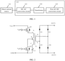
- FIG. 1 is a schematic diagram of a structure of a power supply according to an embodiment of this application.
- the power supply includes a direct current source 101 and a power converter 102.
- the direct current source 101 is configured to supply power to the power converter 102.
- the power converter 102 includes a DC-AC conversion circuit 103, a transformer 104, and a first AC-DC conversion circuit 105.
- the DC-AC conversion circuit 103 is configured to generate at least two different excitation voltages in a time-division manner.
- the DC-AC conversion circuit 103 is coupled to the first AC-DC conversion circuit 105 through the transformer 104.
- An output end of the first AC-DC conversion circuit 105 is used as an output end of the power converter 102, and may be connected to another circuit or load to supply power to the another circuit or load.
- the direct current source 101 is configured to supply power to the DC-AC conversion circuit 103.
- the transformer 104 includes a primary-side winding and a secondary-side winding.
- the power converter 102 further includes a capacitor.
- the capacitor is connected in series with the transformer 104.
- the capacitor may be directly connected in series with the transformer 104.
- the capacitor may be connected in series with the transformer 104 through another device.
- the capacitor may be connected in series on a primary-side winding side of the transformer 104, or connected in series on a secondary-side winding side of the transformer 104.
- the capacitor connected in series with the transformer 104 is disposed to avoid bias excitation caused by the at least two different excitation voltages.
- the capacitor may be referred to as a bias correction capacitor.
- the bias correction capacitor when the bias correction capacitor is connected in series on the primary-side winding side of the transformer 104, the DC-AC conversion circuit 103 is coupled to the transformer 104 through the bias correction capacitor.
- the transformer 104 is coupled to the first AC-DC conversion circuit through the bias correction capacitor.
- excitation is correspondingly performed on windings having different quantities of turns in the primary-side winding in a matched manner based on different excitation voltages generated by the DC-AC conversion circuit 103, to adjust currents and energy magnitudes of different excitation voltages input to the transformer. Therefore, voltage regulation flexibility of the power converter 102 can be improved.
- the DC-AC conversion circuit 103 includes at least three output connection ends.
- the primary-side winding of the transformer 104 includes at least two sub primary-side windings.
- the at least two sub primary-side windings include at least three primary-side winding connection ends.
- the at least two sub primary-side windings share one primary-side winding connection end.
- the at least three primary-side winding connection ends are configured to divide the primary-side winding into the at least two sub primary-side windings.
- the sub primary-side windings are the entire or a part of the primary-side winding.
- One excitation voltage of the DC-AC conversion circuit 103 is correspondingly output to one sub primary-side winding.
- a quantity of turns of the sub primary-side winding is correspondingly adjusted based on a change of the corresponding input excitation voltage.
- the at least three output connection ends of the DC-AC conversion circuit 103 are connected to the at least three primary-side winding connection ends in a one-to-one correspondence manner.
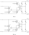
- FIG. 2 is a schematic diagram of a structure of a power converter according to an embodiment of this application.
- the DC-AC conversion circuit 103 includes a first switch Q1 and a second switch Q2.
- a primary-side winding of a transformer T1 has three primary-side winding connection ends A, B, and C.
- a winding between the primary-side winding connection end A and the primary-side winding connection end C is used as a first sub primary-side winding of at least two sub primary-side windings.
- a winding between the primary-side winding connection end B and the primary-side winding connection end C is used as a second sub primary-side winding of the at least two sub primary-side windings.
- a common connection end of the first sub primary-side winding and the second sub primary-side winding is the primary-side winding connection end C.
- One end of the first switch Q1 is connected to a first direct current source Vin1, and the other end of the first switch Q1 is connected to the primary-side winding connection end A.
- One end of the second switch Q2 is connected to the primary-side winding connection end B, and the other end of the second switch Q2 is grounded.
- the primary-side winding connection end C is grounded through a bias correction capacitor C1.
- the first direct current source Vin1 inputs a first excitation voltage to the transformer T1 after undergoing voltage division through the first switch Q1.
- a current of the first direct current source Vin1 passes through the first switch Q1 and the entire primary-side winding (that is, from the primary-side winding connection end A to the primary-side winding connection end C) and then flows into the bias correction capacitor C1. In this case, the bias correction capacitor C1 is charged.
- the bias correction capacitor C1 starts to discharge to generate a second excitation voltage.
- a discharge current passes through the primary-side winding connection end C, the primary-side winding connection end B, and the second switch Q2 and then flows back to the bias correction capacitor C1.
- the first direct current source Vin1 and the bias correction capacitor C1 (which is understood as an energy storage capacitor) are used as different power supplies, and two different excitation voltages are provided after voltage division.
- FIG. 2 shows only one winding tap (namely, the primary-side winding connection end B), a quantity of winding taps may also be increased.
- a new tap is added between the primary-side winding connection end A and the primary-side winding connection end B as a primary-side winding connection end D.
- a winding between the primary-side winding connection end D and the primary-side winding connection end C may be used as the first sub primary-side winding according to an actual requirement, and a winding between the primary-side winding connection end B and the primary-side winding connection end C is used as the second sub primary-side winding.
- the primary-side winding connection end C is used as a common connection end of the first sub primary-side winding and the second sub primary-side winding.
- a new tap is added between the primary-side winding connection end B and the primary-side winding connection end C as a primary-side winding connection end D.
- a winding between the primary-side winding connection end A and the primary-side winding connection end D may be used as the first sub primary-side winding according to an actual requirement, and a winding between the primary-side winding connection end B and the primary-side winding connection end D is used as the second sub primary-side winding.
- the primary-side winding connection end D is used as a common connection end of the first sub primary-side winding and the second sub primary-side winding.
- the first AC-DC conversion circuit 105 includes a first rectifying device D1, a second rectifying device D2, a third rectifying device D3, and a fourth rectifying device D4, and implements rectification by using the first rectifying device D1 to the fourth rectifying device D4, that is, converts an alternating current into a direct current.
- the first rectifying device D1 and the third rectifying device D3 are connected in series and then connected in parallel to output ends OUT1 and OUT2 of the first AC-DC conversion circuit 105.
- the second rectifying device D2 and the fourth rectifying device D4 are connected in series and then connected in parallel to the output ends OUT1 and OUT2 of the first AC-DC conversion circuit 105.
- a secondary-side winding connection end D and a secondary-side winding connection end E of the transformer T1 are connected in parallel between a series connection end of the first rectifying device D1 and the third rectifying device D3 and a series connection end of the second rectifying device D2 and the fourth rectifying device D4.
- the first rectifying device to the fourth rectifying device are disposed, to implement rectification on currents that are output by the transformer and that have different current flow directions.
- At least one of the first rectifying device, the second rectifying device, the third rectifying device, and the fourth rectifying device may be implemented by using at least one of a diode, a switching transistor, or the like.
- the switching transistor includes at least one of a transistor, a metal-oxide-semiconductor field-effect transistor (Metal-Oxide-Semiconductor Field-Effect Transistor, MOSFET, MOS for short), or the like.
- the transistor includes a PNP transistor and an NPN transistor.
- the MOS transistor includes an NMOS transistor and a PMOS transistor.
- the first rectifying device to the fourth rectifying device in FIG. 2 are implemented by using diodes.
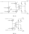
- FIG. 3 is a schematic diagram of a structure of another power converter according to an embodiment of this application.
- the DC-AC conversion circuit 103 includes a first switch Q1, a second switch Q2, a third switch Q3, and a fourth switch Q4.
- a primary-side winding of a transformer T1 in FIG. 3 has three primary-side winding connection ends A, B, and C.
- a winding between the primary-side winding connection end A and the primary-side winding connection end C is used as a first sub primary-side winding of at least two sub primary-side windings
- a winding between the primary-side winding connection end B and the primary-side winding connection end C is used as a second sub primary-side winding of the at least two sub primary-side windings.
- a common connection end of the first sub primary-side winding and the second sub primary-side winding is the primary-side winding connection end C.
- the first switch Q1 and the third switch Q3 are connected in series and then connected to a second direct current source Vin2.
- One end of the second switch Q2 is connected to a first direct current source Vin1, and the other end of the second switch Q2 is used as an output connection end of the DC-AC conversion circuit 103 and is connected to the primary-side winding connection end A of the first sub primary-side winding.
- One end of the fourth switch Q4 is connected to the primary-side winding connection end B of the second sub primary-side winding, and the other end of the fourth switch Q4 is grounded.
- the primary-side winding connection end C is connected to a series connection end of the first switch Q1 and the third switch Q3 through a bias correction capacitor C1.
- the first direct current source Vin1 inputs a first excitation voltage to the transformer T1 after undergoing voltage division through the second switch Q2.
- a current of the first direct current source Vin1 passes through the second switch Q2 and the entire primary-side winding (that is, from the primary-side winding connection end A to the primary-side winding connection end C), flows into the bias correction capacitor C1, and then flows into a ground cable after passing through the third switch Q3.
- the second direct current source Vin2 inputs a second excitation voltage to the transformer T1 after undergoing voltage division through the first switch Q1 and the bias correction capacitor C1.
- a current of the second direct current source Vin2 passes through the first switch Q1, the bias correction capacitor C1, the primary-side winding connection end C, the primary-side winding connection end B, and the fourth switch Q4 and then flows into the ground cable.
- the first switch to the fourth switch are disposed to implement that the first direct current source Vin1 and the second direct current source Vin2 are used as different power supplies in a time-division manner.
- the different power supplies may provide two different excitation voltages after voltage division.
- the first AC-DC conversion circuit 105 in FIG. 3 has a same structure as the first AC-DC conversion circuit shown in FIG. 2 . Details are not described again.
- At least one of the first switch, the second switch, the third switch, and the fourth switch may be implemented by using at least one of a manual switch, a relay, a switching transistor, and the like.
- the switching transistor includes at least one of a transistor, an MOS transistor, or the like.
- the transistor includes a PNP transistor and an NPN transistor.
- the MOS transistor includes an NMOS transistor and a PMOS transistor.
- the switches in FIG. 2 and FIG. 3 are implemented by using NMOS transistors, where VgM, VgH, VgS, and VgL are base control signals of respective corresponding NMOS transistors.
- FIG. 4a is a schematic diagram of a structure of another power converter according to an embodiment of this application.
- the DC-AC conversion circuit 103 includes a first switch Q1, a second switch Q2, a third switch Q3, and a fourth switch Q4.
- a primary-side winding of a transformer T1 in FIG. 4a has three primary-side winding connection ends A, B, and C.
- a winding between the primary-side winding connection end A and the primary-side winding connection end C is used as a first sub primary-side winding of at least two sub primary-side windings
- a winding between the primary-side winding connection end B and the primary-side winding connection end C is used as a second sub primary-side winding of the at least two sub primary-side windings.
- a common connection end of the first sub primary-side winding and the second sub primary-side winding is the primary-side winding connection end C.
- the first switch Q1 and the third switch Q3 are connected in series and then connected to a first direct current source Vin1.
- One end of the second switch Q2 is connected to a first direct current source Vin1, and the other end of the second switch Q2 is used as an output connection end of the DC-AC conversion circuit 103 and is connected to the primary-side winding connection end A of the first sub primary-side winding.
- One end of the fourth switch Q4 is connected to the primary-side winding connection end B of the second sub primary-side winding, and the other end of the fourth switch Q4 is grounded.
- the primary-side winding connection end C is connected to a series connection end of the first switch Q1 and the third switch Q3 through a bias correction capacitor.
- a duty cycle of the first switch Q1 and the fourth switch Q4 is different from a duty cycle of the second switch Q2 and the third switch Q3. This may be understood as that in a working time sequence, front and back duty cycles are asymmetric.
- the duty cycle of the first switch Q1 and the fourth switch Q4 means first time when the first switch Q1 and the fourth switch Q4 are simultaneously turned on.
- the duty cycle of the second switch Q2 and the third switch Q3 means first time when the second switch Q2 and the third switch Q3 are simultaneously turned on. That the duty cycles are different means that the first switch Q1 to the fourth switch Q4 are not simultaneously turned on, and the first time is different from the first time.
- a time length of the first time is greater than a time length of the second time.
- a time length of the second time is greater than a time length of the first time. This may be set according to an actual requirement.
- Working logic of the DC-AC conversion circuit 103 shown in FIG. 4a is similar to working logic of the DC-AC conversion circuit 103 shown in FIG. 3 .
- the first direct current source Vin1 inputs a first excitation voltage to the transformer T1 after undergoing voltage division through the second switch Q2.
- a current of the first direct current source Vin1 passes through the second switch Q2 and the entire primary-side winding (that is, from the primary-side winding connection end A to the primary-side winding connection end C), flows into the bias correction capacitor C1, and then flows into a ground cable after passing through the third switch Q3.
- the first direct current source Vin1 inputs a second excitation voltage to the transformer T1 after undergoing voltage division through the first switch Q1 and the bias correction capacitor C1.
- a current of the first direct current source Vin1 passes through the first switch Q1, the bias correction capacitor C1, the primary-side winding connection end C, the primary-side winding connection end B, and the fourth switch Q4 and then flows into the ground cable.
- the first direct current source Vin1 is used as a power supply, the duty cycles of the first switch to the fourth switch are controlled to be different, and two different excitation voltages are provided after voltage division.
- the first AC-DC conversion circuit 105 in FIG. 4a has a same structure as the first AC-DC conversion circuit shown in FIG. 2 . Details are not described again.
- FIG. 4b is a schematic diagram of a structure of another power converter according to an embodiment of this application.
- One end of the second switch Q2 is connected to the first direct current source Vin1, and the other end of the second switch Q2 is connected to the primary-side winding connection end B.
- One end of the fourth switch Q4 is connected to the primary-side winding connection end A, and the other end of the fourth switch Q4 is grounded.
- the primary-side winding connection end C is used as a common connection end and connected to a series connection end of the first switch Q1 and the third switch Q3.
- the secondary-side winding of the transformer 104 includes at least two sub secondary-side windings.
- the at least two sub secondary-side windings include at least three secondary-side winding connection ends.
- the at least two sub secondary-side windings share one secondary-side winding connection end.
- the at least three secondary-side winding connection ends are configured to divide the secondary-side winding into at least two sub secondary-side windings.
- a quantity of turns of one sub secondary-side winding is correspondingly adjusted based on a change of an excitation voltage input to the primary-side winding of the transformer.
- the sub secondary-side windings are the entire or a part of the secondary-side winding.
- the first AC-DC conversion circuit includes at least three input connection ends.
- the at least three input connection ends are connected to the at least three secondary-side winding connection ends in a one-to-one correspondence manner.
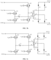
- FIG. 5a is a schematic diagram of a structure of another power converter according to an embodiment of this application.
- the first AC-DC conversion circuit 105 includes a first rectifying device D1, a second rectifying device D2, a third rectifying device D3, and a fourth rectifying device D4.
- a secondary-side winding of a transformer T1 has three secondary-side winding connection ends C, D, and E.
- a winding between the secondary-side winding connection end C and the secondary-side winding connection end E is used as a first sub secondary-side winding of at least two sub secondary-side windings
- a winding between the secondary-side winding connection end D and the secondary-side winding connection end E is used as a second sub secondary-side winding of the at least two sub secondary-side windings.
- a common connection end of the first sub secondary-side winding and the second sub secondary-side winding is the secondary-side winding connection end E.
- the first rectifying device D1 and the third rectifying device D3 are connected in series and then connected in parallel to output ends OUT1 and OUT2 of the first AC-DC conversion circuit 105.
- One end of the second rectifying device D2 is connected to the secondary-side winding connection end C of the first sub secondary-side winding, and the other end of the second rectifying device D2 is connected to the output end OUT1 of the first AC-DC conversion circuit 105.
- One end of the fourth rectifying device D4 is connected to the secondary-side winding connection end D of the second sub secondary-side winding, and the other end of the fourth rectifying device D4 is connected to the output end OUT2 of the first AC-DC conversion circuit 105.
- the secondary-side winding connection end E is connected to a series connection end of the first rectifying device D1 and the third rectifying device D3.
- the DC-AC conversion circuit 103 in FIG. 5a includes a first switch Q1 and a second switch Q2.
- the first switch Q1 and the second switch Q2 are connected in series and then connected in parallel to a first direct current source Vin1.
- a primary-side winding connection end A of the transformer T1 is connected to a series connection end of the first switch Q1 and the second switch Q2, and a primary-side winding connection end B is grounded through a bias correction capacitor C1.
- the first direct current source Vin1 inputs a first excitation voltage to the transformer T1 after undergoing voltage division through the first switch Q1.
- a current of the first direct current source Vin1 passes through the first switch Q1 and a primary-side winding and then flows into the bias correction capacitor C1.
- the bias correction capacitor C1 is charged.
- voltage transformation is performed through the first sub secondary-side winding, and rectification is performed through the second rectifying device D2 and the third rectifying device D3.
- the current passes through the primary-side winding and the second switch Q2 and then flows back to the bias correction capacitor C1.
- voltage transformation is performed through the second sub secondary-side winding, and rectification is performed through the first rectifying device D1 and the fourth rectifying device D4.
- different excitation voltages input by the primary-side winding may be matched, and voltage transformation is performed by using sub secondary-side windings having different quantities of turns, thereby effectively improving voltage adjustment flexibility of the power converter.
- FIG. 5b is a schematic diagram of a structure of another power converter according to an embodiment of this application.
- the DC-AC conversion circuit 103 includes a first switch Q1, a second switch Q2, a third switch Q3, and a fourth switch Q4.
- the first switch Q1 and the third switch Q3 are connected in series and then connected to a second direct current source Vin2.
- the second switch Q2 and the fourth switch Q4 are connected in series and then connected to a first direct current source Vin1.
- a primary-side winding connection end A is connected to a series connection end of the second switch Q2 and the fourth switch Q4.
- a primary-side winding connection end B is connected to a series connection end of the first switch Q1 and the third switch Q3 through a bias correction capacitor C1.
- the first direct current source Vin1 inputs a first excitation voltage to a transformer T1 after undergoing voltage division through the second switch Q2.
- a current of the first direct current source Vin1 passes through the second switch Q2 and a primary-side winding, flows into the bias correction capacitor C1, and then flows into a ground cable after passing through the third switch Q3.
- voltage transformation is performed through a first sub secondary-side winding, and rectification is performed through a second rectifying device D2 and a third rectifying device D3.
- the second direct current source Vin2 inputs a second excitation voltage to the transformer T1 after undergoing voltage division through the first switch Q1 and the bias correction capacitor C1.
- a current of the second direct current source Vin2 passes through the first switch Q1, the bias correction capacitor C1, the primary-side winding, and the fourth switch Q4 and then flows into the ground cable.
- voltage transformation is performed through a second sub secondary-side winding, and rectification is performed through a first rectifying device D1 and a fourth rectifying device D4.
- FIG. 5c is a schematic diagram of a structure of another power converter according to an embodiment of this application.
- the DC-AC conversion circuit 103 includes a first switch Q1, a second switch Q2, a third switch Q3, and a fourth switch Q4.
- the first switch Q1 and the third switch Q3 are connected in series and then connected to a first direct current source Vin1.
- the second switch Q2 and the fourth switch Q4 are connected in series and then connected to the first direct current source Vin1.
- a primary-side winding connection end A is connected to a series connection end of the second switch Q2 and the fourth switch Q4.
- a primary-side winding connection end B is connected to a series connection end of the first switch Q1 and the third switch Q3 through a bias correction capacitor C1.
- a duty cycle of the first switch Q1 and the fourth switch Q4 is different from a duty cycle of the second switch Q2 and the third switch Q3, to output two different excitation voltages.
- the first direct current source Vin1 inputs a first excitation voltage to a transformer T1 after undergoing voltage division through the second switch Q2.
- a current of the first direct current source Vin1 passes through the second switch Q2 and a primary-side winding, flows into the bias correction capacitor C1, and then flows into a ground cable after passing through the third switch Q3.
- voltage transformation is performed through a first sub secondary-side winding, and rectification is performed through a second rectifying device D2 and a third rectifying device D3.
- the first direct current source Vin1 inputs a second excitation voltage to the transformer T1 after undergoing voltage division through the first switch Q1 and the bias correction capacitor C1.
- a current of the first direct current source Vin1 passes through the first switch Q1, the bias correction capacitor C1, the primary-side winding, and the fourth switch Q4 and then flows into the ground cable.
- voltage transformation is performed through a second sub secondary-side winding, and rectification is performed through a first rectifying device D1 and a fourth rectifying device D4.
- both a quantity of turns of the primary-side winding and a quantity of turns of a secondary-side winding that play a role of voltage transformation may be adjusted at the same time, to adjust currents and energy magnitudes of different excitation voltages input to the transformer. Therefore, voltage adjustment flexibility of the power converter 102 can be improved.
- the primary-side winding of the transformer 104 includes at least two sub primary-side windings.
- the at least two sub primary-side windings include at least three primary-side winding connection ends.
- the at least two sub primary-side windings share one primary-side winding connection end.
- the at least three primary-side winding connection ends are configured to divide the primary-side winding into the at least two sub primary-side windings.
- One excitation voltage of the DC-AC conversion circuit 103 is correspondingly output to one sub primary-side winding.
- the DC-AC conversion circuit 103 includes at least three output connection ends.
- the at least three output connection ends are connected to the at least three primary-side winding connection ends in a one-to-one correspondence manner.
- the secondary-side winding of the power transformer includes at least two sub secondary-side windings.
- the at least two sub secondary-side windings include at least three secondary-side winding connection ends.
- the at least two sub secondary-side windings share one secondary-side winding connection end.
- the at least three secondary-side winding connection ends are configured to divide the secondary-side winding into at least two sub secondary-side windings.
- the at least two sub secondary-side windings are in a one-to-one correspondence with the at least two sub primary-side windings.
- a quantity of turns of each sub primary-side winding and a quantity of turns of the corresponding sub secondary-side winding are correspondingly adjusted based on a change of an excitation voltage input to the corresponding sub primary-side winding.
- the first AC-DC conversion circuit includes at least three input connection ends.
- the at least three input connection ends are connected to the at least three secondary-side winding connection ends in a one-to-one correspondence manner.
- FIG. 6 is a schematic diagram of a structure of another power converter according to an embodiment of this application.
- the DC-AC conversion circuit 103 includes a first switch Q1, a second switch Q2, a third switch Q3, and a fourth switch Q4.
- a primary-side winding of a transformer T1 has three primary-side winding connection ends A, B, and C.
- a winding between the primary-side winding connection end A and the primary-side winding connection end C is used as a first sub primary-side winding of at least two sub primary-side windings.
- a winding between the primary-side winding connection end B and the primary-side winding connection end C is used as a second sub primary-side winding of the at least two sub primary-side windings.
- a common connection end of the first sub primary-side winding and the second sub primary-side winding is the primary-side winding connection end C.
- the first switch Q1 and the third switch Q3 are connected in series and then connected to a second direct current source Vin2.
- One end of the second switch Q2 is connected to a first direct current source Vin1, and the other end of the second switch Q2 is used as an output connection end of the DC-AC conversion circuit 103 and is connected to the primary-side winding connection end A of the first sub primary-side winding.
- the fourth switch Q4 is connected to the primary-side winding connection end B of the second sub primary-side winding, and the other end of the fourth switch Q4 is grounded.
- the primary-side winding connection end C is connected to a series connection end of the first switch Q1 and the third switch Q3 through a bias correction capacitor C1.
- a secondary-side winding of the transformer T1 has three secondary-side winding connection ends D, E, and F.
- a winding between the secondary-side winding connection end D and the secondary-side winding connection end F is used as a first sub secondary-side winding of at least two sub secondary-side windings.
- a winding between the secondary-side winding connection end E and the secondary-side winding connection end F is used as a second sub secondary-side winding of the at least two sub secondary-side windings.
- a common connection end of the first sub secondary-side winding and the second sub secondary-side winding is the secondary-side winding connection end F.
- the first rectifying device D1 and the third rectifying device D3 are connected in series and then connected in parallel to output ends OUT1 and OUT2 of the first AC-DC conversion circuit 105.
- One end of a second rectifying device D2 is connected to the secondary-side winding connection end D of the first sub secondary-side winding, and the other end of the second rectifying device D2 is connected to the output end OUT1 of the first AC-DC conversion circuit 105.
- One end of a fourth rectifying device D4 is connected to the secondary-side winding connection end E of the second sub secondary-side winding, and the other end of the fourth rectifying device D4 is connected to the output end OUT2 of the first AC-DC conversion circuit 105.
- the secondary-side winding connection end F is connected to a series connection end of the first rectifying device D1 and the third rectifying device D3.
- the power converter further includes an inductor connected in series with the transformer.
- a quantity of capacitors and/or inductors connected in series with the transformer is not particularly limited, and may be set according to an actual requirement.
- FIG. 7 is a schematic diagram of a structure of another power converter according to an embodiment of this application.
- a bias correction capacitor C1 is connected in series with an inductor L1.
- a DC-AC conversion circuit is coupled to a transformer T1 through the bias correction capacitor C1 and the inductor L1.
- the DC-AC conversion circuit includes a first switch Q1, a second switch Q2, a third switch Q3, and a fourth switch Q4.
- the bias correction capacitor C1 and the inductor L1 are disposed to reduce a switching loss of a switching device (for example, at least one switch in the first switch to the fourth switch) in the DC-AC conversion circuit, thereby helping reduce a loss of the DC-AC conversion circuit, and implementing voltage stability.
- a switching device for example, at least one switch in the first switch to the fourth switch
- FIG. 7 A capacitor C2 and an inductor L2 are connected in series.
- the transformer T1 is coupled to a first AC-DC conversion circuit through the capacitor C2 and the inductor L2.
- the first AC-DC conversion circuit includes a first rectifying device D1, a second rectifying device D2, a third rectifying device D3, and a fourth rectifying device D4.
- the capacitor C2 and the inductor L2 are disposed to adjust an output voltage of the first AC-DC conversion circuit, and the output voltage can be stabilized.
- the power converter further includes an output capacitor connected in parallel with the first AC-DC conversion circuit.
- the output capacitor is disposed to stabilize the output voltage of the first AC-DC conversion circuit.
- the first AC-DC conversion circuit includes a first rectifying device D1, a second rectifying device D2, a third rectifying device D3, and a fourth rectifying device D4.
- the first AC-DC conversion circuit is connected in parallel with an output capacitor C3 to stabilize an output voltage of the first AC-DC conversion circuit.
- the direct current source includes a DC-DC conversion circuit.
- the DC-DC conversion circuit includes at least one of the following: a Boost circuit, a Buck circuit, a Buck-Boost circuit of a positive output type, a single ended primary inductor converter (Single Ended Primary Inductor Converter, SEPIC) circuit, and a dual-SEPIC circuit.
- SEPIC Single Ended Primary Inductor Converter
- the Boost circuit is a switching direct current boost circuit, and can enable an output voltage to be higher than an input voltage.
- the Buck circuit is a buck chopper with an output voltage being lower than an input voltage.
- An output voltage of the Buck-Boost circuit may be lower than or higher than an input voltage. However, a polarity of the output voltage is opposite to that of the input voltage.
- the SEPIC circuit is a DC-DC circuit that allows an output voltage to be greater than, less than, or equal to an input voltage.
- the output voltage of the SEPIC circuit is controlled by a duty cycle of a switch (such as a transistor or an MOS transistor). In the SEPIC circuit, both a power supply current and a load current are continuous, thereby facilitating input filtering and output filtering.
- the dual-SEPIC circuit is also referred to as a Zeta circuit.
- the Zeta circuit is a DC-DC circuit that allows an output voltage to be greater than, less than, or equal to an input voltage. Both an input current and an output current of the Zeta circuit are discontinuous.
- the first direct current source Vin1 may be implemented by using any one of the following: a Boost circuit, a Buck circuit, a Buck-Boost circuit of a positive output type, an SEPIC circuit, and a dual-SEPIC circuit.
- the first direct current source Vin1 may be implemented by using any one of the following: a Boost circuit, a Buck circuit, a Buck-Boost circuit of a positive output type, an SEPIC circuit, and a dual-SEPIC circuit; and the second direct current source Vin2 may be implemented by using any one of the following: a Boost circuit, a Buck circuit, a Buck-Boost circuit of a positive output type, an SEPIC circuit, a dual-SEPIC circuit.
- FIG. 8 is a schematic diagram of a structure of a power supply according to an embodiment of this application.
- a Boost circuit is used as the second direct current source Vin2.
- the Boost circuit is implemented by using a fifth switching transistor Q5, a sixth switching transistor Q6, an inductor L1, and a capacitor C2.
- An example in which the fifth switching transistor Q5 and the sixth switching transistor Q6 are implemented by using NMOS transistors is used.
- VgN and VgP are base control signals of the NMOS transistors corresponding to the fifth switching transistor Q5 and the sixth switching transistor Q6.
- a direct current source Vin is directly used as the first direct current source Vin1, and provides the first excitation voltage to the transformer T1 after undergoing voltage division through the second switch Q2.
- the Boost circuit is used as the second direct current source Vin2. After being processed by the Boost circuit, the direct current source Vin provides the second excitation voltage to the transformer T1 after undergoing voltage division through the first switch Q1 and the bias correction capacitor C1.
- the direct current source includes an alternating current source and a second AC-DC conversion circuit.
- the second AC-DC conversion circuit is configured to convert an alternating current provided by the alternating current source into a direct current, to supply power to the DC-AC conversion circuit.
- a specific circuit structure of the second AC-DC conversion circuit is not particularly limited, provided that AC-DC conversion can be implemented.
Landscapes
- Engineering & Computer Science (AREA)
- Power Engineering (AREA)
- Physics & Mathematics (AREA)
- Electromagnetism (AREA)
- Rectifiers (AREA)
Applications Claiming Priority (1)
| Application Number | Priority Date | Filing Date | Title |
|---|---|---|---|
| PCT/CN2022/114925 WO2024040537A1 (zh) | 2022-08-25 | 2022-08-25 | 功率变换器及电源 |
Publications (2)
| Publication Number | Publication Date |
|---|---|
| EP4564658A1 true EP4564658A1 (de) | 2025-06-04 |
| EP4564658A4 EP4564658A4 (de) | 2025-10-01 |
Family
ID=89363608
Family Applications (1)
| Application Number | Title | Priority Date | Filing Date |
|---|---|---|---|
| EP22956083.4A Pending EP4564658A4 (de) | 2022-08-25 | 2022-08-25 | Stromwandler und stromquelle |
Country Status (4)
| Country | Link |
|---|---|
| US (1) | US20250192664A1 (de) |
| EP (1) | EP4564658A4 (de) |
| CN (1) | CN117356023A (de) |
| WO (1) | WO2024040537A1 (de) |
Families Citing this family (2)
| Publication number | Priority date | Publication date | Assignee | Title |
|---|---|---|---|---|
| CN119254033B (zh) * | 2024-12-05 | 2025-06-06 | 西安图为电气技术有限公司 | 一种等效全桥整流电路 |
| CN119995387A (zh) * | 2025-04-16 | 2025-05-13 | 比亚迪股份有限公司 | 供电控制装置、励磁控制方法、动力系统及车辆 |
Family Cites Families (10)
| Publication number | Priority date | Publication date | Assignee | Title |
|---|---|---|---|---|
| US7729135B1 (en) * | 2007-05-10 | 2010-06-01 | Fairchild Semiconductor Corporation | Power converter using a single tapped transformer for multiple ranges of input voltage |
| US8106636B2 (en) * | 2008-02-22 | 2012-01-31 | Murata Power Solutions | Method and apparatus for power conversion with wide input voltage range |
| TWI479792B (zh) * | 2012-04-23 | 2015-04-01 | Delta Electronics Inc | 電源轉換器及其切換控制方法 |
| CN103378735A (zh) * | 2012-04-23 | 2013-10-30 | 台达电子工业股份有限公司 | 电源转换器及其切换控制方法 |
| CN107231090A (zh) * | 2016-03-23 | 2017-10-03 | 施耐德电气工业公司 | 开关式电源 |
| CN105915066A (zh) * | 2016-07-01 | 2016-08-31 | 洛阳嘉盛电源科技有限公司 | 一种功率变换电路 |
| CN109004675B (zh) * | 2018-08-27 | 2021-12-03 | 湖北工业大学 | 一种自适应切换绕组的宽输入辅助电源 |
| CN109980942A (zh) * | 2019-03-25 | 2019-07-05 | 华中科技大学 | 一种基于分段式变压器的dc-dc变换器 |
| CN109889051A (zh) * | 2019-04-04 | 2019-06-14 | 深圳市三旺通信股份有限公司 | 一种dcdc隔离电源电路 |
| CN114070083B (zh) * | 2021-10-13 | 2025-08-01 | 华为技术有限公司 | Dc/dc变换器及其输出电压控制方法 |
-
2022
- 2022-08-25 CN CN202280035700.7A patent/CN117356023A/zh active Pending
- 2022-08-25 WO PCT/CN2022/114925 patent/WO2024040537A1/zh not_active Ceased
- 2022-08-25 EP EP22956083.4A patent/EP4564658A4/de active Pending
-
2025
- 2025-02-20 US US19/058,255 patent/US20250192664A1/en active Pending
Also Published As
| Publication number | Publication date |
|---|---|
| US20250192664A1 (en) | 2025-06-12 |
| CN117356023A (zh) | 2024-01-05 |
| EP4564658A4 (de) | 2025-10-01 |
| WO2024040537A1 (zh) | 2024-02-29 |
Similar Documents
| Publication | Publication Date | Title |
|---|---|---|
| US20250192664A1 (en) | Power converter and power supply | |
| US8767415B2 (en) | High efficiency and fast response AC-DC voltage converters | |
| US7239530B1 (en) | Apparatus for isolated switching power supply with coupled output inductors | |
| US8233298B2 (en) | Power factor correction rectifier that operates efficiently over a range of input voltage conditions | |
| US8068355B1 (en) | Apparatus for isolated switching power supply with coupled output inductors | |
| US5057990A (en) | Bidirectional switching power apparatus with AC or DC output | |
| US20120286678A1 (en) | Drive circuit for realizing accurate constant current of multiple leds | |
| CN111193400B (zh) | 电源装置 | |
| JP2011160521A (ja) | スイッチング電源装置 | |
| US8300437B2 (en) | Multi-output DC-to-DC conversion apparatus with voltage-stabilizing function | |
| US8064228B2 (en) | Power supply apparatus with current-sharing function | |
| US20140071716A1 (en) | High efficient single switch single stage power factor correction power supply | |
| EP2441161B1 (de) | Duales antriebssystem für trafoisolierte halbbrücken- und vollbrücken-durchflusswandler | |
| US20170264205A1 (en) | Bidirectional isolated multi-level dc-dc converter and method thereof | |
| WO2004036726A1 (ja) | 直流変換装置 | |
| US6504735B2 (en) | Regulated voltage reducing high-voltage isolated DC/DC converter system | |
| US7816895B2 (en) | Power supplying device | |
| JP2016086562A (ja) | 電源回路 | |
| US7079403B2 (en) | Isolated DC-DC converters | |
| US20080074090A1 (en) | Tapped converter | |
| US10164533B2 (en) | Converter circuit for reducing a nominal capacitor voltage | |
| KR102537358B1 (ko) | 절연형 스위칭 전원 | |
| KR20240171491A (ko) | 전력 전달 장치 | |
| TWI597928B (zh) | 降壓型潘恭直流轉換器 | |
| JP2007267450A (ja) | 多出力電源装置 |
Legal Events
| Date | Code | Title | Description |
|---|---|---|---|
| STAA | Information on the status of an ep patent application or granted ep patent |
Free format text: STATUS: THE INTERNATIONAL PUBLICATION HAS BEEN MADE |
|
| PUAI | Public reference made under article 153(3) epc to a published international application that has entered the european phase |
Free format text: ORIGINAL CODE: 0009012 |
|
| STAA | Information on the status of an ep patent application or granted ep patent |
Free format text: STATUS: REQUEST FOR EXAMINATION WAS MADE |
|
| 17P | Request for examination filed |
Effective date: 20250227 |
|
| AK | Designated contracting states |
Kind code of ref document: A1 Designated state(s): AL AT BE BG CH CY CZ DE DK EE ES FI FR GB GR HR HU IE IS IT LI LT LU LV MC MK MT NL NO PL PT RO RS SE SI SK SM TR |
|
| A4 | Supplementary search report drawn up and despatched |
Effective date: 20250828 |
|
| RIC1 | Information provided on ipc code assigned before grant |
Ipc: H02M 3/335 20060101AFI20250822BHEP Ipc: H02M 1/10 20060101ALI20250822BHEP Ipc: H02M 1/00 20060101ALI20250822BHEP |
|
| DAV | Request for validation of the european patent (deleted) | ||
| DAX | Request for extension of the european patent (deleted) |