EP4563711A1 - Method for denitrifying melted steel - Google Patents
Method for denitrifying melted steel Download PDFInfo
- Publication number
- EP4563711A1 EP4563711A1 EP23854752.5A EP23854752A EP4563711A1 EP 4563711 A1 EP4563711 A1 EP 4563711A1 EP 23854752 A EP23854752 A EP 23854752A EP 4563711 A1 EP4563711 A1 EP 4563711A1
- Authority
- EP
- European Patent Office
- Prior art keywords
- oxygen
- carbon
- molten steel
- point
- source
- Prior art date
- Legal status (The legal status is an assumption and is not a legal conclusion. Google has not performed a legal analysis and makes no representation as to the accuracy of the status listed.)
- Pending
Links
Images


Classifications
-
- C—CHEMISTRY; METALLURGY
- C21—METALLURGY OF IRON
- C21C—PROCESSING OF PIG-IRON, e.g. REFINING, MANUFACTURE OF WROUGHT-IRON OR STEEL; TREATMENT IN MOLTEN STATE OF FERROUS ALLOYS
- C21C7/00—Treating molten ferrous alloys, e.g. steel, not covered by groups C21C1/00 - C21C5/00
- C21C7/04—Removing impurities by adding a treating agent
-
- C—CHEMISTRY; METALLURGY
- C21—METALLURGY OF IRON
- C21C—PROCESSING OF PIG-IRON, e.g. REFINING, MANUFACTURE OF WROUGHT-IRON OR STEEL; TREATMENT IN MOLTEN STATE OF FERROUS ALLOYS
- C21C5/00—Manufacture of carbon-steel, e.g. plain mild steel, medium carbon steel or cast steel or stainless steel
- C21C5/52—Manufacture of steel in electric furnaces
- C21C5/5211—Manufacture of steel in electric furnaces in an alternating current [AC] electric arc furnace
- C21C5/5217—Manufacture of steel in electric furnaces in an alternating current [AC] electric arc furnace equipped with burners or devices for injecting gas, i.e. oxygen, or pulverulent materials into the furnace
-
- C—CHEMISTRY; METALLURGY
- C21—METALLURGY OF IRON
- C21C—PROCESSING OF PIG-IRON, e.g. REFINING, MANUFACTURE OF WROUGHT-IRON OR STEEL; TREATMENT IN MOLTEN STATE OF FERROUS ALLOYS
- C21C7/00—Treating molten ferrous alloys, e.g. steel, not covered by groups C21C1/00 - C21C5/00
- C21C7/0025—Adding carbon material
-
- C—CHEMISTRY; METALLURGY
- C21—METALLURGY OF IRON
- C21C—PROCESSING OF PIG-IRON, e.g. REFINING, MANUFACTURE OF WROUGHT-IRON OR STEEL; TREATMENT IN MOLTEN STATE OF FERROUS ALLOYS
- C21C7/00—Treating molten ferrous alloys, e.g. steel, not covered by groups C21C1/00 - C21C5/00
- C21C7/0037—Treating molten ferrous alloys, e.g. steel, not covered by groups C21C1/00 - C21C5/00 by injecting powdered material
-
- C—CHEMISTRY; METALLURGY
- C21—METALLURGY OF IRON
- C21C—PROCESSING OF PIG-IRON, e.g. REFINING, MANUFACTURE OF WROUGHT-IRON OR STEEL; TREATMENT IN MOLTEN STATE OF FERROUS ALLOYS
- C21C7/00—Treating molten ferrous alloys, e.g. steel, not covered by groups C21C1/00 - C21C5/00
- C21C7/04—Removing impurities by adding a treating agent
- C21C7/072—Treatment with gases
-
- Y—GENERAL TAGGING OF NEW TECHNOLOGICAL DEVELOPMENTS; GENERAL TAGGING OF CROSS-SECTIONAL TECHNOLOGIES SPANNING OVER SEVERAL SECTIONS OF THE IPC; TECHNICAL SUBJECTS COVERED BY FORMER USPC CROSS-REFERENCE ART COLLECTIONS [XRACs] AND DIGESTS
- Y02—TECHNOLOGIES OR APPLICATIONS FOR MITIGATION OR ADAPTATION AGAINST CLIMATE CHANGE
- Y02P—CLIMATE CHANGE MITIGATION TECHNOLOGIES IN THE PRODUCTION OR PROCESSING OF GOODS
- Y02P10/00—Technologies related to metal processing
- Y02P10/20—Recycling
Definitions
- the present invention relates to a method for denitrifying molten steel by supplying an oxygen-containing gas and a carbon source thereto during a step of producing steel by processing an iron source raw material, such as scrap, reduced iron, and pig iron, in a melting furnace or a refining furnace.
- an iron source raw material such as scrap, reduced iron, and pig iron
- Nitrogen is a component detrimental to metallic materials.
- nitrogen [N] in molten iron is removed by being adsorbed onto the surfaces of bubbles of carbon monoxide (CO) that are mainly generated during the decarburization of molten pig iron. Since molten steel with a low carbon concentration generates a limited amount of carbon monoxide, it is impossible to reduce the nitrogen concentration in the molten steel to a low concentration using such a method.
- molten iron refers to molten metal mainly composed of iron, that is, molten metal in which the content of iron is over 50%. Examples of molten iron include molten pig iron, molten steel, a molten cold iron source, and molten metal having the mixture.
- Patent Literature 1 discloses limiting conditions, such as the carbon blowing rate and the oxygen supply rate to molten steel, and also limiting the nitrogen concentration ( ⁇ 3 vol.%) in a carrier gas for blowing carbon into the molten steel. Patent Literature 1 also discloses that promoting denitrification and suppressing nitrogen adsorption at the same time can reduce the nitrogen concentration [N] in the molten steel to 25 mass ppm or less at the termination of refining.
- Patent Literature 2 discloses that a hydrocarbon-containing gas is used as a carrier gas for blowing a carbon source into molten steel. Patent Literature 2 also discloses that it is possible to obtain the effects of promoting carburization and reducing the nitrogen concentration [N] in the molten steel to less than about 20 mass ppm compared to when air is used as the carrier gas.
- Patent Literature 3 discloses that carbon and oxygen are injected simultaneously but separately into the same zone within a furnace. Patent Literature 3 also discloses that the denitrification of molten steel improves by about 5 mass ppm compared to when oxygen is injected alone.
- Patent Literature 1 and Patent Literature 2 use an argon gas or a hydrocarbon-containing gas as a carrier gas. This requires a huge investment in facilities and equipment, such as a pipe for introducing the gas, which is different from ordinary gas, and a gas storage tank.
- the present invention has been made in view of the above circumstances and aims to propose a technology capable of stably reducing the nitrogen concentration in molten steel in a melting furnace or a refining furnace to a low nitrogen concentration range without requiring a huge investment.
- a method for denitrifying molten steel according to the present invention which advantageously solves the above problems is a method for denitrifying molten steel involving supplying an oxygen-containing gas, and a carbon source carried by a carrier gas to the molten steel charged into a melting furnace or a refining furnace, characterized in that the oxygen-containing gas and the carbon source are simultaneously blown onto the molten steel under a condition that, provided that a triangle ⁇ XYZ is defined by connecting, in a plan view seen from above, a distal end (point X) of a discharge port of a carbon-source blowpipe; an intersection point (point Y) between an inner wall of the furnace and a line obtained by extending a central axis of a carbon source blowing direction; and a distal end (point Z) of a discharge port of an oxygen-blowing lance, that a point W is positioned on a side XY that is away from the point X by a distance 2/3 a length of the side X
- the method for denitrifying molten steel according to the present invention may include the following features that are considered to be preferable solution means.
- the method for denitrifying molten steel of the present invention it is possible to stably reduce the nitrogen concentration in molten steel in a melting furnace or a refining furnace to a low nitrogen concentration range without requiring a huge investment.
- Fig. 1 shows an example of a preferred apparatus configuration for implementing the present invention.
- an electric arc furnace is used for a refining vessel as a melting furnace.
- Scrap 2 which has been fed into a furnace body 1 of the electric arc furnace from a skip car or a crane bucket, for example, is pushed into the furnace body 1 with a pusher 3.
- An arc is then generated from graphite electrodes 4 to melt the scrap 2 as a cold iron source so that molten steel 5 is obtained.
- a flux 7 is added into the molten steel 5 from a hopper facility 6 above the furnace so that slag 8 is obtained.
- an oxygen-containing gas 11 is blown from an oxygen pipe system 9 toward the molten steel 5 on the scrap-charging side through an oxygen-blowing lance 10 on the slag removal side.
- a carbon source and carrier gas 14 are blown onto the molten steel 5 from a carrier gas pipe system 12 through a carbon-source blowpipe 13 for the purpose of increasing the carbon concentration within the molten steel 5 or shielding the molten steel 5 from the atmosphere due to the foaming of the slag 8.
- the carbon-source blowpipe 13 is horizontally embedded in a furnace wall 19.
- the oxygen-containing gas 11 is blown onto the molten steel 5 also from an oxygen-blowing lance 15 on the tapping side.
- the supply of the oxygen-containing gas 11, the carbon source, and the carrier gas 14 is stopped.
- the arc conduction from the graphite electrodes 4 is stopped, and the slag 8 is partially discharged to the outside of the furnace from a slag removal port 16.
- the molten steel 5 is then tapped from the furnace through a tapping port 17.
- the cold iron source can be not only scrap but also reduced iron.
- the cold iron source is an iron source produced with renewable energy. It should be noted that the reduced iron herein is directed to the commonly available one.
- the oxygen-containing gas 11 can be a pure oxygen gas or a gas formed by diluting an oxygen gas.
- the diluent gas preferably does not contain nitrogen to promote denitrification. Examples of the diluent gas include an argon gas and a carbon dioxide gas. For example, air can be used as the carrier gas for the carbon source.
- powdered carbon as the carbon source was blown onto the molten steel 5 together with air as the carrier gas with its blowing direction fixed, as shown in Fig. 2(a) and Fig. 2(b) .
- an oxygen gas as the oxygen-containing gas was blown onto the molten steel in any of the directions O1 to O3 by changing the direction of a discharge port of the oxygen-blowing lance 10 on the slag removal side.
- an oxygen gas was blown onto the molten steel in any one of the directions O4 to O6 by changing the direction of a discharge port of the oxygen-blowing lance 15 on the tapping side.
- the respective distal ends of the discharge ports of the carbon-source blowpipe 13a on the slag removal side and the carbon-source blowpipe 13b on the tapping side are indicated by a point X and a point x.
- the respective points of intersection between the furnace wall 19 and the lines obtained by extending the central axes of the air as well as the powdered carbon 14, which are blown in from the respective carbon-source blowpipes, in a plan view seen from above, are indicated by a point Y and a point y.
- the respective distal ends of the oxygen gas discharge ports on the slag removal side and the tapping side are indicated by a point Z and a point z.
- a position on a side XY that is away from the point X by a distance 2/3 the length of the side XY is indicated by a point W
- a position on a side xy that is away from the point x by a distance 2/3 the length of the side xy is indicated by a point w.
- the oxygen blowing direction O1 corresponds to a method of blowing in an oxygen gas when a line obtained by extending the central axis of the oxygen gas jet in the plan view seen from above lies outside each of the triangles ⁇ XWZ and ⁇ xwZ.
- the oxygen blowing directions O2 and O3 each correspond to a method of blowing in an oxygen gas when a line obtained by extending the central axis of the oxygen gas jet in the plan view seen from above lies inside the triangle ⁇ XWZ and, regarding the oxygen blowing direction O2, also inside the triangle ⁇ xwZ.
- the oxygen blowing direction O4 corresponds to a method of blowing in an oxygen gas when a line obtained by extending the central axis of the oxygen gas jet in the plan view seen from above lies outside each of the triangles ⁇ xwz and ⁇ XWz.
- the oxygen blowing directions O5 and O6 each correspond to a method of blowing in an oxygen gas when a line obtained by extending the central axis of the oxygen gas jet in the plan view seen from above lies inside the triangle ⁇ xwz and, for the oxygen blowing direction O5, also inside the triangle ⁇ XWz.
- the carbon concentration [C] in each of the samples of Levels 1 to 12 before tapping was about 0.05 mass%.
- the nitrogen concentration [N] widely varied from 12 mass ppm to 136 mass ppm.
- the nitrogen concentration is lower as the oxygen blowing time in that direction is shorter. It was found that the nitrogen concentration [N] can be stably reduced to 20 mass ppm or less with respect to the sample of the level where the oxygen gas blowing direction includes neither O1 nor O4.
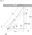
- Fig. 3 provided that the distal end of the discharge port of the carbon-source blowpipe is indicated by a point X, the point of intersection between the inner wall of the furnace and a line obtained by extending the central axis of the carbon-source blowing direction in a plan view seen from above is indicated by a point Y, a position on a side XY that is away from the point X by a distance 2/3 the length of the side XY is indicated by a point W, the distal end of the discharge port of the oxygen-blowing lance is indicated by a point Z, and the angle ⁇ XZW of a triangle ⁇ XWZ is indicated by an angle ⁇ 1 (°), it is found that if the oxygen-containing-gas blowing direction ⁇ 2 (°), which is open toward the Y side with respect to a side ZX passing through the distal end (point Z) of the discharge port of the oxygen
- the above condition is preferably satisfied in relation to at least one of the carbon-source blowpipes.
- the linear velocity of both the oxygen gas and the carbon source blown in decreases at a position away from the discharge port.
- the angle ⁇ 1 (°) may be determined from the facility drawing or may be calculated with reference to Expressions 1 to 3 below, for example, based on the law of cosines for triangles, using the respective lengths L XY (m), L YZ (m), and L XZ (m) of the sides XY, YZ, and XZ.
- low-nitrogen steel refers to steel with a nitrogen concentration of 40 ppm or less in a product.
- the range of the nitrogen concentration [N] that is 40 mass ppm or less in molten steel is assumed as a low nitrogen concentration range.
- it is preferable to set the effective ratio R of the time for the simultaneous supply of carbon and oxygen that satisfies the above condition with respect to the operation time to 30% or more.
- ultra-low nitrogen steel refers to steel with a nitrogen concentration of 25 ppm or less in a product.
- the range of the nitrogen concentration [N] that is 25 ppm or less in molten steel is defined as an ultra-low nitrogen concentration range.
- the present invention has been proposed based on the above studies. With the present invention, it is possible to stably reduce the nitrogen concentration in molten steel within a melting furnace or a refining furnace to a low nitrogen concentration range without the need for an enormous investment.
- Punched scrap (with a nitrogen content of approximately 22 mass ppm) was charged as the scrap 2 into an alternating-current electric arc furnace, in which approximately 60 to 70 tons of molten steel 5 having a carbon concentration of 0.03 to 0.06 mass% remained, at a weight of 10 to 15 tons at a time with the pusher 3. At the same time, the scrap 2 was melted using an arc from the graphite electrodes 4.
- an oxygen gas was blown into the molten steel at a rate of 40 to 50 Nm 3 /min from the oxygen-blowing lance 15 on the tapping side to carry out decarburization.
- the time t 2 (min) from the start of scrap melting due to the start of current flow to the start of tapping the molten steel from the furnace was in the range of 50 to 60 minutes, and the carbon concentration [C] in the molten steel tapped from the electric furnace was in the range of 0.03 to 0.06 mass%.
- the respective angles ⁇ 1 were found to be 95° and 105°.
- the respective angles ⁇ 1 were found to be 40° and 85°.
- the denitrification behavior was confirmed by adjusting as appropriate the oxygen blowing direction ⁇ 2 as well as the effective ratio R of the time for simultaneously supplying carbon and oxygen.
- the temperature of the obtained molten steel was found to be 1590 to 1600°C, the amount of melt was found to be 210 to 220 tons per process, and the volume of slag was found to be 100 to 150 kg/ton of molten steel.
- Table 2 shows the operating conditions and results. [Table 2] Test No.
- Test Nos. 1 to 5 in which the angle ⁇ 2 of the oxygen blowing direction on the slag removal side or the tapping side satisfies the condition that the angle ⁇ 2 has a positive value and is ⁇ 1 or less with respect to any one of the carbon-source supply ports, corresponds to an invention example.
- Test No. 6 in which each of the angles ⁇ 2 of the oxygen blowing directions on the slag removal side and the tapping side with respect to the carbon-source supply ports on the slag removal side and the tapping side is 0 or has a negative value or is more than the angle ⁇ 1 , corresponds to a comparative example.
- the nitrogen concentration [N] in the molten steel at tapping is 1/2 that of the comparative example or less.
- the nitrogen concentration [N] in the molten steel at tapping is about 1/4 that of the comparative example, which is in the low nitrogen concentration range ( ⁇ 40 mass ppm).
- the nitrogen concentration [N] in the molten steel at tapping is in the ultra-low nitrogen concentration range ( ⁇ 25 mass ppm).
- N added to the unit of the volume of a gas represents the volume in the standard state, that is, at a temperature of 0°C and a pressure of 101325 Pa.
- the present invention is industrially advantageous.
Landscapes
- Chemical & Material Sciences (AREA)
- Engineering & Computer Science (AREA)
- Materials Engineering (AREA)
- Metallurgy (AREA)
- Organic Chemistry (AREA)
- Manufacturing & Machinery (AREA)
- Refinement Of Pig-Iron, Manufacture Of Cast Iron, And Steel Manufacture Other Than In Revolving Furnaces (AREA)
- Treatment Of Steel In Its Molten State (AREA)
Abstract
Description
- The present invention relates to a method for denitrifying molten steel by supplying an oxygen-containing gas and a carbon source thereto during a step of producing steel by processing an iron source raw material, such as scrap, reduced iron, and pig iron, in a melting furnace or a refining furnace.
- Nitrogen is a component detrimental to metallic materials. In the conventional steelmaking process, nitrogen [N] in molten iron is removed by being adsorbed onto the surfaces of bubbles of carbon monoxide (CO) that are mainly generated during the decarburization of molten pig iron. Since molten steel with a low carbon concentration generates a limited amount of carbon monoxide, it is impossible to reduce the nitrogen concentration in the molten steel to a low concentration using such a method. Herein, "molten iron" refers to molten metal mainly composed of iron, that is, molten metal in which the content of iron is over 50%. Examples of molten iron include molten pig iron, molten steel, a molten cold iron source, and molten metal having the mixture.
- Meanwhile, a reduction in CO2 emissions is demanded for global environmental protection. To this end, it is necessary to shift the steelmaking process from the conventional method that involves using a blast furnace and a converter to a method of melting scraps or reduced iron. In such a case, however, the obtained molten iron has a low carbon concentration, which may make it impossible to form low-nitrogen steel for the above reason.
- In response, there have been proposed several methods for effectively denitrifying molten steel by reacting carbon [C] and an oxygen-containing gas in the molten steel within an electric furnace, and then utilizing bubbles of carbon monoxide generated by the reaction. For example,
Patent Literature 1 discloses limiting conditions, such as the carbon blowing rate and the oxygen supply rate to molten steel, and also limiting the nitrogen concentration (≤ 3 vol.%) in a carrier gas for blowing carbon into the molten steel.Patent Literature 1 also discloses that promoting denitrification and suppressing nitrogen adsorption at the same time can reduce the nitrogen concentration [N] in the molten steel to 25 mass ppm or less at the termination of refining. - In addition,
Patent Literature 2 discloses that a hydrocarbon-containing gas is used as a carrier gas for blowing a carbon source into molten steel.Patent Literature 2 also discloses that it is possible to obtain the effects of promoting carburization and reducing the nitrogen concentration [N] in the molten steel to less than about 20 mass ppm compared to when air is used as the carrier gas. - Further,
Patent Literature 3 discloses that carbon and oxygen are injected simultaneously but separately into the same zone within a furnace.Patent Literature 3 also discloses that the denitrification of molten steel improves by about 5 mass ppm compared to when oxygen is injected alone. -
- Patent Literature 1:
JP-H11-012634A - Patent Literature 2:
JP-H03-028312A - Patent Literature 3:
PCT International Application Publication No. 2002-533566 - However, the conventional technologies have the following problems. Typically, air or a nitrogen gas is used as a carrier gas for blowing a carbon source into molten steel in an electric furnace. In contrast, each of the methods described in
Patent Literature 1 andPatent Literature 2 uses an argon gas or a hydrocarbon-containing gas as a carrier gas. This requires a huge investment in facilities and equipment, such as a pipe for introducing the gas, which is different from ordinary gas, and a gas storage tank. - In addition, in the method described in
Patent Literature 3, carbon is injected around an oxygen injection zone. In the carbon injection zone, a carbon concentration can be achieved that is locally higher than the carbon concentration (i.e., the mean carbon concentration in the steel bath) in the non-carbon injection zone. This has significance as the generation of a carbon monoxide gas is promoted in such a zone. However, there is no disclosure about the definition of such a local zone, that is, the acceptable distance between the carbon injection portion and the oxygen injection portion, and just "about 20 cm distance" is indicated as an example. A blowpipe for a carbon source is often of a type embedded in the wall of a furnace. In such a case, in order to inject carbon around the oxygen injection zone, it is necessary to separately provide a carbon source lance and a lance position adjustment device, as well as modify other equipment, which is not realistic. - The present invention has been made in view of the above circumstances and aims to propose a technology capable of stably reducing the nitrogen concentration in molten steel in a melting furnace or a refining furnace to a low nitrogen concentration range without requiring a huge investment.
- A method for denitrifying molten steel according to the present invention which advantageously solves the above problems is a method for denitrifying molten steel involving supplying an oxygen-containing gas, and a carbon source carried by a carrier gas to the molten steel charged into a melting furnace or a refining furnace, characterized in that the oxygen-containing gas and the carbon source are simultaneously blown onto the molten steel under a condition that, provided that a triangle ΔXYZ is defined by connecting, in a plan view seen from above, a distal end (point X) of a discharge port of a carbon-source blowpipe; an intersection point (point Y) between an inner wall of the furnace and a line obtained by extending a central axis of a carbon source blowing direction; and a distal end (point Z) of a discharge port of an oxygen-blowing lance, that a point W is positioned on a side XY that is away from the point X by a
distance 2/3 a length of the side XY, and that an angle θ1(°) is an angle ∠XZW, an angle θ2(°) of an oxygen-containing-gas blowing direction that is open toward a Y side with respect to a side ZX passing through the distal end (point Z) of the discharge port of the oxygen-blowing lance in the plan view seen from above is a positive value and is the angle θ1 or less. - Note that the method for denitrifying molten steel according to the present invention may include the following features that are considered to be preferable solution means.
- (a) When the carbon-source blowpipe includes a plurality of carbon-source blowpipes, the above condition is satisfied with respect to at least one of the carbon-source blowpipes.
- (b) A time t1 (min) for simultaneously supplying the carbon source and the oxygen-containing gas from the carbon-source blowpipe and the oxygen-blowing lance, respectively, is set to at least 30% or more of a time t2 (min) taken from a start of melting a cold iron source to a start of tapping the molten steel from the furnace.
- (c) The point W is positioned at a middle point of the side XY.
- (d) The melting furnace is an electric furnace.
- According to the method for denitrifying molten steel of the present invention, it is possible to stably reduce the nitrogen concentration in molten steel in a melting furnace or a refining furnace to a low nitrogen concentration range without requiring a huge investment.
-
- [
Fig. 1] Fig. 1 is a schematic view of an example of an apparatus for implementing the present invention in whichFig. 1(a) represents a longitudinal sectional view, andFig. 1(b) represents a plan view seen from above. - [
Fig. 2] Fig. 2 is a schematic view of an overview of an experiment for inspecting the influence of the directions in which an oxygen gas and carbon are simultaneously blown in on denitrification, in whichFig. 2(a) represents a case where an oxygen-containing gas is blown in from an oxygen-blowing lance on the slag removal side, andFig. 2(b) represents a case where an oxygen-containing gas is blown in from an oxygen-blowing lance on the tapping side. - [
Fig. 3] Fig. 3 is a schematic view showing the blowing direction for, when an oxygen-containing gas and a carbon source are simultaneously blown in, the oxygen-containing gas that is preferred for denitrification. - [
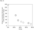
Fig. 4] Fig. 4 is a graph showing the influence of the ratio R(%) of the time for simultaneously supplying an oxygen-containing gas and a carbon source on the nitrogen concentration in molten steel according to the present invention. - An embodiment of the present invention will be specifically described below. Note that the drawings are only schematic, and thus may differ from the actual ones. In addition, the following embodiment only illustrates examples of an apparatus and a method for embodying the technical idea of the present invention. Thus, the configuration of the present invention is not limited thereto. That is, the technical idea of the present invention may be changed in various ways within the technical scope recited in the claims.
-
Fig. 1 shows an example of a preferred apparatus configuration for implementing the present invention. In the example ofFig. 1 , an electric arc furnace is used for a refining vessel as a melting furnace.Scrap 2, which has been fed into afurnace body 1 of the electric arc furnace from a skip car or a crane bucket, for example, is pushed into thefurnace body 1 with apusher 3. An arc is then generated fromgraphite electrodes 4 to melt thescrap 2 as a cold iron source so thatmolten steel 5 is obtained. At the same time, aflux 7 is added into themolten steel 5 from ahopper facility 6 above the furnace so thatslag 8 is obtained. To promote the melting of thescrap 2, an oxygen-containinggas 11 is blown from anoxygen pipe system 9 toward themolten steel 5 on the scrap-charging side through an oxygen-blowinglance 10 on the slag removal side. At the same time, a carbon source andcarrier gas 14 are blown onto themolten steel 5 from a carriergas pipe system 12 through a carbon-source blowpipe 13 for the purpose of increasing the carbon concentration within themolten steel 5 or shielding themolten steel 5 from the atmosphere due to the foaming of theslag 8. In the example ofFig. 1 , the carbon-source blowpipe 13 is horizontally embedded in afurnace wall 19. As the melting of the scrap proceeds, the oxygen-containinggas 11 is blown onto themolten steel 5 also from an oxygen-blowinglance 15 on the tapping side. After a predetermined time has elapsed, the supply of the oxygen-containinggas 11, the carbon source, and thecarrier gas 14 is stopped. At the same time, the arc conduction from thegraphite electrodes 4 is stopped, and theslag 8 is partially discharged to the outside of the furnace from aslag removal port 16. Themolten steel 5 is then tapped from the furnace through a tappingport 17. - Examples of melting furnaces or refining furnaces include not only electric arc furnaces but also induction melting furnaces and ladle refining furnaces. The cold iron source can be not only scrap but also reduced iron. Preferably, the cold iron source is an iron source produced with renewable energy. It should be noted that the reduced iron herein is directed to the commonly available one. The oxygen-containing
gas 11 can be a pure oxygen gas or a gas formed by diluting an oxygen gas. The diluent gas preferably does not contain nitrogen to promote denitrification. Examples of the diluent gas include an argon gas and a carbon dioxide gas. For example, air can be used as the carrier gas for the carbon source. - With respect to the above process, the inventors have made a detailed study of the influence of a blowing direction and a blowing condition on denitrification when the oxygen-containing
gas 11, the carbon source, and thecarrier gas 14 are blown in simultaneously but separately using an electric arc furnace similar to that shown inFig. 1 . - During the study, powdered carbon as the carbon source was blown onto the
molten steel 5 together with air as the carrier gas with its blowing direction fixed, as shown inFig. 2(a) and Fig. 2(b) . At the same time, as shown inFig. 2(a) , an oxygen gas as the oxygen-containing gas was blown onto the molten steel in any of the directions O1 to O3 by changing the direction of a discharge port of the oxygen-blowinglance 10 on the slag removal side. In addition, as shown inFig. 2(b) , an oxygen gas was blown onto the molten steel in any one of the directions O4 to O6 by changing the direction of a discharge port of the oxygen-blowinglance 15 on the tapping side. - Assume that the respective distal ends of the discharge ports of the carbon-
source blowpipe 13a on the slag removal side and the carbon-source blowpipe 13b on the tapping side are indicated by a point X and a point x. The respective points of intersection between thefurnace wall 19 and the lines obtained by extending the central axes of the air as well as thepowdered carbon 14, which are blown in from the respective carbon-source blowpipes, in a plan view seen from above, are indicated by a point Y and a point y. The respective distal ends of the oxygen gas discharge ports on the slag removal side and the tapping side are indicated by a point Z and a point z. In addition, a position on a side XY that is away from the point X by adistance 2/3 the length of the side XY is indicated by a point W, and a position on a side xy that is away from the point x by adistance 2/3 the length of the side xy is indicated by a point w. First, as shown inFig. 2(a) , when an oxygen-containing gas is blown in from the oxygen-blowinglance 10 on the slag removal side, triangles each having as the vertex the distal end (point Z) of the oxygen gas discharge port on the slag removal side are represented by ΔXYZ, ΔXWZ, ΔxyZ, and ΔxwZ. At this time, the oxygen blowing direction O1 corresponds to a method of blowing in an oxygen gas when a line obtained by extending the central axis of the oxygen gas jet in the plan view seen from above lies outside each of the triangles ΔXWZ and ΔxwZ. The oxygen blowing directions O2 and O3 each correspond to a method of blowing in an oxygen gas when a line obtained by extending the central axis of the oxygen gas jet in the plan view seen from above lies inside the triangle ΔXWZ and, regarding the oxygen blowing direction O2, also inside the triangle ΔxwZ. - In addition, as shown in
Fig. 2(b) , when an oxygen-containing gas is blown in from the oxygen-blowinglance 15 on the tapping side, triangles each having as the vertex the distal end (point z) of the oxygen gas discharge port on the tapping side are represented by Δxyz, Δxwz, ΔXYz, and ΔXWz. At this time, the oxygen blowing direction O4 corresponds to a method of blowing in an oxygen gas when a line obtained by extending the central axis of the oxygen gas jet in the plan view seen from above lies outside each of the triangles Δxwz and ΔXWz. The oxygen blowing directions O5 and O6 each correspond to a method of blowing in an oxygen gas when a line obtained by extending the central axis of the oxygen gas jet in the plan view seen from above lies inside the triangle Δxwz and, for the oxygen blowing direction O5, also inside the triangle ΔXWz. - The time at which scrap was charged into the furnace and the supply of a current from the
graphite electrodes 4 was started was assumed as the start of melting (start of a process), and immediately powdered carbon was blown in with air as a carrier from the carbon-source blowpipe 13a on the slag removal side and the carbon-source blowpipe 13b on the tapping side. At the same time, as shown in Table 1, oxygen was blown in from the oxygen-blowinglance 10 on the slag removal side in one of the directions O1 to O3 for 15 to 45 minutes, and then, the blowing of oxygen was stopped. Immediately after that, oxygen was blown in from the oxygen-blowinglance 15 on the tapping side in one of the directions O4 to O6 for 15 to 45 minutes. After the supply of a current from thegraphite electrodes 4 was stopped, a sample of themolten steel 5 in the furnace was collected, and themolten steel 5 was tapped from the furnace. The sample was analyzed for the carbon concentration and the nitrogen concentration. - Note that all of the
scrap 2 charged into the furnace was punched scrap with a nitrogen concentration of about 22 mass ppm. As the carbon source charged into the furnace, powdered carbon blown in from the carbon-source blowpipes 13 and aggregated carbon added from thehopper facility 6 above the furnace were used. In addition, adjustment was performed to allow the molten steel to have a carbon concentration [C] of about 0.05 mass% upon termination of the process. Table 1 illustrates the results together with the conditions.[Table 1] Level Conditions on Slag Removal Side Conditions on Tapping Side Total Time t1 of Simultaneous Blowing Processing Time t2 Steel Composition Before Tapping Oxygen Blowing Carbon Blowing Simultaneous Blowing Oxygen Blowing Carbon Blowing Simultaneous Blowing Direction Time Time Time Direction Time Time Time [C] [N] min min min min min min min min mass% mass ppm 1 O1 45 60 45 O4 15 60 15 60 60 0.05 136 2 O1 45 60 45 O5 15 60 15 60 60 0.06 68 3 O1 45 60 45 O6 15 60 15 60 60 0.04 69 4 O1 40 60 40 O5 20 60 20 60 60 0.05 35 5 O1 35 60 25 O5 25 60 25 60 60 0.04 27 6 O1 15 60 15 O5 45 60 45 60 60 0.05 12 7 O2 20 60 20 O4 20 60 20 40 70 0.05 36 8 O2 20 60 20 O5 20 60 20 40 70 0.05 18 9 O2 20 60 20 O6 20 60 20 40 70 0.06 17 10 O3 30 60 30 O4 15 60 15 45 60 0.04 21 11 O3 30 60 30 O5 15 60 15 45 60 0.05 12 12 O3 30 60 30 O6 15 60 15 45 60 0.05 12 - As shown in Table 1, the carbon concentration [C] in each of the samples of
Levels 1 to 12 before tapping was about 0.05 mass%. Meanwhile, the nitrogen concentration [N] widely varied from 12 mass ppm to 136 mass ppm. Regarding the sample of the level where the oxygen-gas blowing direction includes one or both of O1 and O4, the nitrogen concentration is lower as the oxygen blowing time in that direction is shorter. It was found that the nitrogen concentration [N] can be stably reduced to 20 mass ppm or less with respect to the sample of the level where the oxygen gas blowing direction includes neither O1 nor O4. - The result shows that it is not always necessary to inject oxygen and carbon into the same zone as in
Patent Literature 3. As shown inFig. 3 , provided that the distal end of the discharge port of the carbon-source blowpipe is indicated by a point X, the point of intersection between the inner wall of the furnace and a line obtained by extending the central axis of the carbon-source blowing direction in a plan view seen from above is indicated by a point Y, a position on a side XY that is away from the point X by adistance 2/3 the length of the side XY is indicated by a point W, the distal end of the discharge port of the oxygen-blowing lance is indicated by a point Z, and the angle ∠ XZW of a triangle ΔXWZ is indicated by an angle θ1(°), it is found that if the oxygen-containing-gas blowing direction θ2(°), which is open toward the Y side with respect to a side ZX passing through the distal end (point Z) of the discharge port of the oxygen-blowing lance in the plan view seen from above, is a positive value and is θ1 or less, a high denitrification effect can be obtained with the simultaneous blowing of carbon and oxygen. This is because if the angle θ2 indicating the oxygen blowing direction is 0 or a negative value, it is concerned that the major portion of the oxygen jet will flow toward the furnace wall, which may cause wear damage to thefurnace wall 19. In addition, when a plurality of carbon-source blowpipes are provided, the above condition is preferably satisfied in relation to at least one of the carbon-source blowpipes. It should be noted that the linear velocity of both the oxygen gas and the carbon source blown in decreases at a position away from the discharge port. Thus, it is preferable to set the point W at a position closer to the point X with respect to the position that is away from the point X by adistance 2/3 the length of the side XY, and specifically set the point W at the middle point of the side XY. - The angle θ1(°) may be determined from the facility drawing or may be calculated with reference to
Expressions 1 to 3 below, for example, based on the law of cosines for triangles, using the respective lengths LXY (m), LYZ (m), and LXZ (m) of the sides XY, YZ, and XZ.


- Next, the results of the experiment shown in Table 1 were organized based on the effective time for the simultaneous supply of carbon and oxygen. The time taken from the start of melting scrap to the start tapping of molten steel from the furnace is assumed as t2 (min). The time during which carbon and oxygen are simultaneously supplied from the carbon-source supply port and the oxygen-containing gas supply port, respectively, while the above condition of the direction of oxygen blown in from the oxygen-blowing lance is satisfied with respect to at least one carbon-source blowpipe, is represented as t1 (min). The effective ratio of the time for simultaneously supplying carbon and oxygen was organized based on R = t1/t2 × 100(%). Then, it was found that as shown in
Fig. 4 , the nitrogen concentration [N] analyzed for the sample before tapping is lower as the ratio R of the simultaneous supply time is higher. - Typically, low-nitrogen steel refers to steel with a nitrogen concentration of 40 ppm or less in a product. Thus, the range of the nitrogen concentration [N] that is 40 mass ppm or less in molten steel is assumed as a low nitrogen concentration range. First, it is necessary to satisfy, with respect to at least one carbon-source blowpipe, a condition that the angle θ2(°), which is the angle of the oxygen blowing direction from the oxygen-blowing lance from the side XZ to the Y direction, is a positive value and is θ1 or less. Further, to achieve the low nitrogen concentration range, it is preferable to set the effective ratio R of the time for the simultaneous supply of carbon and oxygen that satisfies the above condition with respect to the operation time, to 30% or more. In addition, ultra-low nitrogen steel refers to steel with a nitrogen concentration of 25 ppm or less in a product. Thus, the range of the nitrogen concentration [N] that is 25 ppm or less in molten steel is defined as an ultra-low nitrogen concentration range. Herein, to achieve the ultra-low nitrogen concentration range, it is preferable to set the effective ratio R of the time for the simultaneous supply of carbon and oxygen, which can satisfy the above condition with respect to the operation time, to 45% or more.
- The present invention has been proposed based on the above studies. With the present invention, it is possible to stably reduce the nitrogen concentration in molten steel within a melting furnace or a refining furnace to a low nitrogen concentration range without the need for an enormous investment.
- Punched scrap (with a nitrogen content of approximately 22 mass ppm) was charged as the
scrap 2 into an alternating-current electric arc furnace, in which approximately 60 to 70 tons ofmolten steel 5 having a carbon concentration of 0.03 to 0.06 mass% remained, at a weight of 10 to 15 tons at a time with thepusher 3. At the same time, thescrap 2 was melted using an arc from thegraphite electrodes 4. Then, 1.8 tons of coke were added to the obtainedmolten steel 5 from above and powdered carbon was blown into the furnace together with an air carrier at a rate of 10 to 20 kg/min from the carbon-source blowpipe 13a on the slag removal side and at a rate of 20 to 30 kg/min from the carbon-source blowpipe 13b on the tapping side, so that themolten steel 5 was carburized. An oxygen gas was blown onto the molten steel at a rate of 60 to 70 Nm3/min from the oxygen-blowinglance 10 on the slag removal side. Then, immediately after the blowing of oxygen from the oxygen-blowinglance 10 on the slag removal side was stopped, an oxygen gas was blown into the molten steel at a rate of 40 to 50 Nm3/min from the oxygen-blowinglance 15 on the tapping side to carry out decarburization. The time t2 (min) from the start of scrap melting due to the start of current flow to the start of tapping the molten steel from the furnace was in the range of 50 to 60 minutes, and the carbon concentration [C] in the molten steel tapped from the electric furnace was in the range of 0.03 to 0.06 mass%. With respect to the relationship between the oxygen-blowinglance 10 on the slag removal side and the carbon-source blowpipe 13a on the slag removal side and the relationship between the oxygen-blowinglance 10 on the slag removal side and the carbon-source blowpipe 13b on the tapping side, the respective angles θ1 were found to be 95° and 105°. With respect to the relationship between the oxygen-blowinglance 15 on the tapping side and the carbon-source blowpipe 13a on the slag removal side and the relationship between the oxygen-blowinglance 15 on the tapping side and the carbon-source blowpipe 13b on the tapping side, the respective angles θ1 were found to be 40° and 85°. The denitrification behavior was confirmed by adjusting as appropriate the oxygen blowing direction θ2 as well as the effective ratio R of the time for simultaneously supplying carbon and oxygen. The temperature of the obtained molten steel was found to be 1590 to 1600°C, the amount of melt was found to be 210 to 220 tons per process, and the volume of slag was found to be 100 to 150 kg/ton of molten steel. Table 2 shows the operating conditions and results.[Table 2] Test No. Oxygen Blowing Conditions on Slag Removal Side Oxygen Blowing Conditions on Tapping Side R Steel Composition at Tapping Remarks Carbon Source on Slag Removal Side Carbon Source on Tapping Side Carbon Source on Slag Removal Side Carbon Source on Tapping Side θ1 θ2 θ1 θ2 θ1 θ2 θ1 θ2 [C] [N] ∘ ∘ ∘ ∘ ∘ ∘ ∘ ∘ % mass% mass ppm 1 95 170 105 110 40 -10 85 10 25 0.05 51 Invention Example 2 95 170 105 110 40 25 85 45 28 0.04 44 Invention Example 3 95 170 105 110 40 20 85 40 35 0.06 33 Invention Example 4 95 60 105 0 40 20 85 40 58 0.05 20 Invention Example 5 95 60 105 0 40 20 85 40 75 0.04 12 Invention Example 6 95 170 105 110 40 75 85 95 0 0.03 120 Comparative Example - Each of Test Nos. 1 to 5 in which the angle θ2 of the oxygen blowing direction on the slag removal side or the tapping side satisfies the condition that the angle θ2 has a positive value and is θ1 or less with respect to any one of the carbon-source supply ports, corresponds to an invention example. Test No. 6 in which each of the angles θ2 of the oxygen blowing directions on the slag removal side and the tapping side with respect to the carbon-source supply ports on the slag removal side and the tapping side is 0 or has a negative value or is more than the angle θ1, corresponds to a comparative example. With respect to the example of the invention, the nitrogen concentration [N] in the molten steel at tapping is 1/2 that of the comparative example or less.
- In Test No. 3 in which the effective ratio R of the time for simultaneously supplying carbon and oxygen is set to 30% or more, the nitrogen concentration [N] in the molten steel at tapping is about 1/4 that of the comparative example, which is in the low nitrogen concentration range (≤ 40 mass ppm). In each of Test Nos. 4 and 5 in which the effective ratio R of the time for simultaneously supplying carbon and oxygen is set to 45% or more, the nitrogen concentration [N] in the molten steel at tapping is in the ultra-low nitrogen concentration range (≤ 25 mass ppm).
- The unit used in this specification is converted as follows.
- The unit of mass: 1 ton = 1000 kg.
- Symbol "N" added to the unit of the volume of a gas represents the volume in the standard state, that is, at a temperature of 0°C and a pressure of 101325 Pa.
- According to the method for denitrifying molten steel of the present invention, it is possible to stably reduce the nitrogen concentration in molten steel within a melting furnace or a refining furnace to a low nitrogen concentration range without the need for an enormous investment. Thus, the present invention is industrially advantageous.
-
- 1 furnace body
- 2 scrap
- 3 pusher
- 4 graphite electrode
- 5 molten steel
- 6 hopper facility above furnace
- 7 flux
- 8 slag
- 9 oxygen pipe system
- 10 oxygen-blowing lance on slag removal side
- 11 oxygen-containing gas (i.e., oxygen)
- 12 pipe system for carbon source and carrier gas
- 13 carbon-source blowpipe
- 13a carbon-source blowpipe (on slag removal side)
- 13b carbon-source blowpipe (on tapping side)
- 14 carbon source and carrier gas (powdered carbon and air)
- 15 oxygen-blowing lance on tapping side
- 16 slag removal port
- 17 tapping port
- 18 exhaust gas
- 19 furnace wall
- X, x distal end of discharge port of carbon-source blowpipe
- Y, y intersection point between inner wall of furnace and central axis of carbon-source blowing direction in plan view seen from above
- Z, z distal end of oxygen discharge port of oxygen-blowing lance
- O1 to O6 and On oxygen blowing direction (central axis thereof) in plan view seen from above
Claims (7)
- A method for denitrifying molten steel comprising supplying an oxygen-containing gas and a carbon source carried with a carrier gas to the molten steel charged into a melting furnace or a refining furnace,
characterized in that
the oxygen-containing gas and the carbon source are simultaneously blown onto the molten steel under a condition that, provided that a triangle ΔXYZ is defined by connecting, in a plan view seen from above, a distal end (point X) of a discharge port of a carbon-source blowpipe; an intersection point (point Y) between an inner wall of the furnace and a line obtained by extending a central axis of a carbon source blowing direction; and a distal end (point Z) of a discharge port of an oxygen-blowing lance, that a point W is positioned on a side XY that is away from the point X by a distance 2/3 a length of the side XY, and that an angle θ1(°) is an angle ∠XZW, an angle θ2(°) of an oxygen-containing-gas blowing direction that is open toward a Y side with respect to a side ZX passing through the distal end (point Z) of the discharge port of the oxygen-blowing lance in the plan view seen from above is a positive value and is the angle θ1 or less. - The method for denitrifying molten steel according to claim 1, wherein
when the carbon-source blowpipe includes a plurality of carbon-source blowpipes, the condition is satisfied in relation to at least one of the carbon-source blowpipes. - The method for denitrifying molten steel according to claim 1, wherein
a time t1 (min) for simultaneously supplying the carbon source and the oxygen-containing gas from the carbon-source blowpipe and the oxygen-blowing lance, respectively, is set to at least 30% or more of a time t2 (min) taken from a start of melting a cold iron source to a start of tapping the molten steel from the furnace. - The method for denitrifying molten steel according to claim 2, wherein
a time t1 (min) for simultaneously supplying the carbon source and the oxygen-containing gas from the carbon-source blowpipe and the oxygen-blowing lance, respectively, is set to at least 30% or more of a time t2 (min) taken from a start of melting a cold iron source to a start of tapping the molten steel from the furnace. - The method for denitrifying molten steel according to any one of claims 1 to 4, wherein
the point W is positioned at a middle point of the side XY. - The method for denitrifying molten steel according to any one of claims 1 to 4, wherein
the melting furnace is an electric furnace. - The method for denitrifying molten steel according to claim 5, wherein
the melting furnace is an electric furnace.
Applications Claiming Priority (2)
| Application Number | Priority Date | Filing Date | Title |
|---|---|---|---|
| JP2022130502 | 2022-08-18 | ||
| PCT/JP2023/025699 WO2024038715A1 (en) | 2022-08-18 | 2023-07-12 | Method for denitrifying melted steel |
Publications (2)
| Publication Number | Publication Date |
|---|---|
| EP4563711A1 true EP4563711A1 (en) | 2025-06-04 |
| EP4563711A4 EP4563711A4 (en) | 2026-02-18 |
Family
ID=89615952
Family Applications (1)
| Application Number | Title | Priority Date | Filing Date |
|---|---|---|---|
| EP23854752.5A Pending EP4563711A4 (en) | 2022-08-18 | 2023-07-12 | METHOD FOR THE DENITRIFICATION OF MOLTEN STEEL |
Country Status (5)
| Country | Link |
|---|---|
| US (1) | US20260035759A1 (en) |
| EP (1) | EP4563711A4 (en) |
| JP (1) | JP7420322B1 (en) |
| KR (1) | KR20250027805A (en) |
| CN (1) | CN119654425A (en) |
Families Citing this family (1)
| Publication number | Priority date | Publication date | Assignee | Title |
|---|---|---|---|---|
| EP4682272A1 (en) * | 2023-03-16 | 2026-01-21 | Nippon Steel Corporation | Method for producing molten steel and arc furnace |
Family Cites Families (8)
| Publication number | Priority date | Publication date | Assignee | Title |
|---|---|---|---|---|
| JPH0328312A (en) | 1989-06-24 | 1991-02-06 | Nakayama Steel Works Ltd | Method of injecting solid carbon, aluminum ash or flux into molten steel in electric furnace steelmaking |
| JPH05156343A (en) * | 1991-12-02 | 1993-06-22 | Nippon Steel Corp | Manufacturing method of ultra low nitrogen steel |
| JPH0741828A (en) * | 1993-07-15 | 1995-02-10 | Nippon Steel Corp | Vacuum refining of molten steel |
| IT1280115B1 (en) * | 1995-01-17 | 1998-01-05 | Danieli Off Mecc | MELTING PROCEDURE FOR ELECTRIC ARC OVEN WITH ALTERNATIVE SOURCES OF ENERGY AND RELATED ELECTRIC ARC OVEN |
| JPH1112634A (en) | 1997-06-20 | 1999-01-19 | Nkk Corp | Method for producing low nitrogen molten steel by arc furnace |
| FR2787468B1 (en) | 1998-12-18 | 2001-12-07 | Lorraine Laminage | PROCESS FOR DENITRURATION OF MOLTEN STEEL DURING DEVELOPMENT |
| KR20150051055A (en) * | 2013-11-01 | 2015-05-11 | 동국제강주식회사 | A methode for low nitrogen of molten steel in an electric furnace |
| JP6413710B2 (en) * | 2014-12-02 | 2018-10-31 | 新日鐵住金株式会社 | Production method of high purity steel by DC arc electric furnace |
-
2023
- 2023-07-12 US US18/994,471 patent/US20260035759A1/en active Pending
- 2023-07-12 JP JP2023552548A patent/JP7420322B1/en active Active
- 2023-07-12 KR KR1020257002920A patent/KR20250027805A/en active Pending
- 2023-07-12 EP EP23854752.5A patent/EP4563711A4/en active Pending
- 2023-07-12 CN CN202380057923.8A patent/CN119654425A/en active Pending
Also Published As
| Publication number | Publication date |
|---|---|
| US20260035759A1 (en) | 2026-02-05 |
| JPWO2024038715A1 (en) | 2024-02-22 |
| CN119654425A (en) | 2025-03-18 |
| EP4563711A4 (en) | 2026-02-18 |
| JP7420322B1 (en) | 2024-01-23 |
| KR20250027805A (en) | 2025-02-27 |
Similar Documents
| Publication | Publication Date | Title |
|---|---|---|
| EP3572534B1 (en) | Desulfurization processing method of molten steel, and desulfurization agent | |
| EP4353845A1 (en) | Molten steel denitrification method, simultaneous denitrification and desulfurization treatment method, and steel production method | |
| JP2016108575A (en) | Method for producing high purity steel by direct current arc type electric furnace | |
| CN108148946B (en) | A kind of LF furnace refining process | |
| EP4328330A1 (en) | Method for refining molten iron | |
| RU2254380C1 (en) | Method of production of rail steel | |
| JP6011728B2 (en) | Hot metal dephosphorization method | |
| US20260035759A1 (en) | Method for denitrifying molten steel | |
| EP3992145A1 (en) | Method for removing phosphorus from phosphorus-containing substance, method for producing starting material for metal smelting or starting material for metal refining, and method for producing metal | |
| EP3674424A1 (en) | Smelting method for ultra-low carbon 13cr stainless steel | |
| EP4353843A1 (en) | Molten steel denitrification method and steel production method | |
| EP4324940A1 (en) | Method for dephosphorization of molten metal | |
| JP5585151B2 (en) | Anti-slipping method | |
| EP4353842B1 (en) | Molten steel denitrification method and steel production method | |
| EP4339302B1 (en) | Method for refining molten steel | |
| JP3577997B2 (en) | Hot metal desulfurization method | |
| KR20060012266A (en) | Direct alloy way of steel | |
| JP2002533566A (en) | A method for denitrifying molten steel during its production. | |
| JPS6063307A (en) | Converter steel making method of dead soft steel | |
| RU2148659C1 (en) | Method of pipe steel production | |
| WO2024038715A1 (en) | Method for denitrifying melted steel | |
| JPS63143216A (en) | Melting method for extremely low carbon and low nitrogen steel | |
| EP4682272A1 (en) | Method for producing molten steel and arc furnace | |
| JP2668568B2 (en) | Melting method of extremely low nitrogen steel | |
| JPH0873915A (en) | Dephosphorization and desulfurization refining method of hot metal |
Legal Events
| Date | Code | Title | Description |
|---|---|---|---|
| STAA | Information on the status of an ep patent application or granted ep patent |
Free format text: STATUS: THE INTERNATIONAL PUBLICATION HAS BEEN MADE |
|
| PUAI | Public reference made under article 153(3) epc to a published international application that has entered the european phase |
Free format text: ORIGINAL CODE: 0009012 |
|
| STAA | Information on the status of an ep patent application or granted ep patent |
Free format text: STATUS: REQUEST FOR EXAMINATION WAS MADE |
|
| 17P | Request for examination filed |
Effective date: 20250225 |
|
| AK | Designated contracting states |
Kind code of ref document: A1 Designated state(s): AL AT BE BG CH CY CZ DE DK EE ES FI FR GB GR HR HU IE IS IT LI LT LU LV MC ME MK MT NL NO PL PT RO RS SE SI SK SM TR |
|
| DAV | Request for validation of the european patent (deleted) | ||
| DAX | Request for extension of the european patent (deleted) | ||
| A4 | Supplementary search report drawn up and despatched |
Effective date: 20260121 |
|
| RIC1 | Information provided on ipc code assigned before grant |
Ipc: C21C 7/00 20060101AFI20260115BHEP Ipc: C21C 5/52 20060101ALI20260115BHEP Ipc: C21C 7/04 20060101ALI20260115BHEP Ipc: C21C 7/072 20060101ALI20260115BHEP |