EP4563283A1 - Spannwerkzeug - Google Patents
Spannwerkzeug Download PDFInfo
- Publication number
- EP4563283A1 EP4563283A1 EP24213048.2A EP24213048A EP4563283A1 EP 4563283 A1 EP4563283 A1 EP 4563283A1 EP 24213048 A EP24213048 A EP 24213048A EP 4563283 A1 EP4563283 A1 EP 4563283A1
- Authority
- EP
- European Patent Office
- Prior art keywords
- longitudinal
- profile
- tool
- face
- fixing
- Prior art date
- Legal status (The legal status is an assumption and is not a legal conclusion. Google has not performed a legal analysis and makes no representation as to the accuracy of the status listed.)
- Pending
Links
Images


Classifications
-
- B—PERFORMING OPERATIONS; TRANSPORTING
- B25—HAND TOOLS; PORTABLE POWER-DRIVEN TOOLS; MANIPULATORS
- B25B—TOOLS OR BENCH DEVICES NOT OTHERWISE PROVIDED FOR, FOR FASTENING, CONNECTING, DISENGAGING, OR HOLDING
- B25B5/00—Clamps
- B25B5/04—Clamps with pivoted jaws
-
- B—PERFORMING OPERATIONS; TRANSPORTING
- B25—HAND TOOLS; PORTABLE POWER-DRIVEN TOOLS; MANIPULATORS
- B25B—TOOLS OR BENCH DEVICES NOT OTHERWISE PROVIDED FOR, FOR FASTENING, CONNECTING, DISENGAGING, OR HOLDING
- B25B31/00—Hand tools for applying fasteners
- B25B31/005—Hand tools for applying fasteners for temporarily connecting sheets before or during assembly operations
Definitions
- the present invention relates to an assembly comprising a tool and two profiles, the tool enabling the two profiles to be clamped and temporarily held together.
- the tool is particularly suitable for holding a tap in position on a joinery frame in order to enable their subsequent fixing by screwing.
- the invention also relates to a method for assembling two profiles using this tool.
- a piece of joinery whether it is a window, a door, a French window, conventionally comprises a fixed frame (fixed) and an opening (movable frame) and closes an opening in a wall.
- cladding profiles are assembled to the profiles of the frame of the joinery.
- the cladding profiles allow the thickness of the joinery to be increased to adapt to the thickness of the wall insulation.
- These cladding profiles therefore have different dimensions depending on the thickness of the insulation of the wall to which the joinery is intended.
- These cladding profiles are commonly, and indifferently, called added tapées, false tapées, or even thickness furrings.
- the added tapées and the profiles of the frame are made in one piece and form a single unit, called a pre-frame frame.
- One of the disadvantages of the pre-frame frame is that it is necessary to have as many pre-frame frames as there is wall insulation thickness.
- the added taps and the frame profiles are separate parts which are assembled together in the workshop, by screwing, before installation on site.
- the installation tool can be advantageously made of different materials, such as plastic or composite materials, making it light and very handy.
- the fixing member when the tool is in the unlocking position, the fixing member is arranged so that the first flat rectilinear portion of the first part of the head, with the first flat rectilinear portion of the associated rim, is opposite the fixing element.
- the fixing member when the tool is in the locking position, the fixing member is arranged so that the second flat rectilinear portion of the first part of the head, with the second flat rectilinear portion of the associated rim, is opposite the fixing element.
- the first profile is a frame profile and the second profile is an added panel.
- the installation tool thus allows the added tap and the frame profile to be locked in position, while compressing the longitudinal sealing joint of the added tap, and allowing it to be fixed to the frame profile in an efficient position to guarantee the watertightness of the joinery.
- the second profile is held on the first profile by a simple rotation, in one direction of rotation, of the second member relative to the first member.
- the removal of the installation tool is carried out by a simple rotation, in the opposite direction of rotation, of the second member relative to the first member.
- tool 100 A tool for clamping and holding two profiles in position, according to an exemplary embodiment, is now described and illustrated in the figures 3 to 8 . In the remainder of the description, the tool for clamping and holding two profiles in position will simply be referred to as tool 100.
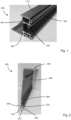
- the profile of the frame 500 is a hollow profile having a first longitudinal flat face 510, and preferably a second opposite longitudinal flat face 520, as illustrated in the Figure 1 .
- the profile of the frame 500 comprises, as illustrated in the Figure 1 , a longitudinal groove 530.
- the longitudinal groove 530 preferably extends over the entire length of the frame profile 500.
- Said longitudinal groove is intended to receive and cooperate with the added tap 600 and thus has a function of guiding and positioning the added tap 600 in the frame profile 500.
- This longitudinal groove 530 is preferably open towards the first longitudinal flat face 510.
- the frame profile 500 further comprises a longitudinal bearing surface 540.
- the longitudinal bearing surface 540 preferably extends over the entire length of the frame profile 500. Said longitudinal bearing surface is intended to form a bearing surface for the tool 100.
- the longitudinal bearing surface 540 is extended by a longitudinal edge 550. The longitudinal edge 550 is directed towards the second longitudinal flat face of the frame profile.
- Said longitudinal bearing surface 540 is preferably arranged opposite the longitudinal groove 530, in other words, that is to say open towards the second longitudinal flat face 520 of the frame profile.
- the longitudinal support surface 540 is preferably arranged, on the frame profile 500, under the longitudinal groove 530.
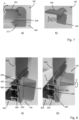
- the added tap 600 is also in the form of a longitudinal profile.
- the added tap 600 has two opposite longitudinal ends, called first 610 and second 620 longitudinal ends, as illustrated on the Figure 2
- the two longitudinal ends 610, 620 are connected to each other by a longitudinal edge 630.
- the longitudinal edge 630 has, between the two longitudinal ends, a width corresponding to a predefined insulation thickness of a wall.
- the reported type 600 compote as illustrated in the Figure 2 , a longitudinal groove 640.
- This longitudinal groove 640 is preferably arranged at the first longitudinal end 610.
- Said longitudinal groove 640 is preferably open at the first longitudinal end 610.
- This longitudinal groove 640 preferably extends over the entire length of the added tap 600.
- Said longitudinal groove of the added tap 600 is intended to receive a longitudinal sealing joint 700.
- the longitudinal sealing joint 700 is preferably a so-called dry joint.
- the longitudinal sealing joint 700 is intended to bear on the first longitudinal flat face 510 of the frame profile 500, when the added tap 600 is assembled to the frame profile 500.
- the added tap 600 comprises a longitudinal tab 650 which extends from the first longitudinal end 610 of the added tap 600.
- the longitudinal tab 650 is intended to cooperate with the longitudinal groove 530 of the frame profile 500.
- the longitudinal leg 650 of the added tap 600 and the longitudinal groove 530 of the frame profile 500 are assembled by clipping.
- the added tap 600 further comprises a longitudinal bearing surface 660.
- the longitudinal bearing surface 660 is located at the first longitudinal end 610 of the added tap 600. This longitudinal bearing surface 660 preferably extends over the entire length of the added tap 600. Said longitudinal bearing surface is intended to form another bearing surface for the tool 100.
- the longitudinal bearing surface 660 of the added tap 600 is extended by a longitudinal edge 670. The longitudinal edge 670 is directed towards the second end 620 of the added tap 600.
- the longitudinal sealing joint 700 rests on the first longitudinal flat face 510 of the frame profile 500 and the tab longitudinal 650 of the added tap 600 is inserted into the longitudinal groove 530 of the frame profile 500.
- the longitudinal bearing surface 660 of the added tap 600 and the longitudinal bearing surface 540 of the frame profile 500 are arranged substantially in the same plane.
- the 500 frame profile and the 600 insert are assembled by screwing.
- the first member 200 further comprises a through opening 230 in its thickness.
- the second member 300 of the tool 100 comprises a first body 310, cylindrical, centered on the axis of rotation A.
- the first body 310 passes through the first member 200, via the through opening 230 of said first member.
- the first body 310 has two ends, a first end 311 located on the side of the first face 210 of the first member 200 and a second end 312 located on the side of the second face 220 of the first member 200.
- the first body 310 is a straight cylinder with a circular cross-section.
- the second member 300 comprises a second body 320 fixedly connected to the first body 310.
- the second body 320 is fixedly connected to the first body 310 at the second end 312 of the first body.
- the second body 320 advantageously forms a gripping handle for an operator using the tool 100.
- the second member 300 comprises a third body, called head 330, fixedly connected to the first body 310.
- the head 330 is fixedly connected to the first body 310 at the first end 311 of the first body 310.
- the head 330 has a transverse dimension greater than the dimension of the first body 310 so as to form a shoulder over all or part of the circumference of said first body.
- the second member 300 is movable in rotation, relative to the first member 200, around the axis of rotation A, but is not movable in translation along this axis of rotation A.
- the first member 200 of the tool 100 comprises a fixing element 240 extending projecting from the first face 210 of said first member.
- the fixing element 240 is in the form of a projecting part, extending from the first face 210 of the first member 200, forming a longitudinal housing 250 provided with a longitudinal rim 260.
- the fixing element 240 is intended and configured to cooperate with one of the longitudinal bearing surfaces 660, 540 of the added tap 600 or of the frame profile 500.
- the fixing element 240 is intended and configured to cooperate with the longitudinal bearing surface 530 of the frame profile 500, as will be described later.
- the second member 300 of the tool 100 comprises a fixing member 340 at the level of the head 330.
- the fixing member 340 is intended and configured to cooperate with the other of the longitudinal bearing surfaces 660, 540 of the added tap 600 or of the frame profile 500.
- the fixing member 340 is intended and configured to cooperate with the longitudinal bearing surface 660 of the added tap 660, as will be described later.
- the tool 100 is configured to move at least between a so-called unlocking position and a so-called locking position.
- the unlocking position the fastening element 240 and the fastening member 340 are spaced apart from each other.
- the locking position the fastening element 240 and the fastening member 340 are brought closer to each other.
- the transition from the unlocked position to the locked position, and vice versa, is carried out by a rotation, along the rotation axis A, of the second member 300 relative to the first member 200.
- the rotation, along the axis of rotation A, of the second member 300 relative to the first member 200 advantageously causes the fixing member 340 to move closer to the fixing element 240.
- the transition from the unlocking position to the locking position, and vice versa is carried out by a rotation, along the axis of rotation A, of substantially 90° of the second member 300 relative to the first member 200.
- figures 4 to 6 illustrate the tool 100 in the unlocked position, with the gripping handle 320 arranged vertically
- the Figure 7 illustrates the tool 100 in the locking position, with the gripping handle 320 arranged horizontally.
- the head 330 is cylindrical, of non-circular cross-section.
- cross-section we mean a section in a plane perpendicular to the axis of symmetry A.
- the first flat rectilinear portion 351 of the first part 350 has a length greater than the second flat rectilinear portion 352.
- the axis of rotation A of the first body 310 is located at the level of the second part of the head 330.
- the head 330 comprises, at its first part 350, a rim 360.
- the rim 360 is an element projecting relative to the first part 350 of the head, and extends from this first part while being oriented radially relative to said head, that is to say substantially perpendicular to the axis of the head 330 and to the axis of rotation A.
- the first part 350 of the head 330 and the rim 360 of the head 330 advantageously form the fixing member 340.
- the fixing member 340 when the tool 100 is in the unlocked position, the fixing member 340 is arranged so that the first flat rectilinear portion 351 of the first part 350, with the first rectilinear portion 361 of the associated rim 360, is opposite the fixing element 240, as illustrated in view b) of the Figure 4 .
- the fixing member 340 When the tool 100 is in the locking position, the fixing member 340 is arranged so that the second flat rectilinear portion 352 of the first part 350, with the second rectilinear portion 362 of the associated rim 360, is opposite the fixing element 240, as illustrated in view a) of the Figure 7 .
- the head 330 being eccentric relative to the first body 310, the distance between the second flat rectilinear portion 352 of the first part 350 of the head 350 and the longitudinal housing 250 of the fixing element 240, when the tool 100 is in the locking position, is less than the distance between the first flat rectilinear portion 351 of the first part 350 of the head 330 and the longitudinal housing 250 of the fixing element 240, when the tool 100 is in the unlocking position.
- a method for assembling the added tap 600 on the frame profile 500 by means of the tool 100 is now described and illustrated in the figure 8 .
- the tool 100 is placed in the unlocking position, as illustrated in the Figure 6 .
- the added tap 600 is positioned on the frame profile 500.
- the operator positions the longitudinal tab 650 of the added tab 600 in the longitudinal groove 530 of the frame profile 500.
- the longitudinal tab 650 of the added tab 600 can be inserted into the longitudinal groove 530 of the frame profile 500 by clipping.
- the longitudinal sealing joint 700 which projects from the longitudinal groove 640 of the added tap 600 comes to bear against the frame profile 500, more precisely against the first longitudinal flat face 510 of the frame profile 500.
- the longitudinal bearing surface 660 of the added tap 600 and the longitudinal bearing surface 540 of the frame profile 500 are arranged substantially in the same plane, as illustrated in the figures 3 And 8 .
- the added tap 600 is temporarily blocked on the frame profile 500 by means of one or more tools, depending on the length of the frame profile 500 and the added tap 600.
- the operator positions the tool 100 so that the fixing element 240 of the first member 200 comes opposite the surface longitudinal support surface 540 of the frame profile 500 and that the fixing member 340 of the second member 300 comes opposite the longitudinal support surface 660 of the added tap 600, as illustrated in view a) of the figure 8 .
- the tool 100 is sized so that in the unlocked position, the distance between the fixing element 240 and the fixing member 340 is greater than the distance between the bearing surfaces 660, 540 of the added tap 600 and the frame profile 500, as illustrated in view a) of the figure 8 .
- the operator places the tool 100 in the locking position.
- the operator rotates the second member 300 around the axis of rotation A, relative to the first member 200, by means of the gripping handle 320, in the direction of rotation R, as illustrated in view b) of the figure 8 .
- the operator moves the gripping handle through a quarter turn, as illustrated by the arrow.
- the rotation of the gripping handle 320 causes the fixing member 340 of the second member 300 to move closer to the fixing element 240 of the first member 200, until the fixing element 240 of the first member 200 comes to bear on the longitudinal bearing surface 540 of the frame profile 500 and the fixing member 340 of the second member 300 comes to bear on the longitudinal bearing surface 660 of the added tap 600, as illustrated in view b) of the figure 8 .
- the tool 100 thus makes it possible to temporarily hold and block in position the added tap 600 on the frame profile 500, while compressing the longitudinal sealing joint 700 of the added tap 600 on the first longitudinal flat face 510 of the frame profile 500.
- the tool forms, with the frame profile and the added tap, a solid assembly.
- the operator positions a new tool 100, at a distance from the previous one, for example approximately every 50 cm.
- each tool 100 generates, over the length of the frame profile 500 and the added tap 600, a positioning that is compliant with the sealing of the added tap 600 before the latter is locked onto the frame profile 500 by screwing.
- the added tap 600 is fixed to the frame profile 500 by screwing.
- a plurality of fixing holes can be made in the frame profile 500 to allow the passage of screws. These fixing holes are through holes so that it is possible to pass a screw inside each fixing hole.
- each tool 100 is removed.
- the operator places tool 100 in the unlocking position.
- the operator rotates the second member 300 around the axis of rotation A, relative to the first member 200, by means of the gripping handle 320, in the opposite direction to the direction of rotation. R, until returning to the unlocked position.
- the rotation of the gripping handle 320 causes the fixing member 340 of the second member 300 to move away from the fixing element 240 of the first member 200.
- the operator can remove the tool 100 and can use the tool again to temporarily assemble a new tapped insert with a new frame profile.
- the present invention achieves the objectives it set for itself.
- it presents a light, reusable, and ergonomic tool which makes it possible to lock the added tap 600 and the frame profile 500 in position, while compressing the longitudinal sealing joint 700 of the added tap, and to allow its fixing on the frame profile in an efficient position to guarantee the watertightness of the joinery.
- the tightening provided by the tool 100 is a rapid, controlled and constant tightening, with reduced effort for the operator who uses it.
- the tool 100 thus effectively replaces the clamps currently used.
- the tool can advantageously be made of different materials, such as for example plastic or composite materials.
- the tool 100 can be configured so that the fixing element 240 of the first member 200 cooperates with the longitudinal bearing surface 660 of the added tap 600 and the fixing member 340 of the second member 300 cooperates with the longitudinal bearing surface 540 of the frame profile 500.
- said fixing member may be in the form of a lug extending radially from the head.
- radially is meant perpendicular to the axis of rotation A.
- the lug is located at a distance from the first end of the first body, therefore at a distance from the first face of the first member.
- the lug When the tool is in the unlocked position, the lug is not facing the fastener. When the tool is in the locked position, the lug is facing the fastener.
Landscapes
- Engineering & Computer Science (AREA)
- Mechanical Engineering (AREA)
- Gripping On Spindles (AREA)
- Connection Of Plates (AREA)
Applications Claiming Priority (1)
| Application Number | Priority Date | Filing Date | Title |
|---|---|---|---|
| FR2312620A FR3155449B1 (fr) | 2023-11-17 | 2023-11-17 | Outil de serrage |
Publications (1)
| Publication Number | Publication Date |
|---|---|
| EP4563283A1 true EP4563283A1 (de) | 2025-06-04 |
Family
ID=89834461
Family Applications (1)
| Application Number | Title | Priority Date | Filing Date |
|---|---|---|---|
| EP24213048.2A Pending EP4563283A1 (de) | 2023-11-17 | 2024-11-14 | Spannwerkzeug |
Country Status (2)
| Country | Link |
|---|---|
| EP (1) | EP4563283A1 (de) |
| FR (1) | FR3155449B1 (de) |
Citations (8)
| Publication number | Priority date | Publication date | Assignee | Title |
|---|---|---|---|---|
| US1427893A (en) * | 1919-09-18 | 1922-09-05 | Harry D Babcock | Plate-tightening device |
| GB567474A (en) * | 1943-08-19 | 1945-02-15 | Gen Aircraft Ltd | Improvements in clamping devices |
| US3249351A (en) * | 1961-12-26 | 1966-05-03 | Wilfred A Smith | Clamp |
| DE20318000U1 (de) * | 2003-11-20 | 2005-04-21 | Westag & Getalit Ag | Verbindungsbeschlag |
| GB2459482A (en) * | 2008-04-24 | 2009-10-28 | Mark Clarke | Clamp with asymmetrical cam lever |
| US9045912B2 (en) * | 2012-09-15 | 2015-06-02 | Richard N. Fearn | Waler strongback clamp with cam |
| GB2548568A (en) * | 2016-03-21 | 2017-09-27 | Mark Broadbent Jeremy | Clamp |
| WO2021083882A1 (fr) * | 2019-10-31 | 2021-05-06 | Hydro Extruded Solutions As | Kit d'accessoire pour menuiserie, menuiserie comportant ledit kit d'accessoire et procédé de mise en œuvre dudit kit d'accessoire sur ladite menuiserie |
-
2023
- 2023-11-17 FR FR2312620A patent/FR3155449B1/fr active Active
-
2024
- 2024-11-14 EP EP24213048.2A patent/EP4563283A1/de active Pending
Patent Citations (8)
| Publication number | Priority date | Publication date | Assignee | Title |
|---|---|---|---|---|
| US1427893A (en) * | 1919-09-18 | 1922-09-05 | Harry D Babcock | Plate-tightening device |
| GB567474A (en) * | 1943-08-19 | 1945-02-15 | Gen Aircraft Ltd | Improvements in clamping devices |
| US3249351A (en) * | 1961-12-26 | 1966-05-03 | Wilfred A Smith | Clamp |
| DE20318000U1 (de) * | 2003-11-20 | 2005-04-21 | Westag & Getalit Ag | Verbindungsbeschlag |
| GB2459482A (en) * | 2008-04-24 | 2009-10-28 | Mark Clarke | Clamp with asymmetrical cam lever |
| US9045912B2 (en) * | 2012-09-15 | 2015-06-02 | Richard N. Fearn | Waler strongback clamp with cam |
| GB2548568A (en) * | 2016-03-21 | 2017-09-27 | Mark Broadbent Jeremy | Clamp |
| WO2021083882A1 (fr) * | 2019-10-31 | 2021-05-06 | Hydro Extruded Solutions As | Kit d'accessoire pour menuiserie, menuiserie comportant ledit kit d'accessoire et procédé de mise en œuvre dudit kit d'accessoire sur ladite menuiserie |
Also Published As
| Publication number | Publication date |
|---|---|
| FR3155449A1 (fr) | 2025-05-23 |
| FR3155449B1 (fr) | 2025-10-31 |
Similar Documents
| Publication | Publication Date | Title |
|---|---|---|
| EP0913613A1 (de) | Manschette für ein Rohrelement | |
| EP3213039A1 (de) | Vorrichtung und verfahren zur montage und ausrichtung eines sensors auf einem träger | |
| FR3046137A1 (fr) | Procede d'alignement d'un premier orifice d'une premiere piece avec un deuxieme orifice d'une deuxieme piece et kit pour sa mise en œuvre | |
| EP3988736A1 (de) | Vorrichtung zur befestigung einer platte in einer nut mittels spannkeilen, die auf einer seite der platte angeordnet sind | |
| FR3087218A1 (fr) | Ensemble de poignee pour ouvrants de type fenetre ou porte | |
| EP2425170B1 (de) | System zur befestigung eines verbinders für ein fluidtransportrohr an einer wand | |
| EP2795141B1 (de) | System zum befestigen eines objekts an einem element mit befestigungsrille(n) und befestigungsvorrichtung für ein solches system | |
| EP1156172B1 (de) | Klemme zur Verbindung von Komponenten verschiedener Stabwerke | |
| EP2415954B1 (de) | Einsatzbeschlag, der einen Befestigungsflansch umfasst | |
| FR2996610A1 (fr) | Ensemble comportant au moins deux planches assemblables transversalement et bout a bout au moyen d'au moins une equerre d'assemblage. | |
| FR2920015A3 (fr) | Structure de vehicule automobile et procede de fixation d'un accessoire | |
| EP2159344B1 (de) | Bügel für die Befestigung einer Strebe auf einem Pfosten | |
| FR3155449A1 (fr) | Outil de serrage | |
| EP2163703A1 (de) | Verbindung bzw. Gelenk zwischen zwei Hohlprofilen mit einstellbarem Winkel | |
| EP3162980A1 (de) | Verstrebungsvorrichtung für die verkleidung einer struktur | |
| FR2967187A1 (fr) | Garniture d'ouvrant a etancheite amelioree | |
| FR3080875A1 (fr) | Dispositif de maintien temporaire d'elements de construction et procede d'utilisation d'un tel dispositif | |
| FR2896020A1 (fr) | Dispositif de fixation et de reglage d'une piece sur un support | |
| EP2236713A1 (de) | Zweiteiliger Vierteldrehungsverschluss | |
| EP0992316B1 (de) | Handbetätigte Vorrichtung zur Richtigstellung der Position einer Elektrospindel bezüglich eines Trägers | |
| BE1029205B1 (fr) | Moyen de liaison métallique | |
| FR2895769A1 (fr) | Dispositif d'assemblage de pieces et procede d'assemblage de pieces utilisant un tel dispositif | |
| EP4265868B1 (de) | Befestigungsvorrichtung für einen griff | |
| FR2561965A1 (fr) | Etau perfectionne pour machines-outils plus particulierement pour fraiseuses | |
| FR2486845A1 (fr) | Appareil pour le positionnement angulaire de profiles divers en vue de leur assemblage par soudure notamment |
Legal Events
| Date | Code | Title | Description |
|---|---|---|---|
| PUAI | Public reference made under article 153(3) epc to a published international application that has entered the european phase |
Free format text: ORIGINAL CODE: 0009012 |
|
| STAA | Information on the status of an ep patent application or granted ep patent |
Free format text: STATUS: THE APPLICATION HAS BEEN PUBLISHED |
|
| AK | Designated contracting states |
Kind code of ref document: A1 Designated state(s): AL AT BE BG CH CY CZ DE DK EE ES FI FR GB GR HR HU IE IS IT LI LT LU LV MC ME MK MT NL NO PL PT RO RS SE SI SK SM TR |
|
| STAA | Information on the status of an ep patent application or granted ep patent |
Free format text: STATUS: REQUEST FOR EXAMINATION WAS MADE |
|
| 17P | Request for examination filed |
Effective date: 20250703 |
|
| GRAP | Despatch of communication of intention to grant a patent |
Free format text: ORIGINAL CODE: EPIDOSNIGR1 |
|
| STAA | Information on the status of an ep patent application or granted ep patent |
Free format text: STATUS: GRANT OF PATENT IS INTENDED |
|
| P01 | Opt-out of the competence of the unified patent court (upc) registered |
Free format text: CASE NUMBER: UPC_APP_8797_4563283/2025 Effective date: 20251002 |
|
| INTG | Intention to grant announced |
Effective date: 20251020 |