EP4559614A2 - Procédé et machine pour l'usinage par découpe d'une pièce - Google Patents
Procédé et machine pour l'usinage par découpe d'une pièce Download PDFInfo
- Publication number
- EP4559614A2 EP4559614A2 EP25169318.0A EP25169318A EP4559614A2 EP 4559614 A2 EP4559614 A2 EP 4559614A2 EP 25169318 A EP25169318 A EP 25169318A EP 4559614 A2 EP4559614 A2 EP 4559614A2
- Authority
- EP
- European Patent Office
- Prior art keywords
- workpiece
- cutting
- contour
- during
- remaining part
- Prior art date
- Legal status (The legal status is an assumption and is not a legal conclusion. Google has not performed a legal analysis and makes no representation as to the accuracy of the status listed.)
- Pending
Links
Images
Classifications
-
- B—PERFORMING OPERATIONS; TRANSPORTING
- B23—MACHINE TOOLS; METAL-WORKING NOT OTHERWISE PROVIDED FOR
- B23K—SOLDERING OR UNSOLDERING; WELDING; CLADDING OR PLATING BY SOLDERING OR WELDING; CUTTING BY APPLYING HEAT LOCALLY, e.g. FLAME CUTTING; WORKING BY LASER BEAM
- B23K26/00—Working by laser beam, e.g. welding, cutting or boring
- B23K26/02—Positioning or observing the workpiece, e.g. with respect to the point of impact; Aligning, aiming or focusing the laser beam
- B23K26/03—Observing, e.g. monitoring, the workpiece
- B23K26/032—Observing, e.g. monitoring, the workpiece using optical means
-
- B—PERFORMING OPERATIONS; TRANSPORTING
- B23—MACHINE TOOLS; METAL-WORKING NOT OTHERWISE PROVIDED FOR
- B23K—SOLDERING OR UNSOLDERING; WELDING; CLADDING OR PLATING BY SOLDERING OR WELDING; CUTTING BY APPLYING HEAT LOCALLY, e.g. FLAME CUTTING; WORKING BY LASER BEAM
- B23K26/00—Working by laser beam, e.g. welding, cutting or boring
- B23K26/02—Positioning or observing the workpiece, e.g. with respect to the point of impact; Aligning, aiming or focusing the laser beam
- B23K26/06—Shaping the laser beam, e.g. by masks or multi-focusing
- B23K26/062—Shaping the laser beam, e.g. by masks or multi-focusing by direct control of the laser beam
- B23K26/0622—Shaping the laser beam, e.g. by masks or multi-focusing by direct control of the laser beam by shaping pulses
-
- B—PERFORMING OPERATIONS; TRANSPORTING
- B23—MACHINE TOOLS; METAL-WORKING NOT OTHERWISE PROVIDED FOR
- B23K—SOLDERING OR UNSOLDERING; WELDING; CLADDING OR PLATING BY SOLDERING OR WELDING; CUTTING BY APPLYING HEAT LOCALLY, e.g. FLAME CUTTING; WORKING BY LASER BEAM
- B23K26/00—Working by laser beam, e.g. welding, cutting or boring
- B23K26/14—Working by laser beam, e.g. welding, cutting or boring using a fluid stream, e.g. a jet of gas, in conjunction with the laser beam; Nozzles therefor
- B23K26/142—Working by laser beam, e.g. welding, cutting or boring using a fluid stream, e.g. a jet of gas, in conjunction with the laser beam; Nozzles therefor for the removal of by-products
-
- B—PERFORMING OPERATIONS; TRANSPORTING
- B23—MACHINE TOOLS; METAL-WORKING NOT OTHERWISE PROVIDED FOR
- B23K—SOLDERING OR UNSOLDERING; WELDING; CLADDING OR PLATING BY SOLDERING OR WELDING; CUTTING BY APPLYING HEAT LOCALLY, e.g. FLAME CUTTING; WORKING BY LASER BEAM
- B23K26/00—Working by laser beam, e.g. welding, cutting or boring
- B23K26/36—Removing material
- B23K26/38—Removing material by boring or cutting
-
- B—PERFORMING OPERATIONS; TRANSPORTING
- B26—HAND CUTTING TOOLS; CUTTING; SEVERING
- B26F—PERFORATING; PUNCHING; CUTTING-OUT; STAMPING-OUT; SEVERING BY MEANS OTHER THAN CUTTING
- B26F1/00—Perforating; Punching; Cutting-out; Stamping-out; Apparatus therefor
-
- B—PERFORMING OPERATIONS; TRANSPORTING
- B26—HAND CUTTING TOOLS; CUTTING; SEVERING
- B26F—PERFORATING; PUNCHING; CUTTING-OUT; STAMPING-OUT; SEVERING BY MEANS OTHER THAN CUTTING
- B26F1/00—Perforating; Punching; Cutting-out; Stamping-out; Apparatus therefor
- B26F1/38—Cutting-out; Stamping-out
-
- B—PERFORMING OPERATIONS; TRANSPORTING
- B26—HAND CUTTING TOOLS; CUTTING; SEVERING
- B26F—PERFORATING; PUNCHING; CUTTING-OUT; STAMPING-OUT; SEVERING BY MEANS OTHER THAN CUTTING
- B26F1/00—Perforating; Punching; Cutting-out; Stamping-out; Apparatus therefor
- B26F1/38—Cutting-out; Stamping-out
- B26F1/3806—Cutting-out; Stamping-out wherein relative movements of tool head and work during cutting have a component tangential to the work surface
- B26F1/3813—Cutting-out; Stamping-out wherein relative movements of tool head and work during cutting have a component tangential to the work surface wherein the tool head is moved in a plane parallel to the work in a coordinate system fixed with respect to the work
-
- G—PHYSICS
- G01—MEASURING; TESTING
- G01N—INVESTIGATING OR ANALYSING MATERIALS BY DETERMINING THEIR CHEMICAL OR PHYSICAL PROPERTIES
- G01N21/00—Investigating or analysing materials by the use of optical means, i.e. using sub-millimetre waves, infrared, visible or ultraviolet light
- G01N21/84—Systems specially adapted for particular applications
- G01N21/88—Investigating the presence of flaws or contamination
- G01N21/8851—Scan or image signal processing specially adapted therefor, e.g. for scan signal adjustment, for detecting different kinds of defects, for compensating for structures, markings, edges
-
- B—PERFORMING OPERATIONS; TRANSPORTING
- B23—MACHINE TOOLS; METAL-WORKING NOT OTHERWISE PROVIDED FOR
- B23K—SOLDERING OR UNSOLDERING; WELDING; CLADDING OR PLATING BY SOLDERING OR WELDING; CUTTING BY APPLYING HEAT LOCALLY, e.g. FLAME CUTTING; WORKING BY LASER BEAM
- B23K26/00—Working by laser beam, e.g. welding, cutting or boring
- B23K26/12—Working by laser beam, e.g. welding, cutting or boring in a special atmosphere, e.g. in an enclosure
- B23K26/126—Working by laser beam, e.g. welding, cutting or boring in a special atmosphere, e.g. in an enclosure in an atmosphere of gases chemically reacting with the workpiece
Definitions
- the present invention relates to a method for cutting a workpiece, in particular a plate-like workpiece, for example a sheet metal, comprising: cutting the workpiece along a predetermined cutting contour to separate a workpiece part from a remaining part, and checking whether the workpiece part has been completely separated from the remaining part during the cutting process and determining that the workpiece part has not been completely separated from the remaining part.
- the invention also relates to a machine for cutting a workpiece, comprising: a processing head for aligning a processing beam onto the workpiece, at least one movement device for generating a relative movement between the processing head and the workpiece, a control device for controlling the at least one movement device to separate a workpiece part from a remaining part by cutting the workpiece along a predetermined cutting contour, and an evaluation device which is designed to check whether the workpiece part has been completely separated from the remaining part during the cutting process.
- the cutting of plate-like workpieces can be performed by thermal or mechanical processing.
- thermal processing using a processing beam e.g., a laser beam
- a workpiece part is completely separated from a residual part along a cutting contour.
- the residual part can be a residual workpiece or a residual skeleton of the workpiece, from which the workpiece part (good part) is cut free.
- the The part being cut free may be a residual part (waste), for example, a slug that may be cut free from a good part.
- the cutting contour used for the cut-free process may be a closed cutting contour, but this is not mandatory. For example, if an edge of the part to be cut forms an outer edge of the workpiece, the part can be cut free from the residual skeleton without cutting a closed cutting contour.
- Interference contours that do not fall are particularly critical on machines with moving axis elements or support carriages throughout the entire machining process.
- Machine elements, particularly moving machine elements can be damaged by slugs or good parts located partially below the workpiece plane.
- the workpiece can also be unintentionally moved or lifted by form closure, so that contour accuracy is no longer guaranteed. This can sometimes result in a poor cut or a non-cut, or the workpiece can be torn from the clamping elements on which the workpiece is typically mounted during cutting operations due to sufficient frictional connection to the moving machine elements.
- the WO 2015/080179 Al solves the problem of removing a large scrap piece when cutting a hole in a workpiece by inserting a plurality of cutting lines into the workpiece in the area of the hole to be cut, cutting the large scrap piece into several smaller pieces.
- the subsequent cutting of the hole along the contour line is performed starting from the scrap piece that is intended to be the last to fall down in the direction of the profile line of the hole.
- the DE 10 2009 049 750 A1 describes a method for cutting material along a desired cutting path by applying a plurality of laser pulses of a modulated laser beam.
- the cutting path is repeatedly traversed by the modulated laser beam, with at least one cutting parameter being changed between two passes. In this way, first laser cutting points introduced into the workpiece during a first pass of the cutting path can be offset to second laser cutting points introduced into the workpiece during a second pass of the cutting path.
- the object of the invention is to provide a method and a machine for cutting a workpiece, which enable the automated removal of interfering contours that occur when a workpiece part is incompletely separated from a remaining part.
- a method of the type mentioned above which is characterized by: Re-cutting the workpiece along a further cutting contour offset laterally to the predetermined cutting contour after determining that the workpiece part has not been completely separated from the remaining part.
- the further cutting contour extends at least along a section or partial area of the predetermined cutting contour and can, in particular, extend along the entire predetermined cutting contour.
- the further cutting contour is typically offset parallel to the predetermined cutting contour by a constant amount. If necessary, the amount by which the further cutting contour is offset from the specified cutting contour can vary along the further cutting contour.
- Cutting along the cutting contour is performed using a processing beam, usually a laser beam, but another type of processing beam, such as a plasma beam or a water jet, can also be used for this purpose.
- a suitable sensor or detector is first used to check whether post-processing is required after cutting to completely separate the workpiece part from the remaining part. If this is the case, further cutting is carried out along the cutting contour, specifically along a further cutting contour laterally offset from the predetermined cutting contour, in order to completely separate the workpiece part (good part) from the remaining part (waste) and thereby prevent the incompletely cut good part or remaining part from forming an interference contour during further cutting of the workpiece.
- the lateral offset is advantageous because, during further cutting along the predetermined cutting contour, i.e., without a lateral offset, damage to the edge of the good part is to be expected due to the edge region of the processing beam and/or due to movement of the remaining part within the cutting contour forming the cutting gap, which is caused by the gas pressure of the process gas.
- the further cutting contour is offset laterally toward the remaining part (waste), i.e., the distance to the good part is increased.
- the further cutting contour is offset laterally by an amount that is large enough to allow a cutting operation of the workpiece along the a processing beam directed onto the workpiece along a further cutting contour strikes a circumferential edge of the workpiece part with an intensity which is less than 50%, preferably less than 30%, in particular less than 20% of a maximum intensity of the processing beam.
- a processing beam e.g. in the form of a laser beam, generally has an intensity distribution across its beam cross-section which decreases from a maximum intensity, which is typically present at least in the center of the beam cross-section, towards the edge. While the maximum intensity is sufficient to melt the workpiece for cutting, this is typically not the case with the intensities occurring in the edge region of the laser beam, so that the processing beam, in particular the laser beam, can no longer damage the circumferential edge of the workpiece part.
- the additional cutting contour is offset laterally relative to the specified cutting contour by an amount of at least 2%, preferably at least 5%, of the cutting gap width of the specified cutting contour.
- Such a lateral offset generally ensures that the machining beam and/or slag formed during subsequent cutting do not damage the peripheral edge of the workpiece part.
- the further cutting contour is offset laterally from the specified cutting contour by an amount that is smaller than the cutting gap width of the specified cutting contour. If the process gas pressure used during cutting is kept constant, i.e., is also used for the subsequent cutting, then typically only a certain amount of the offset from the specified cutting contour is process-safe. If the further cutting contour is offset by a distance or by an amount that corresponds to the cutting gap width of the specified cutting contour, the doubling of the width of the cutting gap created in this way can cause disruptions in the cutting quality, even to the point of process interruption or faulty cuts, so that the cutting gap width of the specified cutting contour represents an upper limit for the amount of the offset of the further cutting contour. In addition, it is to be expected that as the amount of the lateral offset approaches the width of the cutting contour or When the cutting gap is widened again, more and more slag is released, which can reach the peripheral edge of the workpiece and become stuck there.
- the laterally offset cutting contour is traversed in the opposite machining direction to the specified cutting contour during the subsequent cutting process.
- the laterally offset cutting contour formed during the subsequent cutting process extends only along a section of the specified cutting contour.
- the specified cutting contour can be machined again completely or partially, i.e., along a partial section or a section, with the same and/or different cutting parameters (e.g., maximum laser power, feed rate, process gas pressure, etc.).
- the laterally offset cutting contour can be traversed in the same machining direction as the specified cutting contour or in the opposite machining direction to the specified cutting contour.
- the further cutting contour can be cut either partially or completely with an overlap to the beginning of the specified cutting contour.
- the testing as to whether the workpiece part has been separated from the remaining part comprises the following steps: irradiating a preferably pulsed processing beam onto the workpiece at a test position within the specified cutting contour, detecting radiation generated by an interaction between the processing beam and the workpiece, and evaluating the detected radiation to test whether the workpiece part has been completely separated from the remaining part during the cutting process, wherein during the irradiation of the processing beam, the intensity of the processing beam is increased at the test position and the irradiation of the processing beam is stopped as soon as it is determined during the testing that The workpiece part has not been completely separated from the remaining part during cutting operations.
- the processing beam used for the test can, in particular, be a laser beam.
- the pulsed processing beam irradiated onto the workpiece can be a single pulse of the processing beam, in particular a laser pulse, or a plurality of laser pulses.
- the processing beam is typically generated by the same beam source that also generates the processing beam for cutting the workpiece. If necessary, a processing beam generated by another beam source, such as a pilot laser or the like, can also be used for the inspection.
- the inspection or inspection step typically involves checking along the cutting contour immediately after cutting to determine whether the workpiece part has been completely separated from the remaining part. In principle, all parts formed or cut free during cutting can potentially form an interference contour for subsequent cutting.
- the machining beam is irradiated onto the workpiece at a test position within the specified cutting contour, more precisely within the cut-out part (workpiece part or remaining part), in order to detect, based on the radiation generated during the interaction, whether the workpiece part has been completely separated from the remaining part. If the workpiece part is completely separated from the remaining part, it is typically ejected downwards from the workpiece plane, i.e. the machining beam irradiated onto the workpiece at the test position radiates into a hole formed within the cutting contour, so that practically no interaction takes place between the machining beam and the remaining part. and the workpiece and no or only an extremely low radiation intensity is detected.
- the examination of whether the workpiece part has been separated from the remaining part can essentially be based on the DE 10 2011 004 117 Al can be carried out in the manner described, i.e. without increasing the intensity of the machining beam at the test position and without terminating the irradiation of the machining beam as soon as it is determined during testing that the workpiece part was not completely separated from the remaining part during cutting.
- a fixed power of the machining beam is used for the entire test duration, it is generally necessary to carry out a complex process of determining key data for the workpiece materials being machined, workpiece thicknesses, etc., as well as maintaining this key data in tables or databases.
- a particularly high level of robustness of the testing process cannot be achieved in certain cases with a fixed power of the machining beam, as is described in more detail below.
- the inventors have recognized that, depending, among other things, on the divergence of the processing beam and the position of the workpiece part relative to the remaining part, in unfavorable cases the irradiation of the processing beam merely heats the material of the workpiece part, without the interaction between the processing beam and the workpiece part producing sufficient radiation for detection.
- Such an unfavorable case can occur in particular if the workpiece part is still connected to the remaining part, but has sunk several millimeters downwards with respect to the remaining part.
- the workpiece may be marked by the The machining beam may also pierce the workpiece. Since at least one further cutting operation may be necessary - particularly laterally offset from the cutting contour (see above) - to completely separate the workpiece from the remaining part, it is usually necessary to perform the test on one and the same workpiece several times. If the machining beam pierces the workpiece, repeated testing at the same test position may lead to undesirable results, since the radiation generated by the interaction can no longer be measured at the pierced point, even though the workpiece part is still present. In this case, too, the presence of the workpiece part is not detected, and there is a risk of collision during subsequent processes.
- the intensity of the processing beam is increased at the test position during irradiation, and the irradiation of the processing beam is terminated as soon as it is determined during the test that the workpiece part was not completely separated from the remaining part during cutting.
- sufficient interaction of the processing beam with the workpiece can take place during irradiation, thus reliably detecting a workpiece part that has not been completely separated from the remaining part.
- the irradiation is terminated, thus preventing crater formation or piercing of the workpiece.
- the presence of the workpiece part can be reliably detected even if the distance of the workpiece part from the focus position of the processing beam or from the remaining part is unknown.
- the power of the processing beam is increased, particularly in stages, during irradiation at the test position.
- Increasing the power of the processing beam is a particularly simple way to increase the intensity of the processing beam at the test position.
- the processing beam is irradiated onto the workpiece at the beginning of the irradiation or at the beginning of the test with a power that is below the maximum possible power of the beam source, and the power is increased continuously (i.e., in the manner of a power ramp) or in stages.
- the power of the beam source can be increased during the test duration, for example, up to the maximum possible power.
- the irradiation of the processing beam is interrupted virtually in real time, i.e., the period of the test duration with the remaining power ramp or with the remaining stages is no longer carried out.
- the processing beam is irradiated onto the test position in pulsed form, and the power of the processing beam pulses is increased incrementally.
- a (gradual) increase in the power of the processing beam can occur, for example, at a fixed time interval or after a fixed time interval.
- the power of the pulses that is increased incrementally can be the average power of the pulses, but also another measure of the power of the pulses, such as the peak power (maximum power).
- the specified time interval can, for example, be on the order of a few milliseconds.
- the power of the pulses is at least doubled in each stepwise increase.
- the number of pulses required to cover a comparatively large range of values for the power of the processing beam can be kept low. For example, using five pulses or steps, each with a constant duration, a range of values between approximately 100 watts for the first step and 1600 W for the fifth step can be covered.
- the intensity of the processing beam at the test position is increased by shifting the focus position of the processing beam towards the workpiece.
- the power of the processing beam is usually kept constant throughout the test, but this is not absolutely necessary.
- the focus position is selected at a distance from the workpiece in the beam direction, and the focus position of the processing beam is shifted towards the workpiece during the test period.
- the processing beam can be shifted to the top side of the workpiece, but it is also possible for the focus position to be a defined distance below the top side of the workpiece, for example at the level of the underside of the workpiece.
- the distance between a focusing device and the workpiece can be changed.
- the distance between a processing head in which the focusing device is arranged and the workpiece can be changed, in particular reduced.
- the intensity of the detected radiation is compared with an intensity threshold, and the irradiation of the processing beam is stopped as soon as the intensity threshold is exceeded.
- the radiation generated during the interaction is detected, which can, for example, be at wavelengths in the infrared wavelength range. If the intensity threshold is exceeded, the presence of the workpiece part in the remaining part is detected and the beam source is ideally switched off in real time. As described above, this can effectively prevent craters from forming in the material or the material of the workpiece part from being pierced by the processing beam.
- a follow-up test can be performed first, and the test step can be repeated by shining the machining beam onto the workpiece again—typically at a different test position—and evaluating the resulting radiation. Only if the follow-up test also shows that the workpiece part was not completely separated from the remaining part will another cutting process be performed.
- the machining beam is irradiated at a test position within the specified cutting contour, which is spaced from the specified cutting contour and/or an approach contour by at least the cutting gap width of the cutting contour.
- the test position should have a minimum distance from the cutting contour to prevent the machining beam from being inadvertently irradiated entirely or partially into the area of the cutting contour during testing. which could falsify the test result. If the part being cut free is a leftover part, it will typically also contain an approach contour emanating from a piercing position, which is required to start the cutting process. A minimum distance should also be maintained from the approach contour during the test to avoid falsifying the test result.
- the test position should also be as close to the end of the cut, i.e.
- the minimum distance can also be selected to be greater than the cutting gap width, for example if the machining beam has a so-called pulse effect radius in which the machining beam influences the workpiece material outside the beam diameter, e.g. by the machining beam causing warping of the workpiece material there. In this case, the minimum distance should correspond at least to the sum of the cutting gap width and the pulse effect radius.
- the method additionally includes: (Re-)testing whether the workpiece part has been completely separated from the remaining part during the next cutting operation.
- a further test is carried out to determine whether the workpiece part has been completely separated from the remaining workpiece. If the re-testing is carried out by shining the machining beam onto the workpiece, the re-testing can be carried out at the same test position as the previous test, but it is also possible to carry out the re-testing at a different test position. The latter is particularly advantageous if the machining beam influences the workpiece, for example if it causes warping of the workpiece material.
- the distance between the two test positions should at least correspond to the cutting gap width and, if necessary, also to the pulse effect radius. If it is determined during the re-testing that the workpiece part has still not been separated from the remaining workpiece, a further re-processing step, i.e., further cutting with a laterally offset cutting contour, can be carried out, followed by another test step, etc.
- an adjustable tolerance threshold can be specified that corresponds to a defined number of repetitions of (re)cutting processing steps. If the tolerance threshold is exceeded, the machine is switched to pause mode, i.e., the cutting of the workpiece is interrupted. Additionally or alternatively, further actions can be performed, e.g., an acoustic warning and/or a message and/or a real-time image of the machine's processing area and/or a notification can be sent to a machine operator's communication device. The further action(s) can occur when the first iteration stage is reached, the last iteration stage, i.e., when the tolerance threshold is exceeded, or at any intermediate iteration stage.
- the test to determine whether the cut-free part has fallen downwards from the workpiece plane can also be carried out with the aid of a light barrier, a light grid or the like, which is arranged below the workpiece plane and which detects the falling of the cut-free part.
- a cutting gas stream containing a first cutting gas preferably a reactive gas, such as oxygen
- a cutting gas stream containing a second cutting gas, different from the first preferably an inert cutting gas, in particular nitrogen, is directed onto the workpiece during subsequent cutting.
- the distance between a machining head and the workpiece is increased during the subsequent cutting operation. It has proven advantageous if the distance between the machining head, in particular a cutting gas nozzle provided there, and the workpiece is increased during further cutting, as this can increase the robustness of the cutting process. Increasing the distance is particularly useful in cutting processes in which the cutting distance between the machining head and the workpiece is small, as is the case, for example, in cutting processes with a bypass nozzle, where the cutting distance may be only 0.4 mm.
- the distance between the machining head or the cutting gas nozzle and the workpiece during further cutting can, in contrast, be chosen to be comparatively large and, for example, be around 3 mm.
- the focus position of the machining beam is shifted towards the workpiece in order to use the same focus position during the next cutting operation as during the cutting operation.
- the focus position is shifted towards the workpiece by a distance that corresponds to the distance by which the distance between the machining head and the workpiece is increased.
- a cutting gap can be created during the next cutting operation whose width essentially corresponds to the width of the cutting gap during the cutting operation.
- a focusing device arranged in the machining head for example a focusing lens, can be moved relative to a housing of the machining head.
- a further aspect of the invention relates to a machine of the type mentioned above for cutting a workpiece, in which the control device is designed or programmed to control the at least one movement device to carry out a further cutting process of the workpiece with a further cutting contour offset laterally to the predetermined cutting contour, after the evaluation device determines during testing that the workpiece part has not been completely separated from the remaining part.
- the movement device controlled by the control device can be a movement device for moving the processing head, typically a laser cutting head.
- the control device can control a movement device designed to move the workpiece.
- a relative movement between the processing head and the workpiece is understood to mean a movement in or parallel to a plane in which the typically plate-shaped workpiece is arranged.
- the lateral offset between the predetermined cutting contour and the further, laterally offset cutting contour also occurs in the workpiece plane.
- the machine comprises a detector for detecting radiation generated by an interaction between the machining beam and the workpiece, which radiation arises when the preferably pulsed machining beam is irradiated onto the workpiece at a test position within the predetermined cutting contour, wherein the evaluation device is designed to check, based on the detected radiation, whether the workpiece part was completely separated from the remaining part during cutting, and wherein the control device is designed to increase the intensity of the machining beam at the test position and to terminate the irradiation of the machining beam at the test position as soon as it is determined during testing that the workpiece part was not completely separated from the remaining part during cutting.
- a process-reliable check can also be carried out on the machine to determine whether the workpiece part was completely separated from the remaining part, even if the position of the workpiece part relative to the remaining part or to the focus position of the machining beam is not precisely known.
- the control device is designed to execute an NC ("numerical control") machining program in which the cutting contours of the parts to be cut are specified for a workpiece to be cut.
- the cutting contours are transmitted via communication between the control device and other components of the machine, for example, the beam source, the distance control between the machining head and the
- the workpiece is cut via a connection to the human machine interface (HMI), and the programmable logic controller (PLC) with cutting parameters defined for each specified cutting contour.
- HMI human machine interface
- PLC programmable logic controller
- a waiting time can be provided in the NC machining program to allow the workpiece to cool before cutting another part. The test described above can be performed during this waiting time, which may already be scheduled.
- the detector can be a photodiode that detects or measures the intensity of the radiation reflected back from the workpiece, typically process radiation generated by the interaction of the processing beam with the workpiece, thermal radiation, and/or retroreflected or scattered processing radiation, in particular laser radiation.
- the detector e.g. in the form of a photodiode, can be arranged, for example, in the beam source for generating the processing beam, for example a solid-state laser for generating a laser beam.
- the detection of laser radiation reflected back from the workpiece has proven advantageous, since in this case the processing beam can be irradiated with a significantly lower power than the detection of the process radiation or thermal radiation, so that the cut-free part is not damaged during inspection. The latter is particularly advantageous if the cut-free part is a good part.
- the machine has a beam source
- the control device is configured or programmed to control the beam source, particularly to gradually increase the power of the processing beam during irradiation at the test position.
- the control device is configured or programmed to control the beam source, particularly to gradually increase the power of the processing beam during irradiation at the test position.
- control device is configured to control the beam source, irradiate the processing beam in pulsed form onto the test position, and increase the power of the pulses of the pulsed processing beam in steps, wherein the power of the pulses is preferably at least doubled during the stepwise increase.
- the power of the processing beam can also be increased continuously, particularly when using a continuous wave (cw) processing beam.
- the machine additionally comprises a focusing device mounted in the processing head and a further movement device for moving the processing head in a direction perpendicular to the workpiece.
- the control device is designed to control the further movement device in order to increase the intensity of the processing beam at the inspection position in order to shift the focus position of the processing beam towards the workpiece while the processing beam is being irradiated to the inspection position.
- the smaller the distance between the focus position of the processing beam and the workpiece the smaller the diameter of the processing beam on the workpiece and the greater the intensity of the processing beam at the inspection position.
- the distance between the focus position and the workpiece or workpiece part can therefore be reduced continuously or, if necessary, stepwise.
- the focus position can also be adjusted in another way, for example by shifting the focusing device relative to the processing head.
- the evaluation device is designed to compare the intensity of the detected radiation with an intensity threshold value in order to check whether the workpiece part has been completely separated from the remaining part during cutting.
- an intensity threshold value in order to check whether the workpiece part has been completely separated from the remaining part during cutting.
- the intensity of the detected radiation can, in the simplest case, be compared with an intensity threshold. If the intensity falls below the threshold, there is no workpiece material at the test position, and the NC cutting program continues to cut another workpiece part. If the intensity of the detected radiation is above the threshold, it is assumed that interfering workpiece material is present at the test position, meaning that the workpiece part has not been completely separated from the rest of the part. In this case, the irradiation of the processing beam at the test position is ideally terminated in real time, as described in more detail above.
- the evaluation of the detected radiation can be performed using an image recognition method based on an image of the workpiece, for example, taken through a processing nozzle of the processing head. Evaluation using an image recognition method can be particularly well combined with the continuous or step-by-step change of the focus position described above, as this makes it possible to detect workpiece parts that have sunk below the surface of the remaining part.
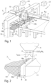
- Fig. 1 shows an exemplary structure of a machine 1 for laser processing, more precisely for laser cutting, a plate-shaped workpiece 2 (shown in dashed lines) using a laser beam 3.
- a plate-shaped workpiece 2 shown in dashed lines
- another type of thermal processing beam can also be used instead of the laser beam 3.
- the workpiece 2 rests on two workpiece support surfaces 4, 5, which in the example shown form the upper sides of two workpiece tables and define a support plane E (XY plane of an XYZ coordinate system) for supporting the workpiece 2.
- E XY plane of an XYZ coordinate system
- the workpiece 2 can be moved in a controlled manner on the workpiece support surfaces 4, 5 in a first movement direction X (hereinafter: X-direction) and moved to a predetermined workpiece position Xw.
- a gap 6 is formed between the two workpiece support surfaces 4, 5, which extends in a second direction (hereinafter: Y-direction) over the entire travel path of a processing head in the form of a laser cutting head 9, which aligns and focuses the laser beam 3 onto the workpiece 2.
- the laser cutting head 9 can be moved in a controlled manner within the gap 6 in the Y-direction by means of a driven carriage 11, which serves as a movement device and is guided on a fixed gantry 10.
- the laser cutting head 9 can also be moved in a controlled manner within the gap 6 in the X-direction and can be moved in a controlled manner in the X-direction with the aid of an additional movement device 12, for example in the form of a linear drive, attached to the carriage 11.
- the laser cutting head 9 can be positioned both in the X direction and in the Y direction at a desired cutting head position Xs, Ys within the gap 6.
- Two support carriages 13a, 13b are arranged within the gap 6, each extending across the entire width b of the gap 6 and being controlled and independently movable in the Y direction within the gap 6.
- the laser cutting head 9 can be moved along a third movement direction Z (direction of gravity, hereinafter: Z-direction) by means of a further movement device 13, which is based on the first movement device in the form of the carriage 11, in order to adjust the distance between a processing nozzle 9a of the laser cutting head 9 and the surface of the workpiece 2 or to position the laser cutting head 9 at a desired cutting head position Zs or at a desired distance in the Z-direction relative to the workpiece support plane E.
- Z-direction direction of gravity
- the support carriages 13a, 13b can each be moved in the gap 6 to a desired position Y UA , Y UB in the Y direction in order to support the workpiece 2, or more precisely, the workpiece parts 17 to be cut free from the workpiece 2 or cut during machining, by means of a support surface 14a, 14b attached to the respective support carriage 13a, 13b.
- the support surface 14a, 14b of a respective support carriage 13a, 13b is flush with the workpiece support surfaces 4, 5 in the Z direction, i.e., the support surfaces 14a, 14b are located in the support plane E for the workpiece 2.
- the machine 1 has a control device 15 which serves to coordinate the movements of the workpiece 2, the laser cutting head 9 and the support carriages 13a, 13b in order to set a desired workpiece position Xw, a desired cutting head position Xs, Ys, Zs and a desired position Y UA , Y UB of the support carriages 13a, 13b in order to enable the cutting of a predetermined cutting contour 18a and, if necessary, to support the workpiece in the region of the gap 6.
- the movement of the first support carriage 13a can take place synchronously with or independently of the second support carriage 13b.
- the control device 15 also serves to control a beam source 31 in the form of a laser source.
- a covering element 16a, 16b is attached to each of the outer edges of the support surfaces 14a, 14b, which extend in the X direction and face away from one another, to cover the gap 6 outside the cutting area formed between the support carriages 13a, 13b.
- the covering elements 16a, 16b extend over the entire width b of the gap 6 and are moved along with the movement of the support carriages 13a, 13b in the Y direction.
- the last connection between the workpiece part 17 and the residual skeleton 19 is severed at a free-cutting position FP.
- the two Support carriages 13a, 13b are moved closer together so that only a very small distance or no distance remains between them in the Y direction.
- Fig. 2 shows a detail of workpiece 2 of Fig. 1 in a sectional view showing a cutting gap 26 with a cutting gap width B, which is formed along the specified cutting contour 18a in the workpiece 2.
- the cutting gap width B of the cutting gap 26 is determined by process parameters such as cutting gas pressure, feed rate, laser power, etc. If the Fig. 1 If the cutting operation shown is carried out correctly, the workpiece part 17 is completely separated from the remaining part 19 at the free-cutting position FP along the predetermined cutting contour 18a.
- the workpiece part 17 is then removed from the workpiece plane E, for example by the two support carriages 13a, 13b being moved in opposite directions in the gap 6, so that the workpiece part 17 is no longer supported and falls downwards into the gap 6, where the workpiece part 17 can be ejected from the machine 1 by means not described in more detail.
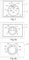
- Fig. 3 shows a plan view of the workpiece 2 with a workpiece part 17 separated from the (remaining) workpiece 2, from which, unlike in Fig. 1 shown, a circular remaining part 19 is cut out, for example, to form an opening in the workpiece part 17 for fastening a screw or the like.
- the cutting contour 18a is circular, but it is understood that the geometry of the cutting contour 18a can basically be arbitrary.
- a piercing point 20a and a linear approach contour 20b which serve for piercing and approaching the laser beam 3 before it separates the remaining part 19 from the workpiece part 17 along the predetermined cutting contour 18a.
- the machining direction 23a of the predetermined cutting contour 18a runs in Fig. 3 for example clockwise.
- the laser cutting head 9 is positioned with the aid of the two movement devices 11, 12 and/or the workpiece 2 with the aid of the movement and holding device 7 in such a way that the laser beam 3 used for processing is aligned substantially perpendicular to the surface of the workpiece 2 and radiates onto the remaining part 19 at a test position, wherein Fig. 3 Two possible test positions 21a, 21b are shown as examples. If a part that has not been completely removed is located at the test position 21a, 21b, for example the part in Fig. 3 shown residual part 19, the laser beam 3 interacts with the residual part 19, thereby generating radiation 27 which is Fig. 3 is indicated as an example for the first test position 21a.
- the two in Fig. 3 The test positions 21a, 21b shown are located at a distance A1 from the approach contour 20b that corresponds at least to the cutting gap width B. Likewise, the test positions 21a, 21b are at a distance A2 of at least 1 mm from the specified cutting contour 18a, which corresponds at least to the cutting gap width B, in order to prevent falsification of the measurement result due to the radiation of a part of the laser beam 3 into the cutting gap 26 or into the approach contour 20b. For the rapid execution of the test step, it is advantageous if the respective test position 21a, 21b is not too far away from the free-cutting position FP.
- the two test positions 21a, 21b should also be arranged at a distance from one another that corresponds at least to the cutting gap width B.
- the pulse effect radius should be taken into account when determining the respective distance A1, A2, typically by increasing the respective distance A1, A2 by the pulse effect radius.
- An evaluation device 28 uses the detected radiation 27 to check whether the part 17, 19 has fallen downwards out of the workpiece plane E. For the test, for example, the intensity of the detected radiation 27 can be compared with an intensity threshold. If the intensity of the detected radiation 27 is below the intensity threshold, it is assumed that the part 17, 19 has fallen downwards out of the workpiece plane E, so that practically no interaction occurs between the laser beam 3 and the part 17, 19 at the test position 21a, 21b.
- a new cutting operation can be performed immediately, as described in more detail below. If necessary, before the new cutting operation, it can be checked again whether the workpiece part 17 has been completely separated from the remaining part 19, i.e., the test step can be repeated in the manner described above, usually with a different test position. In this case, the new cutting operation is only performed if both test steps show that the workpiece part 17 has not been completely separated from the remaining part 19.
- the renewed cutting machining is carried out along a further cutting contour 18b, which is offset laterally to the predetermined cutting contour 18a, in the examples shown by a constant amount V in the direction of the remaining part 19.
- the Fig. 4a and in Fig. 4b The examples shown differ in that Fig. 4a as in Fig. 3 the remaining part 19 is circular, while in Fig. 4b the good part 17 is circular and is cut out of the remaining part 19, which in this case forms the residual skeleton of the workpiece 2.
- the test position(s) 21a, 21b are also selected within the closed cutting contour 18a, ie within the circular good part 17.
- the further cutting contour 18b is offset radially inwards in the direction of the remaining part 19, while in the Fig. 4b shown example, the further cutting contour 18b is offset radially outwards in the direction of the residual skeleton 19.
- the amount V of the offset of the further cutting contour 18b is selected such that the processing beam 3 striking the workpiece 2 for cutting the further cutting contour 18b does not touch the edge 25 of the workpiece part 17 (good part) or only touches it at the outer edge of the Fig. 2 shown distribution of intensity I (Gaussian profile), so that the edge 25 of the workpiece part 17 is not damaged by the laser beam 3 during further cutting.
- the amount V of the lateral offset can be selected such that the laser beam 3, during cutting along the further cutting contour 18b, hits the edge 25 of the workpiece part with an intensity I that is less than 50%, preferably less than 30%, in particular less than 20% of the maximum intensity I MAX (cf. Fig. 2 ) of the beam profile of the laser beam 3, which is radially symmetric to the Fig. 2 indicated beam axis of the laser beam 3.
- the amount V of the lateral offset can in particular be more than approximately 2% or more than 5% of the cutting gap width B of the specified cutting contour 18a.
- the amount V of the offset is typically selected such that it is less than the cutting gap width B of the cutting gap 26 along the predetermined cutting contour 18a. It is understood that, unlike in Fig. 4a ,b the amount of the offset V is not necessarily constant, but rather can change along the further cutting contour 18b. As in Fig. 4a ,b, the further cutting contour 18b can be traversed in the opposite processing direction 23b to the specified cutting contour 18a, but it is also possible that the processing direction of the specified cutting contour 18a and the further cutting contour 18b correspond, so that both cutting contours 18a, 18b are cut clockwise.
- the further cutting contour 18b may also not be absolutely necessary for the further cutting contour 18b to extend over the entire length of the predetermined cutting contour 18a, rather the further cutting contour 18b can only extend along a section 29 of the predetermined cutting contour 18a, as shown in Fig. 4b is shown.
- a cutting gas jet 33 is used for cutting along the predetermined cutting contour 18a, which jet exits through the processing nozzle 9a of the laser cutting head 9 in the direction of the workpiece 2.
- the processing process is a flame cutting process, ie the cutting gas jet 33 consists of a reactive gas or the cutting gas jet 33 contains a reactive gas, in the example shown oxygen O 2 .
- the cutting gas jet 33 is also used for further cutting along the further, laterally offset cutting contour 18b, although in this case an inert cutting gas in the form of nitrogen N 2 is used.
- an inert cutting gas for the further cutting along the further cutting contour 18b has proven to be advantageous because, on the one hand, a higher gas pressure can be used than is the case with a reactive gas and, on the other hand, the use of the inert cutting gas N 2 reduces the risk of a thermal reaction with the workpiece material.
- a further test can be carried out to determine whether the workpiece part 17 has been completely separated from the remaining part 19.
- the renewed test can be carried out in the manner described above, but it is also possible to carry out the test and, if necessary, the renewed test using a different sensor system, e.g. in the form of a light barrier arranged below the workpiece plane E and which detects a fall of the part 17, 19. If the renewed test shows that the part 17, 19 has not been completely cut free, a further cutting process can be carried out, followed by a further test step. It is understood that, to avoid an endless loop, an abort criterion should be provided so that the machine 1 pauses after a predetermined number of repetitions of the cutting process and the test.
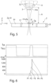
- Fig. 5 shows the beam profile of the laser beam 3, which is focused onto the workpiece 2 by a focusing device 32 (focusing lens) arranged in the processing head 9.
- the workpiece 2 is made of steel, for example structural steel or stainless steel.
- the cross-sectional area of the laser beam 3 on the underside of the workpiece 2 is larger by a factor of 37 compared to the cross-sectional area of the laser beam 3 on the top side, i.e., in the example shown, at the focus position Z F.
- the cross-sectional area of the laser beam 3 is increased by this factor and the intensity I P of the laser beam that strikes the workpiece part 17 is correspondingly reduced by a factor of 1/37.
- the laser beam 3 is irradiated onto the workpiece 2 with a comparatively low power P, there is a risk that a workpiece part 17 which has sunk downwards but is still connected to the remaining part 19 will not be detected due to the insufficient interaction of the laser beam 3 with the workpiece part 17 and that it will not be detected when the process is continued This results in collisions with the sagging workpiece part 17.
- the laser beam 3 is irradiated onto the workpiece 2 with a comparatively high power P, a scratch may be burned into a workpiece part 17 located at the height of the top of the workpiece 2, which is generally accompanied by massive sparking. The sparking may lead to contamination of the machine, for example, by the generation of splashes on a protective glass provided on the processing head 9.
- the laser beam 3 may also pierce the workpiece 2.
- Piercing the workpiece 2 or the workpiece part 17 means that after repeated cutting—at least at the same test position 21a—a valid test cannot be performed again, since such a test may no longer result in any interaction with the material of the workpiece part 17, even if it is still connected to the remaining part 19. In this case, too, there is a risk that a workpiece part 17 still connected to the remaining part 19 will not be detected, which could lead to unwanted collisions when the process continues.
- a constant power P of the laser beam 3 If a constant power P of the laser beam 3 is used for the test, it must, on the one hand, be large enough that a workpiece part that has sunk close to the underside of the workpiece 2 can just be detected, and, on the other hand, the power P must not be so large that a crater is burned into a workpiece part 17 located on the upper side of the workpiece 2. For a comparatively thick workpiece 2, these conditions cannot usually be met with one and the same power P of the laser beam 3.
- the power P of the pulsed laser beam 3 shown in the example is increased stepwise during the test, as shown by way of example in Fig. 6 shown below.
- Fig. 6 is the power P, or more precisely the average power, of the pulsed laser beam 3 for five consecutive pulses P1 to P5.
- the average power of the pulses P1 to P5 of the laser beam 3 is shown in the example shown during the gradual increase each doubled, ie the first pulse P1 has an average power of 100 W, the second pulse P2 has an average power of 200 W, the third pulse P3 has an average power of 400 W, the fourth pulse P4 has an average power of 800 W and the fifth pulse P5 has an average power of 1600 W.
- the duration of a respective pulse P1 to P5 or a respective stage can be in the order of a few milliseconds, so that the entire Fig. 6 shown pulse sequence and thus the total test duration is not more than, for example, approx. 20 ms.
- the intensity I IR of the detected radiation 27 is detected by the detector 22.
- the intensity I IR of the detected radiation 27 is continuously compared with an intensity threshold value I IR,S during the test, as shown in Fig. 6 shown above.
- the control device 15 acts on the beam source 31 via a real-time interface to switch off the laser beam 3.
- a continuous increase in the power P of the laser beam can also take place.
- a continuous laser beam 3 can also be used, the power of which can be type of ramp or the like during the test period up to a maximum power.
- the intensity Ip at test position 21a can also be increased by continuously or stepwise changing, typically reducing, the distance A between processing head 9 and workpiece 2 during the irradiation of laser beam 3.
- processing head 9 is positioned, for example, at a distance A from workpiece 2 at which focus position Z F is above the top side of workpiece 2.
- the distance A between processing head 9 and workpiece 2 is subsequently reduced until focus position Z F is at the top side of workpiece 2, at a position between the top side and the bottom side of workpiece 2, or at the bottom side of the workpiece.
- the irradiation of the laser beam 3 onto the test position 21a is terminated as soon as the intensity threshold value I IR,S is exceeded in order to avoid excessive interaction with the workpiece 2, which could lead to crater formation or possibly to piercing of the workpiece 2.
- the robustness against fluctuations in the nature of the material surface of the workpiece 2 and against the adjustment of the focus position relative to the workpiece 2 can also be increased.
- the distance A between the laser cutting head 9 and the workpiece 2 can be increased during subsequent cutting operations in order to increase the robustness and process reliability of the cutting process. This has proven particularly advantageous for cutting processes using a bypass nozzle, where the distance A between the The distance between the laser cutting head 9 or the nozzle 9a and the workpiece 2 is very small and can, for example, be only approximately 0.4 mm. For subsequent cutting, the distance A can be increased to 3 mm, for example.
- the focus position ZF is shifted towards the workpiece 2 when the distance A is increased.
- the focusing device in the form of the focusing lens 32 in the laser cutting head 9 can be moved, as shown in Fig. 5 indicated by a double arrow. This ensures that the subsequent cutting operation is carried out with essentially the same cutting gap width B as the cutting operation.
Landscapes
- Engineering & Computer Science (AREA)
- Physics & Mathematics (AREA)
- Optics & Photonics (AREA)
- Mechanical Engineering (AREA)
- Plasma & Fusion (AREA)
- Life Sciences & Earth Sciences (AREA)
- Forests & Forestry (AREA)
- General Health & Medical Sciences (AREA)
- Chemical & Material Sciences (AREA)
- Analytical Chemistry (AREA)
- Biochemistry (AREA)
- General Physics & Mathematics (AREA)
- Immunology (AREA)
- Pathology (AREA)
- Health & Medical Sciences (AREA)
- Computer Vision & Pattern Recognition (AREA)
- Signal Processing (AREA)
- Laser Beam Processing (AREA)
- Processing Of Stones Or Stones Resemblance Materials (AREA)
Applications Claiming Priority (3)
| Application Number | Priority Date | Filing Date | Title |
|---|---|---|---|
| DE102016220459.9A DE102016220459B3 (de) | 2016-10-19 | 2016-10-19 | Verfahren und Maschine zum schneidenden Bearbeiten eines Werkstücks |
| EP17784946.0A EP3528992B1 (fr) | 2016-10-19 | 2017-10-17 | Procédé et machine de découpe de pièces |
| PCT/EP2017/076426 WO2018073215A2 (fr) | 2016-10-19 | 2017-10-17 | Procédé et dispositif pour usiner une pièce par enlèvement de copeaux |
Related Parent Applications (1)
| Application Number | Title | Priority Date | Filing Date |
|---|---|---|---|
| EP17784946.0A Division EP3528992B1 (fr) | 2016-10-19 | 2017-10-17 | Procédé et machine de découpe de pièces |
Publications (2)
| Publication Number | Publication Date |
|---|---|
| EP4559614A2 true EP4559614A2 (fr) | 2025-05-28 |
| EP4559614A3 EP4559614A3 (fr) | 2025-08-20 |
Family
ID=60120052
Family Applications (3)
| Application Number | Title | Priority Date | Filing Date |
|---|---|---|---|
| EP17784946.0A Active EP3528992B1 (fr) | 2016-10-19 | 2017-10-17 | Procédé et machine de découpe de pièces |
| EP19207676.8A Active EP3636379B1 (fr) | 2016-10-19 | 2017-10-17 | Procédé et machine de découpe de pièces |
| EP25169318.0A Pending EP4559614A3 (fr) | 2016-10-19 | 2017-10-17 | Procédé et machine pour l'usinage par découpe d'une pièce |
Family Applications Before (2)
| Application Number | Title | Priority Date | Filing Date |
|---|---|---|---|
| EP17784946.0A Active EP3528992B1 (fr) | 2016-10-19 | 2017-10-17 | Procédé et machine de découpe de pièces |
| EP19207676.8A Active EP3636379B1 (fr) | 2016-10-19 | 2017-10-17 | Procédé et machine de découpe de pièces |
Country Status (6)
| Country | Link |
|---|---|
| US (2) | US10843296B2 (fr) |
| EP (3) | EP3528992B1 (fr) |
| CN (2) | CN114012246B (fr) |
| DE (1) | DE102016220459B3 (fr) |
| PL (1) | PL3636379T3 (fr) |
| WO (1) | WO2018073215A2 (fr) |
Families Citing this family (15)
| Publication number | Priority date | Publication date | Assignee | Title |
|---|---|---|---|---|
| DE102016111455B4 (de) * | 2016-06-22 | 2019-07-25 | Trumpf Laser- Und Systemtechnik Gmbh | Verfahren zur Bestimmung einer Referenz-Fokuslage sowie Werkzeugmaschine |
| DE102016220459B3 (de) | 2016-10-19 | 2018-03-29 | Trumpf Werkzeugmaschinen Gmbh + Co. Kg | Verfahren und Maschine zum schneidenden Bearbeiten eines Werkstücks |
| JP6758441B2 (ja) * | 2019-02-18 | 2020-09-23 | 株式会社アマダ | レーザ加工機、レーザ加工方法、及び加工プログラム作成装置 |
| JP6837092B2 (ja) * | 2019-05-07 | 2021-03-03 | 株式会社アマダ | レーザ加工ヘッド及びレーザ加工装置 |
| DE102019116735A1 (de) * | 2019-06-20 | 2020-12-24 | Jenoptik Automatisierungstechnik Gmbh | Verfahren zur Kontrolle und Nacharbeitung eines Werkstückes mit einer lasergeschnittenen geschlossenen Innenkontur |
| CN111014981B (zh) * | 2019-12-26 | 2021-07-20 | 中山市品尚激光科技有限公司 | 一种激光设备的加工走法 |
| DE102020205680A1 (de) * | 2020-05-06 | 2021-11-11 | Trumpf Werkzeugmaschinen Gmbh + Co. Kg | Verfahren zum Bestimmen einer minimalen Breite sowie einer Ansatzposition eines Microjoints und Verfahren zum Bearbeiten eines Werkstücks |
| JP7367861B2 (ja) * | 2020-05-08 | 2023-10-24 | 村田機械株式会社 | レーザ加工機、レーザ加工方法及び制御プログラム生成装置 |
| DE102020116626A1 (de) * | 2020-06-24 | 2021-12-30 | Trumpf Werkzeugmaschinen Gmbh + Co. Kg | Verfahren zur Entnahme eines Werkstückteils in einer Bearbeitungsmaschine, Datenverarbeitungsprogramm, Sicherungseinrichtung sowie Bearbeitungsmaschine |
| CN113111488B (zh) * | 2021-03-10 | 2022-08-09 | 东风柳州汽车有限公司 | 一种机器人激光切割参数虚拟调试方法、装置及存储介质 |
| DE102021116899A1 (de) * | 2021-06-30 | 2023-01-05 | Messer Cutting Systems Gmbh | Verfahren zur thermischen Bearbeitung eines Werkstücks mit einer thermischen Bearbeitungsmaschine |
| DE102021125781A1 (de) | 2021-10-05 | 2023-04-06 | Trumpf Werkzeugmaschinen Gmbh + Co. Kg | Laserschneidverfahren und Laserschneidmaschine |
| CN114654105A (zh) * | 2022-02-16 | 2022-06-24 | 上海柏楚电子科技股份有限公司 | 控制激光切割状态的方法、装置、系统、设备与介质 |
| EP4292751A1 (fr) * | 2022-06-15 | 2023-12-20 | Bystronic Laser AG | Machine à traiter au laser, en particulier machine de découpe au laser, dotée d'un dispositif de protection contre les étincelles |
| US12097644B1 (en) * | 2023-11-08 | 2024-09-24 | Thermwood Corporation | Method and system for creating additive parts |
Citations (3)
| Publication number | Priority date | Publication date | Assignee | Title |
|---|---|---|---|---|
| DE102009049750A1 (de) | 2009-10-17 | 2011-04-21 | Bayerische Motoren Werke Aktiengesellschaft | Verfahren und Vorrichtung zum Schneiden von Material mittels eines modulierten Laserstrahls |
| DE102011004117A1 (de) | 2011-02-15 | 2012-08-16 | Trumpf Laser- Und Systemtechnik Gmbh | Verfahren zur Kontrolle einer schneidenden Bearbeitung an einem Werkstück |
| WO2015080179A1 (fr) | 2013-11-27 | 2015-06-04 | 株式会社アマダホールディングス | Procédé et dispositif de découpe laser et dispositif de programmation automatique |
Family Cites Families (19)
| Publication number | Priority date | Publication date | Assignee | Title |
|---|---|---|---|---|
| DE3926859A1 (de) * | 1988-12-30 | 1990-07-05 | Fraunhofer Ges Forschung | Verfahren und vorrichtung zum bearbeiten von werkstuecken mit laserstrahlung |
| DE69114399T2 (de) * | 1990-08-07 | 1996-03-21 | Amada Co | Vorrichtung zum Ermitteln des Schneidzustands bei der Laserstrahlbearbeitung. |
| JP4694795B2 (ja) * | 2004-05-18 | 2011-06-08 | 株式会社ディスコ | ウエーハの分割方法 |
| WO2006132229A1 (fr) * | 2005-06-07 | 2006-12-14 | Nissan Tanaka Corporation | Procédé de perçage au laser et matériel d’usinage |
| DE102007027987B3 (de) | 2007-06-14 | 2008-10-30 | Trumpf Werkzeugmaschinen Gmbh + Co. Kg | Vorrichtung zur Aufnahme von plattenförmigen Materialien für zumindest einen Trennvorgang |
| DE102007047298B3 (de) * | 2007-10-02 | 2009-04-09 | Trumpf Werkzeugmaschinen Gmbh + Co. Kg | Verfahren zur Fokuslagenbestimmung und Laserbearbeitungsdüse |
| DE102007059987B4 (de) * | 2007-12-11 | 2015-03-05 | Trumpf Werkzeugmaschinen Gmbh + Co. Kg | Verfahren zum keyhole-freien Laserschmelzschneiden mittels vor- und nachlaufender Laserstrahlen |
| DE102008053729C5 (de) * | 2008-10-29 | 2013-03-07 | Trumpf Werkzeugmaschinen Gmbh + Co. Kg | Laserbearbeitungsdüse zum Bearbeiten von Blechen |
| US8680429B2 (en) * | 2009-11-10 | 2014-03-25 | Instrument Associates LLC | Laser beam scribing system |
| CN102510788B (zh) * | 2010-06-14 | 2014-12-24 | 三菱电机株式会社 | 激光加工装置以及激光加工方法 |
| DE202010017944U1 (de) | 2010-08-19 | 2013-03-26 | Trumpf Werkzeugmaschinen Gmbh + Co. Kg | Werkzeugmaschine zum schneidenden Bearbeiten von Werkstücken |
| DE102011078276C5 (de) | 2011-06-29 | 2014-04-03 | Trumpf Laser- Und Systemtechnik Gmbh | Verfahren zum Erkennen von Fehlern während eines Laser-Bearbeitungsprozesses sowie Laser-Bearbeitungsvorrichtung |
| DE102012100721B3 (de) * | 2012-01-30 | 2013-04-11 | Trumpf Werkzeugmaschinen Gmbh + Co. Kg | Verfahren zum Regeln eines Laserschneidprozesses und Laserschneidmaschine |
| CN104107982A (zh) * | 2013-04-19 | 2014-10-22 | 鸿富锦精密工业(深圳)有限公司 | 切割设备及切割方法 |
| DE102013209526B4 (de) * | 2013-05-23 | 2015-04-30 | Trumpf Werkzeugmaschinen Gmbh + Co. Kg | Verfahren, Computerprogrammprodukt und Vorrichtung zum Erkennen eines Schnittabrisses |
| DE102013210844B3 (de) * | 2013-06-11 | 2014-09-25 | Trumpf Werkzeugmaschinen Gmbh + Co. Kg | Verfahren zum Bilden eines Durchgangslochs in einem metallischen Werkstück, Laserbearbeitungsmaschine und Computerprogrammprodukt |
| DE102013010200B4 (de) * | 2013-06-13 | 2025-11-27 | Novanta Europe Gmbh | Verfahren zum Auffinden der optimalen Fokuslage zum Laser-Abtragen und -Schneiden mit minimaler Schnittbreite und guter Kantenqualität |
| US10086476B2 (en) * | 2013-11-28 | 2018-10-02 | Amada Holdings Co., Ltd. | Laser processing method and laser processing machine |
| DE102016220459B3 (de) | 2016-10-19 | 2018-03-29 | Trumpf Werkzeugmaschinen Gmbh + Co. Kg | Verfahren und Maschine zum schneidenden Bearbeiten eines Werkstücks |
-
2016
- 2016-10-19 DE DE102016220459.9A patent/DE102016220459B3/de active Active
-
2017
- 2017-10-17 EP EP17784946.0A patent/EP3528992B1/fr active Active
- 2017-10-17 CN CN202111411460.XA patent/CN114012246B/zh active Active
- 2017-10-17 EP EP19207676.8A patent/EP3636379B1/fr active Active
- 2017-10-17 PL PL19207676T patent/PL3636379T3/pl unknown
- 2017-10-17 CN CN201780065042.5A patent/CN109862990B/zh active Active
- 2017-10-17 EP EP25169318.0A patent/EP4559614A3/fr active Pending
- 2017-10-17 WO PCT/EP2017/076426 patent/WO2018073215A2/fr not_active Ceased
-
2019
- 2019-04-18 US US16/387,848 patent/US10843296B2/en active Active
-
2020
- 2020-11-20 US US16/953,496 patent/US11420292B2/en active Active
Patent Citations (3)
| Publication number | Priority date | Publication date | Assignee | Title |
|---|---|---|---|---|
| DE102009049750A1 (de) | 2009-10-17 | 2011-04-21 | Bayerische Motoren Werke Aktiengesellschaft | Verfahren und Vorrichtung zum Schneiden von Material mittels eines modulierten Laserstrahls |
| DE102011004117A1 (de) | 2011-02-15 | 2012-08-16 | Trumpf Laser- Und Systemtechnik Gmbh | Verfahren zur Kontrolle einer schneidenden Bearbeitung an einem Werkstück |
| WO2015080179A1 (fr) | 2013-11-27 | 2015-06-04 | 株式会社アマダホールディングス | Procédé et dispositif de découpe laser et dispositif de programmation automatique |
Also Published As
| Publication number | Publication date |
|---|---|
| CN109862990A (zh) | 2019-06-07 |
| EP3636379B1 (fr) | 2021-03-10 |
| US20210078110A1 (en) | 2021-03-18 |
| EP3636379A1 (fr) | 2020-04-15 |
| EP4559614A3 (fr) | 2025-08-20 |
| US11420292B2 (en) | 2022-08-23 |
| EP3528992A2 (fr) | 2019-08-28 |
| CN109862990B (zh) | 2021-12-14 |
| CN114012246B (zh) | 2025-10-28 |
| DE102016220459B3 (de) | 2018-03-29 |
| EP3528992B1 (fr) | 2025-04-30 |
| WO2018073215A2 (fr) | 2018-04-26 |
| US10843296B2 (en) | 2020-11-24 |
| WO2018073215A3 (fr) | 2018-07-19 |
| PL3636379T3 (pl) | 2021-09-27 |
| CN114012246A (zh) | 2022-02-08 |
| US20190247960A1 (en) | 2019-08-15 |
Similar Documents
| Publication | Publication Date | Title |
|---|---|---|
| EP3528992B1 (fr) | Procédé et machine de découpe de pièces | |
| DE112014006885B4 (de) | Laserbearbeitungsverfahren und Laserbearbeitungsvorrichtung | |
| EP2908981B1 (fr) | Méthode et machine d'usinage pour rainurer, percer ou découper des pièces métalliques, avec détermination de l'intensité de la radiation d'usinage | |
| DE3926859C2 (fr) | ||
| EP3007852B1 (fr) | Procédé de rainurage dans des composants métalliques en utilisant un faisceau laser | |
| DE102012100721B3 (de) | Verfahren zum Regeln eines Laserschneidprozesses und Laserschneidmaschine | |
| EP3475025B1 (fr) | Procédé et dispositif pour déterminer une position de point focal de référence d'un faisceau d'une machine-outil à faisceau par exécution d'une séquence de découpes d'essai sur une pièce à usiner | |
| EP3159093B1 (fr) | Methode de controle d'un procede de decoupe au laser de haute energie avec interruption du procede de decoupage ; dispositif et programme d'ordinateur correspondants | |
| EP2675588B1 (fr) | Méthode de contrôle d'une opération de découpe sur une pièce | |
| DE102013217126B4 (de) | Verfahren zum Feststellen von Abweichungen einer Ist-Lage eines Laserbearbeitungskopfes von einer Soll-Lage, Laserbearbeitungsmaschine und Computerprogrammprodukt | |
| EP3965990B1 (fr) | Procédé et dispositif de traitement au laser d'une pièce | |
| EP4035823B1 (fr) | Procédé d'usinage par faisceau d'une pièce tabulaire ou tubulaire | |
| EP4200101B1 (fr) | Procédé de production d'au moins une partie de pièce à usiner et d'une pièce à usiner résiduelle à partir d'une pièce à usiner | |
| DE102011054988B4 (de) | Lochvorrichtung und Lochverfahren | |
| EP4238687A1 (fr) | Procédé d'usinage d'une pièce à usiner en forme de plaque ou de tube | |
| EP1238749B1 (fr) | Méthode et appareil pour le découpage par chalumeau de pièces | |
| DE102017109186B4 (de) | Verfahren zum überwachten Ausschneiden eines Schneidbutzens aus einem metallischen Werkstück | |
| EP4117853B1 (fr) | Procédé et dispositif de découpe d'une pièce à usiner à l'aide d'un faisceau laser | |
| EP4031315B1 (fr) | Procédé de découpe au laser et dispositif de découpe au laser associé | |
| WO2023072568A1 (fr) | Procédé de fabrication de parties de pièces présentant des arêtes de coupe chanfreinées | |
| WO2023072567A1 (fr) | Procédé d'usinage d'une pièce par faisceau laser à énergie par unité de longueur constante du faisceau laser | |
| EP4422821A1 (fr) | Procédé de réalisation de trous chanfreinés par usinage laser | |
| EP4594045A1 (fr) | Procédé de découpe au laser de pièces en forme de plaque, et produit programme informatique associé |
Legal Events
| Date | Code | Title | Description |
|---|---|---|---|
| PUAI | Public reference made under article 153(3) epc to a published international application that has entered the european phase |
Free format text: ORIGINAL CODE: 0009012 |
|
| STAA | Information on the status of an ep patent application or granted ep patent |
Free format text: STATUS: REQUEST FOR EXAMINATION WAS MADE |
|
| 17P | Request for examination filed |
Effective date: 20250409 |
|
| AC | Divisional application: reference to earlier application |
Ref document number: 3528992 Country of ref document: EP Kind code of ref document: P |
|
| AK | Designated contracting states |
Kind code of ref document: A2 Designated state(s): AL AT BE BG CH CY CZ DE DK EE ES FI FR GB GR HR HU IE IS IT LI LT LU LV MC MK MT NL NO PL PT RO RS SE SI SK SM TR |
|
| REG | Reference to a national code |
Ref country code: DE Ref legal event code: R079 Free format text: PREVIOUS MAIN CLASS: B23K0026142000 Ipc: B23K0026030000 |
|
| PUAL | Search report despatched |
Free format text: ORIGINAL CODE: 0009013 |
|
| AK | Designated contracting states |
Kind code of ref document: A3 Designated state(s): AL AT BE BG CH CY CZ DE DK EE ES FI FR GB GR HR HU IE IS IT LI LT LU LV MC MK MT NL NO PL PT RO RS SE SI SK SM TR |
|
| RIC1 | Information provided on ipc code assigned before grant |
Ipc: B23K 26/03 20060101AFI20250716BHEP Ipc: B23K 26/38 20140101ALI20250716BHEP Ipc: G01N 21/88 20060101ALI20250716BHEP Ipc: B23K 26/142 20140101ALI20250716BHEP |