EP4557052A1 - Task scheduler device, calculation system, and task scheduling method, and program - Google Patents
Task scheduler device, calculation system, and task scheduling method, and program Download PDFInfo
- Publication number
- EP4557052A1 EP4557052A1 EP22951047.4A EP22951047A EP4557052A1 EP 4557052 A1 EP4557052 A1 EP 4557052A1 EP 22951047 A EP22951047 A EP 22951047A EP 4557052 A1 EP4557052 A1 EP 4557052A1
- Authority
- EP
- European Patent Office
- Prior art keywords
- task
- processor
- cpu
- state
- core
- Prior art date
- Legal status (The legal status is an assumption and is not a legal conclusion. Google has not performed a legal analysis and makes no representation as to the accuracy of the status listed.)
- Pending
Links
Images




Classifications
-
- G—PHYSICS
- G06—COMPUTING OR CALCULATING; COUNTING
- G06F—ELECTRIC DIGITAL DATA PROCESSING
- G06F9/00—Arrangements for program control, e.g. control units
- G06F9/06—Arrangements for program control, e.g. control units using stored programs, i.e. using an internal store of processing equipment to receive or retain programs
- G06F9/46—Multiprogramming arrangements
- G06F9/50—Allocation of resources, e.g. of the central processing unit [CPU]
- G06F9/5094—Allocation of resources, e.g. of the central processing unit [CPU] where the allocation takes into account power or heat criteria
-
- G—PHYSICS
- G06—COMPUTING OR CALCULATING; COUNTING
- G06F—ELECTRIC DIGITAL DATA PROCESSING
- G06F1/00—Details not covered by groups G06F3/00 - G06F13/00 and G06F21/00
- G06F1/26—Power supply means, e.g. regulation thereof
- G06F1/32—Means for saving power
- G06F1/3203—Power management, i.e. event-based initiation of a power-saving mode
- G06F1/3206—Monitoring of events, devices or parameters that trigger a change in power modality
- G06F1/3215—Monitoring of peripheral devices
-
- G—PHYSICS
- G06—COMPUTING OR CALCULATING; COUNTING
- G06F—ELECTRIC DIGITAL DATA PROCESSING
- G06F1/00—Details not covered by groups G06F3/00 - G06F13/00 and G06F21/00
- G06F1/26—Power supply means, e.g. regulation thereof
- G06F1/32—Means for saving power
- G06F1/3203—Power management, i.e. event-based initiation of a power-saving mode
- G06F1/3234—Power saving characterised by the action undertaken
- G06F1/324—Power saving characterised by the action undertaken by lowering clock frequency
-
- G—PHYSICS
- G06—COMPUTING OR CALCULATING; COUNTING
- G06F—ELECTRIC DIGITAL DATA PROCESSING
- G06F1/00—Details not covered by groups G06F3/00 - G06F13/00 and G06F21/00
- G06F1/26—Power supply means, e.g. regulation thereof
- G06F1/32—Means for saving power
- G06F1/3203—Power management, i.e. event-based initiation of a power-saving mode
- G06F1/3234—Power saving characterised by the action undertaken
- G06F1/3243—Power saving in microcontroller unit
-
- G—PHYSICS
- G06—COMPUTING OR CALCULATING; COUNTING
- G06F—ELECTRIC DIGITAL DATA PROCESSING
- G06F1/00—Details not covered by groups G06F3/00 - G06F13/00 and G06F21/00
- G06F1/26—Power supply means, e.g. regulation thereof
- G06F1/32—Means for saving power
- G06F1/3203—Power management, i.e. event-based initiation of a power-saving mode
- G06F1/3234—Power saving characterised by the action undertaken
- G06F1/3287—Power saving characterised by the action undertaken by switching off individual functional units in the computer system
-
- G—PHYSICS
- G06—COMPUTING OR CALCULATING; COUNTING
- G06F—ELECTRIC DIGITAL DATA PROCESSING
- G06F1/00—Details not covered by groups G06F3/00 - G06F13/00 and G06F21/00
- G06F1/26—Power supply means, e.g. regulation thereof
- G06F1/32—Means for saving power
- G06F1/3203—Power management, i.e. event-based initiation of a power-saving mode
- G06F1/3234—Power saving characterised by the action undertaken
- G06F1/329—Power saving characterised by the action undertaken by task scheduling
-
- G—PHYSICS
- G06—COMPUTING OR CALCULATING; COUNTING
- G06F—ELECTRIC DIGITAL DATA PROCESSING
- G06F1/00—Details not covered by groups G06F3/00 - G06F13/00 and G06F21/00
- G06F1/26—Power supply means, e.g. regulation thereof
- G06F1/32—Means for saving power
- G06F1/3203—Power management, i.e. event-based initiation of a power-saving mode
- G06F1/3234—Power saving characterised by the action undertaken
- G06F1/3296—Power saving characterised by the action undertaken by lowering the supply or operating voltage
-
- G—PHYSICS
- G06—COMPUTING OR CALCULATING; COUNTING
- G06F—ELECTRIC DIGITAL DATA PROCESSING
- G06F9/00—Arrangements for program control, e.g. control units
- G06F9/06—Arrangements for program control, e.g. control units using stored programs, i.e. using an internal store of processing equipment to receive or retain programs
- G06F9/46—Multiprogramming arrangements
- G06F9/48—Program initiating; Program switching, e.g. by interrupt
- G06F9/4806—Task transfer initiation or dispatching
- G06F9/4843—Task transfer initiation or dispatching by program, e.g. task dispatcher, supervisor, operating system
- G06F9/4881—Scheduling strategies for dispatcher, e.g. round robin, multi-level priority queues
- G06F9/4893—Scheduling strategies for dispatcher, e.g. round robin, multi-level priority queues taking into account power or heat criteria
-
- G—PHYSICS
- G06—COMPUTING OR CALCULATING; COUNTING
- G06F—ELECTRIC DIGITAL DATA PROCESSING
- G06F9/00—Arrangements for program control, e.g. control units
- G06F9/06—Arrangements for program control, e.g. control units using stored programs, i.e. using an internal store of processing equipment to receive or retain programs
- G06F9/46—Multiprogramming arrangements
- G06F9/50—Allocation of resources, e.g. of the central processing unit [CPU]
- G06F9/5005—Allocation of resources, e.g. of the central processing unit [CPU] to service a request
- G06F9/5027—Allocation of resources, e.g. of the central processing unit [CPU] to service a request the resource being a machine, e.g. CPUs, Servers, Terminals
- G06F9/505—Allocation of resources, e.g. of the central processing unit [CPU] to service a request the resource being a machine, e.g. CPUs, Servers, Terminals considering the load
-
- Y—GENERAL TAGGING OF NEW TECHNOLOGICAL DEVELOPMENTS; GENERAL TAGGING OF CROSS-SECTIONAL TECHNOLOGIES SPANNING OVER SEVERAL SECTIONS OF THE IPC; TECHNICAL SUBJECTS COVERED BY FORMER USPC CROSS-REFERENCE ART COLLECTIONS [XRACs] AND DIGESTS
- Y02—TECHNOLOGIES OR APPLICATIONS FOR MITIGATION OR ADAPTATION AGAINST CLIMATE CHANGE
- Y02D—CLIMATE CHANGE MITIGATION TECHNOLOGIES IN INFORMATION AND COMMUNICATION TECHNOLOGIES [ICT], I.E. INFORMATION AND COMMUNICATION TECHNOLOGIES AIMING AT THE REDUCTION OF THEIR OWN ENERGY USE
- Y02D10/00—Energy efficient computing, e.g. low power processors, power management or thermal management
Definitions
- the present invention relates to a task scheduler device, a calculation system, a task scheduling method, and a program.
- FIG. 19 is a diagram illustrating an overview of a radio access system.
- Antenna 20 is an antenna and a transmission and reception unit for performing radio communication with UE 10 (hereinafter, an "antenna" collectively refers to the antenna, the transmission and reception unit, and its power supply unit). Transmission and reception data are connected to base station 30, for example, with a dedicated cable, for example.
- Base station (BBU) 30 includes task scheduler device 34.
- Task scheduler device 34 performs task management, priority assignment, and task allocation.
- CPUidle state defines grades C0 to C6, and transitions to a deep sleep state occur as the time during which CPU 32 has no load becomes long. Although the power consumption of the CPU becomes less in a deeper sleep state, the time required until restoration is extended accordingly, which may possibly raise an issue in the perspective of low latency.
- C-state The state definition of C-state varies depending on the CPU hardware. For example, there are variations such that a model has no C4 or C5, a model has a state of C1E after C1, and the like.
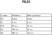
- FIG. 22 is a diagram illustrating an example of the time for transitioning to a state (RESIDENCY) and the maximum value of the time required for restoration (WAKE-UP LATENCY) in the form of a table.
- FIG. 22 illustrates C-state information in the case of Intel Xeon CPU E5-26X0 v4 (registered trademark).
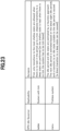
- Linux kernel 4 (registered trademark) provides two types of Governors in order to manage CPU idle states (C-states).
- FIG. 23 is a diagram illustrating the types of CPU idle Governor.
- ladder is used for a system with a tick
- menu is used for a tickless system.
- menu which is used for tickless systems, is a scheme for estimating the depth of an idle state suitable for the next idle period based on the actual record of the latest idle period.
- menu is effective for workloads in which the idle times are regular but its effect is limited for irregular workloads.
- FIG. 24 is a diagram illustrating an overview of the logic of menu.
- menu records the latest idle times. Then, as illustrated in the middle drawing in FIG. 24 , menu estimates the next idle time. For example, based on the idle times shown in the left drawing in FIG. 24 , when the deviation is small, menu adopts an average value T_avr as the next idle time. As illustrated in the right drawing in FIG. 24 , menu estimates a suitable idle state depth based on the estimation of the next idle time. For example, when the next idle time estimation value T_avr is comparable to the exit latency, the time for restoration from an idle state (Cx), menu determines that the idle state is excessively deep and causes a transition to an idle state of Cx-1.
- T_avr is comparable to the exit latency
- Cx the time for restoration from an idle state
- CPUidle state defines grades, and transitions to a deep sleep state occur as the time during which the CPU has no load becomes long. Although the power consumption of the CPU becomes less in a deeper sleep state, the time required for restoration is extended accordingly, which may possibly raise an issue in the perspective of low latency.
- FIGS. 25 and 26 are image diagrams illustrating C-state transitions of a CPU core used for operations.
- FIG. 25 illustrates a case where a time with no task is short and
- FIG. 26 illustrates a case where a time with no task is long.
- the above-mentioned issue is a problem that cannot be overlooked in a system in which real-time capability is given the highest priority, such as the base station (BBU) 30 illustrated in FIGS. 19 and 20 .
- BBU base station
- a countermeasure of applying a setting to invalidate C-states or to limit the transition of idle states to a limited depth such as C1 is adopted. That is, in some cases, tuning for prioritizing real-time capability at the expense of power saving is implemented.
- the present invention has been made in view of such a background, and an object of the present invention is to perform operations with a low latency while achieving power saving.
- a task scheduler device that, in a calculation system that reduces power consumption by reducing stepwise an operation state of a processor according to a processing load, allocates tasks to a core group of the processor, the task scheduler device including: a processor use rate acquisition part that acquires a use rate of the processor; and a task allocation part that, based on the use rate of the processor acquired by the processor use rate acquisition part, continuously allocates tasks to a core or a core group of the processor to be used at a predetermined frequency or more.
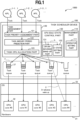
- an operation system 1000 includes hardware (HW) 31, CPU cores (CPU core #0, CPU core #1,...) 32 (processors) on the hardware 31, an OS 33, L1, L2, and L3 protocol radio signal processing applications 1-1, 1-2, and 1-3 (collectively referred to as an APL 1), and a task scheduler device 100.
- HW hardware
- CPU cores CPU core #0, CPU core #1, etc
- OS OS
- L1, L2, and L3 protocol radio signal processing applications 1-1, 1-2, and 1-3 collectively referred to as an APL 1
- Operation system 1000 is a calculation system that reduces power consumption by reducing stepwise an operation state of the processor according to a processing load.
- the processor has a plurality of core groups, and includes task scheduler device 100 that allocates tasks to a core group of the processor.
- Task scheduler device 100 includes a management part 110, a task management part 120, and a CPU idle state control part 130.
- the management part 110 includes a operator setting part 111.
- Task management part 120 includes a task priority assignment part 121, a task amount/period prediction part 122 (processor use rate acquisition part), and a task CPU allocation part 123 (task allocation part).
- Task priority assignment part 121 assigns a task priority to a task transmitted from APL 1 as necessary.
- Task management part 120 executes priority control of allocation to the CPU core according to the priority.
- the most accurate representation of the CPU state is considered to be a "CPU use rate per unit time of a CPU core being used".
- the "CPU use rate per unit time of the CPU core being used” can be substantially estimated by a task amount. How the CPU is busy can be estimated by the task amount, but it depends on how many processes the CPU is not good at, which cannot be measured by the task amount.
- the processor is a GPU, an FPGA, and an ASIC other than CPUs, processing that the processor is good at or not good at also varies.
- the task amount is used as a physical amount related to the "CPU use rate per unit time of the CPU core being used".
- Task amount/period prediction part 122 acquires the use rate of the processor. Specifically, task amount/period prediction part 122 measures a task amount per unit time and/or a CPU use rate according to a determination logic illustrated in FIG. 4 , and determines whether the number of CPU cores to be used for operations needs to be increased or decreased.
- Task amount/period prediction part 122 performs an in-advance wake-up on a CPU core to be newly used. There are many CPU products such that the C-state is restored to C0 when certain processing is executed by the CPU core. For this reason, there is a method in which the CPU core executes processing such as small operations and/or outputting a character string to a standard output.
- Task CPU allocation part 123 continuously allocates tasks to a core or a core group of a processor to be used at a predetermined frequency or more, based on the processor use rate acquired by task amount/period prediction part 122 (processor use rate acquisition part). Task CPU allocation part 123 reduces, for example, CPU cores to be used. As a method of reducing the CPU cores, a CPU core not to be used onward is determined, and no task is allocated to the CPU core onward.
- Task CPU allocation part 123 allocates an arriving task to a CPU core (allocation to the CPU core may be performed by performing a round-robin on the CPU cores being used, or the task may be allocated to a CPU core with a task queue prepared on a per-CPU core basis and having small residues), and schedules the task into the task queue prepared per-CPU core basis.
- a task with a high priority may be preferentially allocated to an free CPU core according to the assigned priority. Further, the per-CPU core task queue may be rearranged according to the priority.
- CPU idle state control part 130 includes a CPU in-advance wake-up part 131 (in-advance wake-up part) and a C-state setting part 132 (operation state setting part).
- C-state setting part 132 sets an upper limit of a core or a core group of the processor to be used at a predetermined frequency or more so that the operation state of the processor cannot be caused to transition to a deeper state. Specifically, C-state setting part 132 applies a C-state upper limit setting to a CPU core(s) to be newly used. An upper limit state is determined by being set by an operator (see sign b in FIG. 1 ).
- a C-state upper limit setting may be applied to a CPU core(s) to be newly used before allocating a task(s) to the CPU core, to restore the CPU core(s) to a shallow state.
- the C-state upper limit setting is applied in advance taking into account a time lag from the application of the C-state upper limit setting to the reflection thereof.
- C-state setting part 132 cancels the upper limit setting.
- C-state setting part 132 applies a setting to a core or a core group to which a task(s) have not been allocated by task CPU allocation part 123 (task allocation part) so that the operation state of the processor can transition to a deeper state.
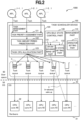
- FIGS. 2 and 3 are diagrams illustrating the deployment of task scheduler device 100 in FIG. 1 .
- FIG. 2 illustrates a configuration example in which task scheduler device 100 illustrated in FIG. 1 is deployed in a user space.
- task scheduler device 100 is deployed in a user space 60.
- Operation system 1000 executes a packet processing APL 1 deployed in the user space 60.
- Operation system 1000 executes the packet processing APL 1 on a server including an OS.
- the present invention is able to be applied to a case where there is a thread in the user space 60, such as in Intel data plane development kit (DPDK) (registered trademark).
- DPDK Intel data plane development kit
- FIG. 3 illustrates a configuration example in which task scheduler device 100 illustrated in FIG. 1 is deployed in an OS 50.
- task scheduler device 100 is deployed in OS 50.
- Operation system 1000 executes packet processing APL 1 on a server including OS 50.
- the present invention is able to be applied to a case where there is a thread inside a kernel, such as in New API (NAPI) (registered trademark) (NPL 1) and a kernel-based virtual machine (KBP).
- NAPI New API
- NPL 1 registered trademark
- KBP kernel-based virtual machine
- the present inventors have considered continuously allocating tasks to an active CPU core group and causing the other CPU cores to transition to a deep C-state to reduce power consumption.
- FIG. 4 is a diagram illustrating a required number estimation logic for an active CPU core group in the form of a table.
- determinations of the estimation logic include "1. determination based on task arrival pattern” and “2. determination based on CPU use rate”, each of which is based on threshold-based determination, periodicity, and machine learning.
- operation system 1000 configured as described above will be described below.
- a task scheduler allocating a task(s) to a CPU core(s) allocates the task(s) taking into account the C-state of the CPU core(s).
- a C-state upper limit to which a transition can be made is set for a CPU core group having a high use frequency ( FIGS. 8 to 10 ).
- a setting of C-state upper limit from which a transition to the active CPU core group is available is applied to prevent a transition to a deep C-state and reduce the restoration latency.
- the restoration time from a deep state is reduced by performing an in-advance wake-up before allocating a task to a CPU core which has transitioned to a deep state ( FIGS. 11 to 12 ).
- the restoration time from a deep C-state is reduced by performing an in-advance wake-up before allocating a task to a CPU core to be newly used (CPU core that has not been used in a while).
- Feature ⁇ 1>, Feature ⁇ 2>, and Feature ⁇ 3> will be described in order below.
- FIG. 5 is a diagram illustrating a task amount threshold-based determination and a CPU use rate threshold-based determination operation of task scheduler device 100.
- Task management part 120 performs a task amount threshold-based determination operation.
- task priority assignment part 121 assigns priorities of tasks as necessary.
- Task amount/period prediction part 122 measures a task amount per unit time and a CPU use rate according to the determination logic illustrated in FIG. 4 to determine whether the number of CPU cores to be used for operations needs to be increased or decreased.
- FIG. 6 is a diagram illustrating an image of threshold-based determination based on a task inflow amount.
- Task management part 120 manages the CPU cores based on the task inflow amount illustrated in FIG. 6 .
- a task inflow amount: W_input per unit time is correspondingly associated with the number of CPU cores to be used. For example, when W_input is "dd to ee", the number of CPU cores to be used is "4", and the active CPU core group (see a dashed box a in FIG. 5 ) is "4".
- task CPU allocation part 123 allocates an arriving task to a CPU core and schedules the task to the task queue prepared on a per-CPU core basis. At this time, a task with a high priority is preferentially allocated to a free CPU core according to the assigned priority. Further, the per-CPU core task queue is rearranged according to the priorities.
- Task management part 120 designs, for tasks whose operation time will be completed in a fixed time, the number of CPU cores required for operations corresponding to a task inflow amount per unit time according to the threshold-based determination table illustrated in FIG. 6 . Furthermore, when the task inflow amount exceeds a threshold (threshold of W_input) in the threshold-based determination table illustrated in FIG. 6 , it is possible to determine whether the number of CPU cores to be used needs to be increased. In FIG. 6 , a state of dd ⁇ W_input ⁇ ee is occurring and four CPU cores are being used. When the task inflow amount becomes as W_input ⁇ ee, the number of CPU cores is increased from four to five.
- a threshold threshold of W_input
- Task management part 120 calculates the number of required CPU cores.
- Equation (3) does not take into account the restoration time from a C-state, it is not necessary to consider the restoration time from the C-state as long as the restoration time from the C-state can be brought close to zero as far as possible according to the present embodiment.
- Threshold_upper upper limit
- Threshold_base lower limit
- task management part 120 When the average CPU use rate exceeds the upper limit, task management part 120 ( FIG. 5 ) increases the number of CPU cores to be used. In addition, when the average CPU use rate falls below the lower limit, task management part 120 reduces the number of CPU cores to be used.
- FIG. 8 is a diagram illustrating C-state upper limit setting by task scheduler device 100.
- C-state setting part 132 of CPU idle state control part 130 sets (see sign b in FIG. 8 ), to a CPU core group with a high use frequency, a C-state upper limit to which a transition can be made.
- an upper limit of CPU idle state (see, for example, C1 and C1E in FIG. 22 ) to which a transition can be made is determined, and a setting is applied such that a transition to a state deeper than that state cannot be made. This makes it possible to perform restoration from a shallow state at the time of task allocation thereby to reduce the restoration latency time.
- C-state setting part 132 dynamically sets the upper limit of CPU idle state by using the determination logic illustrated in FIG. 4 .
- a C-state upper limit setting may be applied to the CPU cores newly increased to restore the CPU cores to a shallow C-state before allocating tasks to the CPU cores.
- FIG. 9 is a diagram illustrating an image of C-state upper limit setting.
- the upper drawing in FIG. 9 illustrates a case where a C-state upper limit setting is not applied and the lower drawing in FIG. 9 illustrates a case where a C-state upper limit setting is applied.
- a C-state upper limit setting is applied (see sign g in FIG. 9 ) to a CPU core group with a high use frequency to prevent transitions to a deep state, to reduce the restoration latency time at the time of restoring from a shallow state.
- FIG. 10 is a diagram illustrating pooling highly-likely-to-be-used CPU cores by task scheduler device 100.
- a CPU core group (dashed box h in FIG. 10 ) which is set to fall only to a shallow idle state may be prepared.
- CPU cores CPU core #4, CPU core #5) 32 illustrated in FIG. 10 are pooled as a CPU core group capable of transitioning only up to C1.
- a configuration is adopted in which a CPU core group set to fall only to a shallow idle state is prepared (for example, a CPU core group capable of transitioning only up to C1 is pooled).
- FIG. 11 is a diagram illustrating an in-advance wake-up by task scheduler device 100.
- CPU in-advance wake-up part 131 When using a CPU core having fallen to a deep CPU idle state (C-state), CPU in-advance wake-up part 131 causes the CPU core to wake up in advance (see sign c in FIG. 11 ).
- FIG. 12 is a diagram illustrating an in-advance wake-up by task scheduler device 100.
- the upper drawing in FIG. 12 illustrates a case of the existing technique, and the lower drawing in FIG. 12 illustrates a case where an in-advance wake-up by task scheduler device 100 is performed.
- a CPU core with a low use frequency is caused to transition to a deep C-state to achieve a reduction in the power consumption and a reduction in the influence of the latency time due to the restoration from the deep C-state.
- FIG. 13 is a flowchart illustrating task scheduling processing by task scheduler device 100.
- step S11 APL 1 ( FIG. 1 ) registers a task in task management part 120 ( FIG. 1 ).
- step S12 task priority assignment part 121 ( FIG. 1 ) assigns a priority to the task as necessary.
- Task CPU allocation part 123 ( FIG. 1 ) executes priority control of allocation to a CPU core according to the priority.
- step S13 task amount/period prediction part 122 ( FIG. 1 ) measures the task amount per unit time and the CPU use rate according to the determination logic illustrated in FIG. 4 and determines whether it is necessary to increase or decrease the number of CPU cores to be used for operation (branches after the determination are below-described step S14 and step S15).
- step S14 when it is necessary to reduce the number of CPU cores (S14: Yes), the processing proceeds to step S17, and when it is not necessary to reduce the number of CPU cores (S14: No), the processing proceeds to step S15.
- step S15 when it is necessary to increase the number of CPU cores (S15: Yes), the processing proceeds to step S19, and when it is not necessary to increase the number of CPU cores (S15: No), the processing proceeds to step S16.
- step S16 task CPU allocation part 123 ( FIG. 1 ) allocates the arriving task to a CPU core, schedules the task to a task queue prepared on a per-CPU core basis, and finishes the processing of this flow.
- the allocation to the CPU core may be performed by performing a round-robin on the CPU cores being used, or the task may be allocated to a CPU core with a task queue prepared on a per-CPU core basis and having small residues.
- task CPU allocation part 123 may preferentially allocate a task with a high priority to a free CPU core according to the assigned priority, or may rearrange the per-CPU core task queue according to the priority.
- step S17 when it is necessary to reduce the number of CPU cores, in step S17, task CPU allocation part 123 ( FIG. 1 ) reduces the number of CPU cores to be used. For example, as a method of reducing the number of CPU cores, a CPU core not to be used onward is determined and tasks are not allocated to the CPU core onward.
- step S18 when a C-state upper limit setting has been applied to the CPU core(s) determined not to be used, C-state setting part 132 ( FIG. 1 ) cancels the C-state upper limit setting and finishes the processing of this flow .
- step S15 when it is necessary to increase the number of CPU cores, in step S19, task amount/period prediction part 122 ( FIG. 1 ) performs an in-advance wake-up on the CPU core(s) to be newly used.
- the reason why the in-advance wake-up is performed on the CPU core(s) to be newly used is as follows. That is, there are many CPU products such that the C-state is restored to C0 when certain processing is executed by the CPU core. Considering this, lightweight processing such as a small operation and/or outputting a character string to the standard output is executed by the CPU core to restrain transitions of the CPU core to a deep C-state.
- a C-state upper limit setting may be applied to the CPU core to be newly used before a task is allocated thereto to restore the CPU core to a shallow state, as described above in ⁇ C-state upper limit setting> ( FIG. 8 ).
- the C-state upper limit setting is applied in advance taking into account a time lag from the application of the C-state upper limit setting to the reflection thereof.
- step S20 C-state setting part 132 applies a C-state upper limit setting to the CPU core(s) to be newly used and finishes the processing of this flow.
- An upper limit state is determined by being set in advance by an operator.
- the C-state upper limit setting may not necessarily be applied.
- Task scheduler devices 100 and 100A ( FIGS. 1 and 10 ) according to the embodiment are implemented by, for example, a computer 900 having a configuration as illustrated in FIG. 14 .
- FIG. 14 is a hardware configuration diagram illustrating an example of computer 900 that implements functions of task scheduler devices 100 and 100A ( FIGS. 1 and 10 ).
- Computer 900 includes a CPU 901, a ROM 902, a RAM 903, an HDD 904, a communication interface (I/F) 906, an input and output interface (I/F) 905, and a media interface (I/F) 907.
- a CPU 901 a ROM 902, a RAM 903, an HDD 904, a communication interface (I/F) 906, an input and output interface (I/F) 905, and a media interface (I/F) 907.
- CPU 901 operates based on a program stored in ROM 902 or HDD 904 and performs control of parts of task scheduler devices 100 and 100A ( FIGS. 1 and 10 ).
- ROM 902 stores a boot program to be executed by CPU 901 when computer 900 is started up, a program that relies on the hardware of computer 900, and the like.
- CPU 901 controls an input device 910 such as a mouse and a keyboard and an output device 911 such as a display via the input/output I/F 905.
- CPU 901 acquires data from input device 910 and outputs generated data to output device 911 via input/output I/F 905.
- a graphics processing unit (GPU) or the like may be used together with CPU 901 as the processor.
- HDD 904 stores a program executed by CPU 901, data used by the program, and the like.
- Communication I/F 906 receives data from another device via a communication network (for example, a network (NW) 920), outputs the data to CPU 901, and transmits data generated by CPU 901 to another device via the communication network.
- a communication network for example, a network (NW) 920
- Media I/F 907 reads a program or data stored in a recording medium 912 and outputs the program or data to CPU 901 through RAM 903.
- CPU 901 loads a program related to desired processing from recording medium 912 onto RAM 903 through media I/F 907, and executes the loaded program.
- Recording medium 912 is an optical recording medium such as a digital versatile disc (DVD) or a phase change rewritable disk (PD), a magneto-optical recording medium such as a magneto optical disk (MO), a magnetic recording medium, a conductor memory tape medium, a semiconductor memory, or the like.
- CPU 901 of computer 900 implements the functions of task scheduler device 100, 100A by executing a program loaded onto RAM 903. Further, data in RAM 903 is stored in HDD 904. CPU 901 reads a program related to target processing from recording medium 912 and executes the program. Additionally, CPU 901 may read a program related to target processing from another device via the communication network (NW 920).
- NW 920 the communication network
- the present invention is able to be applied to a configuration example in which task scheduler device 100 is deployed in the user space 60.
- the OS is not limited.
- the operation system can be applied to each of the configurations illustrated in FIGS. 15 and 16 .
- SFC Service Function Chaining
- a hypervisor environment consisting of Linux (registered trademark) and a kernel-based virtual machine (KVM) is known as a technique for forming a virtual machine.
- a Host OS an OS installed on a physical server is called a "Host OS”
- a KVM module is incorporated operates as a hypervisor in a memory area called kernel space, which is different from user spaces.
- a virtual machine operates in a user space
- a Guest OS an OS installed on a virtual machine is called a Guest OS
- HW hardware
- network devices such as Ethernet (registered trademark) card devices
- operation system 1000A includes a Host OS 80 in which a virtual machine and an external process formed outside the virtual machine can operate.
- Host OS 80 includes a kernel 81 and a driver 82.
- Operation system 1000A includes a CPU 71 of a HW 70 connected to Host OS 80, and a KVM module 91 embedded in a hypervisor (HV) 90.
- operation system 1000A includes a Guest OS 95 operating in the virtual machine.
- Guest OS 95 includes a kernel 96 and a driver 97.
- Operation system 1000A includes a task scheduler device 100 connected to Guest OS 95 and deployed in user space 60.
- FIG. 16 is a diagram illustrating an example in which an operation system 1000B is applied to an interrupt model in a server virtualization environment configured with a container.
- the same constituent parts as those in FIGS. 1 and 15 are denoted by the same reference signs.
- operation system 1000B has a container configuration in which the Guest OS 95 illustrated in FIG. 15 is replaced with a container 98.
- Container 98 has a virtual NIC (vNIC).
- a virtual server configuration system such as a container, it is possible to perform operations with low latency while achieving power saving.
- the present invention is able to be applied to a configuration example in which task scheduler device 100 is deployed in OS 50.
- the OS is not limited.
- the operation system is able to be applied to each configuration illustrated in FIGS. 17 and 18 .
- FIG. 17 is a diagram illustrating an example in which an operation system 1000C is applied to an interrupt model in a server virtualization environment configured with a general-purpose Linux kernel (registered trademark) and a VM.
- a general-purpose Linux kernel registered trademark
- VM virtualization environment
- the same constituent parts as those in FIGS. 1 and 15 are denoted by the same reference signs.
- a task scheduler device 100 is deployed in a kernel 81 of a Host OS 80 and a task scheduler device 100 is deployed in a kernel 96 of a Guest OS 95.
- FIG. 18 is a diagram illustrating an example in which an operation system 1000D is applied to an interrupt model in a server virtualization environment configured with a container.
- the same constituent parts as those in FIGS. 1 and 16 are denoted by the same reference signs.
- a task scheduler device 100 is deployed in a kernel 81 of a Host OS 80.
- a virtual server configuration system such as a container, it is possible to perform operations with low latency while achieving power saving.
- the present invention is able to be applied to a non-virtualization configuration system such as a bare metal configuration.
- a non-virtualization configuration system it is possible to perform operations with low latency while achieving power saving.
- the present invention is able to be applied in a similar manner to processors such as GPUs, FPGAs, or ASICs in addition to CPUs when the processor has an idle state function.
- the in-advance wake-up according to the embodiment is also able to be applied to a configuration in which, when the operation frequency of a processor has been lowered, the frequency is restored to the original frequency prior to task allocation.
- the present invention is also able to be applied to functions other than CPUs, such as memory and storage (for example, an HDD and an SSD), in addition to CPUs. Further, it is also able to be applied to a component for externally connected peripheral equipment or the like to, when the component is in a power saving mode, wake up the component in advance to be prepared for use.
- functions other than CPUs such as memory and storage (for example, an HDD and an SSD), in addition to CPUs.
- a component for externally connected peripheral equipment or the like to, when the component is in a power saving mode, wake up the component in advance to be prepared for use.
- a task scheduler device 100,100A ( FIG. 1 , FIG. 10 ) that, in a calculation system 1000 ( FIG. 1 , FIG. 10 ) that reduces power consumption by reducing stepwise an operation state of a processor according to a processing load, allocates tasks to a core group of the processor, the task scheduler device 100,100A ( FIG. 1 , FIG. 10 ) that, in a calculation system 1000 ( FIG. 1 , FIG. 10 ) that reduces power consumption by reducing stepwise an operation state of a processor according to a processing load, allocates tasks to a core group of the processor, the task scheduler device 100,100A ( FIG. 1 , FIG.
- a processor use rate acquisition part (task amount/period prediction part 122) that acquires a use rate of the processor
- a task allocation part task CPU allocation part 123) that, based on the use rate of the processor acquired by the processor use rate acquisition part, continuously allocates tasks to a core or a core group of the processor to be used at a predetermined frequency or more
- a CPU core group (active CPU core group) to be frequently used is kept by the determination logic illustrated in FIG. 4 according to the use rate (e.g., a task amount) of the processor, and tasks are continuously allocated to the CPU core group, thereby preventing transitions to a deep C-state. Thereby, it is possible to reduce the restoration latency from the C-state.
- CPU cores other than the active CPU cores are able to transition to a deep C-state (e.g., C6), it is possible to achieve power saving. As a result, from the perspective of the entire calculation system 1000, it is possible to perform operations with low latency while achieving power saving.
- the number of CPU cores to be used can be dynamically increased or decreased according to the task amount and/or the CPU use rate, it is possible to perform dynamic scaling-in or scaling-out based on the task amount.
- the task scheduler device 100,100A ( FIG. 1 , FIG. 10 ) includes an operation state setting part (C-state setting part 132) that sets an upper limit to the core or the core group of the processor used at the predetermined frequency or more so that the core or the core group is unable to cause a transition of the operation state of the processor to a deeper state.
- C-state setting part 132 sets an upper limit to the core or the core group of the processor used at the predetermined frequency or more so that the core or the core group is unable to cause a transition of the operation state of the processor to a deeper state.
- a task desired to be prioritized can be preferentially operated.
- a task to be preferentially operated is guaranteed a quality of service (QoS), for example.
- QoS quality of service
- the operation state setting part applies a setting to a core or a core group to which no task is allocated by the task allocation part (task CPU allocation part 123) so that the core or the core group is able to cause a transition of the operation state of the processor to a deeper state.
- the task scheduler device 100,100A ( FIG. 1 , FIG. 10 ) includes an in-advance wake-up part (CPU in-advance wake-up part 131) that performs, on a core to be newly used or a core to be used again without having been used for a predetermined period, when allocating a task, an in-advance wake-up for restoring the operation state of the processor to its original state.
- CPU in-advance wake-up part 131 that performs, on a core to be newly used or a core to be used again without having been used for a predetermined period, when allocating a task, an in-advance wake-up for restoring the operation state of the processor to its original state.
- a restoration time from a deep state can be reduced by, before a task is allocated to a CPU core that has transitioned to a deep state, performing an in-advance wake-up on the CPU core. It is assumed that a core to be newly used or a core to be used again without having been used for a predetermined period is in a deep C-state. It is possible to reduce the restoration time from the deep C-state by performing an in-advance wake-up before allocating a task.
- the pertinent CPU core(s) are waken up in advance, to make it possible to reduce the latency time from task allocation to the start of operation to perform the operation with high real-time capability even when the CPU core(s) have fallen to a deep CPU idle state.
- a calculation system 1000 ( FIG. 1 , FIG. 10 ) that reduces power consumption by reducing stepwise an operation state of a processor according to a processing load
- the processor CPU
- the calculation system 1000 including: a task scheduler device 100,100A ( FIG. 1 ,
- FIG. 10 that allocates tasks to a core group of the processor
- the task scheduler device 100,100A includes: a processor use rate acquisition part (task amount/period prediction part 122) that acquires a use rate of the processor; and a task allocation part (task CPU allocation part 123) that, based on the use rate of the processor acquired by the processor use rate acquisition part, continuously allocates tasks to a core or a core group of the processor to be used at a predetermined frequency or more.
- the calculation systems 1000 to 1000D are techniques that are not limited to tasks of packet arrival and processing and extended to general tasks, for example, calculation of ⁇ .
- Tasks are continuously allocated to a CPU core group to be frequently used (active CPU core group) according to the use rate of the processor, making it possible to prevent transitions to a deep C-state and thus reduce the restoration latency from the C-state.
- active CPU core group the CPU cores other than the active CPU cores can transition to a deep C-state, it is possible to achieve power saving. That is, an in-advance wake-up can keep a LPI (C-state) as deep as possible for as long as possible while reducing the restoration latency from the C-state, making it possible to achieve both low latency and power saving.
- processors such as GPUs, FPGAs, and ASICs is applicable in a similar manner when the processor has an idle state function.
- the constituent elements of the devices shown are ideational functions and may not be necessarily configured physically as shown. That is, the specific form of distribution and integration of the respective devices is not limited to the shown form, and all or a part thereof can be configured to be functionally or physically distributed and integrated in any unit according to various loads, usage conditions, and the like.
- the above configurations, functions, processing units, processing means, and the like may be realized by hardware by designing a part or all of them with, for example, an integrated circuit, and the like.
- the above-mentioned structures, functions, and the like may be realized by software for interpreting and executing programs for realizing the respective functions by the processor.
- Information such as a program, a table, a file for realizing each function is stored in a recording device such as a memory, a hard disk, a solid state drive (SSD), or a recording medium such as an integrated circuit (IC) card, a secure digital (SD) card, or an optical disc.
- a recording device such as a memory, a hard disk, a solid state drive (SSD), or a recording medium such as an integrated circuit (IC) card, a secure digital (SD) card, or an optical disc.
- IC integrated circuit
- SD secure digital
Landscapes
- Engineering & Computer Science (AREA)
- Theoretical Computer Science (AREA)
- General Engineering & Computer Science (AREA)
- Physics & Mathematics (AREA)
- General Physics & Mathematics (AREA)
- Software Systems (AREA)
- Computer Hardware Design (AREA)
- Computing Systems (AREA)
- Power Sources (AREA)
- Multi Processors (AREA)
- Microcomputers (AREA)
Applications Claiming Priority (1)
| Application Number | Priority Date | Filing Date | Title |
|---|---|---|---|
| PCT/JP2022/027327 WO2024013831A1 (ja) | 2022-07-11 | 2022-07-11 | タスクスケジューラ装置、計算システム、タスクスケジューリング方法およびプログラム |
Publications (1)
| Publication Number | Publication Date |
|---|---|
| EP4557052A1 true EP4557052A1 (en) | 2025-05-21 |
Family
ID=89536171
Family Applications (1)
| Application Number | Title | Priority Date | Filing Date |
|---|---|---|---|
| EP22951047.4A Pending EP4557052A1 (en) | 2022-07-11 | 2022-07-11 | Task scheduler device, calculation system, and task scheduling method, and program |
Country Status (4)
| Country | Link |
|---|---|
| EP (1) | EP4557052A1 (https=) |
| JP (2) | JPWO2024013831A1 (https=) |
| CN (1) | CN119522407A (https=) |
| WO (1) | WO2024013831A1 (https=) |
Families Citing this family (2)
| Publication number | Priority date | Publication date | Assignee | Title |
|---|---|---|---|---|
| WO2025182036A1 (ja) * | 2024-02-29 | 2025-09-04 | Ntt株式会社 | タスクスケジューラ装置およびプログラム |
| WO2025215667A1 (en) * | 2024-04-08 | 2025-10-16 | Tejas Networks Limited | Method and system for scheduling radio access networks (ran) workloads in multi-core architecture |
Family Cites Families (8)
| Publication number | Priority date | Publication date | Assignee | Title |
|---|---|---|---|---|
| JP3366970B2 (ja) * | 1994-12-21 | 2003-01-14 | コニカ株式会社 | トナーガイドローラを用いた画像形成方法 |
| JP2000040067A (ja) | 1998-07-24 | 2000-02-08 | Mitsubishi Electric Corp | 計算機システム |
| US9015501B2 (en) * | 2006-07-13 | 2015-04-21 | International Business Machines Corporation | Structure for asymmetrical performance multi-processors |
| JP4905120B2 (ja) | 2006-12-27 | 2012-03-28 | 富士通株式会社 | 負荷集約プログラム、該プログラムを記録した記録媒体、負荷集約装置および負荷集約方法 |
| JP2010160565A (ja) * | 2009-01-06 | 2010-07-22 | Ricoh Co Ltd | タスクスケジューリング装置、タスクスケジューリング制御方法、及びタスクスケジューリング制御プログラム |
| US8775838B2 (en) * | 2012-02-01 | 2014-07-08 | Texas Instruments Incorporated | Limiting the number of unexpected wakeups in a computer system implementing a power-saving preemptive wakeup method from historical data |
| US8862824B2 (en) * | 2012-09-26 | 2014-10-14 | Intel Corporation | Techniques for managing power and performance of multi-socket processors |
| JP6249121B1 (ja) * | 2017-03-30 | 2017-12-20 | 日本電気株式会社 | 消費電力削減装置、消費電力削減方法および消費電力削減プログラム |
-
2022
- 2022-07-11 EP EP22951047.4A patent/EP4557052A1/en active Pending
- 2022-07-11 WO PCT/JP2022/027327 patent/WO2024013831A1/ja not_active Ceased
- 2022-07-11 CN CN202280098015.9A patent/CN119522407A/zh active Pending
- 2022-07-11 JP JP2023567089A patent/JPWO2024013831A1/ja active Pending
-
2023
- 2023-10-31 JP JP2023187211A patent/JP7616321B2/ja active Active
Also Published As
| Publication number | Publication date |
|---|---|
| JP2024160672A (ja) | 2024-11-14 |
| JP7616321B2 (ja) | 2025-01-17 |
| JPWO2024013831A1 (https=) | 2024-01-18 |
| CN119522407A (zh) | 2025-02-25 |
| WO2024013831A1 (ja) | 2024-01-18 |
Similar Documents
| Publication | Publication Date | Title |
|---|---|---|
| US12254354B2 (en) | Resource conservation for containerized systems | |
| CN109726005B (zh) | 用于管理资源的方法、服务器系统和计算机可读介质 | |
| CN114327843A (zh) | 任务调度方法及装置 | |
| CN107562512B (zh) | 一种迁移虚拟机的方法、装置及系统 | |
| CN112130963A (zh) | 虚拟机任务的调度方法、装置、计算机设备及存储介质 | |
| US10089155B2 (en) | Power aware work stealing | |
| US10733022B2 (en) | Method of managing dedicated processing resources, server system and computer program product | |
| EP4557052A1 (en) | Task scheduler device, calculation system, and task scheduling method, and program | |
| US9507633B2 (en) | Scheduling method and system | |
| US8255910B2 (en) | Fair weighted proportional-share virtual time scheduler | |
| EP4478191A1 (en) | Infrastructure driven auto-scaling of workloads | |
| KR20100074920A (ko) | 멀티코어 시스템에서의 로드 밸런싱 장치 및 방법 | |
| Beckert et al. | Exploiting sporadic servers to provide budget scheduling for ARINC653 based real-time virtualization environments | |
| EP4542385A1 (en) | Accelerator offloading apparatus and accelerator offloading method | |
| Qiao et al. | ConServe: Fine-Grained GPU Harvesting for LLM Online and Offline Co-Serving | |
| US20240231904A1 (en) | Scheduling device, scheduling method, and scheduling program | |
| EP4564171A1 (en) | Computer system, task scheduler device, pending process awakening method, and program | |
| EP4471589A1 (en) | Intra-server delay control device, intra-server delay control method, and program | |
| EP4600819A1 (en) | Task scheduler device, computing system, task scheduling method, and program | |
| Tao et al. | Research on Real-time Scheduling Algorithm of Partition Operating System in Single Core Environment | |
| WO2020064103A1 (en) | Methods and apparatus for modifying an allocation of virtualized processing resources for a digital unit based on timing feedback from a radio unit | |
| EP4447395A1 (en) | Server internal data transfer device, server internal data transfer method, and program | |
| Bagchi | Admission control and scheduling of remote processes in loosely-coupled distributed systems | |
| WO2024072932A1 (en) | Hierarchical work scheduling | |
| CN116893893A (zh) | 一种虚拟机调度方法、装置、电子设备及存储介质 |
Legal Events
| Date | Code | Title | Description |
|---|---|---|---|
| STAA | Information on the status of an ep patent application or granted ep patent |
Free format text: STATUS: THE INTERNATIONAL PUBLICATION HAS BEEN MADE |
|
| PUAI | Public reference made under article 153(3) epc to a published international application that has entered the european phase |
Free format text: ORIGINAL CODE: 0009012 |
|
| STAA | Information on the status of an ep patent application or granted ep patent |
Free format text: STATUS: REQUEST FOR EXAMINATION WAS MADE |
|
| 17P | Request for examination filed |
Effective date: 20250209 |
|
| AK | Designated contracting states |
Kind code of ref document: A1 Designated state(s): AL AT BE BG CH CY CZ DE DK EE ES FI FR GB GR HR HU IE IS IT LI LT LU LV MC MK MT NL NO PL PT RO RS SE SI SK SM TR |
|
| RAP3 | Party data changed (applicant data changed or rights of an application transferred) |
Owner name: NTT, INC. |
|
| DAV | Request for validation of the european patent (deleted) | ||
| DAX | Request for extension of the european patent (deleted) |