EP4553552A1 - Optische verteilungsvorrichtung, optische verteilungsnetzwerkeinheit und netzwerksystem - Google Patents
Optische verteilungsvorrichtung, optische verteilungsnetzwerkeinheit und netzwerksystem Download PDFInfo
- Publication number
- EP4553552A1 EP4553552A1 EP23838978.7A EP23838978A EP4553552A1 EP 4553552 A1 EP4553552 A1 EP 4553552A1 EP 23838978 A EP23838978 A EP 23838978A EP 4553552 A1 EP4553552 A1 EP 4553552A1
- Authority
- EP
- European Patent Office
- Prior art keywords
- optical
- optical distribution
- wavelength division
- division multiplexing
- distribution apparatus
- Prior art date
- Legal status (The legal status is an assumption and is not a legal conclusion. Google has not performed a legal analysis and makes no representation as to the accuracy of the status listed.)
- Pending
Links
Images
Classifications
-
- H—ELECTRICITY
- H04—ELECTRIC COMMUNICATION TECHNIQUE
- H04J—MULTIPLEX COMMUNICATION
- H04J14/00—Optical multiplex systems
- H04J14/02—Wavelength-division multiplex systems
-
- G—PHYSICS
- G02—OPTICS
- G02B—OPTICAL ELEMENTS, SYSTEMS OR APPARATUS
- G02B6/00—Light guides; Structural details of arrangements comprising light guides and other optical elements, e.g. couplings
- G02B6/44—Mechanical structures for providing tensile strength and external protection for fibres, e.g. optical transmission cables
- G02B6/4439—Auxiliary devices
- G02B6/444—Systems or boxes with surplus lengths
- G02B6/4452—Distribution frames
-
- G—PHYSICS
- G02—OPTICS
- G02B—OPTICAL ELEMENTS, SYSTEMS OR APPARATUS
- G02B6/00—Light guides; Structural details of arrangements comprising light guides and other optical elements, e.g. couplings
- G02B6/24—Coupling light guides
- G02B6/26—Optical coupling means
- G02B6/27—Optical coupling means with polarisation selective and adjusting means
- G02B6/2746—Optical coupling means with polarisation selective and adjusting means comprising non-reciprocal devices, e.g. isolators, FRM, circulators, quasi-isolators
-
- G—PHYSICS
- G02—OPTICS
- G02B—OPTICAL ELEMENTS, SYSTEMS OR APPARATUS
- G02B6/00—Light guides; Structural details of arrangements comprising light guides and other optical elements, e.g. couplings
- G02B6/24—Coupling light guides
- G02B6/26—Optical coupling means
- G02B6/28—Optical coupling means having data bus means, i.e. plural waveguides interconnected and providing an inherently bidirectional system by mixing and splitting signals
- G02B6/2804—Optical coupling means having data bus means, i.e. plural waveguides interconnected and providing an inherently bidirectional system by mixing and splitting signals forming multipart couplers without wavelength selective elements, e.g. "T" couplers, star couplers
-
- G—PHYSICS
- G02—OPTICS
- G02B—OPTICAL ELEMENTS, SYSTEMS OR APPARATUS
- G02B6/00—Light guides; Structural details of arrangements comprising light guides and other optical elements, e.g. couplings
- G02B6/24—Coupling light guides
- G02B6/26—Optical coupling means
- G02B6/28—Optical coupling means having data bus means, i.e. plural waveguides interconnected and providing an inherently bidirectional system by mixing and splitting signals
- G02B6/293—Optical coupling means having data bus means, i.e. plural waveguides interconnected and providing an inherently bidirectional system by mixing and splitting signals with wavelength selective means
- G02B6/29379—Optical coupling means having data bus means, i.e. plural waveguides interconnected and providing an inherently bidirectional system by mixing and splitting signals with wavelength selective means characterised by the function or use of the complete device
- G02B6/2938—Optical coupling means having data bus means, i.e. plural waveguides interconnected and providing an inherently bidirectional system by mixing and splitting signals with wavelength selective means characterised by the function or use of the complete device for multiplexing or demultiplexing, i.e. combining or separating wavelengths, e.g. 1xN, NxM
-
- G—PHYSICS
- G02—OPTICS
- G02B—OPTICAL ELEMENTS, SYSTEMS OR APPARATUS
- G02B6/00—Light guides; Structural details of arrangements comprising light guides and other optical elements, e.g. couplings
- G02B6/44—Mechanical structures for providing tensile strength and external protection for fibres, e.g. optical transmission cables
- G02B6/4439—Auxiliary devices
- G02B6/4471—Terminating devices ; Cable clamps
-
- H—ELECTRICITY
- H04—ELECTRIC COMMUNICATION TECHNIQUE
- H04B—TRANSMISSION
- H04B10/00—Transmission systems employing electromagnetic waves other than radio-waves, e.g. infrared, visible or ultraviolet light, or employing corpuscular radiation, e.g. quantum communication
- H04B10/27—Arrangements for networking
-
- H—ELECTRICITY
- H04—ELECTRIC COMMUNICATION TECHNIQUE
- H04J—MULTIPLEX COMMUNICATION
- H04J14/00—Optical multiplex systems
- H04J14/02—Wavelength-division multiplex systems
- H04J14/0227—Operation, administration, maintenance or provisioning [OAMP] of WDM networks, e.g. media access, routing or wavelength allocation
- H04J14/0241—Wavelength allocation for communications one-to-one, e.g. unicasting wavelengths
- H04J14/0242—Wavelength allocation for communications one-to-one, e.g. unicasting wavelengths in WDM-PON
- H04J14/0245—Wavelength allocation for communications one-to-one, e.g. unicasting wavelengths in WDM-PON for downstream transmission, e.g. optical line terminal [OLT] to ONU
- H04J14/0246—Wavelength allocation for communications one-to-one, e.g. unicasting wavelengths in WDM-PON for downstream transmission, e.g. optical line terminal [OLT] to ONU using one wavelength per ONU
-
- H—ELECTRICITY
- H04—ELECTRIC COMMUNICATION TECHNIQUE
- H04J—MULTIPLEX COMMUNICATION
- H04J14/00—Optical multiplex systems
- H04J14/02—Wavelength-division multiplex systems
- H04J14/0227—Operation, administration, maintenance or provisioning [OAMP] of WDM networks, e.g. media access, routing or wavelength allocation
- H04J14/0241—Wavelength allocation for communications one-to-one, e.g. unicasting wavelengths
- H04J14/0242—Wavelength allocation for communications one-to-one, e.g. unicasting wavelengths in WDM-PON
- H04J14/0249—Wavelength allocation for communications one-to-one, e.g. unicasting wavelengths in WDM-PON for upstream transmission, e.g. ONU-to-OLT or ONU-to-ONU
-
- H—ELECTRICITY
- H04—ELECTRIC COMMUNICATION TECHNIQUE
- H04J—MULTIPLEX COMMUNICATION
- H04J14/00—Optical multiplex systems
- H04J14/02—Wavelength-division multiplex systems
- H04J14/0278—WDM optical network architectures
- H04J14/0282—WDM tree architectures
Definitions
- Embodiments of the present application relate to, but are not limited to, the technical field of communications, in particular to an optical distribution apparatus, an optical distribution network unit, and a network system.
- the PON is a point-to-multipoint network.
- a system mainly consists of an optical line terminal (OLT) at a local end, an optical network apparatus (e.g., an optical network unit (ONU) or an optical network termination (ONT)) at a user end, and an optical distribution network (ODN).
- An optical distribution network of the passive optical network is an optical distribution network used for performing branching/coupling or multiplexing/demultiplexing on an optical signal between the optical line terminal and the optical network termination, and may include an optical fiber, an optical fiber connector, a wavelength division multiplexer and other optical passive devices.
- an optical distribution network is usually formed by combining splitters, such as a 3xN splitter, and a 1xN splitter.
- splitters such as a 3xN splitter, and a 1xN splitter.
- an excessive loss of optical power of uplink and downlink signals will be caused by the splitters twice during a direct communication between optical network apparatuses, and it is not applicable to an existing PON scenario of a single-fiber application, such as fiber to the home (FTTH). Therefore, there is an urgent need for a structure or deployment method that reduces the loss of the optical power during the direct communication between the optical network apparatuses.
- Embodiments of the present application provide an optical distribution apparatus, an optical distribution network unit, and a network system.
- an embodiment of the present application provides an optical distribution apparatus, including: a star-shaped coupling module, wherein two sides of the star-shaped coupling module are respectively provided with a plurality of first side interfaces and a plurality of second side interfaces, and each of the second side interfaces communicates with a plurality of the first side interfaces; and a plurality of the first side interfaces include a plurality of first side branch interfaces and at least one first public port; a plurality of annular members, wherein the annular members are provided with unidirectionally communicating first connection ports, second connection ports and third connection ports, the first connection ports are connected to the first side branch interfaces in one-to-one correspondence; the third connection ports are connected to one of the second side interfaces; and the second connection ports are configured to output input uplink optical signals from the communicating second side interfaces to the first public port and a plurality of the first side branch interfaces; and a plurality of wavelength division multiplexing modules, wherein the plurality of wavelength division multiplexing modules are in one
- an embodiment of the present disclosure further provides an optical distribution network unit, including an optical distribution apparatus according to any one of the first aspect.
- an embodiment of the present disclosure further provides an optical network system, including: at least one optical line terminal; an optical distribution network unit of the second aspect; and a plurality of optical network apparatuses, connected to the optical line terminal through an optical distribution apparatus.
- an embodiment of the present disclosure further provides an optical network system, including: at least one optical line terminal; an optical distribution network unit of the second aspect, wherein one optical distribution apparatus is provided, and the optical line terminals are connected to first public ports of the optical distribution apparatus in one-to-one correspondence; and a plurality of optical network apparatuses, respectively connected to a second connection port of one of annular members of the optical distribution apparatus one by one.
- an embodiment of the present disclosure further provides an optical network system, including: at least one optical line terminal; an optical distribution network unit of the second aspect, wherein the optical distribution network unit further includes one optical distribution apparatus and a plurality of second light splitting modules, and the optical line terminals are connected to first public ports of the optical distribution apparatus in one-to-one correspondence; and third public ports of the second light splitting modules are respectively connected to second connection ports of annular members of the optical distribution apparatus one by one; and a plurality of optical network apparatuses, all connected to a plurality of second branch ends of the second light splitting modules one by one.
- an embodiment of the present disclosure further provides an optical network system, including: at least one optical line terminal; an optical distribution network unit of the second aspect, wherein a plurality of optical distribution apparatuses are provided, the optical distribution network unit further includes at least one third light splitting module, fourth public ports of the third light splitting module are connected to the optical line terminals one by one; and first public ports of a plurality of the optical distribution apparatuses are respectively connected to a plurality of third branch ends of the third light splitting module one by one; and a plurality of optical network apparatuses, all connected to second connection ports of annular members of the optical distribution apparatuses one by one.
- the PON is a point-to-multipoint network.
- a system mainly consists of an optical line terminal (OLT) at a local end, an optical network apparatus (e.g., an optical network unit (ONU) or an optical network termination (ONT)) at a user end, and an optical distribution network (ODN).
- An optical distribution network of the passive optical network is an optical distribution network used for performing branching/coupling or multiplexing/demultiplexing on an optical signal between the optical line terminal and the optical network termination, and may include an optical fiber, an optical fiber connector, a wavelength division multiplexer and other optical passive devices.
- an optical distribution network is usually formed by combining splitters, such as a 3xN splitter, and a 1xN splitter.
- splitters such as a 3xN splitter, and a 1xN splitter.
- an optical signal sent by the optical network apparatus needs to be first output by a public port of a splitter once before being forwarded, and during forwarding, it further needs to pass through the splitter once before it can be received by other optical network apparatuses that need communications.
- embodiments of the present application propose an optical distribution apparatus, an optical distribution network unit, and a network system that can reduce the loss of optical power during the direct communication between the optical network apparatuses.
- connection relationships of a first side interface, a second side interface 113, a second side interface 113, and a first branch end 142 are embodied in all the accompanying drawings in the present application, and for the same star-shaped coupling module 110, the connection of an optical network apparatus 400 may be performed with reference to the connection embodied in the drawings.
- a splitter, as well as a first light splitting module 140, a second light splitting module 310, and a third light splitting module 320 all embody only a part of the connection of optical fiber lines. It needs to be noted that in the following embodiments, all descriptions are made with the optical network apparatus 400 being an ONU.
- an optical distribution apparatus 100 proposed according to the embodiments of the present application, includes:
- Each of the third connection ports is connected to one second side interface 113, each of the second side interfaces 113 communicates with the plurality of first side interfaces, the first side interfaces are connected to the corresponding first connection ports, therefore, for each uplink optical signal input through the corresponding second connection port, after passing through the star-shaped coupling module 110 once, it is looped back, by each of the first side branch interfaces 112, to an optical path where the first side branch interface 112 and the corresponding first connection port are located to be combined with the first downlink signal and output from the second connection port, so as to realize a direct communication with a plurality of optical network apparatuses 400 after passing through the star-shaped coupling module 110 once.
- uplink optical signals of the plurality of second side interfaces 113 are further sent to the first public port 111 to be output, so that uplink direction transmission of single-fiber services can be realized when the uplink optical signals are service signals.
- the first downlink optical signals are multiplexed to the first connection ports through the corresponding wavelength division multiplexing modules and are output from the second connection ports, realizing the downlink direction transmission of service signals.
- the optical distribution apparatus of the embodiments of the present application is adopted to perform service transmission in a single-fiber scenario, and at the same time enables the optical signal for the direct communication between the optical network apparatuses 400 to only need to pass through the star-shaped coupling module once without reflection, and the loss of optical power is lower, which is favorable for a practical application.
- the optical distribution apparatus 100, the optical distribution network unit 300, and the network system of the embodiments of the present application can reduce the loss of optical power during the direct communication between the optical network apparatuses 400.
- any first side interface and any second side interface 113 of the star-shaped coupling module 110 communicate with each other, and any of the plurality of first side interfaces may serve as the first public port 111.
- which one or more of the first side interfaces serves as the first public port 111 and remaining first side interfaces serve as the first side branch interfaces 112 may be artificially determined according to actual networking needs.
- the number of first public ports 111 is selectively set according to the number of OLTs connected to the ports.
- the second side interfaces 113 in the same number as the first side branch interfaces 112 may be used to be connected to ONUs, and when applied, the second side interfaces 113 are connected to the ONUs so that the direct communication between the plurality of ONUs as well as service transmission between the OLTs and the ONUs may be realized.
- only the second side interfaces 113 are in communication unidirectionally to a transmission direction of any first side interface, and the first public port 111 is in communication unidirectionally to a transmission direction of any second side interface 113. In the actual application, it is necessary to connect the set first public port 111 to the OLT.
- the second side interfaces 113 with the same number n1 are discarded from the plurality of second side interfaces 113, so that all the other second side interfaces 113 may be used to be connected to one ONU, and while realizing normal processing of the service, the ONUs can communicate with each other only once through the star-shaped coupling module 110.
- the number of the first side interfaces of the star-shaped coupling module 110 is set to M and the number of the first public ports 111 is 1, the number of the first side branch interfaces 112 is M- 1 .
- the number of the second side interfaces 113 that may be used for the ONUs is M -1. At this time, one star-shaped coupling module 110 is connected to at most M -1 ONUs.
- the number of the second side interfaces 113 is consistent with the maximum number of ONUs actually supported, and the number of the first side interfaces is consistent with the number of the second side interfaces 113 and the number of the first public ports 111 allowed to be set. If the specification of the second side interfaces 113 is set to 5 and the number of the first public ports 111 allowed to be set is 3, then the number of the first side interfaces is 8.
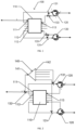
- light splitting processing of the downlink optical signal ⁇ down may be that a plurality of first downlink optical signals are obtained by light splitting processing of the star-shaped coupling module 110 itself and are output by the second side interfaces 113, as shown in FIG. 1 .
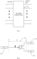
- a plurality of first downlink optical signals may also be obtained after light splitting processing is performed by other light splitting modules on the downlink optical signal input to the first public port 111, and are multiplexed to the first connection ports 1, and when the light splitting modules are splitters, it may refer to FIG. 2 .
- the optical distribution apparatus 100 of the embodiment of the present application can directly replace the splitter (i.e., Spliter in the illustration) in the existing networking, and may also be deployed in new networking.
- the optical distribution apparatus 100 of the embodiment of the present application may be applied to a single-fiber-to-the-home scenario as well as other PON application scenarios, for which the embodiment of the present application does not limit the use of the optical distribution apparatus 100.
- the first public port 111 is connected to the optical line terminal 200, thereby realizing a single-fiber-to-the-home scenario.
- the optical distribution apparatus 100 in the embodiment of the present application may be an integrated part or may be a combination of a separate star-shaped coupling module 110, annular members 120, and multiplexing module.
- a star-shaped coupler is used as the star-shaped coupling module 110
- circulators are used as the annular members 120
- a plurality of wavelength division multiplexers are combined to form the multiplexing module.
- the star-shaped coupler, the plurality of circulators, and the plurality of wavelength division multiplexers are combined to obtain the optical distribution apparatus 100 according to an optical path direction, and the number of the circulators is consistent with the number of ONUs in the actual application, and may also be consistent with the number of the first side branch interfaces 112, which is not limited by the embodiment of the present application.
- the number of the first public port 111 as 1 one of the first side interfaces on one side of the star-shaped coupler is used as the first public port 111, and one of the second side interfaces 113 on the other side of the star-shaped coupler is discarded.
- the uplink optical signal entering the second side interface 113 is output from any first side interface, and the first side interface that is not used as the first public port 111 can loop back this uplink signal to a first connection port of the circulator.
- the star-shaped coupler outputs the first downlink optical signals from the downlink optical signal ⁇ up input by the first public port 111 from any second side interface and multiplexes each of the output first downlink optical signals to the first connection port of one circulator through the wavelength division multiplexer.
- other structural combinations may also be adopted to realize functions of the star-shaped coupling module as in the present application, which is not limited by the embodiment of the present application.
- wavelengths of the uplink optical signal ⁇ up and the downlink optical signal ⁇ down used for service processing may be multiplexed when there is a need for the optical network apparatuses 400 to communicate with each other.
- a wavelength of the uplink optical signal used for service processing is ⁇ up
- a wavelength of the downlink optical signal used for service processing is ⁇ down .
- a wavelength of a burst signal may be set to ⁇ up . At this time, there is no need to use a third wavelength as the wavelength of the burst signal, thus saving spectrum resources.
- a fiber Bragg grating is usually arranged at a public end of the splitter to reflect the optical signal output by the public end of the splitter through the fiber Bragg grating.
- a frequency division multiplexing technique is utilized for a communication of the burst signal
- the loopback is realized by connecting the first connection port 121 to the first side interface, so for a plurality of ONUs, a time division multiplexing manner may be adopted for the communication during sending of the burst signal, and comparatively speaking, the amount of information for which the ONUs can communicate with each other in the embodiment of the present application may be set to be more.
- the burst signal is routed back and forth by OLTs, the OLTs need re-queuing and modulation so that each ONU can receive the burst signal, whereas in the present application, there is no need for re-routing, re-queuing, and re-modulation for the direct loopback, which enhances the reliability and energy efficiency of the network, i.e., a downlink bandwidth of the OLTs sending re-modulated communication signals between the ONUs to the ONUs is saved, and the utilization of the downlink bandwidth is improved.
- the direct communication between the ONUs can also significantly reduce communication latency.
- a real service wavelength may be output through the first public port 111 or the plurality of second connection ports 2, therefore, in the FTTH scenario, it is necessary only to replace the splitter of the FTTH with the splitter 100 of the present application, and then it is possible to use existing other devices to realize a single fiber optic resource to a user without additionally deploying optical fibers, which makes the transformation simpler.
- the wavelength division multiplexing modules each include a first wavelength division multiplexing member 131 and a second wavelength division multiplexing member 133, the first wavelength division multiplexing member is arranged between the first connection port 1 of the corresponding annular member 120 and the corresponding first side branch interface 112; and the second wavelength division multiplexing member 133 is arranged between the third connection port 3 of the corresponding annular member 120 and the corresponding second side interface 113.
- the first wavelength division multiplexing members 131 and the second wavelength division multiplexing members 133 outputs of the second side interfaces 113 are multiplexed to the first connection ports 1 in a downstream direction to realize the transmission of downstream services.
- the first wavelength division multiplexing members 131 are each configured to combine a first downlink optical signal with an uplink optical signal output by the corresponding first side branch interface 112 to the corresponding first connection port.
- the second wavelength division multiplexing member 133 is configured to output a first downlink optical signal output from the second side interface 113 from a demultiplexing port to a corresponding multiplexing port of the first wavelength division multiplexing member 131.
- a first wavelength division multiplexing member 131, a third wavelength division multiplexing member 132, a second wavelength division multiplexing member 133, and a first light splitting module 140 are arranged in the optical distribution apparatus 100.
- the optical distribution apparatus 100 When in a combined state, the optical distribution apparatus 100 may be obtained by combining the parts according to the actual application scenario.
- the optical distribution apparatus 100 When the optical distribution apparatus 100 is in an integrated mode, by arranging a plurality of switches, the optical distribution apparatus 100 may form an optical signal transmission direction shown in FIG. 1 in some cases or the optical distribution apparatus 100 may form an optical signal transmission direction shown in FIG. 2 in other cases, which is not limited by the embodiment of the present application.
- the wavelength division multiplexing modules each include a first wavelength division multiplexing member 131, and the first wavelength division multiplexing member 131 is arranged between the first connection port 1 of the corresponding annular member 120 and the corresponding first side branch interface 112.
- the first wavelength division multiplexing member 131 By arranging the first wavelength division multiplexing member 131 to multiplex the first downlink signal onto an optical path of the first side branch interface 112 and the first connection port 1, the first downlink signal can be output from the first connection port 1 to the second connection port 2.
- first connection port 1 and the first side branch interface 112 are connected by optical fibers.
- an external first light splitting module 140 may be arranged with first branch ends 142 connected to the first wavelength division multiplexing members 131 respectively, wherein the number of the first branch ends 142 of the first light splitting module 140 is greater than the number of the first wavelength division multiplexing members 131.
- the downlink optical signal ⁇ down is output from the first branch end 142 of the first light splitting module 140, it is multiplexed by the first wavelength division multiplexing member 131 to the optical path between the first connection port 1 and the first side branch interface 112, and the downlink service and the uplink optical signal are combined and then jointly output from the second connection port.
- the optical distribution apparatus 100 When the second public port 141 of the external first light splitting module 140 and the first public port 111 of the optical distribution apparatus 100 are multiplexed by the external third wavelength division multiplexing member 132, transmission of uplink services may be realized.
- the first light splitting module 140 By means of the first light splitting module 140, an optical signal of one wavelength can be divided into a plurality of different-power optical signals to be output respectively from the first branch ends 142.
- the optical distribution apparatus 100 is obtained by combining, in an actual application, remaining parts, the first light splitting module 140 and the third wavelength division multiplexing member 132, may be purchased according to the application scenario and combined to realize the structure shown in FIG. 2 , and in this regard, there is no limitation on a structural form of the optical distribution apparatus 100 of the embodiment of the present application.
- an external second wavelength division multiplexing member 133 may also be arranged to realize multiplexing of the first downlink signal as shown in FIG. 1 .
- the wavelength division multiplexing modules each further include a third wavelength division multiplexing member 132; and the third wavelength division multiplexing member 132 is connected to the first public port 111.
- the third wavelength division multiplexing member 132 is configured to output a downlink optical signal from a demultiplexing port to the second public port 141 of the first light splitting module 140.
- the first wavelength division multiplexing member 131 and the third wavelength division multiplexing member 132 are arranged in the optical distribution apparatus 100, it is possible to match only one first light splitting modules 140, and at this time, the deployment for the optical distribution apparatus 100 is simpler.
- the optical distribution apparatus 100 further includes a first light splitting module 140, a second public port 141 of the first light splitting module 140 is connected to the third wavelength division multiplexing member 132, and a plurality of first branch ends 142 of the first light splitting module 140 are respectively connected to the first wavelength division multiplexing members 131 of a plurality of the wavelength division multiplexing modules.
- the deployment manner of the optical distribution apparatus 100 can be further simplified by arranging the first light splitting module 140, the first wavelength division multiplexing member 131 and the third wavelength division multiplexing member 132 all in the optical distribution apparatus 100.
- the star-shaped coupling module 110 being an (N+1)x(N+1) star-shaped coupler as an example
- other N ports on the left side may be connected to a burst optical signal receiver of an operating wavelength ⁇ up of the ONU through a distribution fiber and a corresponding distribution fiber on a right side.
- a backbone fiber port No. 1 of the OLT on the left side of the star-shaped coupler corresponds to a distribution fiber port No.
- a downlink continuous optical signal at an operating wavelength ⁇ down on the OLT side and an uplink burst optical signal at an operating wavelength ⁇ up are demultiplexed by the third wavelength division multiplexer 132 and then enter an ordinary 1xN splitter to be split into N branch fibers for output.
- the uplink burst optical signal at an ONU operating wavelength ⁇ up enters the second connection port 2 of the annular member 120 through the distribution fiber, is output from the third connection port 3, is transmitted through the fiber on the right side of the star-shaped coupler to the left side, and is output from any port on the left side.
- the uplink burst optical signal is output from a port No. 1 on the left side of the star-shaped coupler to reach the OLT, and the uplink burst optical signals are output from the other N ports on the left side.
- An uplink burst optical signal at an operating wavelength ⁇ up output from a certain port on the left side is combined with a downlink optical signal at an operating wavelength ⁇ down output from a corresponding ordinary beam splitter through the third wavelength division multiplexing member 132, enters the first connection port 1 of the annular member 120, and is output from the second connection port 2.
- an optical distribution network unit 300 proposed according to an embodiment of the present disclosure includes at least one optical distribution apparatus 100 according to any one of the first aspect.
- a deployment manner of a PON system can be simplified by arranging the optical distribution network unit 300 including the optical distribution apparatus 100.
- a network system provided according to an embodiment of the present application includes:
- the use of at least one optical distribution apparatus 100 in the optical distribution network unit 300 reduces the loss of power once compared to the scenarios in which splitters are used, and therefore reduces the loss of power in the communication between the optical network apparatuses 400.
- a network system provided according to the present application includes:
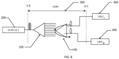
- the PON system consists of an OLT, an ONU at the user end, and a splitter 100 as an optical distribution network (ODN).
- OLT optical distribution network
- the OLT device remains unchanged, and other optical distribution network devices except for the splitter remain unchanged, by replacing an original 1xN splitter with the optical distribution apparatus 100 in the present application and replacing an original ONU with a new ONU, a point-to-multipoint communication between the optical line terminal 200 (OLT) and the optical network unit (ONU) is realized to be compatible with the direct internal communication between the optical network terminals (ONUs).
- OLT optical line terminal 200
- ONU optical network unit
- the star-shaped coupling module 110 being an (N+1)x(N+1) star-shaped coupler as an example
- a branch fiber port No. 1 (corresponding to the first public port 111) on a left side of the (N+1)x(N+1) star-shaped coupler that is connected through a backbone fiber
- other N ports on the left side may be connected to a burst optical signal receiver of an operating wavelength of the ONU through a distribution fiber and a corresponding distribution fiber on a right side.
- a backbone fiber port No. 1 of the OLT on the left side of the star-shaped coupler corresponds to a distribution fiber port No.
- a downlink continuous optical signal at an OLT operating wavelength ⁇ down is transmitted through the backbone fiber (corresponding to the first public port 111) on the left side of the star-shaped coupler to the right side and is output from all port branch fibers on the right side (corresponding to the second side interface 113).
- This downlink continuous optical signal at an operating wavelength ⁇ down and an uplink burst optical signal at an operating wavelength ⁇ up are split by the second wavelength division multiplexing member 133 and then separately led out from the port branch fiber.
- the uplink burst optical signal at an ONU operating wavelength ⁇ up enters the second connection port 2 of the annular member 120 through the distribution fiber, is output from the third connection port 3, is transmitted through the fiber on the right side of the star-shaped coupler to the left side, and is output from any port on the left side.
- the uplink burst optical signal is output from a port No. 1 on the left side of the star-shaped coupler to reach the OLT, and the uplink burst optical signals are output from the other N ports on the left side.
- An uplink burst optical signal at an operating wavelength ⁇ up output from a certain port on the left side is taken as an example, is combined with a downlink optical signal at an operating wavelength ⁇ down decomposed by the second wavelength division multiplexing member 131 and the second wavelength division multiplexing member 133 at the corresponding port on the right, enters the first connection port 1 of the circulator, and is output from the second connection port 2.
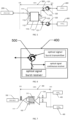
- the ONU includes a downlink optical signal continuous/burst receiver and an uplink optical signal burst transmitter and a three-port circulator 500.
- a downlink direction continuous/burst sent optical signal at a wavelength ⁇ down and an uplink burst optical signal at an operating wavelength ⁇ up enter a port 2 of the three-port circulator 500 from a distribution fiber, are output from a port 3 of the three-port circulator 500 and then enter the optical signal continuous receiver and the optical signal burst receiver respectively.
- An uplink burst optical signal at an optical signal wavelength of ⁇ up sent in the uplink direction in a burst enters the port 1 of the three-port circulator 500 and is output from the port 2 of the three-port circulator 500 to the second connection port 2 of the annular member 120 of the optical distribution apparatus 100.
- a network system provided according to an embodiment of the present application includes:
- the optical distribution apparatus 100 may be used in an ODN with multi-stage splitter networking to realize flexible network networking. Direct communications between all ONUs may be realized in the case where the optical distribution apparatus 100 is used in a first-stage splitter and a conventional splitter (corresponding to the second light splitting module 310) is used in a second-stage splitter to remain unchanged.
- the uplink burst optical signal only needs to pass through the first-stage optical distribution apparatus 100 once, but needs to pass through the second-stage splitter twice, and the embodiment of the present application can reduce the loss of power consumption once as compared to the structure in which the first and second stages both use splitters.
- a network system provided according to an embodiment of the present application includes:
- the optical distribution apparatus 100 is used in the second-stage splitter, and the uplink burst optical signal needs to pass through the first-stage optical distribution apparatus 100 only once to realize the direct communication between the ONUs where the second-stage splitter is located, and does not need to pass through the first-stage splitter even once. Therefore, compared with the conventional two-stage splitter, the network system of the embodiment of the present application is more capable of reducing the loss of communication between ONUs.
- FIG. 5 to FIG. 8 are networking of the network embodiments of the embodiments of the present application.
- the optical distribution apparatus 100 may be applied to networking other than FIG. 5 to FIG. 8 , such as arranging more than 3 levels of splitter networking, and other optical distribution apparatuses 100 or splitters are also added between the two optical distribution apparatuses 100 of FIG. 8 .
- those skilled in the art may obtain a network system other than the embodiments of the present application based on the optical distribution apparatus 100 of any one of the first aspect and in conjunction with the accompanying drawings 1 and 2.
- first wavelength division multiplexing member 131, the third wavelength division multiplexing member 132, and the second wavelength division multiplexing member 133 may be devices with the same functions as the wavelength division multiplexer, or they may be wavelength division multiplexers.
- Each of the third connection ports is connected to one second side interface, each of the second side interfaces communicates with the plurality of the first side interfaces, the first side interfaces are connected to the corresponding first connection ports, therefore, for each uplink optical signal input through the corresponding second connection port, after passing through the star-shaped coupling module once, it is looped back, by each of the first side branch interfaces, to an optical path where the first side branch interface and the corresponding first connection port are located to be combined with the first downlink signal and output from the second connection port, so as to realize a direct communication with a plurality of optical network apparatuses after passing through the star-shaped coupling module once.
- uplink optical signals of the plurality of second side interfaces are further sent to the first public port to be output, so that uplink direction transmission of single-fiber services can be realized when the uplink optical signals are service signals.
- the first downlink optical signals are multiplexed to the first connection ports through the corresponding wavelength division multiplexing modules and are output from the second connection ports, realizing the downlink direction transmission of service signals.
- the optical distribution apparatus of the embodiments of the present application is adopted to perform service transmission in a single-fiber scenario, and at the same time enables the optical signal for the direct communication between the optical network apparatuses to only need to pass through the star-shaped coupling module once without reflection, and the loss of optical power is lower, which is favorable for a practical application.
- the optical distribution apparatus, the optical distribution network unit, and the network system of the embodiments of the present application can reduce the loss of optical power during the direct communication between the optical network apparatuses.
Landscapes
- Physics & Mathematics (AREA)
- Engineering & Computer Science (AREA)
- General Physics & Mathematics (AREA)
- Optics & Photonics (AREA)
- Computer Networks & Wireless Communication (AREA)
- Signal Processing (AREA)
- Computing Systems (AREA)
- Electromagnetism (AREA)
- Optical Communication System (AREA)
Applications Claiming Priority (2)
| Application Number | Priority Date | Filing Date | Title |
|---|---|---|---|
| CN202210814181.6A CN117434664A (zh) | 2022-07-12 | 2022-07-12 | 分光装置、光配线网络单元和网络系统 |
| PCT/CN2023/106988 WO2024012488A1 (zh) | 2022-07-12 | 2023-07-12 | 分光装置、光配线网络单元和网络系统 |
Publications (2)
| Publication Number | Publication Date |
|---|---|
| EP4553552A1 true EP4553552A1 (de) | 2025-05-14 |
| EP4553552A4 EP4553552A4 (de) | 2025-11-19 |
Family
ID=89535579
Family Applications (1)
| Application Number | Title | Priority Date | Filing Date |
|---|---|---|---|
| EP23838978.7A Pending EP4553552A4 (de) | 2022-07-12 | 2023-07-12 | Optische verteilungsvorrichtung, optische verteilungsnetzwerkeinheit und netzwerksystem |
Country Status (4)
| Country | Link |
|---|---|
| US (1) | US20260016651A1 (de) |
| EP (1) | EP4553552A4 (de) |
| CN (1) | CN117434664A (de) |
| WO (1) | WO2024012488A1 (de) |
Family Cites Families (14)
| Publication number | Priority date | Publication date | Assignee | Title |
|---|---|---|---|---|
| JP4064787B2 (ja) * | 2002-11-07 | 2008-03-19 | 富士通株式会社 | 光加入者ネットワーク及び加入者宅光回線終端装置 |
| CN1874194A (zh) * | 2005-06-04 | 2006-12-06 | 杨淑雯 | 共光源光码分多址接入网 |
| CN101378388B (zh) * | 2007-08-28 | 2012-10-03 | 华为技术有限公司 | 一种无源光网络数据传输的方法、系统和设备 |
| CN101820352B (zh) * | 2009-11-03 | 2012-05-23 | 上海大学 | 波分复用无源光网络实现广播功能的系统和方法 |
| CN101729942B (zh) * | 2009-11-26 | 2012-11-07 | 上海大学 | 波分复用无源光网络实现环形局域网系统和方法 |
| CN103139670B (zh) * | 2011-11-25 | 2018-04-10 | 中兴通讯股份有限公司 | 共存无源光网络系统及上、下行光信号发送方法 |
| JP5821644B2 (ja) * | 2012-01-12 | 2015-11-24 | 沖電気工業株式会社 | 光信号中継装置、及び光通信ネットワークシステム |
| CN102754453B (zh) * | 2012-04-17 | 2015-07-29 | 华为技术有限公司 | 一种远端节点和无源光网络系统 |
| CN103686465B (zh) * | 2012-09-12 | 2016-12-21 | 上海贝尔股份有限公司 | 光网络节点、光网络单元和低延时的光网络单元间的通信 |
| CN103281610A (zh) * | 2013-06-19 | 2013-09-04 | 苏州彩云飞电子有限公司 | 多波长无源光网络系统 |
| CN103281603B (zh) * | 2013-06-19 | 2015-09-30 | 涂瑞强 | 多波长无源光网络系统 |
| WO2016049858A1 (zh) * | 2014-09-30 | 2016-04-07 | 华为技术有限公司 | 多路光收发模块和相关设备 |
| CN111355554B (zh) * | 2018-12-20 | 2023-04-28 | 中兴通讯股份有限公司 | 路由合波器、路由合波方法、波分路由方法及网络系统 |
| CN216252755U (zh) * | 2021-12-07 | 2022-04-08 | 罗森伯格技术有限公司 | 光模块 |
-
2022
- 2022-07-12 CN CN202210814181.6A patent/CN117434664A/zh active Pending
-
2023
- 2023-07-12 US US18/992,559 patent/US20260016651A1/en active Pending
- 2023-07-12 WO PCT/CN2023/106988 patent/WO2024012488A1/zh not_active Ceased
- 2023-07-12 EP EP23838978.7A patent/EP4553552A4/de active Pending
Also Published As
| Publication number | Publication date |
|---|---|
| WO2024012488A1 (zh) | 2024-01-18 |
| CN117434664A (zh) | 2024-01-23 |
| US20260016651A1 (en) | 2026-01-15 |
| EP4553552A4 (de) | 2025-11-19 |
Similar Documents
| Publication | Publication Date | Title |
|---|---|---|
| US8554079B2 (en) | Wavelength division and time division multiplex mixing passive optical network system, terminal and signal transmission method | |
| US6597482B1 (en) | Multiplexing/demultiplexing apparatus for wavelength division multiplexed system and wavelength division multiplexed passive optical subscriber networks using the same apparatus | |
| WO2005098994A1 (en) | Thread-type flexible battery | |
| EP0720314A1 (de) | Eindimensionale optische Matrize für optisches Netz | |
| US7450851B2 (en) | System and method for modularly scalable architecture for optical networks | |
| CN111355554A (zh) | 路由合波器、路由合波方法、波分路由方法及网络系统 | |
| CN1983906A (zh) | 一种波分复用无源光网络及实现方法 | |
| EP1443695A2 (de) | Vorrichtung für optische Übertragung und optisches Wellenlängenmultiplex-Netzwerk damit | |
| US20240056706A1 (en) | Electrical Switching Cluster System | |
| CN101098206B (zh) | 一种无源光网络系统及其光路处理方法 | |
| CN101471730B (zh) | 基于波分复用结构的光纤宽带接入系统及光网络单元 | |
| US8139939B2 (en) | Upgradeable passive optical network | |
| KR100594902B1 (ko) | 링 타입 광 전송 시스템 | |
| EP4553552A1 (de) | Optische verteilungsvorrichtung, optische verteilungsnetzwerkeinheit und netzwerksystem | |
| JP6221219B2 (ja) | 冗長システム、光通信装置及び親局装置 | |
| KR101013722B1 (ko) | 파장분할다중-수동광통신망의 통신채널 절체 시스템 및 방법 | |
| KR100602951B1 (ko) | 광 순환기를 채용한 wdm pon 시스템 | |
| KR100514385B1 (ko) | 버스형 wdm pon 시스템 | |
| KR100594901B1 (ko) | 센터 이중화 구조 파장 분할 다중화 방식 수동광 네트워크시스템 | |
| WO2025214583A1 (en) | Optical communication device | |
| KR100547721B1 (ko) | 광 증폭기 모듈 및 이를 이용한 광 전송 시스템 | |
| JP3379683B2 (ja) | 光伝送装置 | |
| JP3039435B2 (ja) | 光加入者伝送システム | |
| CN120378010A (zh) | 光收发器件、业务板和通信设备 | |
| JP2017147743A (ja) | 冗長システム、親局装置及び子局装置 |
Legal Events
| Date | Code | Title | Description |
|---|---|---|---|
| STAA | Information on the status of an ep patent application or granted ep patent |
Free format text: STATUS: THE INTERNATIONAL PUBLICATION HAS BEEN MADE |
|
| PUAI | Public reference made under article 153(3) epc to a published international application that has entered the european phase |
Free format text: ORIGINAL CODE: 0009012 |
|
| STAA | Information on the status of an ep patent application or granted ep patent |
Free format text: STATUS: REQUEST FOR EXAMINATION WAS MADE |
|
| 17P | Request for examination filed |
Effective date: 20250207 |
|
| AK | Designated contracting states |
Kind code of ref document: A1 Designated state(s): AL AT BE BG CH CY CZ DE DK EE ES FI FR GB GR HR HU IE IS IT LI LT LU LV MC ME MK MT NL NO PL PT RO RS SE SI SK SM TR |
|
| DAV | Request for validation of the european patent (deleted) | ||
| DAX | Request for extension of the european patent (deleted) | ||
| A4 | Supplementary search report drawn up and despatched |
Effective date: 20251017 |
|
| RIC1 | Information provided on ipc code assigned before grant |
Ipc: G02B 6/44 20060101AFI20251013BHEP Ipc: H04J 14/02 20060101ALI20251013BHEP Ipc: H04B 10/27 20130101ALI20251013BHEP |