EP4553271A1 - Bohrroboter mit einem aufblasbaren segment - Google Patents
Bohrroboter mit einem aufblasbaren segment Download PDFInfo
- Publication number
- EP4553271A1 EP4553271A1 EP23209221.3A EP23209221A EP4553271A1 EP 4553271 A1 EP4553271 A1 EP 4553271A1 EP 23209221 A EP23209221 A EP 23209221A EP 4553271 A1 EP4553271 A1 EP 4553271A1
- Authority
- EP
- European Patent Office
- Prior art keywords
- segment
- drilling robot
- drilling
- inflatable
- inflatable segment
- Prior art date
- Legal status (The legal status is an assumption and is not a legal conclusion. Google has not performed a legal analysis and makes no representation as to the accuracy of the status listed.)
- Withdrawn
Links
Images



Classifications
-
- E—FIXED CONSTRUCTIONS
- E21—EARTH OR ROCK DRILLING; MINING
- E21B—EARTH OR ROCK DRILLING; OBTAINING OIL, GAS, WATER, SOLUBLE OR MELTABLE MATERIALS OR A SLURRY OF MINERALS FROM WELLS
- E21B7/00—Special methods or apparatus for drilling
- E21B7/02—Drilling rigs characterised by means for land transport with their own drive, e.g. skid mounting or wheel mounting
- E21B7/027—Drills for drilling shallow holes, e.g. for taking soil samples or for drilling postholes
-
- E—FIXED CONSTRUCTIONS
- E21—EARTH OR ROCK DRILLING; MINING
- E21B—EARTH OR ROCK DRILLING; OBTAINING OIL, GAS, WATER, SOLUBLE OR MELTABLE MATERIALS OR A SLURRY OF MINERALS FROM WELLS
- E21B23/00—Apparatus for displacing, setting, locking, releasing or removing tools, packers or the like in boreholes or wells
- E21B23/001—Self-propelling systems or apparatus, e.g. for moving tools within the horizontal portion of a borehole
-
- E—FIXED CONSTRUCTIONS
- E21—EARTH OR ROCK DRILLING; MINING
- E21B—EARTH OR ROCK DRILLING; OBTAINING OIL, GAS, WATER, SOLUBLE OR MELTABLE MATERIALS OR A SLURRY OF MINERALS FROM WELLS
- E21B23/00—Apparatus for displacing, setting, locking, releasing or removing tools, packers or the like in boreholes or wells
- E21B23/01—Apparatus for displacing, setting, locking, releasing or removing tools, packers or the like in boreholes or wells for anchoring the tools or the like
-
- E—FIXED CONSTRUCTIONS
- E21—EARTH OR ROCK DRILLING; MINING
- E21B—EARTH OR ROCK DRILLING; OBTAINING OIL, GAS, WATER, SOLUBLE OR MELTABLE MATERIALS OR A SLURRY OF MINERALS FROM WELLS
- E21B33/00—Sealing or packing boreholes or wells
- E21B33/10—Sealing or packing boreholes or wells in the borehole
- E21B33/12—Packers; Plugs
- E21B33/1208—Packers; Plugs characterised by the construction of the sealing or packing means
Definitions
- the invention refers in a first aspect to a drilling robot for drilling a vertical bore hole and in a second aspect to an inflatable unit for the drilling robot.
- Boreholes for geothermal probes are traditionally drilled with a pneumatic hammer drill, wherein a compressor and a drill rig are arranged outside the borehole and the drill energy is transferred to the drill head inside the borehole via a drill pipe. Cuttings are flushed out of the borehole. Due to the water filled borehole, the pressure of the compressed air must increase along the depth of the borehole to actuate the pneumatic drill head. A very large compressor is needed to generate the necessary pressure and flow volume.
- an electrically driven and compact drilling robot might generate a torque on the drill head which needs to be supported.
- the problem to be solved by the present invention is therefore to provide a drilling robot that is adapted to overcome the disadvantages of the prior art.
- the drilling robot for drilling a vertical bore hole is in particular purely electrically driven.
- the drilling robot comprises a drill head and a first inflatable segment.
- the first inflatable segment is adapted to expand its volume in radial direction in an inflated state. In the inflated state, the first inflatable segment is adapted to absorb a torque that occurs when driving the drill head. This means that the inflatable segment is designed to handle the torque that occurs if the drill head is rotating to drill the bore hole.
- the drilling robot comprises further a drilling system.
- the drilling system is arranged between the drill head and the first inflatable segment.
- Such an arrangement might be advantageous for electrically driven drilling robots.
- the heavy weight of the drive close to the drill head might move the robot forward in vertical direction by gravitational forces.
- Such an arrangement might be further advantageous in regard that the drilling system generates a torque moment and a hammer stroke directly close by the drill head.
- the drilling system comprises a rotating system and a hammering system.
- the rotating system is adapted to rotate the drill head and the hammering system is adapted to hammer with the drill head.
- the hammering system is adapted to operate according to an electro-pneumatic principle in order to generate an electro-pneumatic stroke.
- the drilling robot comprises further a second inflatable segment.
- the second inflatable segment is also adapted to expand its volume in radial direction in an inflated state.
- the first and the second inflatable segment are arranged along a longitudinal axis of the drilling robot.
- the drilling robot is further adapted to alternate the state of the first inflatable segment and the second inflatable segment from inflated to deflated.
- at least the first or the second inflatable segment is in an inflated state.
- either the inflated first or the inflated second segment serves as the torque support on the bore wall.
- the torque support on the bore wall is provided by either the first inflated segment or the second segment.
- the arrangement with the first and the second segment allows the drilling robot to drill and move continuously, since always the first or the second segment acts as torque support and the forward movement of the drilling robot can be followed by alternating the inflation of the first and the second segment continuously.
- the drilling robot comprises further a third inflatable segment.
- the third inflatable segment is adapted to expand its volume in radial direction in an inflated state.
- the third inflatable segment is arranged along the longitudinal axis of the drilling robot.
- each of the first, the second and the third segment is further adapted to contract its axial length in axial direction of the longitudinal axis in an inflated state and to expand its axial length in a relaxed state.
- each of the first, second, and third segment in an inflated state, is designed to reduce (or diminish) its axial length along the direction of the longitudinal axis, while in a relaxed state, they are designed to increase their axial length.
- the first, second and third inflatable segments are arranged within the drilling robot or placed in the drilling unit in said order with the first inflatable segment directed in forward moving direction.
- the drilling robot in the intended use of the drilling robot, to move the drilling robot from a first position to a second position, the drilling robot is adapted to inflate the first, the second and/or the third inflatable segment and thereby engage the drilling robot with the borehole at the first position.
- engage means to direct the drilling robot to engage with the borehole to counteract a torque produced by the drilling head by drilling the borehole by means of the inflated segments.
- to engage the drilling robot with the borehole might also mean to activate the drilling robot that the first, second and/or third inflatable segments are inflated such that a torque of the drilling action of the robot is counteracted by at least one of the segments interacting respectively blocking the movement of the robot in the borehole.
- the drilling robot is adapted to subsequently relax the first and the second inflatable segment and thereby generate the advancing force to move the drilling robot to the second position and further subsequently inflate the first inflatable segment to frictionally engage the drilling robot in the borehole, respective with the inner surface of the borehole, at the second position.
- frictionally engaged means that the first segment is designed to establish a frictional connection of the drilling robot with the inner surface of the borehole.
- the segment is therefore intended for frictionally coupling the drilling robot respectively the surface of the first segment of the drilling robot, with the inner surface of the borehole.
- the drilling robot is adapted to subsequently relax the third segment and thereby bring the first, second and third segment into a position to start the next move, by continuing to inflate the first, the second, and/or the third segment at the new first position that corresponds to the previous second position.
- the first and the second inflatable segment are connected with an actuator.
- an actuator might be a single or double acting (hydraulic) cylinder.
- the actuator enables in particular a forward and/or a backward movement of the drilling robot, similar to a drilling robot comprising a third inflatable segment. Therefore, the actuator might replace the second inflatable segment in some embodiments of the drilling robot.
- the drilling robot comprises an energy reservoir to control the force acting on the drill head.
- the energy reservoir can be used to damp the drilling energy.
- the energy reservoir is arranged between the drilling system and the first inflatable element.
- the energy reservoir is an absorber, in particular a hydraulic cylinder or a spring element.
- the at least first, second and third segment are all of the same type of segments.
- the respective first, second and/or third segment is filled with a fluid or gas.
- the drilling robot comprises a medium-based, in particular water-based, very particular water-air-mix-based flushing system for flushing cuttings to the surface.
- the first, second and/or third inflatable segment if there are any, are arranged around the flushing system respectively around a part of the flushing system.
- the flushing system might be a part of the drilling robot that is encircled by the first, second and/or third segment.
- the flushing-system flushes the cuttings or mud to the surface by flushing them internally through a pipe or similar through the drilling robot to the surface.
- the functionality of the first, second and third segment is not affected.
- An advantageous flushing system is connected to a pump at the surface of the bore hole, to pump a flushing fluid into the flushing system and to pump cuttings out of the flushing system.
- the flushing system comprises at least one pathway, e.g. a pipe or tube, that allows to bring the flushing fluid, e.g. rinse water, or a power connection to the drill head to enable the flushing of cuttings right at the front of the drilling robot.
- the flushing fluid e.g. rinse water
- multiple pathways are integrated, e.g. one pathway for the flushing fluid and/or one for the power connection and/or one for bringing the cuttings or mud back to the surface.
- the pathways are adapted such that they do not impede the functionality of the at least one inflatable segment.
- the pathways that are used for the flushing fluid might at the same time be used as pathways to inflate and deflate (relax) at least the first inflatable segment, and/or the second and/or the third inflatable segment, if there are any.
- a second aspect of the invention refers to a inflatable unit for the drilling robot according to the first aspect of the invention and comprising at least a first inflatable segment.
- the inflatable unit comprises further a second and optionally even a third inflatable segment.
- a flushing system is arranged within the inflatable unit such that the at least first inflatable segment surrounds the flushing system.
- the flushing system is supposed to pass through the first inflatable segment without affecting the functionality of the first inflatable segment.
- the flushing system is adapted to transport cuttings from a bore hole to the surface of the bore hole via a drilling robot.
- the inflatable unit builds a part of the drilling robot, wherein the inflatable unit is adapted to absorb a torque that is generated by the drill head during the drilling of the bore hole.
- a further aspect of the invention not claimed is a method to generate a torque support for the in particular electrically driven drilling robot for drilling a vertical bore hole.
- the drilling robot comprises a drill head and a first inflatable segment.
- the method comprises the steps of:
- a further advantageous method moves the drilling robot from a first position to a second position.
- the drilling robot therefore comprises a second and a third inflatable segment.
- Each of the first, second and third segment is adapted to contract its axial length in axial direction of the longitudinal axis and to expand its volume in radial direction in an inflated state and to expand its axial length in a relaxed state.
- the first, second and third inflatable segments are arranged within the drilling robot in said order with the first inflatable segment directed in forward moving direction.
- the method comprises advantageously the steps of:
- Fig. 1 shows a schematic drawing of a drilling robot 100 for drilling a vertical bore hole.
- the drilling robot is sitting in the vertical bore hole.
- the drilling robot 100 is in particular purely electrically driven.
- the drilling robot 100 comprises an electronic unit 4 that controls the electrically driven robot 100.
- the drilling robot 100 comprises a drill head 2 and a first inflatable segment 11.
- the first inflatable segment 11 is adapted to expand its volume in radial direction in an inflated state. In the inflated state, the first inflatable segment 11 is adapted to absorb a torque that occurs when driving the drill head 2.
- the drilling robot 100 in the intended use of the robot 100, when drilling a vertical bore hole, produces cuttings that need to be transferred to the surface. Therefore, the robot comprises a flushing system (not visible in Fig.1 ) that transports the cuttings to the surface.
- the flushing system is arranged such that it does not impede the functionality of the first inflating segment.
- An advantageous flushing system 8 is connected to a pump at the surface of the bore hole, to pump a flushing fluid into the flushing system 8 and to pump cuttings out of the flushing system 8.
- the flushing system 8 comprises at least one pathway 81, e.g. a pipe or tube, that allows to bring the flushing fluid, e.g. rinse water, or a power connection to the drill head 2 to enable the flushing of cuttings right at the front of the drilling robot 100.
- the flushing fluid e.g. rinse water
- the pathways 81 that are used for the flushing fluid might at the same time be used as pathways to inflate and deflate (relax) at least the first inflatable segment 11, and/or the second 12 and/or the third 13 inflatable segment, if there are any.
- the drilling system 3 is arranged between the drill head 2 and the first inflatable segment 11.
- the drilling system 3 comprises a rotating system and a hammering system, wherein the rotating system is adapted to rotate the drill head 2 and wherein the hammering system is adapted to hammer with the drill head 2.
- the drilling robot 100 as shown in Fig. 1 comprises an energy reservoir 6 to control the axial force at the drill head.
- the drilling robot 100 would also work without the energy reservoir 6.
- the drilling robot 100 comprises a supply 5 for fluid, e.g. water, air pressure and/or power supply.
- a supply 5 for fluid e.g. water, air pressure and/or power supply.
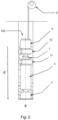
- Fig. 2 shows a schematic of a drilling robot 100 comprising further a second inflatable segment 12.
- the second inflatable segment 12 is also adapted to expand its volume in radial direction in an inflated state.
- the first 11 and the second 12 inflatable segment are arranged along a longitudinal axis a of the drilling robot 100.
- the first 11 and the second 12 inflatable segment are arranged in said order in a forward moving direction d of the drilling robot 100.
- the robot 100 is adapted to alternate the state of the first inflatable segment 11 and the second inflatable segment 12 from inflated to deflated. At least the first 11 or the second 12 inflatable segment is in an inflated state. The respective first 11 or second 12 inflatable segment serves as the torque support on the bore wall.
- the drilling robot 100 comprising the first 11 and the second 12 inflatable segment allows to continuously bore the bore hole, since while moving the robot 100 forward in the bore hole, the first 11 and second 12 inflatable segment are alternating inflated and deflated to follow the movement of the drilling robot 100 in the bore hole.
- the first 11 and the second 12 inflatable segment are connected with an actuator 7.
- an actuator 7 might be a single or double acting cylinder.
- the actuator 7 enables a forward movement of the drilling robot 100, similar to a drilling robot 100 comprising a third inflatable segment 13. Therefore, the actuator 7 might replace the second inflatable segment 12 in some embodiments of the drilling robot 100.
- both, the first 11 and the second 12 inflatable segment are in an inflated state.
- Fig. 3 shows a schematic figure of a drilling robot 100 comprising further a third inflatable segment 13 adapted to expand its volume in radial direction in an inflated state.
- the third inflatable segment 13 is arranged along the longitudinal axis a of the drilling robot 100.
- the first 11, second 12 and third 13 inflatable segments are arranged on a longitudinal axis a in said order in forward moving direction d of the robot.
- the drilling robot 100 In the intended use of the drilling robot 100, to move the drilling robot 100 from a first position to a second position, the drilling robot 100 is adapted to inflate the first 11, the second 12 and the third 13 inflatable segment and thereby engage the drilling robot 100 with the borehole at the first position.
- the drilling robot 100 is further adapted to subsequently relax the first 11 and the second 12 inflatable segment and thereby generate the advancing force to move the drilling robot 100 to the second position. Subsequently, the first inflatable segment 11 is inflated to frictionally engage the drilling robot 100 in the borehole at the second position.
- the drilling robot 100 comprises optionally an energy reservoir 6 to control the movement of the drill head 2 in axial direction.
- the energy reservoir is arranged between the drilling system 3 and the first inflatable segment 11.
- the energy reservoir is an absorber, in particular a hydraulic cylinder or a spring element.
- the first 11, the second 12 and the third 13 segment are all of the same type of segments (here the second segment 12 is deflated and the first 11 and third 13 segments are inflated, which is why they look differently).
- the first 11, the second 12, and the third 13 inflatable segment gets filled with gas or a fluid to become inflated.
- the drilling robot 100 comprises a medium-based flushing system 8 for flushing cuttings to the surface.
- the first inflatable segment 11 and the second inflatable segment 12 or the third inflatable segment 13, if there are any, are arranged around the flushing system 8.
- Fig. 4a and 4b show a schematic drawing of different embodiments of an inflatable unit 101 for the drilling robot 100 according to the first aspect of the invention.
- the inflatable unit 101 comprises at least a first 11, in particular as shown in Fig. 4 also a second 12 and a third 13 inflatable segment.
- the inflatable unit 101 comprises further a flushing system 8, wherein the first 11, the second 12, and the third 13 inflatable segment, if there are any, are arranged around the flushing system.
- the flushing system 8 comprises at least one pathway 81 for a flushing fluid and/or a power connection.
- Fig. 4b shows an embodiment with two pathways 81, one pathway for a flushing fluid and one pathway for a power connection.
- the pathway 81 for the flushing fluid might also be used to inflate and/or deflate the first 11, second 12, and/or third inflatable segment 13.
Landscapes
- Life Sciences & Earth Sciences (AREA)
- Engineering & Computer Science (AREA)
- Geology (AREA)
- Mining & Mineral Resources (AREA)
- Physics & Mathematics (AREA)
- Environmental & Geological Engineering (AREA)
- Fluid Mechanics (AREA)
- General Life Sciences & Earth Sciences (AREA)
- Geochemistry & Mineralogy (AREA)
- Earth Drilling (AREA)
Priority Applications (2)
| Application Number | Priority Date | Filing Date | Title |
|---|---|---|---|
| EP23209221.3A EP4553271A1 (de) | 2023-11-10 | 2023-11-10 | Bohrroboter mit einem aufblasbaren segment |
| PCT/EP2024/081505 WO2025099156A1 (en) | 2023-11-10 | 2024-11-07 | Drilling robot with an inflatable segment |
Applications Claiming Priority (1)
| Application Number | Priority Date | Filing Date | Title |
|---|---|---|---|
| EP23209221.3A EP4553271A1 (de) | 2023-11-10 | 2023-11-10 | Bohrroboter mit einem aufblasbaren segment |
Publications (1)
| Publication Number | Publication Date |
|---|---|
| EP4553271A1 true EP4553271A1 (de) | 2025-05-14 |
Family
ID=88779683
Family Applications (1)
| Application Number | Title | Priority Date | Filing Date |
|---|---|---|---|
| EP23209221.3A Withdrawn EP4553271A1 (de) | 2023-11-10 | 2023-11-10 | Bohrroboter mit einem aufblasbaren segment |
Country Status (2)
| Country | Link |
|---|---|
| EP (1) | EP4553271A1 (de) |
| WO (1) | WO2025099156A1 (de) |
Citations (2)
| Publication number | Priority date | Publication date | Assignee | Title |
|---|---|---|---|---|
| EP0110182A2 (de) * | 1982-11-26 | 1984-06-13 | Advanced Drilling Corporation | Tiefbohrvorrichtung |
| US20030034177A1 (en) * | 2001-08-19 | 2003-02-20 | Chitwood James E. | High power umbilicals for subterranean electric drilling machines and remotely operated vehicles |
Family Cites Families (1)
| Publication number | Priority date | Publication date | Assignee | Title |
|---|---|---|---|---|
| US10415314B2 (en) * | 2015-07-08 | 2019-09-17 | Halliburton Energy Services, Inc. | Downhole mechanical percussive hammer drill assembly |
-
2023
- 2023-11-10 EP EP23209221.3A patent/EP4553271A1/de not_active Withdrawn
-
2024
- 2024-11-07 WO PCT/EP2024/081505 patent/WO2025099156A1/en active Pending
Patent Citations (2)
| Publication number | Priority date | Publication date | Assignee | Title |
|---|---|---|---|---|
| EP0110182A2 (de) * | 1982-11-26 | 1984-06-13 | Advanced Drilling Corporation | Tiefbohrvorrichtung |
| US20030034177A1 (en) * | 2001-08-19 | 2003-02-20 | Chitwood James E. | High power umbilicals for subterranean electric drilling machines and remotely operated vehicles |
Also Published As
| Publication number | Publication date |
|---|---|
| WO2025099156A1 (en) | 2025-05-15 |
Similar Documents
| Publication | Publication Date | Title |
|---|---|---|
| CA2230185C (en) | Puller-thruster downhole tool | |
| US8408317B2 (en) | Tubular expansion tool and method | |
| US6286592B1 (en) | Puller-thruster downhole tool | |
| CA2736199C (en) | Pulse generator | |
| CA2686627C (en) | Electrically sequenced tractor | |
| NO335112B1 (no) | Rørekspansjonsverktøy og fremgangsmåte for ekspandering av rør | |
| US6742605B2 (en) | Percussion tool for generic downhole fluid motors | |
| EP2247814A1 (de) | Horizontales direktionales bohrsystem | |
| US10294745B2 (en) | Reaction valve drilling jar system | |
| WO2022199666A1 (zh) | 一种带有自适应支撑结构的旋转导向钻井工具 | |
| Liu et al. | A novel double bevel support structure for downhole robot | |
| CN1313698C (zh) | 液体驱动井下钻机 | |
| EP4553271A1 (de) | Bohrroboter mit einem aufblasbaren segment | |
| JP2005511933A (ja) | スラスト制御装置 | |
| CA2479236C (en) | Method and device for directional down-hole drilling | |
| CN110273682B (zh) | 一种用于矿产开采的冲击力强的凿岩机 | |
| CN1443266A (zh) | 倒划井眼工具 | |
| KR100940786B1 (ko) | 수직천공구 천공장치 | |
| CN120520512B (zh) | 一种采用节能气压驱动元件的水平定向钻装置及方法 | |
| US20260002414A1 (en) | Drilling robot | |
| CN104879073A (zh) | 一种连续推进液压钻井工具 | |
| CA2257308C (en) | A hydraulic device to be connected in a pipe string | |
| AU2021218225A1 (en) | Borehole casing system and method | |
| AU2922102A (en) | Electrically sequenced tractor | |
| NO20110031A1 (no) | Tubulært ekspansjonsverktøy og fremgangsmåte |
Legal Events
| Date | Code | Title | Description |
|---|---|---|---|
| PUAI | Public reference made under article 153(3) epc to a published international application that has entered the european phase |
Free format text: ORIGINAL CODE: 0009012 |
|
| STAA | Information on the status of an ep patent application or granted ep patent |
Free format text: STATUS: THE APPLICATION HAS BEEN PUBLISHED |
|
| AK | Designated contracting states |
Kind code of ref document: A1 Designated state(s): AL AT BE BG CH CY CZ DE DK EE ES FI FR GB GR HR HU IE IS IT LI LT LU LV MC ME MK MT NL NO PL PT RO RS SE SI SK SM TR |
|
| RAP3 | Party data changed (applicant data changed or rights of an application transferred) |
Owner name: BOROBOTICS AG |
|
| STAA | Information on the status of an ep patent application or granted ep patent |
Free format text: STATUS: THE APPLICATION IS DEEMED TO BE WITHDRAWN |
|
| 18D | Application deemed to be withdrawn |
Effective date: 20251115 |