EP4553243A1 - Geformte feste toilette aus recycelten materialien - Google Patents
Geformte feste toilette aus recycelten materialien Download PDFInfo
- Publication number
- EP4553243A1 EP4553243A1 EP24209964.6A EP24209964A EP4553243A1 EP 4553243 A1 EP4553243 A1 EP 4553243A1 EP 24209964 A EP24209964 A EP 24209964A EP 4553243 A1 EP4553243 A1 EP 4553243A1
- Authority
- EP
- European Patent Office
- Prior art keywords
- lavatory
- mold
- composition
- cull
- vitreous
- Prior art date
- Legal status (The legal status is an assumption and is not a legal conclusion. Google has not performed a legal analysis and makes no representation as to the accuracy of the status listed.)
- Pending
Links
Images


Classifications
-
- B—PERFORMING OPERATIONS; TRANSPORTING
- B29—WORKING OF PLASTICS; WORKING OF SUBSTANCES IN A PLASTIC STATE IN GENERAL
- B29C—SHAPING OR JOINING OF PLASTICS; SHAPING OF MATERIAL IN A PLASTIC STATE, NOT OTHERWISE PROVIDED FOR; AFTER-TREATMENT OF THE SHAPED PRODUCTS, e.g. REPAIRING
- B29C39/00—Shaping by casting, i.e. introducing the moulding material into a mould or between confining surfaces without significant moulding pressure; Apparatus therefor
- B29C39/003—Shaping by casting, i.e. introducing the moulding material into a mould or between confining surfaces without significant moulding pressure; Apparatus therefor characterised by the choice of material
- B29C39/006—Monomers or prepolymers
-
- B—PERFORMING OPERATIONS; TRANSPORTING
- B29—WORKING OF PLASTICS; WORKING OF SUBSTANCES IN A PLASTIC STATE IN GENERAL
- B29B—PREPARATION OR PRETREATMENT OF THE MATERIAL TO BE SHAPED; MAKING GRANULES OR PREFORMS; RECOVERY OF PLASTICS OR OTHER CONSTITUENTS OF WASTE MATERIAL CONTAINING PLASTICS
- B29B17/00—Recovery of plastics or other constituents of waste material containing plastics
- B29B17/0005—Direct recuperation and re-use of scrap material during moulding operation, i.e. feed-back of used material
-
- A—HUMAN NECESSITIES
- A47—FURNITURE; DOMESTIC ARTICLES OR APPLIANCES; COFFEE MILLS; SPICE MILLS; SUCTION CLEANERS IN GENERAL
- A47K—SANITARY EQUIPMENT; ACCESSORIES THEREFOR, e.g. TOILET ACCESSORIES
- A47K1/00—Wash-stands; Appurtenances therefor
- A47K1/04—Basins; Jugs; Holding devices therefor
-
- B—PERFORMING OPERATIONS; TRANSPORTING
- B29—WORKING OF PLASTICS; WORKING OF SUBSTANCES IN A PLASTIC STATE IN GENERAL
- B29C—SHAPING OR JOINING OF PLASTICS; SHAPING OF MATERIAL IN A PLASTIC STATE, NOT OTHERWISE PROVIDED FOR; AFTER-TREATMENT OF THE SHAPED PRODUCTS, e.g. REPAIRING
- B29C39/00—Shaping by casting, i.e. introducing the moulding material into a mould or between confining surfaces without significant moulding pressure; Apparatus therefor
- B29C39/003—Shaping by casting, i.e. introducing the moulding material into a mould or between confining surfaces without significant moulding pressure; Apparatus therefor characterised by the choice of material
-
- B—PERFORMING OPERATIONS; TRANSPORTING
- B29—WORKING OF PLASTICS; WORKING OF SUBSTANCES IN A PLASTIC STATE IN GENERAL
- B29C—SHAPING OR JOINING OF PLASTICS; SHAPING OF MATERIAL IN A PLASTIC STATE, NOT OTHERWISE PROVIDED FOR; AFTER-TREATMENT OF THE SHAPED PRODUCTS, e.g. REPAIRING
- B29C39/00—Shaping by casting, i.e. introducing the moulding material into a mould or between confining surfaces without significant moulding pressure; Apparatus therefor
- B29C39/02—Shaping by casting, i.e. introducing the moulding material into a mould or between confining surfaces without significant moulding pressure; Apparatus therefor for making articles of definite length, i.e. discrete articles
-
- B—PERFORMING OPERATIONS; TRANSPORTING
- B29—WORKING OF PLASTICS; WORKING OF SUBSTANCES IN A PLASTIC STATE IN GENERAL
- B29C—SHAPING OR JOINING OF PLASTICS; SHAPING OF MATERIAL IN A PLASTIC STATE, NOT OTHERWISE PROVIDED FOR; AFTER-TREATMENT OF THE SHAPED PRODUCTS, e.g. REPAIRING
- B29C39/00—Shaping by casting, i.e. introducing the moulding material into a mould or between confining surfaces without significant moulding pressure; Apparatus therefor
- B29C39/22—Component parts, details or accessories; Auxiliary operations
- B29C39/26—Moulds or cores
-
- B—PERFORMING OPERATIONS; TRANSPORTING
- B29—WORKING OF PLASTICS; WORKING OF SUBSTANCES IN A PLASTIC STATE IN GENERAL
- B29K—INDEXING SCHEME ASSOCIATED WITH SUBCLASSES B29B, B29C OR B29D, RELATING TO MOULDING MATERIALS OR TO MATERIALS FOR MOULDS, REINFORCEMENTS, FILLERS OR PREFORMED PARTS, e.g. INSERTS
- B29K2105/00—Condition, form or state of moulded material or of the material to be shaped
- B29K2105/06—Condition, form or state of moulded material or of the material to be shaped containing reinforcements, fillers or inserts
- B29K2105/16—Fillers
-
- B—PERFORMING OPERATIONS; TRANSPORTING
- B29—WORKING OF PLASTICS; WORKING OF SUBSTANCES IN A PLASTIC STATE IN GENERAL
- B29L—INDEXING SCHEME ASSOCIATED WITH SUBCLASS B29C, RELATING TO PARTICULAR ARTICLES
- B29L2031/00—Other particular articles
- B29L2031/769—Sanitary equipment
- B29L2031/7694—Closets, toilets
-
- E—FIXED CONSTRUCTIONS
- E03—WATER SUPPLY; SEWERAGE
- E03C—DOMESTIC PLUMBING INSTALLATIONS FOR FRESH WATER OR WASTE WATER; SINKS
- E03C1/00—Domestic plumbing installations for fresh water or waste water; Sinks
- E03C1/12—Plumbing installations for waste water; Basins or fountains connected thereto; Sinks
- E03C1/14—Wash-basins connected to the waste-pipe
-
- E—FIXED CONSTRUCTIONS
- E03—WATER SUPPLY; SEWERAGE
- E03C—DOMESTIC PLUMBING INSTALLATIONS FOR FRESH WATER OR WASTE WATER; SINKS
- E03C1/00—Domestic plumbing installations for fresh water or waste water; Sinks
- E03C1/12—Plumbing installations for waste water; Basins or fountains connected thereto; Sinks
- E03C1/18—Sinks, whether or not connected to the waste-pipe
Definitions
- the present application relates to manufacturing a molded solid lavatory from recycled materials for use in a bathroom or kitchen setting.
- Lavatories commonly known as sinks or washbasins, are essential fixtures in residential, commercial, and industrial spaces, serving as fundamental elements of hygiene and sanitation.
- Traditional lavatories are primarily constructed from materials such as ceramic, porcelain, or stainless steel, which offer durability and aesthetic appeal.
- the manufacturing processes for these conventional lavatories often involve high energy consumption, intricate designs, and limited flexibility in shape and size.
- This disclosure aims to provide a sustainable solution that reduces waste, energy consumption, and production costs.
- the combination of recycled materials, efficient molding techniques, and curing processes allows for more environmentally responsible practices in manufacturing.
- this disclosure adaptability allows for the creation of lavatories in various shapes, sizes, and designs, catering to diverse consumer preferences and requirements.
- a method of manufacturing a lavatory includes: mixing vitreous cull, particulate matter, and resin to form a composition; pouring the composition into a mold; and curing the composition in the mold to form the lavatory.
- another method of manufacturing a lavatory includes: mixing vitreous cull, fiberglass resin composite cull, particulate matter, and resin; pouring the composition into a mold; and curing the composition in the mold to form the lavatory.
- a lavatory in another example embodiment for manufacturing a lavatory includes: mixing vitreous cull, fiberglass resin composite cull, particulate matter, and resin; providing one or more coatings to the inside of a mole; pouring the composition into a mold; and curing the composition in the mold to form the lavatory.
- a method of manufacturing a lavatory includes assembling an ejection frame configured to: secure to the mold below the lavatory in an upside-down position along a plurality of feet of the lavatory; insert a bolt of the ejection frame through a center drain of the lavatory; contact a bowl of the lavatory; and lift the lavatory from the mold.
- Natural and engineered stone surfaces have desirable aesthetics including natural veins and distinct geometric patterns.
- natural and engineered stone surfaces are expensive. Production of natural stone surfaces requires access to stone quarries and stone surfaces are limited to flat surfaces that must be sealed. Additionally, the production of natural and engineered stone surfaces requires the use of expensive specialized equipment. Accordingly, there exists a need for inexpensive solid surface products having desirable aesthetics.
- Described herein are methods of manufacturing molded lavatories and assembling an ejection frame to remove the lavatory from the mold. More specifically, the present disclosure describes methods of manufacturing molded lavatories from recycled materials including vitreous cull, fiberglass resin composite cull, particulate matter, and resin.
- the vitreous material, or vitreous china may be crushed, or otherwise broken or fragmented parts of a plumbing fixture such as a toilet, lavatory, bathtub, or basin.
- the plumbing fixture was fired at a high temperature until it is hardened.
- the plumbing fixture may be recycled and become part of the vitreous cull based on a manufacturing defect or after the lifetime (product cycle) of the plumbing fixture.
- composition created from these recycled materials may provide a lavatory with desirable aesthetics.
- the method may provide less expensive alternatives to natural and engineered stone surfaces.
- Other materials usable in any of the following examples include pottery cull, cast iron slag, waste glaze, enamel powder, foundry dust, and foundry sand.
- portions of the vitreous cull may have not been fired. Examples include trimmed pieces or scraps from another manufacturing process.
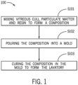
- Figure 1 illustrates a flowchart for the method 100 of manufacturing a lavatory 500. Additional different or fewer acts may be provided.
- vitreous cull, particulate matter, and resin may be mixed to form a composition.
- the resinous material may be in a liquid phase and comprise a mixture of two or more liquids.
- one of the liquids may include the epoxy groups used and another liquid may be a hardener (e.g., an epoxy curing agent).
- the ferrous particles may be mixed into the resinous material while the resinous material is in a liquid phase.
- the ferrous particles may be mixed into the resinous material such that they are distributed throughout the resinous material.
- a filler material and/or a colorant may further be mixed into the resinous material.
- the resin material may be acrylic, polystyrene, urethane, polyester, epoxy, hybrid composite, or eco-resin.
- the mixing process ensures the even distribution of these components, creating a uniform and blend.
- catalysts are added to control the rate of polymerization which facilitate the reaction without being consumed in the process.
- Cross-linking occurs when the polymer chains are chemically bonded at specific points, creating a network structure.
- Cross-linked resins tend to be stronger, more rigid, and have higher heat resistance compared to non-cross-linked ones.
- Eco-resins may be used as a substitute for the resin in the composition.
- Eco-resins also known as environmentally friendly resins or bio-based resins, are a category of resins designed to have reduced environmental impact compared to traditional petroleum-based resins. These resins are developed with a focus on sustainability, utilizing renewable resources and eco-friendly manufacturing processes.
- eco-resins are sourced from renewable materials.
- Common renewable sources include plant-based materials such as corn, soy, sugarcane, and other biomass.
- eco-resins are biodegradable or compostable, meaning they can break down naturally over time into harmless compounds. This property is a consideration in applications where the end product is not intended to be disposable but where reducing environmental impact is a priority.
- eco-resins are designed to be recyclable, allowing the material to be reclaimed and reused in new products. Recycling helps reduce the demand for raw materials and minimizes waste. Also, eco-resins are generally formulated to have low toxicity, making them safer for both the environment and human health. Reduced emissions of harmful substances contribute to improved air and water quality.
- a mold 400 may be pre-treated with one or more coatings or layers that are adhered at least to the inner surface of the mold 400.
- a first layer or coating may be applied (e.g., sprayed) directly against the inner surface of the mold 400.
- the first layer or coating may include at least a polyurethane component.
- the first layer or coating may encourage color fastness on the lavatory (e.g., reduce yellowing).
- the first layer or coating may perform an ultraviolet protection for the lavatory.
- a second layer or coating may be applied (e.g., sprayed) to the first layer or coating and indirectly to the inner surface of the mold 400.
- the second layer or coating may be a clear gel-coat.
- the second layer or coating may protect the mold surface from the abrasive properties of the cull or other materials of the composition that are placed into the mold 400.
- the mold 400 may be a high temperature resistant aluminum gelcoat with a fiberglass backing.
- the composition 300 is poured or placed into the mold 400.
- the composition 300 may be placed into the mold by a mechanically driven device.
- a mechanically driven device One example is illustrated in Figure 3 and described below.
- Another example may include a pump connected to a hose to pneumatically drive the composition 300 into the mold 400.
- the mold may comprise a mold upper half 401 and a mold lower half 402. At S102, the mold may be closed, such that the mold upper half 401 and the mold lower half 402 form a sealed, enclosed space having the desired shape of the lavatory 500.
- the homogeneous mixture is then poured into a pre-designed mold 400.
- the mold 400 is a hollow cavity with the exact negative shape of the desired lavatory 500.
- the poured composition 300 fills the mold 400, taking its shape and contours.
- composition 300 is cured in the mold 400 to form the lavatory 500.
- Curing begins after the composition is poured into the mold 400.
- the curing process can involve various techniques, including chemical reactions or exposure to specific environmental conditions such as heat, pressure, or ultraviolet (UV) light.
- the choice of curing technique depends on the composition 300 and the material used.
- curing involves chemical reactions between the components of the mixture.
- the resin undergoes polymerization-a chemical reaction where small molecules (monomers) combine to form large, interconnected molecules (polymers). This reaction results in the hardening of the composition 300.
- the molecules within the resin cross-link or form bonds with adjacent molecules. This process creates a three-dimensional network of interconnected molecules, transforming the material from a liquid or semi-liquid state into a solid structure.
- the material continues to solidify.
- the bonds between molecules strengthen, and the material becomes more rigid and stable. This solidification process ensures that the final product will have the necessary strength and durability.
- vitrifying or vitrification, and may be utilized.
- Vitrification is the process of transforming a material into a glass or glass-like substance. This process typically involves heating a material to a high temperature until it melts and then rapidly cooling it to form an amorphous, non-crystalline solid. Vitrification results in a smooth, glossy, and often transparent or translucent surface.
- Curing is the process of hardening a material, often involving chemical reactions, while vitrification is the specific process of transforming a material into a glassy state through controlled heating and cooling.
- the two processes serve different purposes but can be interconnected in certain manufacturing applications.
- the lavatory 500 is allowed to cool and fully harden within the mold 400. Once the material has achieved its optimal strength and stability, the lavatory 500 may be removed from the mold 400.
- Figure 2 illustrates a flowchart for the method 200 of manufacturing a lavatory 500.
- the mold 400 may be the same as that discussed above with reference to method 100 and Figure 1 .
- the resin and particulate matter may be the same as those discussed above with respect to method 100 and Figure 1 . Additional different or fewer acts may be provided.
- vitreous cull, fiberglass resin composite cull, particulate matter, and resin may be mixed to form a composition 300.
- the resinous material may be in a liquid phase and comprise a mixture of two or more liquids.
- one of the liquids may include the epoxy groups used and another liquid may be a hardener (e.g., an epoxy curing agent).
- a filler material and/or a colorant may further be mixed into the resinous material.
- the composition 300 is poured into a mold 400.
- the mold 400 may comprise a mold upper half 401 and a mold lower half 402.
- the mold 400 may be closed, such that the mold upper half 401 and the mold lower half 402 form a sealed, enclosed space having the desired shape of the lavatory 500.
- the composition 300 is cured in the mold 400 to form the lavatory 500.
- composition and curing process may be the same as those discussed above with reference to method 100 and Figure 1 .
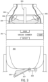
- FIG 3 illustrates an example apparatus for mixing a composition 300.
- the apparatus may include a vacuum chamber 301, a hopper 302, a vibration generator 303, and a mixing chamber 304.
- the mixing chamber 304 includes a shaft 305 that supports one or more blades 306.
- the blades 306 may be curved and angled to cut through the composition 300.
- the mixing chamber 304 is connected to the vacuum chamber 301 and the vacuum chamber 301 connects to the hopper 302.
- the hopper 302 may include a trapdoor 307 or another type of ramp or pathway to release the composition 300 from the hopper 302 and from the apparatus. Other arrangements are possible.
- the vacuum chamber 301 is upstream of the mixing chamber 304. Additional, different or fewer components may be included.
- the mixing chamber 304 is configured to mix vitreous cull, fiberglass resin composite cull, particulate matter, and resin to form a composition 300. Prior to mixing, fragmenting the vitreous cull into pieces less than one inch in length, width, and height may be beneficial to allow the ingredients to be small enough to be mixed effectively. The size of the pieces of the ingredients after fragmenting may be the recommended size above or smaller or larger, depending on the specific use, molding technique, or desired final product.
- mechanical methods such as stirring, whisking, shaking, or blending may be used to mix the ingredients to form the composition 300.
- the choice of tool depends on the viscosity and nature of the ingredients.
- High-speed agitation methods like using blenders or mixers, are effective for creating homogeneous mixtures, especially for materials with different densities.
- Maintaining a consistent mixing technique such as stirring in the same direction at a constant speed, helps distribute the ingredients evenly. Reversing the direction of stirring can sometimes aid in breaking up clumps and ensuring uniformity.
- homogenization may be used which is a mechanical process that reduces particle sizes in a composition 300 to achieve a uniform texture.
- the mixing chamber 304 provides the composition 300 to the vacuum chamber 301.
- the vacuum chamber 301 may be sealed. A door may be closed between the mixing chamber 304 and the vacuum chamber 301 after the composition 300 or portion thereof flows into the vacuum chamber 301.
- the vacuum chamber 301 may include a pump to pull air from the sealed vacuum chamber 301. The vacuum may aid in releasing trapped bubbles of air from the composition 300.
- the hopper 302 may be directly connected to the vacuum chamber 301.
- the vacuum chamber 301 may include an outlet that is open and closed by a valve so that the composition 300 can fall from the vacuum chamber 301 into the hopper 302.
- the hopper 302 provides a flow path to help release trapped bubbles of air from the composition 300.
- the vibration generator 303 may be constructed as a motor with a weight or unbalanced load.
- the vibration generator 303 may be constructed as a speaker having a low frequency. The vibrations may aid in releasing trapped bubbles of air from the composition 300.
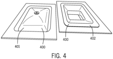
- Figure 4 illustrates sealing the mold 400 prior to the pouring of the composition 300 into the mold 400 and the curing of the composition 300 in the mold 400 to form the lavatory 500.
- Figure 4 includes a mold upper half 401 and a mold lower half 402. The sealed, enclosed interior of the mold upper half 401 and the mold lower half 402 may form the desired shape of the molded lavatory.
- Coating the mold 400 with a release agent may prevent the composition 300 from sticking to the mold 400. Steps may be taken to ensure the mold 400 is clean and dry. For example, the mold 400 may be dried and/or cleaned by contact or by air flow. Mold 400 preparation encourages simple demolding (e.g., removal of the lavatory from the mold 400) and a smooth surface finish.
- Figure 5 illustrates an alternative manual embodiment of pouring the composition 300 into the mold 400 which is in the desired shape of the lavatory.
- the manual embodiment is an alternative to the mixing and pouring apparatus illustrated in Figure 3 .
- One or more pouring techniques may be used to ensure the composition 300 evenly fills the mold 400, creating a high-quality, defect-free final lavatory 500.
- the composition 300 may be poured into the mold 400 in a controlled manner while avoiding splashing or pouring too quickly to reduce the number of air bubbles introduced into the mixture. Air bubbles can weaken the final product and affect the appearance of the lavatory 500.
- the viscosity of the composition 300 viscosity may also determine the appropriate pouring technique. For low-viscosity compositions, a steady, continuous pour may be suitable. For thicker mixtures, consider pouring in layers, allowing each layer to settle and degas before adding the next. This pouring technique may also help minimize the entrapment of air bubbles.
- other methods of removing trapped air bubbles may be used such as after pouring the composition, gently tapping the mold, or use a vibrating tool to help the material settle and eliminate air pockets. Vibration encourages the composition 300 to flow into the entire mold 400, ensuring uniformity.
- the composition 300 and mold 400 may be ensured to be level by using a leveling tool to maintain an even surface, especially if the mold 400 must be filled to a specific height.
- the composition 300 may be placed into the mold 400 using a hose or pipe.
- the hose or pope may be pneumatically or hydraulically driven to propel the composition 300.
- Figure 6 illustrates the composition 300 curing in the mold 400 with mold upper half 401 on top of the mold lower half 402.
- One or more clamps 403 may be used to couple and press together the mold upper half 401 and the mold lower half 402.
- the lavatory may also be glazed by spraying or otherwise applying a glassy coating to a surface of the lavatory.
- Figure 7 illustrates a method for assembling an ejection frame 700 configured to: secure to the mold upper half 401 below the lavatory 500 in an upside-down position along a plurality of feet 701 of the lavatory 500; insert a bolt 703 of the ejection frame 700 through a center drain 704 of the lavatory 500; contact a bowl 702 of the lavatory 500; and lift the lavatory 500 from the mold upper half 401.
- the bolt 703 may be inserted through a center drain 704 of the lavatory 500 that has an endpiece that may make contact with the bowl 702 of the lavatory 500.
- the bolt 703 may be raised by cranking a turning mechanism at the end of the bolt opposite the endpiece.
- the plurality of feet 701 of the lavatory 500 may be secured to the mold upper half 401 and/or another surface if necessary.
- the plurality of feet 701 of the lavatory 500 creates opposing force to the bolt 703 that allow the lavatory 500 to be removed from the mold upper half 401.
- the lavatory 500 is leveraged from the mold upper half 401 by rotating a bolt 703 through a center drain 704 to slowly and precisely apply upward force to the lavatory 500 and eventually remove the lavatory 500 from the mold upper half 401.
- inventions of the disclosure may be referred to herein, individually and/or collectively, by the term "invention" merely for convenience and without intending to voluntarily limit the scope of this application to any particular invention or inventive concept.
- inventions may be referred to herein, individually and/or collectively, by the term "invention" merely for convenience and without intending to voluntarily limit the scope of this application to any particular invention or inventive concept.
- specific embodiments have been illustrated and described herein, it should be appreciated that any subsequent arrangement designed to achieve the same or similar purpose may be substituted for the specific embodiments shown.
- This disclosure is intended to cover any and all subsequent adaptations or variations of various embodiments. Combinations of the above embodiments, and other embodiments not specifically described herein, will be apparent to those of skill in the art upon reviewing the description.
Landscapes
- Engineering & Computer Science (AREA)
- Environmental & Geological Engineering (AREA)
- Mechanical Engineering (AREA)
- Health & Medical Sciences (AREA)
- Public Health (AREA)
- Casting Or Compression Moulding Of Plastics Or The Like (AREA)
Applications Claiming Priority (2)
| Application Number | Priority Date | Filing Date | Title |
|---|---|---|---|
| US202363597478P | 2023-11-09 | 2023-11-09 | |
| US18/916,425 US20250153396A1 (en) | 2023-11-09 | 2024-10-15 | Molded solid lavatory from recycled materials |
Publications (1)
| Publication Number | Publication Date |
|---|---|
| EP4553243A1 true EP4553243A1 (de) | 2025-05-14 |
Family
ID=93335099
Family Applications (1)
| Application Number | Title | Priority Date | Filing Date |
|---|---|---|---|
| EP24209964.6A Pending EP4553243A1 (de) | 2023-11-09 | 2024-10-30 | Geformte feste toilette aus recycelten materialien |
Country Status (3)
| Country | Link |
|---|---|
| US (1) | US20250153396A1 (de) |
| EP (1) | EP4553243A1 (de) |
| CN (1) | CN119974347A (de) |
Citations (5)
| Publication number | Priority date | Publication date | Assignee | Title |
|---|---|---|---|---|
| US5218013A (en) * | 1988-09-23 | 1993-06-08 | Schock & Co. Gmbh | Component, in particular, built-in sink, and method for its manufacture |
| US5451362A (en) * | 1992-11-27 | 1995-09-19 | Ciba-Geigy Corporation | Moulding process |
| US20110204540A1 (en) * | 2010-02-22 | 2011-08-25 | Monroe Industries, Inc. | Cast polymer and recycled glass composite article |
| US20140121301A1 (en) * | 2012-10-25 | 2014-05-01 | Kohler Co. | Engineered composite material and products produced therefrom |
| WO2023135544A1 (en) * | 2022-01-17 | 2023-07-20 | Delta Srl | Composition for kitchen or bathroom furnishings, such as sinks, washbasins, worktops, tubs and sheets |
-
2024
- 2024-10-15 US US18/916,425 patent/US20250153396A1/en active Pending
- 2024-10-30 EP EP24209964.6A patent/EP4553243A1/de active Pending
- 2024-11-08 CN CN202411588399.XA patent/CN119974347A/zh active Pending
Patent Citations (5)
| Publication number | Priority date | Publication date | Assignee | Title |
|---|---|---|---|---|
| US5218013A (en) * | 1988-09-23 | 1993-06-08 | Schock & Co. Gmbh | Component, in particular, built-in sink, and method for its manufacture |
| US5451362A (en) * | 1992-11-27 | 1995-09-19 | Ciba-Geigy Corporation | Moulding process |
| US20110204540A1 (en) * | 2010-02-22 | 2011-08-25 | Monroe Industries, Inc. | Cast polymer and recycled glass composite article |
| US20140121301A1 (en) * | 2012-10-25 | 2014-05-01 | Kohler Co. | Engineered composite material and products produced therefrom |
| WO2023135544A1 (en) * | 2022-01-17 | 2023-07-20 | Delta Srl | Composition for kitchen or bathroom furnishings, such as sinks, washbasins, worktops, tubs and sheets |
Also Published As
| Publication number | Publication date |
|---|---|
| US20250153396A1 (en) | 2025-05-15 |
| CN119974347A (zh) | 2025-05-13 |
Similar Documents
| Publication | Publication Date | Title |
|---|---|---|
| CA2769492C (en) | Method for manufacturing non-flat agglomerated stone products | |
| US9221190B2 (en) | Production plant for forming engineered composite stone slabs | |
| CN104520082B (zh) | 模制方法和装置 | |
| EP3322569A1 (de) | Produktionsanlage zur formung manipulierter verbundsteinplatten | |
| CN103118846A (zh) | 用于板件生产的混合物 | |
| EP4553243A1 (de) | Geformte feste toilette aus recycelten materialien | |
| KR20140131556A (ko) | 분말 페인트 폐기물의 재활용 방법 및 상기 방법으로부터 얻은 제품 | |
| GB1604405A (en) | Articles made from resin compositions containing aggregate materials eg glass | |
| CN107383339A (zh) | 卫浴部件基材的制备方法、卫浴部件基材、卫浴部件 | |
| JP3700647B2 (ja) | 人造大理石の製造方法 | |
| KR100537761B1 (ko) | 거푸집용 코팅합판의 제조방법 | |
| CN111925178B (zh) | 一种加气混凝土砌块的制备工艺 | |
| KR101293340B1 (ko) | 초대형 칩을 이용한 인조대리석 및 이의 제조방법 | |
| JP2002255672A (ja) | 人造大理石 | |
| KR101453787B1 (ko) | 위생기기의 논코팅 제조방법 | |
| AU2021106735A4 (en) | Paving material compositions and production processes therefor | |
| KR102949590B1 (ko) | 인조대리석 및 이의 제조방법 | |
| CN101065225B (zh) | 利用铸塑系统以有或无abs增强来制造合成花岗岩卫生器具丙烯酸板材的方法 | |
| US12590030B2 (en) | Vaults, lids and trenches using recycled polystyrene | |
| JP2007099572A (ja) | レジンコンクリート成形品 | |
| CN1872570B (zh) | 玻璃砂岩雕制品的制作工艺 | |
| JP2004189519A (ja) | 二次製品用早強セメント材料及びセメント成形二次製品 | |
| CN117447230A (zh) | 一种软瓷材料及其制备方法 | |
| US20050244600A1 (en) | Method and apparatus for forming a finished article of manufacture and a finished article of manufacture made by a new and novel process | |
| AU2022218641A1 (en) | Paving material compositions and production processes therefor |
Legal Events
| Date | Code | Title | Description |
|---|---|---|---|
| PUAI | Public reference made under article 153(3) epc to a published international application that has entered the european phase |
Free format text: ORIGINAL CODE: 0009012 |
|
| STAA | Information on the status of an ep patent application or granted ep patent |
Free format text: STATUS: THE APPLICATION HAS BEEN PUBLISHED |
|
| AK | Designated contracting states |
Kind code of ref document: A1 Designated state(s): AL AT BE BG CH CY CZ DE DK EE ES FI FR GB GR HR HU IE IS IT LI LT LU LV MC ME MK MT NL NO PL PT RO RS SE SI SK SM TR |
|
| STAA | Information on the status of an ep patent application or granted ep patent |
Free format text: STATUS: REQUEST FOR EXAMINATION WAS MADE |
|
| 17P | Request for examination filed |
Effective date: 20251105 |
|
| STAA | Information on the status of an ep patent application or granted ep patent |
Free format text: STATUS: EXAMINATION IS IN PROGRESS |
|
| 17Q | First examination report despatched |
Effective date: 20251217 |