EP4553036A1 - Verfahren und anlage zum behandeln von dosen - Google Patents
Verfahren und anlage zum behandeln von dosen Download PDFInfo
- Publication number
- EP4553036A1 EP4553036A1 EP24211387.6A EP24211387A EP4553036A1 EP 4553036 A1 EP4553036 A1 EP 4553036A1 EP 24211387 A EP24211387 A EP 24211387A EP 4553036 A1 EP4553036 A1 EP 4553036A1
- Authority
- EP
- European Patent Office
- Prior art keywords
- sterilization
- nozzle
- filling
- sterilization medium
- cans
- Prior art date
- Legal status (The legal status is an assumption and is not a legal conclusion. Google has not performed a legal analysis and makes no representation as to the accuracy of the status listed.)
- Pending
Links
Images
Classifications
-
- B—PERFORMING OPERATIONS; TRANSPORTING
- B67—OPENING, CLOSING OR CLEANING BOTTLES, JARS OR SIMILAR CONTAINERS; LIQUID HANDLING
- B67C—CLEANING, FILLING WITH LIQUIDS OR SEMILIQUIDS, OR EMPTYING, OF BOTTLES, JARS, CANS, CASKS, BARRELS, OR SIMILAR CONTAINERS, NOT OTHERWISE PROVIDED FOR; FUNNELS
- B67C7/00—Concurrent cleaning, filling, and closing of bottles; Processes or devices for at least two of these operations
- B67C7/0073—Sterilising, aseptic filling and closing
-
- B—PERFORMING OPERATIONS; TRANSPORTING
- B65—CONVEYING; PACKING; STORING; HANDLING THIN OR FILAMENTARY MATERIAL
- B65B—MACHINES, APPARATUS OR DEVICES FOR, OR METHODS OF, PACKAGING ARTICLES OR MATERIALS; UNPACKING
- B65B55/00—Preserving, protecting or purifying packages or package contents in association with packaging
- B65B55/02—Sterilising, e.g. of complete packages
- B65B55/04—Sterilising wrappers or receptacles prior to, or during, packaging
- B65B55/10—Sterilising wrappers or receptacles prior to, or during, packaging by liquids or gases
-
- A—HUMAN NECESSITIES
- A61—MEDICAL OR VETERINARY SCIENCE; HYGIENE
- A61L—METHODS OR APPARATUS FOR STERILISING MATERIALS OR OBJECTS IN GENERAL; DISINFECTION, STERILISATION OR DEODORISATION OF AIR; CHEMICAL ASPECTS OF BANDAGES, DRESSINGS, ABSORBENT PADS OR SURGICAL ARTICLES; MATERIALS FOR BANDAGES, DRESSINGS, ABSORBENT PADS OR SURGICAL ARTICLES
- A61L2/00—Disinfection or sterilisation of materials or objects, in general; Accessories therefor
- A61L2/16—Disinfection or sterilisation of materials or objects, in general; Accessories therefor using chemical substances
- A61L2/20—Gaseous substances, e.g. vapours
- A61L2/208—Hydrogen peroxide
-
- A—HUMAN NECESSITIES
- A61—MEDICAL OR VETERINARY SCIENCE; HYGIENE
- A61L—METHODS OR APPARATUS FOR STERILISING MATERIALS OR OBJECTS IN GENERAL; DISINFECTION, STERILISATION OR DEODORISATION OF AIR; CHEMICAL ASPECTS OF BANDAGES, DRESSINGS, ABSORBENT PADS OR SURGICAL ARTICLES; MATERIALS FOR BANDAGES, DRESSINGS, ABSORBENT PADS OR SURGICAL ARTICLES
- A61L2103/00—Materials or objects being the target of disinfection or sterilisation
- A61L2103/23—Containers other than laboratory or medical, e.g. bottles or mail
-
- B—PERFORMING OPERATIONS; TRANSPORTING
- B67—OPENING, CLOSING OR CLEANING BOTTLES, JARS OR SIMILAR CONTAINERS; LIQUID HANDLING
- B67C—CLEANING, FILLING WITH LIQUIDS OR SEMILIQUIDS, OR EMPTYING, OF BOTTLES, JARS, CANS, CASKS, BARRELS, OR SIMILAR CONTAINERS, NOT OTHERWISE PROVIDED FOR; FUNNELS
- B67C3/00—Bottling liquids or semiliquids; Filling jars or cans with liquids or semiliquids using bottling or like apparatus; Filling casks or barrels with liquids or semiliquids
- B67C3/02—Bottling liquids or semiliquids; Filling jars or cans with liquids or semiliquids using bottling or like apparatus
- B67C3/22—Details
- B67C2003/228—Aseptic features
-
- B—PERFORMING OPERATIONS; TRANSPORTING
- B67—OPENING, CLOSING OR CLEANING BOTTLES, JARS OR SIMILAR CONTAINERS; LIQUID HANDLING
- B67C—CLEANING, FILLING WITH LIQUIDS OR SEMILIQUIDS, OR EMPTYING, OF BOTTLES, JARS, CANS, CASKS, BARRELS, OR SIMILAR CONTAINERS, NOT OTHERWISE PROVIDED FOR; FUNNELS
- B67C3/00—Bottling liquids or semiliquids; Filling jars or cans with liquids or semiliquids using bottling or like apparatus; Filling casks or barrels with liquids or semiliquids
- B67C3/02—Bottling liquids or semiliquids; Filling jars or cans with liquids or semiliquids using bottling or like apparatus
- B67C3/22—Details
- B67C3/26—Filling-heads; Means for engaging filling-heads with bottle necks
- B67C2003/2657—Filling-heads; Means for engaging filling-heads with bottle necks specially adapted for filling cans
Definitions
- the invention relates to a method for treating cans by internally sterilizing the cans.
- the invention further relates to a can treatment system with a sterilization device.
- filled and sealed beverage cans can be thermally treated in a pasteurizer. This ensures the microbiological safety of the contents, thus protecting the consumer and extending the shelf life of the contents.
- a disadvantage of pasteurization is that, although it is very safe, it is very energy-intensive. Furthermore, the contents of the can can be subjected to significant thermal stress during pasteurization. This can negatively impact the flavor of the contents. Valuable ingredients such as vitamins can also be damaged during the thermal pasteurization process.
- the invention is based on the object of providing an improved technique for treating cans, which is preferably faster, more effective and/or more efficient than the conventional technique, e.g. with a pasteurizing device.
- One aspect of the present disclosure relates to a method for treating cans (e.g., beverage cans or food cans) in a can treatment plant.
- the method comprises supplying (e.g., blowing or injecting) a sterilization medium, preferably comprising Hydrogen peroxide, into a can by means of a sterilization device.
- the method comprises internally sterilizing the can by means of the supplied sterilization medium while the can is transported to a filling station (e.g., a can filling device, e.g., a can filler carousel) (and preferably reaches the filling station).
- a filling station e.g., a can filling device, e.g., a can filler carousel
- the method comprises rinsing the can in the filling station with a purge gas, preferably carbon dioxide, whereby the sterilization medium is (e.g., completely) flushed out of the can.
- the method comprises filling the rinsed can in the filling station with a (e.g., liquid or pasty) filling material.
- the method does not simply allow for sterilization of the cans prior to filling.
- the method advantageously allows for the steps of removing (blowing out) the sterilization medium from the cans and rinsing the cans prior to filling to be integrated or carried out jointly.
- the rinsing performed before filling a can e.g., with CO2
- to reduce the oxygen content in the can is (also) used to rinse the sterilization medium from the can, thereby eliminating the need for a separate step for removing the sterilization medium in the sterilization device.
- both air with the oxygen it contains and the sterilization medium can be rinsed from the can.
- the process can be advantageously particularly fast, as a separate, several-second blow-out time before the can filling device or filling station can be eliminated. Depending on the machine's performance, several meters of transport distance can be saved.
- the transport time to the can filling device and the process time in the filling station up to rinsing represent additional exposure times for the sterilization medium. This also advantageously shortens the exposure time and thus the transport time in the sterilization device, allowing the sterilization device to be designed comparatively small.
- the process can be particularly effective because a comparatively long exposure time is available for internal sterilization.
- the sterilization medium acts against microorganisms within the can for a long time (from addition to complete rinsing).
- the extended exposure time makes the process particularly safe and effective. Due to the long exposure time, a comparatively low concentration of the sterilization medium and/or a reduced amount of the sterilization medium can be used for internal sterilization of the cans.
- special measures to increase the effectiveness of the Sterilization medium can be dispensed with, such as temperature activation and/or condensation of the sterilization medium on the inside of the container.
- the process can be particularly energy-efficient, for example, because it saves media.
- the rinsing can be carried out indirectly or immediately before filling or immediately before pre-tensioning the can in the filling station before filling.
- the sterilization medium is gaseous or substantially gaseous during supply and/or internal sterilization.
- the supplied sterilization medium can be supplied in such a way that it does not condense in the container and/or that it retains its gaseous state in the container.
- the comparatively long exposure time of the sterilization medium can eliminate the need for complex processing technology for activating and/or condensing the sterilization medium.
- the supplied sterilization medium remains essentially in the container until rinsing. This advantageously allows for particularly effective internal sterilization of the container.
- the can is transported linearly and/or upright through the sterilization device during the supply of the sterilization medium.
- the can can be transported upright to the filling station during internal sterilization (e.g., using a can conveyor). This advantageously ensures that as little sterilization medium as possible escapes from the can.
- the purge gas is supplied to the filling station via a preferably central purge gas supply channel during purging.
- the sterilization medium is purged into a preferably annular purge gas discharge channel of the filling station during purging.
- the method further comprises sucking the sterilization medium out of the can in the filling station, preferably when rinsing the can in the filling station.
- the sterilization medium is supplied via at least one nozzle of the sterilization device. This advantageously allows for precise delivery of the sterilization medium into the container.
- the at least one nozzle comprises at least one stationary nozzle, and the can moves past the at least one stationary nozzle during the supply of the sterilization medium. This advantageously enables a structurally simple design of the sterilization device.
- the at least one nozzle comprises at least one movable nozzle.
- the at least one movable nozzle can move with the can during the supply of the sterilization medium. This can advantageously support a particularly reliable and sufficient filling of the cans with the sterilization medium.
- the at least one movable nozzle can advantageously ensure that, depending on the geometry of the can, even hard-to-reach areas of the can can be reached by the sterilization medium.
- the amount of sterilization medium discharged from the at least one nozzle is constant. This advantageously minimizes the effort required to control the sterilization device.
- the amount of sterilization medium discharged from the at least one nozzle can be adjusted depending on the transport speed of the can along the at least one nozzle (e.g., automatically by a control device). This advantageously allows sufficient filling of the can with the sterilization medium while simultaneously saving sterilization medium.
- control device can refer to electronics (e.g., implemented as a driver circuit or with microprocessor(s) and data memory) and/or a mechanical, pneumatic, and/or hydraulic control system, which, depending on its design, can perform control tasks and/or regulation tasks and/or processing tasks. Even if the term “control” is used herein, it can also appropriately include or mean “regulation” or “control with feedback” and/or “processing.”
- This also advantageously allows sufficient filling of the container with the sterilization medium while simultaneously saving sterilization medium.
- the method further comprises sterilizing at least one section of the filling station using the sterilization medium flushed out of the can (e.g., directly during rinsing from the container), wherein the at least one section preferably has a filling material outlet of the filling station and/or a sealing surface of the filling station.
- the sterilization medium can thus be used in two ways: primarily for internal sterilization of the container and secondarily for sterilizing parts of the filling station during rinsing from the container.
- the filled can is not pasteurized in the can treatment plant.
- a further aspect of the present disclosure relates to a can processing plant, which is preferably designed to carry out a method as disclosed herein.
- the can processing plant comprises a sterilization device configured to supply a preferably gaseous sterilization medium, preferably comprising hydrogen peroxide, into cans.
- the can treatment system comprises a can filling device (e.g., a can filling carousel) arranged downstream of the sterilization device and having at least one filling station configured to rinse the cans, to flush the sterilization medium out of the cans, and to fill the cans with a filling material.
- the can treatment system can achieve the same advantages as those already explained with reference to the method.
- the can processing system further comprises a can conveyor that directly connects the sterilization device to the can filling device.
- the can processing system may be free of a pasteurization device for pasteurizing the cans after filling.
- the can processing system may not comprise any device configured to remove the sterilization medium from the cans from the beginning of the sterilization device to the can filling device.
- the sterilization device may comprise at least one nozzle for supplying the sterilization medium to the cans.
- the at least one nozzle may comprise at least one stationary nozzle and/or at least one movable nozzle.
- the sterilization device may include a can conveyor for transporting the cans while the sterilization medium is being supplied to the cans.
- the can conveyor is preferably configured to transport the cans upright and/or linearly through the sterilization device.
- the sterilization device may comprise a housing (e.g. tunnel-shaped or block-shaped) in which the at least one nozzle and/or the can conveyor are arranged.
- a housing e.g. tunnel-shaped or block-shaped
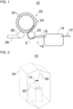
- the Figure 1 shows a can processing system 10, i.e., a system 10 for processing cans 12.
- the cans 12 can be, for example, beverage cans or food cans.
- the can processing system 10 can be designed as a can filling system.
- the cans 12 are handled and transported in the can processing system 10 using so-called base handling.
- the can processing system 10 includes a sterilization device 14 and a can filling device 22 with at least one filling station 24.
- the sterilization device 14 can also be referred to as a disinfection device.
- the can processing system 10 can further include a can conveyor 16.
- the sterilization device 14 introduces or supplies a sterilization medium into the cans 12.
- the sterilization device 14 can inject the sterilization medium into the cans 12.
- the sterilization medium can also be referred to as a disinfection medium.
- the sterilization medium supplied by the sterilization device 14 is preferably gaseous or at least substantially gaseous.
- the supplied sterilization medium can fill the cans 12.
- the sterilization medium can remain in the cans 12, for example, due to gravity and due to an upright orientation of the cans 12.
- the supplied sterilization medium can preferably be supplied by the sterilization device 14 in such a way that it does not condense in the can 12 and that it maintains its (essentially) gaseous state in the can 12.
- the cans 12 can have a temperature corresponding to the ambient temperature before, during, and/or after supply. It is possible for the sterilization medium to be supplied to the can 12 at a temperature that prevents condensation of the sterilization medium in the can 12 and/or supports maintenance of the (essentially) gaseous state of the sterilization medium in the can 12. It is also possible for the cans 12 and/or the sterilization medium to be preheated, for example, before the sterilization medium is supplied and/or reheated after the sterilization medium is supplied.
- the sterilization medium can preferably be or comprise hydrogen peroxide.
- the sterilization medium is preferably vaporized before being supplied.
- the sterilization medium can, for example, be supplied to the cans 12 as a mixture with air.
- the supplied sterilization medium sterilizes the cans 12 internally while the cans 12 are transported to the filling stations 24.
- the sterilization medium remains gaseous or at least substantially gaseous during internal sterilization.
- the cans 12 can be transported directly or via the can conveyor 16 to the filling stations 24.
- the cans 12 can preferably be transported upright from the sterilization device 14 to the respective filling station 24.
- the can treatment system 10 does not have a device designed to remove the sterilization medium from the cans 12 with respect to a can flow through the can treatment system 10 from the beginning of the sterilization device 14 up to the can filling device 22.
- the supplied sterilization medium can internally sterilize the cans 12 during transport along an exposure path E.
- the exposure path E can extend, for example, from a position in the sterilization device 14 at which the sterilization medium is supplied to the respective can 12.
- the exposure path E can extend to the respective filling station 24 at a position at which the respective filling station 24 begins to flush the respective can 12 with a flushing gas.
- the sterilization medium can essentially remain and act in the can 12.
- the can conveyor 16 may directly connect the sterilization device 14 to the can filling device 22.
- the can conveyor 16 may be located directly downstream of the sterilization device 14 with respect to a can flow through the can processing system 10.
- the can conveyor 16 may be located directly upstream of the can filling device 22 with respect to a can flow through the can processing system 10.
- the can conveyor 16 can transport the cans 12 preferably in an upright position, for example in base handling.
- the can conveyor 16 can, for example, have a linear conveyor 18 and/or an infeed starwheel 20.
- the linear conveyor 18 can receive the cans 12 from the sterilization device 14 and transfer them to the infeed starwheel 20.
- the infeed starwheel 20 can transfer the cans 12 one after the other to the filling stations 24.
- the infeed starwheel 20 can, for example, receive the cans directly from the sterilization device 14 or from the linear conveyor 18.
- the can filling device 22 is arranged downstream (in terms of cans) of the sterilization device 14 with respect to a can flow through the can processing system 10.
- the can filling device 22 can be arranged directly downstream of the sterilization device 14.
- the can filling device 22 can be arranged, for example, directly downstream of the can conveyor 16, which in turn can be arranged directly downstream of the sterilization device 14.
- the can filling device 22 preferably has a plurality of filling stations 24.
- one can 12 can be processed in each of the multiple filling stations 24.
- a plurality of the cans 12 can be processed simultaneously or at least in a temporally overlapping manner in the multiple filling stations 24.
- the can filling device 22 can be designed as a can filling carousel or a rotary can filler.
- the filling stations 24 can be arranged distributed around a circumference of the can filling device 22.
- the can filling device 22 it is also possible for the can filling device 22 to be, for example, a linear can filler with several filling stations arranged in series one behind the other and/or next to each other (not shown). Figure 1 shown).
- the filling station 24 is designed to rinse a respective can 12 to flush the sterilization medium out of the can 12. Rinsing can be performed, for example, immediately before filling or immediately before pre-pressurization prior to filling.
- the filling station 24 flushes the respective can 12 with a flushing gas, whereby the sterilization medium is flushed out of the can 12 after the internal sterilization of the can 12.
- oxygen can also be flushed out of the can 12.
- the flushing gas is preferably a process gas of the can filling device 22.
- the flushing gas is carbon dioxide.
- the rinsing of the can 12, i.e. the rinsing out of the sterilization medium and possibly oxygen during rinsing, in the filling station 24 is additionally supported by suctioning off the sterilization medium by means of the filling station 24.
- the sterilization medium flushed out of the can 12 can sterilize at least one area of the filling station 24 as it flows out of the can 12.
- the sterilization medium can pass through a filling material outlet of the filling station 24 and/or sealing surfaces of the filling station 24 and thereby sterilize them.
- the rinsed sterilization medium can be collected and reused, e.g., by the sterilization device 14.
- the filling station 24 is also designed to fill the cans 12 with a filling material.
- the filling station 24 fills the respective can 12 after rinsing, for example, immediately after rinsing or after pre-pressurizing the can 12.
- the filling material is preferably a liquid or pasty filling material, for example, a beverage or a food product.
- the filling station 24 can, for example, be an aseptic filling station for aseptically filling the cans 12 with the filling material.
- the filling station 24 can also evacuate the respective can 12, e.g., before or after rinsing, and/or pre-tension it, e.g., after rinsing.
- the cans 12 can be transported, for example, to a closing device (not in Figure 1
- the closing device can close the filled cans 12 with a can lid.
- the closing device can, for example, have at least one closing head for closing the cans.
- the closing device can preferably be designed as a closing carousel or a rotary closer.
- the can treatment plant 10 may be free of a pasteurization device for pasteurizing the cans 12 after filling.
- the can processing system 10 can have additional can processing devices, such as a depalletizing device and/or a rinsing device (e.g., with rinsing nozzles), which can be arranged, for example, upstream (in terms of cans) of the sterilization device 14.
- the can processing system 10 can have, for example, the already mentioned closing device, an adhesive pack manufacturing device (e.g., with adhesive application nozzles), a packaging device (e.g., with packing heads or film wrappers), and/or a palletizing device (e.g., with palletizing heads, sliding plates, or the like), which can be arranged, for example, downstream (in terms of cans) of the can filling device 22.
- the can processing plant 10 may have additional can conveyors for transporting the cans 12 through the can processing plant 10.
- the additional can conveyors may comprise at least one transport star and/or at least one linear conveyor.
- an outlet star 26 may receive the cans 12 filled by the can filling device 22 and transfer them to a downstream can conveyor 28, for example, a linear conveyor, for further transport.
- the Figures 2 and 3 show an exemplary embodiment of the sterilization device 14.
- the at least one nozzle 30 can supply the sterilization medium to the cans 12 or introduce/fill it into the cans 12. Preferably, the at least one nozzle 30 does not dip into the respective can 12 when supplying the sterilization medium to the respective can 12.
- the at least one nozzle 30 may comprise at least one stationary nozzle.
- the respective can 12 may move past the stationary nozzle during the supply of the gaseous sterilization medium from the stationary nozzle.
- the at least one nozzle 30 may have at least one movable nozzle.
- the movable nozzle may move with the respective can 12 during the supply of the sterilization medium from the movable nozzle.
- the movable nozzle may, for example, be pivotable to follow the moving respective can 12.
- the movable nozzle may, for example, be displaceable to follow the moving respective can 12.
- the displaceable nozzle may, for example, move back and forth or move along a closed path.
- the sterilization device 14 can have at least one drive, for example, an electric motor, for driving a movement of the movable nozzle. It is possible for the drive for driving the movement of the movable nozzle to be coupled to a drive of the can conveyor 32. It is also possible for the drive for driving the movement of the movable nozzle to also drive the can conveyor 32.
- an electric motor for driving a movement of the movable nozzle.
- the sterilization device 14 may further comprise at least one guide for guiding the movement of the movable nozzle.
- the at least one guide may comprise, for example, a pivoting guide, a linear guide, and/or a track guide.
- the at least one nozzle 30 can, for example, have a nozzle that blows the sterilization medium vertically from above and centrally into the can 12. Additionally or alternatively, the at least one nozzle 30 can, for example, have a nozzle that blows the sterilization medium vertically from above and off-center into the can 12. Additionally or alternatively, the at least one nozzle 30 can, for example, have a nozzle that blows the sterilization medium from above at an angle to a vertical axis of the can 12.
- a sterilization medium jet emanating from the nozzle can preferably be angled to a vertical axis of the can 12 at an angle of between 10° and 20°, particularly preferably approximately 15°.
- the at least one nozzle 30 can, for example, discharge a constant amount of sterilization medium.
- the sterilization medium discharge amount can be adjusted depending on the transport speed of the can 12 or the can conveyor 32 along the at least one nozzle 30, e.g., automatically by a control device.
- the sterilization medium can be delivered in pulsed fashion from the at least one nozzle 30, e.g., with one or more pulses per can 12.
- a pulse frequency can be adapted to a frequency of cans 12 moving past the at least one nozzle 30.
- a pulse duration can be adapted to a transport speed (e.g., of the can conveyor 32) at which the can 12 is moved past the at least one nozzle 30.
- the can conveyor 32 can transport the cans 12 through the sterilization device 14.
- the can conveyor 32 is preferably a linear conveyor.
- the linear conveyor can transport the cans 12 linearly through the sterilization device 14.
- the cans 12 can be transported upright by the can conveyor 32.
- the can conveyor 32 can transport the cans 12, for example, using base handling.
- the can conveyor 32 can be a belt conveyor, a mat chain conveyor, or a plate conveyor.
- the can conveyor 32 can transport the cans 12 through the sterilization device 14, for example, in a single lane, multiple lanes, or in a random mass flow.
- the at least one nozzle 30 and/or the can conveyor 32 can be arranged in the housing 34 of the sterilization device 14.
- the housing 34 can, for example, have a tunnel shape or a block shape.
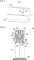
- the Figure 4 shows a portion of an exemplary embodiment of the filling station 24.
- the filling station 24 may, for example, have a filling valve 36, a purge gas supply channel 50, a purge gas discharge channel 54, a seal 60 and/or a can support 62.
- the filling valve 36 can fill the can 12 positioned below the filling valve 36 with the filling material.
- the filling valve 36 can have a movable valve member 38 for opening and closing the filling valve 24.
- the valve member 38 can be movable along a central axis M of the filling valve 36 or the filling station 24.
- the central axis M can be a central longitudinal axis (central vertical axis) of the filling valve 36 or the filling station 24.
- the valve member 38 can be movable relative to a preferably funnel-shaped valve seat 40 of the filling valve 36.
- the valve seat 40 can preferably be a valve cone seat.
- the valve member 38 can release a fluid connection between a filling material chamber 42 and a filling material outlet 44 of the filling valve 36.
- a filling material supply line (not shown in Figure 4 ) may be connected to the filling material chamber 42 for supplying filling material to the filling material chamber 42.
- the filling material can flow from the filling material chamber 42 to an annular gap between the valve member 38 and the valve seat 40 and from there to the filling material outlet 44.
- the filling material outlet 44 can, for example, be designed as an annular gap.
- the annular gap can, for example, be delimited on the inner circumference by the valve member 38.
- the filling material outlet 44 can be arranged coaxially to the central axis M.
- the valve member 38 can widen in a funnel shape in the region of the filling material outlet 44 toward a free end of the valve member 38.
- the valve member 38 may extend through the filling material chamber 42.
- the valve member 38 may be sealed from the filling material chamber 42 by a bellows 46.
- valve member 38 In a closed position, the valve member 38 can block the fluid connection between the filling material chamber 42 and the filling material outlet 44 of the filling valve 36, as shown for example in Figure 4 is shown.
- the filling material from the filling material chamber 42 cannot pass through the valve member 38 which is in sealing contact with the valve seat 40.
- the valve member 38 can be prestressed by means of an elastic element (e.g. a spring, preferably a helical compression spring) in a direction along the central axis M, e.g. for opening or closing the filling valve 36.
- an elastic element e.g. a spring, preferably a helical compression spring
- the valve member 38 can be moved by means of an actuator in a direction along the central axis M against the elastic prestress be movable, e.g., to open or close the filling valve 36.
- the actuator may be a pneumatic actuator or an electromagnetic actuator.
- the valve member 38 may have a preferably annular sealing element 48 for sealing with the valve seat 40.
- the sealing element 48 may be arranged on a conical portion of the valve member 38.
- the purge gas supply channel 50 may extend parallel to the central axis M. Preferably, the purge gas supply channel 50 may extend through the valve member 38.
- a gas inlet of the purge gas supply channel 50 can be arranged at an upper end region of the valve member 38.
- the gas inlet can, for example, be in fluid communication with a purge valve and/or with a preload valve (both not included in the Figure 4 shown).
- a gas outlet 52 of the purge gas supply channel 50 can be arranged at a lower end region of the valve member 38.
- the filling material outlet 44 can extend annularly around the gas outlet 52.
- a compressed purge gas and optionally a pre-pressurizing gas can be supplied to the can 12 via the purge gas supply channel 50.
- the purge gas can flush the sterilization medium contained in the can 12 as well as air with oxygen from the can 12.
- the purge gas discharge channel 54 may extend parallel to the central axis M.
- the purge gas discharge channel 54 may extend as an annular channel.
- a gas inlet 56 of the purge gas discharge channel 54 can be arranged at a lower end of the purge gas discharge channel 54.
- the gas inlet 56 can extend annularly around the filling material outlet 44.
- the purge gas discharge channel 54 can open into a gas channel 58 at its upper end. Gas, e.g., the sterilization medium, purge gas, pre-pressurizing gas, and/or residual gas, can escape from the can 12 via the gas channel 58. Accordingly, the gas channel 58 can be in fluid communication with a discharge line and/or a discharge valve (both not shown). Figure 4 shown).
- the seal 60 can seal between the filling station 24 and a circumferential upper edge (e.g., flanged edge) of the can 12. While the seal 60 rests against the upper edge of the can 12, the can 12 can be rinsed and filled, as well as, for example, evacuated and/or preloaded.
- the seal 60 can be designed, for example, as a sealing ring, such as an O-ring.
- the seal 60 can be received and secured in a seal receptacle of the filling station 24, preferably in a force-fitting and/or form-fitting manner.
- the seal receptacle is preferably annular.
- the seal receptacle can be formed as a groove.
- the seal 60 can extend coaxially around the central axis M.
- the sterilization medium can, for example, still pass through the filling material outlet 44 and/or a section of the seal 60 and thereby sterilize.
- the can support 62 can support the can 12.
- the can support 62 can, for example, have a support plate that supports the bottom of the can 12.
- the can support 62 can, for example, have a can holder that supports the can 12 on a lateral surface of the can 12 (not shown in the figures).
- the can holder can, for example, be designed as a clamp, gripper, or pocket.
- the filling station 24 may include a lifting device for vertically moving the filling valve 24 and/or a lifting device for vertically moving the can support 62. Accordingly, the can 12 and the filling station 24 may perform a relative lifting movement to each other in order to bring the filling station 24 and the can 12 closer together and, if necessary, press them together before treatment.
Landscapes
- Health & Medical Sciences (AREA)
- Public Health (AREA)
- Mechanical Engineering (AREA)
- Chemical Kinetics & Catalysis (AREA)
- Epidemiology (AREA)
- Life Sciences & Earth Sciences (AREA)
- Animal Behavior & Ethology (AREA)
- General Chemical & Material Sciences (AREA)
- Veterinary Medicine (AREA)
- General Health & Medical Sciences (AREA)
- Engineering & Computer Science (AREA)
- Chemical & Material Sciences (AREA)
- Filling Of Jars Or Cans And Processes For Cleaning And Sealing Jars (AREA)
- Cleaning In General (AREA)
- Basic Packing Technique (AREA)
- Apparatus For Disinfection Or Sterilisation (AREA)
Abstract
Die Erfindung betrifft u.a. ein Verfahren zum Behandeln von Dosen (12) in einer Dosenbehandlungsanlage (10). Das Verfahren weist ein Zuführen eines Sterilisationsmediums in eine Dose (12) mittels einer Sterilisationsvorrichtung (14) und ein Innensterilisieren der Dose (12) durch das zugeführte Sterilisationsmedium, während die Dose (12) zu einer Füllstation (24) transportiert wird, auf. Das Verfahren weist ferner ein Spülen der Dose (12) in der Füllstation (24) mit einem Spülgas, wodurch das Sterilisationsmedium aus der Dose (12) ausgespült wird, und ein Füllen der gespülten Dose (12) in der Füllstation (24) mit einem Füllgut auf.
Description
- Die Erfindung betrifft ein Verfahren zum Behandeln von Dosen mit einem Innensterilisieren der Dosen. Die Erfindung betrifft ferner eine Dosenbehandlungsanlage mit einer Sterilisationsvorrichtung.
- In Dosenabfüllanlagen können gefüllte und verschlossene Getränkedosen in einem Pasteur thermisch behandelt werden. Dies sichert die mikrobiologische Sicherheit des Füllgutes und schützt somit den Verbraucher und verlängert die Haltbarkeit des Füllgutes.
- Da durch die Pasteurisation alle potenziell vorhandenen mikrobiologischen Schädlinge abgetötet werden, wird herkömmlich kein besonderer hygienischer Aufwand betrieben, um mikrobiologische Verkeimung, die das Füllgut innerhalb der Mindesthaltbarkeit verderben könnte, vor dem Pasteurisieren zu vermeiden.
- Nachteilig an der Pasteurisation kann sein, dass diese zwar sehr sicher, aber energetisch sehr aufwendig ist. Zudem kann das Füllgut beim Pasteurisieren in der Dose thermisch stark belastet werden. Dies kann negative Auswirkungen auf den Geschmack des Füllguts haben. Auch können wertvolle Inhaltsstoffe wie Vitamine im thermischen Pasteurisationsprozess geschädigt werden.
- Der Erfindung liegt die Aufgabe zu Grunde, eine verbesserte Technik zum Behandeln von Dosen zu schaffen, die vorzugsweise schneller, wirksamer und/oder effizienter als die herkömmliche Technik, z. B. mit Pasteurisiervorrichtung, ist.
- Die Aufgabe wird gelöst durch die Merkmale der unabhängigen Ansprüche. Vorteilhafte Weiterbildungen sind in den abhängigen Ansprüchen und der Beschreibung angegeben.
- Ein Aspekt der vorliegenden Offenbarung betrifft ein Verfahren zum Behandeln von Dosen (z. B. Getränkedosen oder Konservendosen) in einer Dosenbehandlungsanlage. Das Verfahren weist ein Zuführen (z. B. Einblasen oder Eindüsen) eines Sterilisationsmediums, vorzugsweise aufweisend Wasserstoffperoxid, in eine Dose mittels einer Sterilisationsvorrichtung auf. Das Verfahren weist ein Innensterilisieren der Dose durch das zugeführte Sterilisationsmedium, während die Dose zu einer Füllstation (z. B. einer Dosenfüllvorrichtung, z. B. eines Dosenfüllerkarussells) transportiert wird (und vorzugsweise die Füllstation erreicht), auf. Das Verfahren weist ein Spülen der Dose in der Füllstation mit einem Spülgas, vorzugsweise Kohlenstoffdioxid, wodurch das Sterilisationsmedium aus der Dose (z. B. vollständig) ausgespült wird, auf. Das Verfahren weist ein Füllen der gespülten Dose in der Füllstation mit einem (z. B. flüssigen oder pastösen) Füllgut auf.
- Vorteilhaft ermöglicht das Verfahren nicht einfach nur eine Sterilisation der Dosen vor dem Füllen. Zusätzlich ermöglicht das Verfahren vorteilhaft, dass die Schritte des Entfernens (Ausblasens) des Sterilisationsmediums aus den Dosen und des Spülens der Dosen vor dem Füllen integriert bzw. gemeinsam ausgeführt werden. In anderen Worten, die vor dem Füllen einer Dose durchgeführte Spülung, z. B. mit CO2, zum Verringern eines Sauerstoffgehalts in der Dose wird (auch) dazu genutzt, das Sterilisationsmedium aus der Dose zu spülen, wodurch ein separater Schritt zum Entfernen des Sterilisationsmediums noch in der Sterilisationsvorrichtung entfallen kann. D.h., beim Spülen kann nunmehr sowohl Luft mit dem darin enthaltenen Sauerstoff als auch das Sterilisationsmedium aus der Dose gespült werden. Durch das Zusammenführen dieser Schritte wird der Gesamtprozess vorteilhaft schneller, wirksamer und effizienter, wie nachfolgend beispielhaft beschrieben ist.
- Das Verfahren kann vorteilhaft besonders schnell sein, da eine gesonderte, mehrsekündige Ausblaszeit vor der Dosenfüllvorrichtung bzw. vor der Füllstation entfallen kann. Je nach Maschinenleistung können einige Meter Transportstrecke eingespart werden. Die Transportzeit zur Dosenfüllvorrichtung und die Prozesszeit in der Füllstation bis zum Spülen sind zusätzliche Einwirkzeiten für das Sterilisationsmedium. Somit kann vorteilhaft die Einwirkzeit und damit die Transportzeit in der Sterilisationsvorrichtung ebenfalls verkürzt werden, wodurch die Sterilisationsvorrichtung vergleichsweise klein ausgeführt werden kann.
- Das Verfahren kann vorteilhaft besonders wirksam sein, da eine vergleichsweise lange Einwirkzeit zum Innensterilisieren zur Verfügung steht. Das Sterilisationsmedium wirkt für eine lange Zeit (vom Zuführen bis zum vollständigen Ausspülen) innerhalb der Dose gegen Mikroorganismen. Die verlängerte Einwirkzeit macht den Prozess besonders sicher und wirksam. Aufgrund der langen Einwirkzeit kann auch eine vergleichsweise geringe Konzentration des Sterilisationsmediums und/oder eine verringerte Menge des Sterilisationsmediums zum Innensterilisieren der Dosen verwendet werden. Vorteilhaft kann ferner auf besondere Maßnahmen zur Erhöhung der Wirksamkeit des Sterilisationsmediums verzichtet werden, wie beispielsweise auf eine Temperaturaktivierung und/oder auf ein Auskondensieren des Sterilisationsmediums innen an der Dose.
- Das Verfahren kann vorteilhaft energetisch besonders effizient sein, da bspw. Medien eingespart werden. Durch das Entfallen eines separaten Prozessschrittes "Ausblasen des Sterilisationsmediums aus der Dose" kann je nach Maschinenleistung eine große Menge sterile Ausblasluft gespart werden. Daher kann vorteilhaft eine Prozesseinheit zur Herstellung steriler Luft verkleinert werden. Zusätzlich wird bspw. weniger sterile Druckluft benötigt.
- Vorzugsweise kann das Spülen mittelbar oder unmittelbar vor dem Füllen oder unmittelbar vor einem Vorspannen der Dose in der Füllstation vor dem Füllen erfolgen.
- In einem Ausführungsbeispiel ist das Sterilisationsmedium beim Zuführen und/oder beim Innensterilisieren gasförmig oder im Wesentlichen gasförmig. Alternativ oder zusätzlich kann das zugeführte Sterilisationsmedium derart zugeführt werden, dass es in der Dose nicht auskondensiert und/oder dass es in der Dose seinen gasförmigen Aggregatzustand beibehält. Vorteilhaft kann die vergleichsweise lange Einwirkzeit des Sterilisationsmediums ermöglichen, dass aufwändige Prozesstechnik zum Aktivieren und/oder Auskondensieren des Sterilisationsmediums eingespart werden kann.
- In einem weiteren Ausführungsbeispiel verbleibt das zugeführte Sterilisationsmedium bis zu dem Spülen im Wesentlichen in der Dose. Vorteilhaft kann damit eine besonders wirksame Innensterilisation der Dose erreicht werden.
- In einer Ausführungsform wird die Dose während des Zuführens des Sterilisationsmediums linear und/oder aufrechtstehend durch die Sterilisationsvorrichtung transportiert. Alternativ oder zusätzlich kann die Dose während des Innensterilisierens aufrechtstehend zu der Füllstation transportiert werden (z. B. mittels eines Dosenförderers). Vorteilhaft kann damit sichergestellt werden, dass möglichst wenig Sterilisationsmedium ungewünscht aus der Dose entweicht.
- In einer weiteren Ausführungsform wird das Spülgas beim Spülen über einen, vorzugsweise zentralen, Spülgaszufuhrkanal der Füllstation zugeführt. Alternativ oder zusätzlich wird das Sterilisationsmedium beim Spülen in einen, vorzugsweise ringförmigen, Spülgasabfuhrkanal der Füllstation gespült.
- In einer Ausführungsvariante weist das Verfahren ferner ein Absaugen des Sterilisationsmediums aus der Dose in der Füllstation, vorzugsweise beim Spülen der Dose in der Füllstation, auf.
- In einer weiteren Ausführungsvariante erfolgt das Zuführen des Sterilisationsmediums mittels mindestens einer Düse der Sterilisationsvorrichtung. Vorteilhaft kann damit eine zielgenaue Zuführung des Sterilisationsmediums in die Dose hinein erreicht werden.
- In einem Ausführungsbeispiel weist die mindestens eine Düse mindestens eine stationäre Düse auf, und die Dose bewegt sich während des Zuführens des Sterilisationsmediums an der mindestens einen stationären Düse vorbei. Vorteilhaft kann damit ein konstruktiv einfacher Aufbau der Sterilisationsvorrichtung ermöglicht werden.
- In einem weiteren Ausführungsbeispiel weist die mindestens eine Düse mindestens eine bewegbare Düse auf. Vorzugsweise kann sich die mindestens eine bewegbare Düse während des Zuführens des Sterilisationsmediums mit der Dose mitbewegen. Vorteilhaft kann damit eine besonders zuverlässige und ausreichende Füllung der Dosen mit dem Sterilisationsmedium unterstützt werden. Vorteilhaft kann die mindestens eine bewegbare Düse gewährleisten, dass abhängig von einer Geometrie der Dose auch schwer zu erreichende Stellen der Dose von dem Sterilisationsmedium erreicht werden können.
- In einer Ausführungsform ist eine Sterilisationsmedium-Austrittsmenge an der mindestens einen Düse konstant. Vorteilhaft kann damit ein Aufwand zum Steuern der Sterilisationsvorrichtung geringgehalten werden.
- In einer weiteren Ausführungsform kann eine Sterilisationsmedium-Austrittsmenge an der mindestens einen Düse in Abhängigkeit von einer Transportgeschwindigkeit der Dose entlang der mindestens einen Düse angepasst werden (z. B. automatisch von einer Steuereinrichtung). Vorteilhaft kann damit eine ausreichende Füllung der Dose mit dem Sterilisationsmedium bei gleichzeitiger Einsparung von Sterilisationsmedium erreicht werden.
- Vorzugsweise kann sich der Begriff "Steuereinrichtung" auf eine Elektronik (z. B. ausgeführt als eine Treiberschaltung oder mit Mikroprozessor(en) und Datenspeicher) und/oder eine mechanische, pneumatische und/oder hydraulische Steuerung beziehen, die je nach Ausbildung Steuerungsaufgaben und/oder Regelungsaufgaben und/oder Verarbeitungsaufgaben übernehmen kann. Auch wenn hierin der Begriff "Steuern" verwendet wird, kann damit gleichsam zweckmäßig auch "Regeln" bzw. "Steuern mit Rückkopplung" und/oder "Verarbeiten" umfasst bzw. gemeint sein.
- In einer Ausführungsvariante wird das Sterilisationsmedium von der mindestens einen Düse gepulst abgegeben, vorzugsweise mit:
- einer Pulsfrequenz, die an eine Frequenz von sich an der mindestens einen Düse vorbeibewegenden Dosen angepasst ist; und/oder
- mit einer Pulsdauer, die an eine Transportgeschwindigkeit, mit der die Dose an der mindestens einen Düse vorbeibewegt wird, angepasst ist; und/oder
- mit einem oder mehreren Pulsen je Dose.
- Vorteilhaft kann damit ebenfalls eine ausreichende Füllung der Dose mit dem Sterilisationsmedium bei gleichzeitiger Einsparung von Sterilisationsmedium erreicht werden.
- In einer weiteren Ausführungsvariante weist die mindestens eine Düse auf:
- eine (z. B. stationäre oder bewegbare/sich bewegende) Düse, die das Sterilisationsmedium senkrecht von oben und mittig in die Dose zuführt (z. B. einbläst); und/oder
- eine (z. B. stationäre oder bewegbare/sich bewegende) Düse, die das Sterilisationsmedium senkrecht von oben und außermittig in die Dose zuführt (z. B. einbläst); und/oder
- eine (z. B. stationäre oder bewegbare/sich bewegende) Düse, die das Sterilisationsmedium schräg angewinkelt zu einer Hochachse der Dose von oben in die Dose zuführt (z. B. einbläst), bevorzugt angewinkelt zwischen 10° und 20° zu der Hochachse, besonders bevorzugt angewinkelt um 15° zu der Hochachse.
- Vorteilhaft kann damit eine besonders gute Füllung der Dose mit dem Sterilisationsmittel erreicht werden.
- In einem Ausführungsbeispiel weist das Verfahren ferner ein Sterilisieren mindestens eines Abschnitts der Füllstation mittels des aus der Dose ausgespülten Sterilisationsmediums (z. B. direkt beim Ausspülen aus dem Behälter), wobei vorzugsweise der mindestens eine Abschnitt einen Füllgutauslass der Füllstation und/oder eine Dichtfläche der Füllstation aufweist, auf. Vorteilhaft kann das Sterilisationsmedium somit doppelt genutzt werden, nämlich primär zum Innensterilisieren der Behälter und sekundär zum Sterilisieren von Teilen der Füllstation beim Ausspülen aus dem Behälter.
- In einem weiteren Ausführungsbeispiel wird die gefüllte Dose in der Dosenbehandlungsanlage nicht pasteurisiert.
- Ein weiterer Aspekt der vorliegenden Offenbarung betrifft eine Dosenbehandlungsanlage, die vorzugsweise zum Ausführen eines Verfahrens wie hierin offenbart ausgebildet ist. Die Dosenbehandlungsanlage weist eine Sterilisationsvorrichtung auf, die zum Zuführen eines, vorzugsweise gasförmigen, Sterilisationsmediums, vorzugsweise aufweisend Wasserstoffperoxid, in Dosen ausgebildet ist. Die Dosenbehandlungsanlage weist eine Dosenfüllvorrichtung (z. B. Dosenfüllerkarussell) auf, die (dosen-) stromabwärts von der Sterilisationsvorrichtung angeordnet ist und mindestens eine Füllstation, die zum Spülen der Dosen zum Ausspülen des Sterilisationsmediums aus den Dosen und zum Füllen der Dosen mit einem Füllgut ausgebildet ist, aufweist. Vorteilhaft kann die Dosenbehandlungsanlage die gleichen Vorteile erzielen, die bereits unter Bezugnahme auf das Verfahren erläutert wurden.
- In einem Ausführungsbeispiel weist die Dosenbehandlungsanlage ferner einen Dosenförderer auf, der die Sterilisationsvorrichtung direkt mit der Dosenfüllvorrichtung verbindet. Alternativ oder zusätzlich kann die Dosenbehandlungsanlage frei von einer Pasteurisiervorrichtung zum Pasteurisieren der Dosen nach dem Füllen sein. Alternativ oder zusätzlich kann die Dosenbehandlungsanlage vom Beginn der Sterilisationsvorrichtung bis hin zur Dosenfüllvorrichtung keine Vorrichtung aufweisen, die zum Entfernen des Sterilisationsmediums aus den Dosen ausgebildet ist.
- Vorzugsweise kann die Sterilisationsvorrichtung mindestens eine Düse zum Zuführen des Sterilisationsmediums zu den Dosen aufweisen.
- Bevorzugt kann die mindestens eine Düse mindestens eine stationäre Düse und/oder mindestens eine bewegbare Düse aufweisen.
- In einer Weiterbildung kann die mindestens eine Düse aufweisen:
- eine (z. B. stationäre oder bewegbare/sich bewegende) Düse, die so ausgerichtet, ausgebildet und/oder bewegbar ist, dass das Sterilisationsmedium senkrecht von oben und mittig in die jeweilige Dose zugeführt (z. B. eingeblasen) wird; und/oder
- eine (z. B. stationäre oder bewegbare/sich bewegende) Düse, die so ausgerichtet, ausgebildet und/oder bewegbar ist, dass das Sterilisationsmedium senkrecht von oben und außermittig in die jeweilige Dose zugeführt (z. B. eingeblasen) wird; und/oder
- eine (z. B. stationäre oder bewegbare/sich bewegende) Düse, die so ausgerichtet, ausgebildet und/oder bewegbar ist, dass das Sterilisationsmedium schräg angewinkelt zu einer Hochachse der jeweiligen Dose von oben in die jeweilige Dose zugeführt (z. B. eingeblasen) wird, bevorzugt angewinkelt zwischen 10° und 20° zu der Hochachse, besonders bevorzugt angewinkelt um 15° zu der Hochachse.
- Optional kann die Sterilisationsvorrichtung einen Dosenförderer zum Transportieren der Dosen während des Zuführens des Sterilisationsmediums zu den Dosen aufweisen. Bevorzugt ist der Dosenförderer dazu ausgebildet, die Dosen aufrechtstehend und/oder linear durch die Sterilisationsvorrichtung zu transportieren.
- Beispielsweise kann die Sterilisationsvorrichtung ein (z. B. tunnelförmiges oder blockförmiges) Gehäuse aufweisen, in dem die mindestens eine Düse und/oder der Dosenförderer angeordnet sind.
- Die zuvor beschriebenen bevorzugten Ausführungsformen und Merkmale der Erfindung sind beliebig miteinander kombinierbar.
- Weitere Einzelheiten und Vorteile der Erfindung werden im Folgenden unter Bezug auf die beigefügten Zeichnungen beschrieben. Es zeigen:
- Figur 1
- eine schematische Darstellung einer Dosenbehandlungsanlage gemäß einem Ausführungsbeispiel der vorliegenden Offenbarung;
- Figur 2
- eine schematische, perspektivische Schnittansicht durch eine Sterilisationsvorrichtung;
- Figur 3
- eine weitere schematische, perspektivische Schnittansicht der Sterilisationsvorrichtung von
Figur 2 ; und - Figur 4
- eine Schnittansicht eines Bereichs einer Füllstation.
- Die in den Figuren gezeigten Ausführungsformen stimmen zumindest teilweise überein, so dass ähnliche oder identische Teile mit den gleichen Bezugszeichen versehen sind und zu deren Erläuterung auch auf die Beschreibung der anderen Ausführungsformen bzw. Figuren verwiesen wird, um Wiederholungen zu vermeiden.
- Die
Figur 1 zeigt eine Dosenbehandlungsanlage 10, also eine Anlage 10 zum Behandeln von Dosen 12. Die Dosen 12 können beispielsweise Getränkedosen oder Konservendosen sein. Die Dosenbehandlungsanlage 10 kann als eine Dosenabfüllanlage ausgeführt sein. Bevorzugt werden die Dosen 12 in der Dosenbehandlungsanlage 10 im sogenannten Basehandling gehandhabt und transportiert. - Die Dosenbehandlungsanlage 10 weist eine Sterilisationsvorrichtung 14 und eine Dosenfüllvorrichtung 22 mit mindestens einer Füllstation 24 auf. Die Sterilisationsvorrichtung 14 kann auch als eine Entkeimungsvorrichtung bezeichnet werden. Die Dosenbehandlungsanlage 10 kann ferner einen Dosenförderer 16 aufweisen.
- Die Sterilisationsvorrichtung 14 führt ein Sterilisationsmedium in die Dosen 12 ein bzw. zu. Beispielsweise kann die Sterilisationsvorrichtung 14 das Sterilisationsmedium in die Dosen 12 eindüsen. Das Sterilisationsmedium kann auch als Entkeimungsmedium bezeichnet werden.
- Bevorzugt können die Dosen 12 während des Zuführens des Sterilisationsmediums linear durch die Sterilisationsvorrichtung 14 transportiert werden. Bevorzugt können die Dosen 12 während des Zuführens des Sterilisationsmediums aufrechtstehend durch die Sterilisationsvorrichtung 14 transportiert werden.
- Das von der Sterilisationsvorrichtung 14 zugeführte Sterilisationsmedium ist bevorzugt gasförmig oder zumindest im Wesentlichen gasförmig. Das zugeführte Sterilisationsmedium kann die Dosen 12 füllen. Das Sterilisationsmedium kann in den Dosen 12 bspw. schwerkraftbedingt und aufgrund einer aufrechten Ausrichtung der Dosen 12 verbleiben.
- Das zugeführte Sterilisationsmedium kann von der Sterilisationsvorrichtung 14 vorzugsweise derart zugeführt werden, dass es in der Dose 12 nicht auskondensiert und dass es in der Dose 12 seinen (im Wesentlichen) gasförmigen Aggregatzustand beibehält. Beispielsweise können die Dosen 12 vor, beim und/oder nach dem Zuführen eine Temperatur aufweisen, die der Umgebungstemperatur entspricht. Es ist möglich, dass das Sterilisationsmedium mit einer Temperatur zu der Dose 12 zugeführt wird, die ein Auskondensieren des Sterilisationsmediums in der Dose 12 verhindert und/oder ein Beibehalten des (im Wesentlichen) gasförmigen Aggregatzustands des Sterilisationsmediums in der Dose 12 unterstützt. Es ist ebenfalls möglich, dass die Dosen 12 und/oder das Sterilisationsmedium beispielsweise vor dem Zuführen des Sterilisationsmediums vorgewärmt und/oder nach dem Zuführen des Sterilisationsmediums nachgewärmt wird/werden.
- Bevorzugt kann das Sterilisationsmedium Wasserstoffperoxid sein oder aufweisen. Bevorzugt wird das Sterilisationsmedium vor dem Zuführen verdampft. Das Sterilisationsmedium kann beispielsweise als ein Gemisch mit Luft zu den Dosen 12 zugeführt werden.
- Das zugeführte Sterilisationsmedium sterilisiert die Dosen 12 innen, während die Dosen 12 zu den Füllstationen 24 transportiert werden. Vorzugsweise bleibt das Sterilisationsmedium während des Innensterilisieren gasförmig oder zumindest im Wesentlichen gasförmig.
- Beispielsweise können die Dosen 12 nach dem Zuführen des Sterilisationsmediums direkt oder über den Dosenförderer 16 zum den Füllstationen 24 transportiert werden. Von der Sterilisationsvorrichtung 14 zu der jeweiligen Füllstation 24 können die Dosen 12 vorzugsweise aufrechtstehend transportiert werden.
- Bevorzugt weist die Dosenbehandlungsanlage 10 bezüglich eines Dosenstroms durch die Dosenbehandlungsanlage 10 vom Beginn der Sterilisationsvorrichtung 14 bis hin zur Dosenfüllvorrichtung 22 keine Vorrichtung auf, die zum Entfernen des Sterilisationsmediums aus den Dosen 12 ausgebildet ist.
- Das zugeführte Sterilisationsmedium kann die Dosen 12 während des Transports entlang einer Einwirkstrecke E innensterilisieren. Die Einwirkstrecke E kann sich beispielsweise ausgehend von einer Position in der Sterilisationsvorrichtung 14, an der das Sterilisationsmedium zu der jeweiligen Dose 12 zugeführt wird, erstrecken. Die Einwirkstrecke E kann sich bis hin zu der jeweiligen Füllstation 24 an einer Position, an der die jeweilige Füllstation 24 beginnt, die jeweilige Dose 12 mit einem Spülgas zu spülen, erstrecken. Entlang der Einwirkstrecke E bzw. bis zum Spülen in der Füllstation 24 kann das Sterilisationsmedium im Wesentlichen in der Dose 12 verbleiben und wirken.
- Der Dosenförderer 16 kann die Sterilisationsvorrichtung 14 direkt mit der Dosenfüllvorrichtung 22 verbinden. Der Dosenförderer 16 kann bezüglich eines Dosenstroms durch die Dosenbehandlungsanlage 10 direkt stromabwärts von der Sterilisationsvorrichtung 14 angeordnet sein. Der Dosenförderer 16 kann bezüglich eines Dosenstroms durch die Dosenbehandlungsanlage 10 direkt stromaufwärts von der Dosenfüllvorrichtung 22 angeordnet sein.
- Der Dosenförderer 16 kann die Dosen 12 vorzugsweise aufrechtstehend, zum Beispiel im Basehandling, transportieren.
- Der Dosenförderer 16 kann beispielsweise einen Linearförderer 18 und/oder einen Einlaufstern 20 aufweisen. Bspw. kann der Linearförderer 18 die Dosen 12 von der Sterilisationsvorrichtung 14 übernehmen und an den Einlaufstern 20 übergeben. Der Einlaufstern 20 kann die Dosen 12 nacheinander an die Füllstationen 24 übergeben. Der Einlaufstern 20 kann die Dosen beispielsweise direkt von der Sterilisationsvorrichtung 14 oder von dem Linearförderer 18 übernehmen.
- Die Dosenfüllvorrichtung 22 ist bezüglich eines Dosenstroms durch die Dosenbehandlungsanlage 10 (dosen-) stromabwärts von der Sterilisationsvorrichtung 14 angeordnet. Beispielsweise kann die Dosenfüllvorrichtung 22 direkt stromabwärts von der Sterilisationsvorrichtung 14 angeordnet sein. Alternativ kann die Dosenfüllvorrichtung 22 beispielsweise direkt stromabwärts von dem Dosenförderer 16, der wiederum direkt stromabwärts von der Sterilisationsvorrichtung 14 angeordnet sein kann, angeordnet sein.
- Die Dosenfüllvorrichtung 22 weist bevorzugt mehrere Füllstationen 24 auf. In den mehreren Füllstationen 24 kann vorzugsweise jeweils eine Dose 12 behandelt werden. In den mehreren Füllstationen 24 können somit gleichzeitig oder zumindest zeitlich überlappend mehrere der Dosen 12 behandelt werden.
- Bevorzugt kann die Dosenfüllvorrichtung 22 als ein Dosenfüllerkarussell bzw. ein Rundläufer-Dosenfüller ausgebildet sein. Die Füllstationen 24 können verteilt um einen Umfang der Dosenfüllvorrichtung 22 angeordnet sein. Es ist jedoch auch möglich, dass die Dosenfüllvorrichtung 22 beispielsweise ein Lineardosenfüller mit mehreren in Reihe hintereinander und/oder nebeneinander angeordneten Füllstationen ist (nicht in
Figur 1 dargestellt). - Die Füllstation 24 ist zum Spülen einer jeweiligen Dose 12 zum Ausspülen des Sterilisationsmediums aus der Dose 12 ausgebildet. Das Spülen kann beispielsweise unmittelbar vor dem Füllen oder unmittelbar vor einem Vorspannen vor dem Füllen erfolgen.
- Im Einzelnen spült die Füllstation 24 die jeweilige Dose 12 mit einem Spülgas, wodurch das Sterilisationsmedium nach dem Innensterilisieren der Dose 12 aus der Dose 12 ausgespült wird. Beim Spülen kann auch Sauerstoff aus der Dose 12 ausgespült werden. Das Spülgas ist vorzugsweise ein Prozessgas der Dosenfüllvorrichtung 22. Bevorzugt ist das Spülgas Kohlenstoffdioxid.
- Es ist möglich, dass das Spülen der Dose 12, d.h. das Ausspülen des Sterilisationsmediums und ggf. von Sauerstoff beim Spülen, in der Füllstation 24 zusätzlich durch ein Absaugen des Sterilisationsmediums mittels der Füllstation 24 unterstützt wird.
- Es ist auch möglich, dass das aus der Dose 12 ausgespülte Sterilisationsmedium mindestens einen Bereich der Füllstation 24 beim Ausströmen aus der Dose 12 sterilisiert. Beispielsweise kann das Sterilisationsmedium auf seinem Weg durch die Füllstation 24 einen Füllgutauslass der Füllstation 24 und/oder Dichtflächen der Füllstation 24 passieren und dabei sterilisieren.
- Alternativ oder zusätzlich kann das ausgespülte Sterilisationsmedium bspw. gesammelt und wiederverwendet werden, z. B. von der Sterilisationsvorrichtung 14.
- Die Füllstation 24 ist zudem zum Füllen der Dosen 12 mit einem Füllgut ausgebildet. Die Füllstation 24 füllt die jeweilige Dose 12 nach dem Spülen, zum Beispiel unmittelbar nach dem Spülen oder nach einem Vorspannen der Dose 12. Das Füllgut ist vorzugsweise ein flüssiges oder pastöses Füllgut, zum Beispiel ein Getränk oder ein Nahrungsmittel. Die Füllstation 24 kann bspw. eine aseptische Füllstation zum aseptischen Füllen der Dosen 12 mit dem Füllgut sein.
- Es ist möglich, dass die Füllstation 24 die jeweilige Dose 12 zudem evakuieren kann, z. B. vor oder nach dem Spülen, und/oder vorspannen kann, z. B. nach dem Spülen.
- Nach dem Füllen der Dosen 12 in der Dosenfüllvorrichtung 22 können die Dosen 12 bspw. zu einer Verschließvorrichtung weitertransportiert werden (nicht in
Figur 1 dargestellt). Die Verschließvorrichtung kann die gefüllten Dosen 12 mit einem Dosendeckel verschließen. Die Verschließvorrichtung kann zum Verschließen der Dosen beispielsweise mindestens einen Verschließerkopf aufweisen. Bevorzugt kann die Verschließvorrichtung als ein Verschließerkarussell bzw. ein Rundläufer-Verschließer ausgebildet sein. - Besonders bevorzugt ist es nicht notwendig und daher auch nicht vorgesehen, dass die gefüllten Dosen 12 in der Dosenbehandlungsanlage 10 noch pasteurisiert werden. Die Dosenbehandlungsanlage 10 kann entsprechend frei von einer Pasteurisiervorrichtung zum Pasteurisieren der Dosen 12 nach dem Füllen sein.
- Es ist möglich, dass die Dosenbehandlungsanlage 10 weitere Dosenbehandlungsvorrichtungen aufweist, wie bspw. eine Entpalletiervorrichtung und/oder eine Rinsvorrichtung (z. B. mit Rinsdüsen), die bspw. (dosen-) stromaufwärts von der Sterilisationsvorrichtung 14 angeordnet sein kann/können. Alternativ oder zusätzlich kann Dosenbehandlungsanlage 10 beispielsweise die bereits erwähnte Verschließvorrichtung, eine Klebegebindeherstellvorrichtung (z. B. mit Klebstoffapplikationsdüsen), eine Verpackungsvorrichtung (z. B. mit Packköpfen oder Folieneinschlägern) und/oder eine Palettiervorrichtung (z. B. mit Palettierköpfen, Schiebeplatten oder dgl.) aufweisen., die bspw. (dosen-) stromabwärts von der Dosenfüllvorrichtung 22 angeordnet sein kann/können.
- Es ist ebenfalls möglich, dass die Dosenbehandlungsanlage 10 weitere Dosenförderer zum Transportieren der Dosen 12 durch die Dosenbehandlungsanlage 10 aufweist. Die weiteren Dosenförderer können beispielsweise mindestens einen Transportstern und/oder mindestens einen Linearförderer aufweisen. Beispielsweise kann ein Auslaufstern 26 die von der Dosenfüllvorrichtung 22 gefüllten Dosen 12 übernehmen und an einen nachgeordneten Dosenförderer 28, zum Beispiel einen Linearförderer, zum Weitertransport übergeben.
- Die
Figuren 2 und3 zeigen eine beispielhafte Ausführungsform der Sterilisationsvorrichtung 14. - Die Sterilisationsvorrichtung 14 kann beispielsweise mindestens eine Düse 30, einen Dosenförderer 32 und/oder ein Gehäuse 34 aufweisen.
- Die mindestens eine Düse 30 kann das Sterilisationsmedium zu den Dosen 12 zuführen bzw. in die Dosen 12 einführen/einfüllen. Vorzugsweise taucht die mindestens eine Düse 30 beim Zuführen des Sterilisationsmediums zu der jeweiligen Dose 12 nicht in die jeweilige Dose 12 ein.
- Die mindestens eine Düse 30 kann mindestens eine stationäre Düse aufweisen. Die jeweilige Dose 12 kann sich während des Zuführens des gasförmigen Sterilisationsmediums aus der stationären Düse an der stationären Düse vorbeibewegen.
- Die mindestens eine Düse 30 kann mindestens eine bewegbare Düse aufweisen. Die bewegbare Düse kann sich während des Zuführens des Sterilisationsmediums aus der bewegbaren Düse mit der jeweiligen Dose 12 mitbewegen.
- Die bewegbare Düse kann beispielsweise verschwenkbar sein, um der sich bewegenden jeweiligen Dose 12 zu folgen. Alternativ oder zusätzlich kann die bewegbare Düse beispielsweise verschiebbar sein, um der sich bewegenden jeweiligen Dose 12 zu folgen. Die verschiebbare Düse kann sich beispielsweise hin und her bewegen oder entlang einer geschlossenen Bahn bewegen.
- Die Sterilisationsvorrichtung 14 kann mindestens einen Antrieb, zum Beispiel einen Elektromotor, zum Antreiben einer Bewegung der bewegbaren Düse aufweisen. Es ist möglich, dass der Antrieb zum Antreiben der Bewegung der bewegbaren Düse mit einem Antrieb des Dosenförderers 32 gekoppelt ist. Es ist auch möglich, dass der Antrieb zum Antreiben der Bewegung der bewegbaren Düse auch den Dosenförderer 32 antreibt.
- Die Sterilisationsvorrichtung 14 kann ferner mindestens eine Führung zum Führen der Bewegung der bewegbaren Düse aufweisen. Die mindestens Einführung kann beispielsweise eine Schwenkführung, eine Linearführung und/oder eine Bahnführung aufweisen.
- Die mindestens eine Düse 30 kann bspw. eine Düse aufweisen, die das Sterilisationsmedium senkrecht von oben und mittig in die Dose 12 einbläst. Zusätzlich oder alternativ kann die mindestens eine Düse 30 bspw. eine Düse aufweisen, die das Sterilisationsmedium senkrecht von oben und außermittig in die Dose 12 einbläst. Zusätzlich oder alternativ kann die mindestens eine Düse 30 bspw. eine Düse aufweisen, die das Sterilisationsmedium schräg angewinkelt zu einer Hochachse der Dose 12 von oben einbläst. Vorzugsweise kann ein von der Düse ausgehende Sterilisationsmedium-Strahl in einem Winkel zwischen 10° und 20°, besonders bevorzugt rd. 15°, angewinkelt zu einer Hochachse der Dose 12 sein.
- Die mindestens eine Düse 30 kann bspw. eine konstante Sterilisationsmedium-Austrittsmenge ausgeben. Alternativ kann die Sterilisationsmedium-Austrittsmenge in Abhängigkeit von einer Transportgeschwindigkeit der Dose 12 bzw. des Dosenförderers 32 entlang der mindestens einen Düse 30 angepasst werden, z. B. automatisch von einer Steuereinrichtung.
- Es ist möglich, dass das Sterilisationsmedium von der mindestens einen Düse 30 gepulst abgegeben wird, z. B. mit einem oder mehreren Pulsen je Dose 12. Vorzugsweise kann eine Pulsfrequenz an eine Frequenz von sich an der mindestens einen Düse 30 vorbeibewegenden Dosen 12 angepasst sein. Bevorzugt kann eine Pulsdauer an eine Transportgeschwindigkeit (z. B. des Dosenförderers 32), mit der die Dose 12 an der mindestens einen Düse 30 vorbeibewegt wird, angepasst sein.
- Der Dosenförderer 32 kann die Dosen 12 durch die Sterilisationsvorrichtung 14 transportieren. Der Dosenförderer 32 ist bevorzugt ein Linearförderer. Der Linearförderer kann die Dosen 12 linear durch die Sterilisationsvorrichtung 14 transportieren.
- Vorzugsweise können die Dosen 12 aufrechtstehend von den Dosenförderer 32 transportiert werden. Der Dosenförderer 32 kann die Dosen 12 beispielsweise im Basehandling transportieren. Beispielsweise kann der Dosenförderer 32 ein Bandförderer, ein Mattenkettenförderer oder ein Plattenförderer sein.
- Der Dosenförderer 32 kann die Dosen 12 beispielsweise einspurig, mehrspurig oder im ungeordneten Massenstrom durch die Sterilisationsvorrichtung 14 transportieren.
- Die mindestens eine Düse 30 und/oder der Dosenförderer 32 können in dem Gehäuse 34 der Sterilisationsvorrichtung 14 angeordnet sein. Das Gehäuse 34 kann beispielsweise eine Tunnelform oder eine Blockform aufweisen.
- Die
Figur 4 zeigt einen Bereich einer beispielhaften Ausführungsform der Füllstation 24. - Die Füllstation 24 kann bspw. ein Füllventil 36, einen Spülgaszufuhrkanal 50, einen Spülgasabfuhrkanal 54, eine Dichtung 60 und/oder eine Dosenabstützung 62 aufweisen.
- Das Füllventil 36 kann die unter dem Füllventil 36 positionierte Dose 12 mit dem Füllgut füllen. Das Füllventil 36 kann ein bewegbares Ventilglied 38 zum Öffnen und Schließen des Füllventils 24 aufweisen.
- Das Ventilglied 38 kann entlang einer Mittelachse M des Füllventils 36 bzw. der Füllstation 24 bewegbar sein. Die Mittelachse M kann eine Mittellängsachse (Mittelhochachse) des Füllventils 36 bzw. der Füllstation 24 sein. Das Ventilglied 38 kann gegenüber einem, vorzugsweise trichterförmigen, Ventilsitz 40 des Füllventils 36 bewegbar sein. Vorzugsweise kann der Ventilsitz 40 ein Ventilkegelsitz sein.
- In einer Öffnungsstellung kann das Ventilglied 38 eine Fluidverbindung zwischen einer Füllgutkammer 42 und einem Füllgutauslass 44 des Füllventils 36 freigeben. Bspw. kann eine Füllgutzufuhrleitung (nicht dargestellt in
Figur 4 ) mit der Füllgutkammer 42 zum Zuführen von Füllgut zu der Füllgutkammer 42 verbunden sein. Das Füllgut kann von der Füllgutkammer 42 zu einem Ringspalt zwischen dem Ventilglied 38 und dem Ventilsitz 40 und von dort zu dem Füllgutauslass 44 strömen. - Der Füllgutauslass 44 kann beispielsweise als ein Ringspalt ausgeführt sein. Der Ringspalt kann bspw. innenumfangsseitig von dem Ventilglied 38 begrenzt sein. Der Füllgutauslass 44 kann koaxial zu der Mittelachse M angeordnet sein. Bevorzugt kann sich das Ventilglied 38 im Bereich des Füllgutauslasses 44 hin zu einem freien Ende des Ventilglieds 38 trichterförmig erweitern.
- Das Ventilglied 38 kann sich durch die Füllgutkammer 42 erstrecken. Das Ventilglied 38 kann gegenüber der Füllgutkammer 42 mit einem Faltenbalg 46 abgedichtet sein.
- In einer Schließstellung kann das Ventilglied 38 die Fluidverbindung zwischen der Füllgutkammer 42 und dem Füllgutauslass 44 des Füllventils 36 blockieren, wie beispielhaft in
Figur 4 dargestellt ist. Das Füllgut aus der Füllgutkammer 42 kann das am Ventilsitz 40 abdichtend anliegende Ventilglied 38 nicht passieren. - Beispielsweise kann das Ventilglied 38 mittels eines elastischen Elements (z. B. eine Feder, vorzugsweise eine Schraubendruckfeder) in einer Richtung entlang der Mittelachse M vorgespannt sein, z. B. zum Öffnen oder zum Schließen des Füllventils 36. Bevorzugt kann das Ventilglied 38 mittels eines Aktors in einer Richtung entlang der Mittelachse M entgegen der elastischen Vorspannung bewegbar sein, z. B. zum Öffnen oder zum Schließen des Füllventils 36. Beispielsweise kann der Aktor ein Pneumatikaktor oder ein elektromagnetischer Aktor sein.
- Das Ventilglied 38 kann ein, vorzugsweise ringförmiges, Dichtelement 48 zum Abdichten zu dem Ventilsitz 40 aufweisen. Bevorzugt kann das Dichtelement 48 an einem Kegelabschnitt des Ventilglieds 38 angeordnet sein.
- Der Spülgaszufuhrkanal 50 kann sich parallel zu der Mittelachse M erstrecken. Bevorzugt kann sich der Spülgaszufuhrkanal 50 durch das Ventilglied 38 hindurch erstrecken.
- An einem oberen Endbereich des Ventilglieds 38 kann ein Gaseinlass des Spülgaszufuhrkanals 50 angeordnet sein. Der Gaseinlass kann beispielsweise in Fluidverbindung mit einem Spülventil und/oder mit einem Vorspannventil sein (beide nicht in den
Figur 4 dargestellt). - An einem unteren Endbereich des Ventilglieds 38 kann ein Gasauslass 52 des Spülgaszufuhrkanals 50 angeordnet sein. Beispielsweise kann der Füllgutauslass 44 sich ringförmig um den Gasauslass 52 herum erstrecken. Über den Spülgaszufuhrkanal 50 kann der Dose 12 ein verdichtetes Spülgas und optional ein Vorspanngas zugeführt werden. Das Spülgas kann das in der Dose 12 befindliche Sterilisationsmedium sowie Luft mit Sauerstoff aus der Dose 12 ausspülen.
- Der Spülgasabfuhrkanal 54 kann sich parallel zu der Mittelachse M erstrecken. Bevorzugt kann sich der Spülgasabfuhrkanal 54 als ein Ringkanal erstrecken.
- Ein Gaseinlass 56 des Spülgasabfuhrkanals 54 kann an einem unteren Ende des Spülgasabfuhrkanals 54 angeordnet sein. Beispielsweise kann sich der Gaseinlass 56 ringförmig um den Füllgutauslass 44 herum erstrecken.
- Der Spülgasabfuhrkanal 54 kann an seinem oberen Ende in einen Gaskanal 58 münden. Über den Gaskanal 58 kann Gas aus der Dose 12 entweichen bzw. abgeführt werden, z. B. das Sterilisationsmedium, Spülgas, Vorspanngas und/oder Restgas. Entsprechend kann der Gaskanal 58 beispielsweise in Fluidverbindung mit einer Abführleitung und/oder einem Abführventil sein (beide nicht in
Figur 4 dargestellt). - Die Dichtung 60 kann zwischen der Füllstation 24 und einer umlaufenden Oberkante (z. B. Bördelrand) der Dose 12 abdichten. Während die Dichtung 60 an der Oberkante der Dose 12 anliegt, kann die Dose 12 gespült und gefüllt werden, sowie bspw. evakuiert und/oder vorgespannt. Die Dichtung 60 kann beispielsweise als ein Dichtring, zum Beispiel ein O-Ring, ausgebildet sein.
- Die Dichtung 60 kann in einer Dichtungsaufnahme der Füllstation 24, vorzugsweise kraft- und/oder formschlüssig, aufgenommen und gesichert sein. Die Dichtungsaufnahme ist bevorzugt ringförmig. Die Dichtungsaufnahme kann als eine Nut ausgebildet sein. Die Dichtung 60 kann sich koaxial um die Mittelachse M erstrecken.
- Beim Ausspülen des Sterilisationsmedium aus dem Behälter der Dose 12 kann das Sterilisationsmedium beispielsweise noch den Füllgutauslass 44 und/oder einen Abschnitt der Dichtung 60 passieren und dabei sterilisieren.
- Die Dosenabstützung 62 kann die Dose 12 abstützen. Die Dosenabstützung 62 kann beispielsweise eine Stützplatte aufweisen, die die Dose 12 bodenseitig abstützt. Alternativ oder zusätzlich kann die Dosenabstützung 62 beispielsweise eine Dosenhalterung aufweisen, die die Dose 12 an einer Mantelfläche der Dose 12 abstützt (nicht in den Figuren dargestellt). Die Dosenhalterung kann beispielsweise als Klammer, Greifer oder Tasche ausgeführt sein.
- Vorzugsweise kann die Füllstation 24 eine Hubeinrichtung zum vertikalen Bewegen des Füllventils 24 und/oder eine Hubeinrichtung zum vertikalen Bewegen der Dosenabstützung 62 aufweisen. Entsprechend können die Dose 12 und die Füllstation 24 eine relative Hubbewegung zueinander ausführen, um die Füllstation 24 und die Dose 12 vor dem Behandeln aneinander anzunähern und ggf. aneinander anzupressen.
- Die Erfindung ist nicht auf die vorstehend beschriebenen bevorzugten Ausführungsbeispiele beschränkt. Vielmehr ist eine Vielzahl von Varianten und Abwandlungen möglich, die ebenfalls von dem Erfindungsgedanken Gebrauch machen und deshalb in den Schutzbereich fallen. Insbesondere beansprucht die Erfindung auch Schutz für den Gegenstand und die Merkmale der Unteransprüche unabhängig von den in Bezug genommenen Ansprüchen. Insbesondere sind die einzelnen Merkmale des unabhängigen Anspruchs 1 jeweils unabhängig voneinander offenbart. Zusätzlich sind auch die Merkmale der Unteransprüche unabhängig von sämtlichen Merkmalen des unabhängigen Anspruchs 1 offenbart. Alle Bereichsangaben hierin sind derart offenbart zu verstehen, dass gleichsam alle in den jeweiligen Bereich fallenden Werte einzeln offenbart sind, z. B. auch als jeweils bevorzugte engere Außengrenzen des jeweiligen Bereichs.
-
- 10
- Dosenbehandlungsanlage
- 12
- Dose
- 14
- Sterilisationsvorrichtung
- 16
- Dosenförderer
- 18
- Linearförderer
- 20
- Einlaufstern
- 22
- Dosenfüllvorrichtung
- 24
- Füllstation
- 26
- Auslaufstern
- 28
- Dosenförderer
- 30
- Düse
- 32
- Dosenförderer
- 34
- Gehäuse
- 36
- Füllventil
- 38
- Ventilglied
- 40
- Ventilsitz
- 42
- Füllgutkammer
- 44
- Füllgutauslass
- 46
- Faltenbalg
- 48
- Dichtelement
- 50
- Spülgaszufuhrkanal
- 52
- Gasauslass
- 54
- Spülgasabfuhrkanal
- 56
- Gaseinlass
- 58
- Gaskanal
- 60
- Dichtung
- 62
- Dosenabstützung
- E
- Einwirkstrecke
- M
- Mittelachse
Claims (15)
- Verfahren zum Behandeln von Dosen (12) in einer Dosenbehandlungsanlage (10), wobei das Verfahren aufweist:Zuführen eines Sterilisationsmediums, vorzugsweise aufweisend Wasserstoffperoxid, in eine Dose (12) mittels einer Sterilisationsvorrichtung (14);Innensterilisieren der Dose (12) durch das zugeführte Sterilisationsmedium während die Dose (12) zu einer Füllstation (24) transportiert wird;Spülen der Dose (12) in der Füllstation (24) mit einem Spülgas, vorzugsweise Kohlenstoffdioxid, wodurch das Sterilisationsmedium aus der Dose (12) ausgespült wird; undFüllen der gespülten Dose (12) in der Füllstation (24) mit einem Füllgut.
- Verfahren nach Anspruch 1, wobei mindestens eines erfüllt ist von:das Sterilisationsmedium ist beim Zuführen und/oder beim Innensterilisieren gasförmig oder im Wesentlichen gasförmig;das zugeführte Sterilisationsmedium wird derart zugeführt, dass es in der Dose (12) nicht auskondensiert und/oder dass es in der Dose (12) seinen gasförmigen Aggregatzustand beibehält; unddas zugeführte Sterilisationsmedium verbleibt bis zu dem Spülen im Wesentlichen in der Dose (12).
- Verfahren nach Anspruch 1 oder Anspruch 2, wobei:die Dose (12) während des Zuführens des Sterilisationsmediums linear und/oder aufrechtstehend durch die Sterilisationsvorrichtung (14) transportiert wird; und/oderdie Dose (12) während des Innensterilisierens aufrechtstehend zu der Füllstation (24) transportiert wird.
- Verfahren nach einem der vorherigen Ansprüche, wobei:das Spülgas beim Spülen über einen, vorzugsweise zentralen, Spülgaszufuhrkanal (50) der Füllstation (24) zugeführt wird; und/oderdas Sterilisationsmedium beim Spülen in einen, vorzugsweise ringförmigen, Spülgasabfuhrkanal (54) der Füllstation (24) gespült wird.
- Verfahren nach einem der vorherigen Ansprüche, ferner aufweisend:
Absaugen des Sterilisationsmediums aus der Dose (12) in der Füllstation (24), vorzugsweise beim Spülen der Dose (12) in der Füllstation (24). - Verfahren nach einem der vorherigen Ansprüche, wobei:
das Zuführen des Sterilisationsmediums mittels mindestens einer Düse (30) der Sterilisationsvorrichtung (14) erfolgt. - Verfahren nach Anspruch 6, wobei:
die mindestens eine Düse (30) mindestens eine stationäre Düse aufweist, und die Dose (12) sich während des Zuführens des Sterilisationsmediums an der mindestens einen stationären Düse vorbeibewegt. - Verfahren nach Anspruch 6 oder Anspruch 7, wobei:
die mindestens eine Düse (30) mindestens eine bewegbare Düse aufweist und die mindestens eine bewegbare Düse sich während des Zuführens des Sterilisationsmediums mit der Dose (12) mitbewegt. - Verfahren nach einem der Ansprüche 6 bis 8, wobei:eine Sterilisationsmedium-Austrittsmenge an der mindestens einen Düse (30) konstant ist, odereine Sterilisationsmedium-Austrittsmenge an der mindestens einen Düse (30) in Abhängigkeit von einer Transportgeschwindigkeit der Dose (12) entlang der mindestens einen Düse (30) angepasst wird.
- Verfahren nach einem der Ansprüche 6 bis 9, wobei:
das Sterilisationsmedium von der mindestens einen Düse (30) gepulst abgegeben wird, vorzugsweise mit:- einer Pulsfrequenz, die an eine Frequenz von sich an der mindestens einen Düse (30) vorbeibewegenden Dosen (12) angepasst ist; und/oder- mit einer Pulsdauer, die an eine Transportgeschwindigkeit, mit der die Dose an der mindestens einen Düse (30) vorbeibewegt wird, angepasst ist; und/oder- mit einem oder mehreren Pulsen je Dose (12). - Verfahren nach einem der Ansprüche 6 bis 10, wobei die mindestens eine Düse (30) aufweist:eine Düse, die das Sterilisationsmedium senkrecht von oben und mittig in die Dose (12) zuführt; und/odereine Düse, die das Sterilisationsmedium senkrecht von oben und außermittig in die Dose (12) zuführt; und/odereine Düse, die das Sterilisationsmedium schräg angewinkelt zu einer Hochachse der Dose (12) von oben in die Dose (12) zuführt, bevorzugt angewinkelt zwischen 10° und 20°, besonders bevorzugt angewinkelt um 15°.
- Verfahren nach einem der vorherigen Ansprüche, ferner aufweisend:
Sterilisieren mindestens eines Abschnitts der Füllstation (24) mittels des aus der Dose (12) ausgespülten Sterilisationsmediums, wobei vorzugsweise der mindestens eine Abschnitt einen Füllgutauslass der Füllstation (24) und/oder eine Dichtfläche der Füllstation (24) aufweist. - Verfahren nach einem der vorherigen Ansprüche, wobei:
die gefüllte Dose (12) in der Dosenbehandlungsanlage (10) nicht pasteurisiert wird. - Dosenbehandlungsanlage (10), vorzugsweise ausgebildet zum Ausführen eines Verfahrens nach einem der Ansprüche 1 bis 13, wobei die Dosenbehandlungsanlage (10) aufweist:eine Sterilisationsvorrichtung (14), die zum Zuführen eines, vorzugsweise gasförmigen, Sterilisationsmediums, vorzugsweise aufweisend Wasserstoffperoxid, in Dosen (12) ausgebildet ist; undeine Dosenfüllvorrichtung (22), die stromabwärts von der Sterilisationsvorrichtung (14) angeordnet ist und mindestens eine Füllstation (24), die zum Spülen der Dosen (12) zum Ausspülen des Sterilisationsmediums aus den Dosen (12) und zum Füllen der Dosen (12) mit einem Füllgut ausgebildet ist, aufweist.
- Dosenbehandlungsanlage (10) nach Anspruch 14, wobei:die Dosenbehandlungsanlage (10) ferner einen Dosenförderer (16) aufweist, der die Sterilisationsvorrichtung (14) direkt mit der Dosenfüllvorrichtung (22) verbindet; und/oderdie Dosenbehandlungsanlage (10) frei von einer Pasteurisiervorrichtung zum Pasteurisieren der Dosen (12) nach dem Füllen ist; und/oderdie Dosenbehandlungsanlage (10) vom Beginn der Sterilisationsvorrichtung (14) bis hin zur Dosenfüllvorrichtung (22) keine Vorrichtung aufweist, die zum Entfernen des Sterilisationsmediums aus den Dosen (12) ausgebildet ist.
Applications Claiming Priority (1)
| Application Number | Priority Date | Filing Date | Title |
|---|---|---|---|
| DE102023131037.2A DE102023131037A1 (de) | 2023-11-09 | 2023-11-09 | Verfahren und Anlage zum Behandeln von Dosen |
Publications (1)
| Publication Number | Publication Date |
|---|---|
| EP4553036A1 true EP4553036A1 (de) | 2025-05-14 |
Family
ID=93455881
Family Applications (1)
| Application Number | Title | Priority Date | Filing Date |
|---|---|---|---|
| EP24211387.6A Pending EP4553036A1 (de) | 2023-11-09 | 2024-11-07 | Verfahren und anlage zum behandeln von dosen |
Country Status (5)
| Country | Link |
|---|---|
| US (1) | US20250153882A1 (de) |
| EP (1) | EP4553036A1 (de) |
| JP (1) | JP2025079324A (de) |
| CN (1) | CN119953663A (de) |
| DE (1) | DE102023131037A1 (de) |
Citations (3)
| Publication number | Priority date | Publication date | Assignee | Title |
|---|---|---|---|---|
| WO2004074162A1 (en) * | 2003-02-19 | 2004-09-02 | The Coca-Cola Company | System and method for aseptic filling of packages with liquid products |
| WO2008052724A1 (de) * | 2006-10-31 | 2008-05-08 | Khs Ag | Spülgaseinbringung in getränkedosen |
| WO2008083824A2 (de) * | 2007-01-13 | 2008-07-17 | Khs Ag | Verfahren und vorrichtung zur sterilisation von behältern aus metall |
Family Cites Families (7)
| Publication number | Priority date | Publication date | Assignee | Title |
|---|---|---|---|---|
| JP3559511B2 (ja) * | 2000-08-30 | 2004-09-02 | コーンズドッドウェル株式会社 | 流体製品の無菌注出入バルブおよびそれを用いた流体製品の無菌注入または無菌注出方法 |
| JP2003325645A (ja) * | 2002-05-15 | 2003-11-18 | Toppan Printing Co Ltd | スパウト付パウチの殺菌方法及び無菌充填装置 |
| US8621824B2 (en) * | 2009-09-29 | 2014-01-07 | American Sterilizer Company | Bottle decontamination system |
| JP6304429B2 (ja) * | 2017-04-20 | 2018-04-04 | 大日本印刷株式会社 | 無菌充填装置及びその浄化方法 |
| CN212300056U (zh) * | 2020-02-28 | 2021-01-05 | 杭州中亚机械股份有限公司 | 一种气化部件及气化系统 |
| JP7596665B2 (ja) * | 2020-08-07 | 2024-12-10 | 大日本印刷株式会社 | ガス化殺菌剤噴霧装置 |
| DE102021131993A1 (de) * | 2021-12-03 | 2023-06-07 | Krones Aktiengesellschaft | Vorrichtung und Verfahren zum Behandeln von Behälterverschlüssen |
-
2023
- 2023-11-09 DE DE102023131037.2A patent/DE102023131037A1/de active Pending
-
2024
- 2024-10-29 JP JP2024189598A patent/JP2025079324A/ja active Pending
- 2024-11-07 EP EP24211387.6A patent/EP4553036A1/de active Pending
- 2024-11-08 US US18/941,703 patent/US20250153882A1/en active Pending
- 2024-11-08 CN CN202411591031.9A patent/CN119953663A/zh active Pending
Patent Citations (3)
| Publication number | Priority date | Publication date | Assignee | Title |
|---|---|---|---|---|
| WO2004074162A1 (en) * | 2003-02-19 | 2004-09-02 | The Coca-Cola Company | System and method for aseptic filling of packages with liquid products |
| WO2008052724A1 (de) * | 2006-10-31 | 2008-05-08 | Khs Ag | Spülgaseinbringung in getränkedosen |
| WO2008083824A2 (de) * | 2007-01-13 | 2008-07-17 | Khs Ag | Verfahren und vorrichtung zur sterilisation von behältern aus metall |
Also Published As
| Publication number | Publication date |
|---|---|
| JP2025079324A (ja) | 2025-05-21 |
| DE102023131037A1 (de) | 2025-05-15 |
| CN119953663A (zh) | 2025-05-09 |
| US20250153882A1 (en) | 2025-05-15 |
Similar Documents
| Publication | Publication Date | Title |
|---|---|---|
| EP0993418B1 (de) | Verfahren und anlage zum verschliessen von flaschen mit sterilen verschlusskappen | |
| EP2307303B1 (de) | Transportstrecke zum fördern von kappen oder dergleichen verschlüssen zum verschliessen von flaschen oder dergleichen behältern | |
| DE102009008138A1 (de) | Transportsystem für Flaschen oder dergleichen Behälter | |
| EP0951437A1 (de) | Verfahren und maschine zum vorbereiten von flaschen für eine befüllung und befüllen der flaschen | |
| DE60215536T2 (de) | Abfüllvorrichtung mit ausrichtbarer begasungsvorrichtung | |
| EP0212201A1 (de) | Vorrichtung und Verfahren zur luftfreien Befüllung von Behältnissen, insbesondere von flexiblen Beuteln | |
| DE102018113291B4 (de) | Vorrichtung zum Behandeln von Behälterverschlüssen | |
| WO2021259693A1 (de) | Behälterbehandlungsvorrichtung | |
| EP3429639B1 (de) | Anordnung zum desinfizieren von dosendeckeln zum verschliessen von dosen | |
| EP2729368A1 (de) | Verfahren sowie linearanlage zum füllen von behältern mit einem füllgut | |
| EP2008667B1 (de) | Vorrichtung zum Behandeln von Gefäßen in einem Gefäßdesinfektionssystem | |
| DE102010032601A1 (de) | Sterilisationsmodul zur Sterilisation von Behältnissen und Verfahren | |
| DE102023131037A1 (de) | Verfahren und Anlage zum Behandeln von Dosen | |
| DE19805773C2 (de) | Verfahren und Vorrichtung zum Entkeimen von Einzelportionen | |
| WO2014161843A1 (de) | Desinfektionsmodul für eine serienprozessanlage | |
| EP1354799B1 (de) | Vorrichtung zum Behandeln von Verpackungsbehältern | |
| DE102022122445A1 (de) | Dosenbehandlungsanlage und Verfahren zum Betreiben einer Dosenbehandlungsanlage | |
| DE10213343A1 (de) | Vorrichtung und Verfahren für kaltsterile Abfüllung und Verschluß von Behältern | |
| DE69209302T2 (de) | Verfahren zum Sterilisieren, Füllen und Verschliessen steifer Behälter mit Deckel in einer aseptischen Umwelt und Gerät zum Durchführen des Verfahrens | |
| EP4653385A1 (de) | Dosenbehandlungsanlage und verfahren zum behandeln von dosen | |
| EP1497181A1 (de) | VERFAHREN UND VORRICHTUNG ZUR SCHUTZGAS-SPüLUNG VON BEHALTERN | |
| EP4328160B1 (de) | Vorrichtung und verfahren zum orientierten bereitstellen von behälterverschlüssen | |
| EP4061765B1 (de) | Vorrichtung und verfahren zum behandeln von behältern | |
| EP1513761A1 (de) | Vorrichtung zum beseitigen von fremdluft aus einem reinraum | |
| EP0891714A2 (de) | Verfahren und Vorrichtung zum Entkeimen von Einzelportionen |
Legal Events
| Date | Code | Title | Description |
|---|---|---|---|
| PUAI | Public reference made under article 153(3) epc to a published international application that has entered the european phase |
Free format text: ORIGINAL CODE: 0009012 |
|
| STAA | Information on the status of an ep patent application or granted ep patent |
Free format text: STATUS: THE APPLICATION HAS BEEN PUBLISHED |
|
| AK | Designated contracting states |
Kind code of ref document: A1 Designated state(s): AL AT BE BG CH CY CZ DE DK EE ES FI FR GB GR HR HU IE IS IT LI LT LU LV MC ME MK MT NL NO PL PT RO RS SE SI SK SM TR |
|
| STAA | Information on the status of an ep patent application or granted ep patent |
Free format text: STATUS: REQUEST FOR EXAMINATION WAS MADE |
|
| 17P | Request for examination filed |
Effective date: 20251113 |