EP4552671A2 - Linear activated drug dosing pump system - Google Patents
Linear activated drug dosing pump system Download PDFInfo
- Publication number
- EP4552671A2 EP4552671A2 EP25166255.7A EP25166255A EP4552671A2 EP 4552671 A2 EP4552671 A2 EP 4552671A2 EP 25166255 A EP25166255 A EP 25166255A EP 4552671 A2 EP4552671 A2 EP 4552671A2
- Authority
- EP
- European Patent Office
- Prior art keywords
- pump chamber
- plunger
- liquid
- leadscrew
- plungers
- Prior art date
- Legal status (The legal status is an assumption and is not a legal conclusion. Google has not performed a legal analysis and makes no representation as to the accuracy of the status listed.)
- Pending
Links
Images





Classifications
-
- A—HUMAN NECESSITIES
- A61—MEDICAL OR VETERINARY SCIENCE; HYGIENE
- A61M—DEVICES FOR INTRODUCING MEDIA INTO, OR ONTO, THE BODY; DEVICES FOR TRANSDUCING BODY MEDIA OR FOR TAKING MEDIA FROM THE BODY; DEVICES FOR PRODUCING OR ENDING SLEEP OR STUPOR
- A61M5/00—Devices for bringing media into the body in a subcutaneous, intra-vascular or intramuscular way; Accessories therefor, e.g. filling or cleaning devices, arm-rests
- A61M5/14—Infusion devices, e.g. infusing by gravity; Blood infusion; Accessories therefor
- A61M5/142—Pressure infusion, e.g. using pumps
- A61M5/14212—Pumping with an aspiration and an expulsion action
- A61M5/14216—Reciprocating piston type
- A61M5/1422—Reciprocating piston type with double acting or multiple pistons
-
- A—HUMAN NECESSITIES
- A61—MEDICAL OR VETERINARY SCIENCE; HYGIENE
- A61M—DEVICES FOR INTRODUCING MEDIA INTO, OR ONTO, THE BODY; DEVICES FOR TRANSDUCING BODY MEDIA OR FOR TAKING MEDIA FROM THE BODY; DEVICES FOR PRODUCING OR ENDING SLEEP OR STUPOR
- A61M5/00—Devices for bringing media into the body in a subcutaneous, intra-vascular or intramuscular way; Accessories therefor, e.g. filling or cleaning devices, arm-rests
- A61M5/14—Infusion devices, e.g. infusing by gravity; Blood infusion; Accessories therefor
- A61M5/142—Pressure infusion, e.g. using pumps
- A61M5/14212—Pumping with an aspiration and an expulsion action
- A61M5/14236—Screw, impeller or centrifugal type pumps
-
- A—HUMAN NECESSITIES
- A61—MEDICAL OR VETERINARY SCIENCE; HYGIENE
- A61M—DEVICES FOR INTRODUCING MEDIA INTO, OR ONTO, THE BODY; DEVICES FOR TRANSDUCING BODY MEDIA OR FOR TAKING MEDIA FROM THE BODY; DEVICES FOR PRODUCING OR ENDING SLEEP OR STUPOR
- A61M5/00—Devices for bringing media into the body in a subcutaneous, intra-vascular or intramuscular way; Accessories therefor, e.g. filling or cleaning devices, arm-rests
- A61M5/14—Infusion devices, e.g. infusing by gravity; Blood infusion; Accessories therefor
- A61M5/168—Means for controlling media flow to the body or for metering media to the body, e.g. drip meters, counters ; Monitoring media flow to the body
- A61M5/16804—Flow controllers
- A61M5/16809—Flow controllers by repeated filling and emptying of an intermediate volume
-
- A—HUMAN NECESSITIES
- A61—MEDICAL OR VETERINARY SCIENCE; HYGIENE
- A61M—DEVICES FOR INTRODUCING MEDIA INTO, OR ONTO, THE BODY; DEVICES FOR TRANSDUCING BODY MEDIA OR FOR TAKING MEDIA FROM THE BODY; DEVICES FOR PRODUCING OR ENDING SLEEP OR STUPOR
- A61M5/00—Devices for bringing media into the body in a subcutaneous, intra-vascular or intramuscular way; Accessories therefor, e.g. filling or cleaning devices, arm-rests
- A61M5/14—Infusion devices, e.g. infusing by gravity; Blood infusion; Accessories therefor
- A61M5/168—Means for controlling media flow to the body or for metering media to the body, e.g. drip meters, counters ; Monitoring media flow to the body
- A61M5/16804—Flow controllers
- A61M5/16813—Flow controllers by controlling the degree of opening of the flow line
Definitions
- Many conventional drug delivery systems including, for example, wearable drug delivery devices, include a drug container, often referred to as a reservoir, that stores a liquid drug.
- a liquid drug stored in the reservoir may be delivered to the user by expelling the drug from the reservoir using a driven plunger, for example, a leadscrew driven plunger.
- the plunger is typically disposed directly within the reservoir such that the reservoir and the drive comprise a single unit.
- the reservoir requires a large cross-sectional area, such as to be able to hold the device's entire supply of the drug.
- the large cross-sectional area has the disadvantage of increasing the minimum dosing increment for a given axial displacement of the plunger.
- the larger cross-sectional area requires a larger diameter plunger which leads to more drag and friction on the interior sealing surfaces of the reservoir, thereby increasing the force required to achieve a given pressure and, as a result, requiring a larger, more powerful motor to drive the plunger.
- This disclosure presents various systems, components and methods for moving a liquid, typically a liquid drug, such as insulin, from a liquid reservoir to a patient interface, typically a needle or cannula.
- a liquid typically a liquid drug, such as insulin
- a patient interface typically a needle or cannula.
- the reservoir is separated from the pump chamber but connected thereto via a first conduit having a one-way valve such as to allow flow of the liquid from the reservoir into the pump chamber but not from the pump chamber back into the reservoir.
- the reservoir may be a collapsible container; however, in other embodiments, the reservoir may be rigid.
- the pump chamber has disposed therein a pair of plungers driven by a leadscrew having both left-hand and right-hand threads such that, when the leadscrew rotates in one direction, the plungers move toward each other and, when the leadscrew is rotated in the opposite direction, the plungers move away from each other.
- the first conduit connecting the pump chamber to the reservoir connects to the pump chamber between the plungers, preferably in the middle of the pump chamber.
- the leadscrew is thus rotated in a direction such as to move the plungers away from each other to draw the liquid into the pump chamber.
- the liquid is prevented from returning to the reservoir by the one-way valve disposed in the conduit between the reservoir and the pump chamber.
- the leadscrew is rotated in a second, opposite direction, thereby driving the plungers toward each other.
- a second conduit connected to the pump chamber between the plungers connects the pump chamber to a patient interface, typically a needle.
- the second conduit is also fitted with a one-way valve such that the suction created by the motion of the plungers away from each other to draw the liquid from the reservoir into the pump chamber does not also draw fluids from the patient through the patient interface and into the pump chamber.
- the pump chamber is fitted with a single plunger driven by a leadscrew. Suction is created to draw the liquid into the pump chamber by motion of the plunger away from a closed end of the pump chamber by rotation of the leadscrew in a first direction.
- the first conduit connecting the reservoir to the pump chamber must be connected to the pump chamber near, if not directly adjacent to or through, the closed end of the pump chamber.
- both the first and second conduits are also fitted with a one-way valve so as to prevent the liquid in the pump chamber from returning to the reservoir and to prevent fluids from the patient from entering the pump chamber.
- the rotation of the leadscrew can be driven by a drive coupled to the leadscrew either directly or via gearing.
- the improved liquid delivery system disclosed herein thus addresses the problems identified in the Background section.
- the pump chamber can be configured with a cross-sectional area of any size, preferably small enough to overcome the difficulties associated with the larger diameter cross-sectional areas of conventional, prior art devices.
- FIG. 1 is a cross-sectional view of a first embodiment of the pump chamber 104 of the present invention.
- Pump chamber 104 consists of an open-ended container comprising sidewall 103 and endcap 105.
- Sidewall 103 may comprise a tube-like structure having a cross-sectional shape.
- sidewall 103 and endcap 105 may be formed as an integral unit, however, in other instances, sidewall 103 and endcap 105 may be formed separately and joined together.
- Sidewall 103 and endcap 105 may be composed of, for example, glass, polypropylene or any other bio- or drug-compatible material.
- endcap 105 may be absent, with pump chamber 104 being open at both ends.
- Inlet port 113 may connect, via a conduit, to a reservoir which may hold a quantity of a liquid.
- Outlet port 117 may connect to a patient interface for delivery of the liquid to a patient.
- inlet port 113 and outlet port 117 will be located midway between plungers 106a, 106b, such that when plungers 106a, 106b are in a touching, face-to-face configuration, access to both inlet port 113 and outlet port 117 are fully or partially blocked. This serves as a safety feature to prevent free-flow of the liquid from the reservoir to the patient interface in the event of valve failure.
- inlet port 113 and outlet port 117 are located opposite each other along sidewall 103; however, in other embodiments, inlet port 113 and outlet port 117 may be positioned at any convenient location along sidewall 103.
- plungers 106a, 106b Disposed within pump chamber 104 are plungers 106a, 106b.
- plungers 106a, 106b may be composed of, for example, a butyl rubber or silicon rubber material or any other commonly known drug-compatible material.
- plungers 106a, 106b may be composed of a polycarbonate derivative or cyclic olefin polymer (COP), in which case, plungers 106a, 106b may be surrounded by one or more O-rings composed of butyl rubber or silicon rubber.
- COP cyclic olefin polymer
- plungers 106a, 106b are configured with flat facing surfaces.
- plungers 106a, 106b will have mating shapes, for example, one concave and one convex, such that when plungers 106a, 106b are together, no volume remains therebetween.
- the faces of plungers 106a, 106b may be configured with channels to direct the movement of the liquid in a desired direction.
- leadscrew 108 may be composed of stainless steel, polypropylene, or any other well-known bio- or drug-compatible material.
- leadscrew 108 comprises both left-handed threading 101a and right-handed threading 101b as an interface with plungers 106a, 106b, such that rotation of leadscrew 108 in a first direction will cause plungers 106a, 106b to move toward each other along the longitudinal axis of pump chamber 104 until touching, and such that rotation of leadscrew 108 in a second, opposite direction will cause plungers 106a, 106b to move away from each other along the longitudinal axis of pump chamber 104.
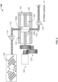
- FIG. 2 is a schematic representation of the first embodiment of the invention in which a linear-actuated drug dosing system 100 comprises two plungers 106a,106b disposed in pump chamber 104.
- Reservoir 102 may contain a quantity of a liquid 103, for example, a drug in liquid form.
- reservoir 102 may be rigid, while, in other embodiments, the reservoir 102 may be flexible and collapsible to eliminate the need for a vent in the reservoir to prevent a vacuum performing therein as liquid 103 is drawn from reservoir 102 into pump chamber 104.
- reservoir 102 may be composed of high-density polyethylene or, in other embodiments, ACLAR ® .
- Reservoir 102 is fluidly coupled to pump chamber 104 through inlet port 113 via inlet conduit 112.
- pump chamber 104 is fluidly coupled to a patient interface through outlet port 117 via outlet conduit 116.
- Inlet conduit 112 and outlet conduit 116 may be composed of, for example, stainless steel or Teflon and may be, for example, tubing of the type of which hypodermic needles are constructed.
- One-way valve 114 prevents liquid 103, which has entered the pump chamber 104, from returning to reservoir 102.
- the patient interface may be, for example, a needle, a needle conduit or tubing that can be used as a fluid path to deliver the liquid 103 to a patient.
- One-way valve 118 prevents fluids from the patient from being drawn into pump chamber 104 as liquid 103 is being drawn into pump chamber 104 from reservoir 102.
- Plungers 106a, 106b are disposed within the pump chamber 104 and may be sealed against the inner surface of sidewall 103 of pump chamber 104.
- the cross-sectional shape of pump chamber 104 may be any shape, including circular; however, in preferred embodiments, the cross-sectional shape of pump chamber 104 may be any one of a number of non-circular shapes, preferred examples of which are shown as reference number 124 in FIG. 2 .
- the non-circular, cross-sectional shape of pump chamber 104 is desirable to prevent plungers 106a, 106b from rotating within pump chamber 104 when leadscrew 108 is rotated. Non-rotation of plungers 106a, 106b is necessary to enable the movement of the plungers 106a, 106b along the longitudinal axis of pump chamber 104 driven by the rotation of leadscrew 108 as it rotates in either direction.
- Leadscrew 108 may be driven by any one of a number of known methods.
- the drive source may be motor 120, which may be coupled to leadscrew 108 via gearing 122.
- Leadscrew 108 is, in this embodiment of the invention, configured with both left-hand and right-hand threads, as shown in the figure.
- rotation of leadscrew 108 in a first direction e.g. clockwise
- plungers 106a, 106b to move toward each other
- an opposite direction e.g. counter-clockwise
- Motor 120 may be coupled to leadscrew 108 via gearing 122.
- gearing 122 may be a planetary gear system, but any configuration of coupling between the motor 120 and leadscrew 108 may be used, including a direct connection.
- Motor 120 may be a continuous motion motor or stepper motor and is preferably controlled by a software-driven controller.
- a nitinol wire drive (not shown) may be used to drive gearing 122 in lieu of motor 120 and may be coupled to leadscrew 108 via gearing 122.
- FIG. 2 shows the device in a static state, with plungers 106a, 106b shown together. This is a likely state of the device just subsequent to the delivery of one or more units of liquid 103 and in ready state for filling of the pump chamber 104 with additional liquid 103 from reservoir 102.
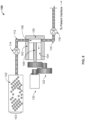
- FIG. 3 is a schematic diagram showing the process of drawing liquid 103 from reservoir 102 into pump chamber 104.
- Motor 120 may be activated in a direction such as to cause plungers 106a, 106b to move away from each other as shown by the arrows in pump chamber 104. Movement of plungers 106a, 106b away from each other causes a negative pressure to form in the volume 104a between the plungers 106a, 106b, which serves to draw liquid 103 through conduit 112, into pump chamber 104 and, more specifically, into volume 104a between plungers 106a, 106b.
- One-way valve 118 prevents fluids from the patient from being drawn through conduit 116 and into volume 104a of pump chamber 104 as plungers 106a, 106b create the negative pressure within volume 104a as they move away from each other.
- Pump chamber 104 may be configured with a vent 107 on end wall 105 of pump chamber 104 to allow air between plunger 106b and end wall 105 of pump chamber 104 to escape as plunger 106b is moved toward end wall 105, and to allow air to enter the space between end wall 105 and plunger 106b when plunger 106b is moved in the opposite direction, away from end wall 105.
- FIG. 4 is a schematic diagram illustrating the process of pumping liquid 103 from volume 104a through conduit 116 to the patient interface.
- Motor 120 may be rotated in a direction opposite the direction of rotation used to draw liquid 103 into volume 104a such as to move plungers 106a, 106b toward each other as shown by the arrows in FIG. 4 , thereby creating a positive pressure within volume 104a.
- the movement of plungers 106a, 106b toward each other reduces the size of volume 104a and forces liquid 103 into the conduit 116 and out to the patient through the patient interface.
- One-way valve 114 prevents liquid 103 from returning to reservoir 102 as plungers 106a, 106b move toward each other, ensuring that all of liquid 103 within volume 104a is forced into conduit 116.
- plungers 106a, 106b Once plungers 106a, 106b have reached a position where they are touching one another, as shown in FIG. 5 , all, or most of liquid 103 within volume 104a will have been forced into conduit 116 to the patient interface. Plungers 106a, 106b do not necessarily need to touch each other to complete a cycle of liquid delivery. However, to reduce the amount of residual liquid within the system, and hence reduce the amount of wasted liquid at the end of usage of system 100, plungers 106a, 106b preferably come into contact at the end of each cycle of liquid delivery, or alternatively, at a final cycle of drug delivery when all or nearly all of liquid drug has been dispensed from reservoir 102.
- plungers 106a, 106b come into contact only at a final cycle of drug delivery will reduce the impact that plungers 106a, 106b have on constituents of the liquid (e.g., molecules of insulin) during each cycle of liquid delivery, thereby prolonging the life or effectiveness of the liquid (e.g., protein molecules within the liquid).
- constituents of the liquid e.g., molecules of insulin
- conduits 112, 116 interface with pump chamber 104 in the volume 104a between plunger 106a, 106b.
- conduits 112 and 116 will connect to volume 104a midway between the largest distance that plunger 106a, 106b can travel from each other, or, in other words, at the point where plungers 106a, 106b meet when they are touching each other or at the end of a cycle, such that when plungers 106a, 106b are in the position shown in FIG. 2 , both inlet port 113 and outlet port 117 are blocked.
- volume 104a may be drawn into volume 104a at a single time and may be dispensed in separate units to the patient. It is not necessary that volume 104a be emptied each time that a unit of liquid 103 is delivered to the patient.
- the quantity of liquid 103 drawn into volume 104a is dependent upon the distance between plungers 106a, 106b at their furthest point of travel away from each other.
- the quantity of liquid 103 drawn into volume 104a can be controlled by varying the distance between plungers 106a, 106b. Larger distances between plungers 106a, 106b will result in a larger volume 104a and, thus, a larger quantity of liquid 103, while smaller distances will result a smaller volume 104a and a smaller quantity of liquid 103 being drawn into volume 104a.
- One advantage of the dual-plunger design is that the system is balanced axially such that it does not induce a thrust onto the bearing support (i.e. the portion where the leadscrew 108 interfaces with end wall 105 of pump chamber 104. This translates into less frictional losses in the system.
- One further advantage is that the design prevents the free flow of liquid 103 directly from reservoir 102 to the patient when plungers 106a, 106 block inlet port 113 and outlet port 117. This can be a safety mechanism in the case of an over-pressure situation or if squeezing of the device forces liquid 103 out of reservoir 102.
- the size of volume 104a may be determined algorithmically by calculation based on the number of turns of leadscrew 108 and the known distance that plungers 106a, 106b travel based on the determined number of turns.
- Other embodiments of determining the size of volume 104a utilizing sensors will now be discussed.
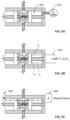
- a gas pressure gauge 601 may be configured to interface with pump chamber 104 through vent 107 in end wall 105. Using air pressure in area 602 as measured by pressure gauge 601, the change in the position of the plungers, and thus changes in the quantity of liquid 103 in volume 104a, can be derived from a measurement of the change in air pressure within area 602. The actual quantity of liquid 103 drawn into volume 104a may be further dependent on other factors, for example, the size of conduit 112.
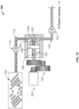
- FIG. 6B shows a second embodiment utilizing a three-segment custom linear encoder using simple analog techniques.
- the position of plunger 106a can thereafter be inferred from the position of plunger 106b.
- FIG. 6C shows yet another embodiment utilizing an ultrasonic sensor.
- An ultrasonic source 606 may direct a beam of ultrasonic sound through vent 107.
- the speed of sound through various media i.e., air ⁇ plastic ⁇ aqueous spolution ⁇ plastic ⁇ air
- a quantity of the liquid 103 can be inferred.
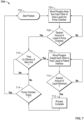
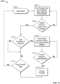
- FIG. 7 shows a flowchart showing process 700 for delivery of liquid 103 from the reservoir 102 to the patient interface.
- the system 100 begins from a start position 702.
- the start position is preferably the position wherein the plungers 106a, 106b are in a touching, face-to-face configuration such that volume 104a is reduced to virtually zero.
- the plungers are moved apart by turning of leadscrew 108 and liquid 103 is drawn from reservoir 102 into the volume 104a between plungers 106a and 106b.
- the determination of whether the desired quantity of liquid 103 has been drawn into volume 104a may be made algorithmically by calculating, for example, the number of turns of leadscrew 108 and its relationship to the size of volume 104a or with the assistance of one of the sensor arrangements shown in FIGS. 6 (A-C), or through the use of any other sensor arrangement.
- control is sent to block 708 and if not, system 100 loops at decision point 716 until triggered.
- the delivery of additional units of liquid 103 could be triggered automatically, for example, by a periodic timer, by manual initiation of the delivery by the patient, or by any other means, such as through an analysis of input received from sensors regarding the current condition of the patient.
- the movement of plungers 106a, 106b toward each other is initiated by rotation of leadscrew 108 in an opposite direction, such as to force a quantity of liquid 103 from volume 104a and into conduit 116, and from there to the patient interface.
- the quantity so far delivered to the patient interface comprises the desired quantity and, if not, control returns to 708, where the plungers continue to move toward each other to push a further quantity of liquid 103 to the patient interface.
- the process is complete at 712.
- volume 104a is empty, that is, the last quantity of liquid 103 has been delivered to the patient. If volume 104a is empty, control returns to start position 702 and the process repeats with the loading of an additional quantity of liquid 103 from reservoir 102 to volume 104a. If volume 104a is not empty, control returns to decision point 716, where the process loops until the delivery of the next unit of liquid 103 is triggered.
- the end position of the plungers when the pump chamber is empty at block 712 is the same as start position at 702, wherein the plungers are in a touching, face-to-face configuration and are thereby ready to draw the next quantity of liquid 103 into volume 104a.
- the second embodiment of the invention has components similar to the first embodiment in configuration and composition and operates in a similar manner. As such, the description of the second embodiment has been condensed for brevity and like reference numerals have been used for like components.
- FIG. 8 is a cross-sectional view of a second embodiment of the pump chamber 104 of the present invention in which only a single plunger 106 is used.
- Rotation of leadscrew 108 in a first direction moves plunger 106 toward end wall 105, while movement of the leadscrew 108 in a second, opposite direction moves plunger 106 away from end wall 105.
- Inlet port 113 and outlet port 117 are preferably located adjacent end wall 105, such that movement of the plunger 106 toward the end wall forces any liquid within the pump chamber 104 into the output conduit 117. Otherwise, the components and materials of the second embodiment of the pump chamber are identical to that of the first embodiment shown in FIG. 1 .
- FIG. 9 is a schematic representation of the second embodiment of the invention in which a linear-actuated drug dosing system 100 comprises a single plunger 106 disposed in pump chamber 104.
- Reservoir 102 is fluidly coupled to pump chamber 104 through inlet port 113 via inlet conduit 112.
- pump chamber 104 is fluidly coupled to a patient interface through outlet port 117 via outlet conduit 116.
- One-way valve 114 prevents liquid 103 which has entered the pump chamber 104, from returning to reservoir 102.
- One-way valve 118 prevents fluids from the patient from being drawn into pump chamber 104 as liquid 103 as being drawn into pump chamber 104 from reservoir 102.
- Plunger 106 is disposed within the pump chamber 104 and may be sealed against the inner surface sidewall 103 of pump chamber 104.
- Leadscrew 108 may be driven by any one of a number of known methods.
- the drive source may be motor 120, which is coupled to leadscrew 108 via gearing 122.
- Leadscrew 108 is, in this embodiment of the invention, configured with a single threading, as shown in the figure.
- Motor 120 may be coupled to leadscrew 108 via gearing 122 to drive leadscrew 108 in either rotational direction.
- FIG. 9 shows the device in a static state, with plunger 106 shown adjacent end wall 105 and blocking inlet port 113 and outlet port 117.
- FIG. 10 is a schematic diagram showing the process of drawing liquid 103 from reservoir 102 into pump chamber 104.
- Motor 120 may be activated in a direction such as to cause plunger 106 to move away from end wall 105 as shown by the arrow in pump chamber 104. Movement of plunger 106 away from end wall 105 causes a negative pressure to form in the volume 104a between the plunger and end wall 105, which serves to draw liquid 103 through conduit 112, into pump chamber 104 and, more specifically, into volume 104a between plunger 106 and end wall 105.
- One-way valve 118 prevents fluids from the patient from being drawn through conduit 116 and into volume 104a as plunger 106 creates the negative pressure within volume 104a as it moves away from end wall 105.
- FIG. 11 is a schematic diagram illustrating the process of pumping liquid 103 from volume 104a through conduit 116 to the patient interface.
- Motor 120 may be rotated in a direction opposite the direction of rotation used to draw liquid 103 into volume 104a such as to move plunger 106 toward end wall 105 as shown by the arrow in FIG. 11 , thereby creating a positive pressure within volume 104a.
- the movement of plunger 106 toward end wall 105 reduces the size of volume 104a and forces liquid 103 into the conduit 116 and out to the patient through the patient interface.
- One-way valve 114 prevents liquid 103 from returning to reservoir 102 as plunger 106 moves toward end wall 105, ensuring that all of liquid 103 within volume 104a is forced into conduit 116.
- plunger 106 Once plunger 106 has reached a position where it is touching end wall 105, as shown in FIG. 12 , all, or most of liquid 103 within volume 104a will have been forced into conduit 116 to the patient interface. Plunger 106 does not necessarily need to touch end wall 105 to complete a cycle of liquid delivery. However, to reduce the amount of residual liquid within the system, and hence reduce the amount of wasted liquid at the end of usage of system 100, plunger 106 preferably comes into contact with end wall 105 at the end of each cycle of liquid delivery, or alternatively, at a final cycle of drug delivery when all or nearly all of liquid drug has been dispensed from reservoir 102.
- plunger 106 come into contact with end wall 105 only at a final cycle of drug delivery will reduce the impact that plunger 106 has on constituents of the liquid (e.g., molecules of insulin) during each cycle of liquid delivery, thereby prolonging the life or effectiveness of the liquid (e.g., protein molecules within the liquid).
- constituents of the liquid e.g., molecules of insulin
- conduits 112, 116 must interface with pump chamber 104 in the volume 104a between plunger 106 and end wall 105. In preferred embodiments of the invention, conduits 112 and 116 will connect to volume 104a directly adjacent end wall 105, such that when plunger 106 is in the position shown in FIG. 12 , both inlet port 113 and outlet port 117 are blocked.
- FIG. 13 shows a flowchart showing process 1300 for delivery of liquid 103 from the reservoir 102 to the patient interface.
- the system 100 begins from a start position 1302.
- the start position is preferably the position wherein plunger 106 is in contact with end wall 105 such that volume 104a is reduced to virtually zero.
- the plunger 106 is moved away from end wall 105 by turning of leadscrew 108 and liquid 103 is drawn from reservoir 102 into the volume 104a between plunger 106 and end wall 105.
- the movement of plunger 106 toward end wall 106 is initiated by rotation of leadscrew 108 in an opposite direction, such as to force a quantity of liquid 103 from volume 104a and into conduit 116, and from there to the patient interface.
- the quantity so far delivered to the patient interface comprises the desired quantity and, if not, control returns to 1308, where the plunger 106 continues to move toward end wall 105 to push a further quantity of liquid 103 to the patient interface.
- the process is complete at 1312.
- control returns to start position 1302 and the process repeats with the loading of an additional quantity of liquid 103 from reservoir 102 to volume 104a. If volume 104a is not empty, control returns to decision point 1316, where the process loops until the delivery the next unit of liquid 103 is triggered.
- the embodiments described herein provide numerous benefits over existing prior art systems. As will be appreciated by a person of ordinary skill in the art, and, in particular with wearable devices, the comfort of the patient can be enhanced by reducing the size of the device.
- the above described embodiments accomplish this by allowing for a pump mechanism having a smaller cross-sectional area and, in addition, utilizing non-circular cross-sectional shapes that could, for instance, be provided as a flattened rectangular shape, thereby reducing the profile of the device.
- the smaller cross-sectional area of the pump mechanism in addition to the fact that only a portion of the quantity of liquid in the reservoir is drawn into the pump chamber at any one time, allows for the use of a smaller, less powerful motor to drive the plungers.
Landscapes
- Health & Medical Sciences (AREA)
- Vascular Medicine (AREA)
- Engineering & Computer Science (AREA)
- Anesthesiology (AREA)
- Biomedical Technology (AREA)
- Heart & Thoracic Surgery (AREA)
- Hematology (AREA)
- Life Sciences & Earth Sciences (AREA)
- Animal Behavior & Ethology (AREA)
- General Health & Medical Sciences (AREA)
- Public Health (AREA)
- Veterinary Medicine (AREA)
- Infusion, Injection, And Reservoir Apparatuses (AREA)
Abstract
Description
- This application claims the benefit of
U.S. Provisional Patent Application No. 63/135,857, filed January 11, 2021 - Many conventional drug delivery systems, including, for example, wearable drug delivery devices, include a drug container, often referred to as a reservoir, that stores a liquid drug. A liquid drug stored in the reservoir may be delivered to the user by expelling the drug from the reservoir using a driven plunger, for example, a leadscrew driven plunger. In present known embodiments, the plunger is typically disposed directly within the reservoir such that the reservoir and the drive comprise a single unit. As result, the reservoir requires a large cross-sectional area, such as to be able to hold the device's entire supply of the drug. The large cross-sectional area has the disadvantage of increasing the minimum dosing increment for a given axial displacement of the plunger. In addition, the larger cross-sectional area requires a larger diameter plunger which leads to more drag and friction on the interior sealing surfaces of the reservoir, thereby increasing the force required to achieve a given pressure and, as a result, requiring a larger, more powerful motor to drive the plunger. A need therefore exists for a configuration which achieves the same effective delivery of the drug, but with a container having a smaller cross-sectional area to overcome the identified deficiencies.
-
-
FIG. 1 is a cross-sectional view of the pump chamber of a first embodiment of the invention in which dual plungers are used. -
FIG. 2 is a schematic view of the pump system of the present invention in a first state in which the pump chamber is empty and the plungers are in a touching, face-to-face configuration. -
FIG. 3 is a schematic view of the pump system of the present invention in a second state in which the plungers have moved away from each other to draw a liquid from the reservoir into the pump chamber. -
FIG. 4 is a schematic view of the pump system of the present invention in a third state in which the plungers are moving toward each other to force the liquid from the pump chamber to the patient interface. -
FIG. 5 is a schematic view of the pump system of the present invention in a fourth state in which all the liquid has been forced from the pump chamber toward the patient interface. -
FIGS. 6 (A-C) show three variations of the pump system of the present invention in which sensors are used to determine the volume of the liquid which has been drawn into the pump chamber. -
FIG. 7 is a flowchart showing the process by which one or multiple units of the liquid are moved from the reservoir to the patient interface. -
FIG. 8 is a cross-sectional view of the pump chamber of a second embodiment of the invention in which a single plunger is used. -
FIG. 9 is a schematic view of the second embodiment of the pump system of the present invention in a first state in which the pump chamber is empty and the plunger is touching the end wall of the pump chamber. -
FIG. 10 is a schematic view of the second embodiment of the pump system of the present invention in a second state in which the plunger has moved away from the end wall to draw a liquid from the reservoir into the pump chamber. -
FIG. 11 is a schematic view of the second embodiment of the pump system of the present invention in a third state in which the plunger is moving toward the end wall to force the liquid from the pump chamber to the patient interface. -
FIG. 12 is a schematic view of the second embodiment of the pump system of the present invention in a fourth state in which all the liquid has been forced from the pump chamber toward the patient interface. -
FIG. 13 is a flowchart showing the process of the second embodiment of the invention in which one or multiple units of the liquid are moved from the reservoir to the patient interface. - This disclosure presents various systems, components and methods for moving a liquid, typically a liquid drug, such as insulin, from a liquid reservoir to a patient interface, typically a needle or cannula. Each of the systems, components and methods disclosed herein provides one or more advantages over conventional, prior art systems components and methods.
- In various embodiments of the invention, the reservoir is separated from the pump chamber but connected thereto via a first conduit having a one-way valve such as to allow flow of the liquid from the reservoir into the pump chamber but not from the pump chamber back into the reservoir. In preferred embodiments of the invention, the reservoir may be a collapsible container; however, in other embodiments, the reservoir may be rigid.
- In one embodiment of the invention, the pump chamber has disposed therein a pair of plungers driven by a leadscrew having both left-hand and right-hand threads such that, when the leadscrew rotates in one direction, the plungers move toward each other and, when the leadscrew is rotated in the opposite direction, the plungers move away from each other.
- The first conduit connecting the pump chamber to the reservoir connects to the pump chamber between the plungers, preferably in the middle of the pump chamber. Thereby, the movement of the plungers away from each other creates a negative pressure in the pump chamber which draws the liquid from the reservoir through the first conduit and into the pump chamber. The leadscrew is thus rotated in a direction such as to move the plungers away from each other to draw the liquid into the pump chamber. The liquid is prevented from returning to the reservoir by the one-way valve disposed in the conduit between the reservoir and the pump chamber.
- Once the pump chamber is filled with an appropriate quantity of the liquid, the leadscrew is rotated in a second, opposite direction, thereby driving the plungers toward each other. A second conduit connected to the pump chamber between the plungers connects the pump chamber to a patient interface, typically a needle. Thus, motion of the plungers toward each other causes a movement of the liquid through the second conduit to the patient. The second conduit is also fitted with a one-way valve such that the suction created by the motion of the plungers away from each other to draw the liquid from the reservoir into the pump chamber does not also draw fluids from the patient through the patient interface and into the pump chamber.
- In a second embodiment of the invention, the pump chamber is fitted with a single plunger driven by a leadscrew. Suction is created to draw the liquid into the pump chamber by motion of the plunger away from a closed end of the pump chamber by rotation of the leadscrew in a first direction. In this embodiment, it can be seen that the first conduit connecting the reservoir to the pump chamber must be connected to the pump chamber near, if not directly adjacent to or through, the closed end of the pump chamber.
- The liquid is then pushed out to the second conduit to the patient interface by motion of the plunger toward the closed end, caused by rotation of the leadscrew in the opposite direction. It should also be realized that the second conduit connecting the pump chamber to the patient interface must be connected to the pump chamber near or through the closed end. In the second embodiment of the invention, both the first and second conduits are also fitted with a one-way valve so as to prevent the liquid in the pump chamber from returning to the reservoir and to prevent fluids from the patient from entering the pump chamber.
- In one embodiment of the invention, the rotation of the leadscrew can be driven by a drive coupled to the leadscrew either directly or via gearing.
- The improved liquid delivery system disclosed herein thus addresses the problems identified in the Background section. By separating the reservoir from the pump chamber, the pump chamber can be configured with a cross-sectional area of any size, preferably small enough to overcome the difficulties associated with the larger diameter cross-sectional areas of conventional, prior art devices.
-
FIG. 1 is a cross-sectional view of a first embodiment of thepump chamber 104 of the present invention.Pump chamber 104 consists of an open-endedcontainer comprising sidewall 103 andendcap 105.Sidewall 103 may comprise a tube-like structure having a cross-sectional shape. In some instances,sidewall 103 andendcap 105 may be formed as an integral unit, however, in other instances,sidewall 103 andendcap 105 may be formed separately and joined together.Sidewall 103 andendcap 105 may be composed of, for example, glass, polypropylene or any other bio- or drug-compatible material. In certain embodiments,endcap 105 may be absent, withpump chamber 104 being open at both ends. -
Sidewall 103 has formed thereininlet port 113 andoutlet port 117.Inlet port 113 may connect, via a conduit, to a reservoir which may hold a quantity of a liquid.Outlet port 117 may connect to a patient interface for delivery of the liquid to a patient. Preferably,inlet port 113 andoutlet port 117 will be located midway betweenplungers plungers inlet port 113 andoutlet port 117 are fully or partially blocked. This serves as a safety feature to prevent free-flow of the liquid from the reservoir to the patient interface in the event of valve failure. In preferred embodiments of the invention,inlet port 113 andoutlet port 117 are located opposite each other alongsidewall 103; however, in other embodiments,inlet port 113 andoutlet port 117 may be positioned at any convenient location alongsidewall 103. - Disposed within
pump chamber 104 areplungers plungers plungers plungers plungers plungers plungers plungers -
Plungers leadscrew 108. In certain embodiments,leadscrew 108 may be composed of stainless steel, polypropylene, or any other well-known bio- or drug-compatible material. In preferred embodiments,leadscrew 108 comprises both left-handed threading 101a and right-handed threading 101b as an interface withplungers leadscrew 108 in a first direction will causeplungers pump chamber 104 until touching, and such that rotation ofleadscrew 108 in a second, opposite direction will causeplungers pump chamber 104. -
FIG. 2 is a schematic representation of the first embodiment of the invention in which a linear-actuateddrug dosing system 100 comprises twoplungers pump chamber 104.Reservoir 102 may contain a quantity of a liquid 103, for example, a drug in liquid form. In some embodiments of the invention,reservoir 102 may be rigid, while, in other embodiments, thereservoir 102 may be flexible and collapsible to eliminate the need for a vent in the reservoir to prevent a vacuum performing therein asliquid 103 is drawn fromreservoir 102 intopump chamber 104. In some embodiments,reservoir 102 may be composed of high-density polyethylene or, in other embodiments, ACLAR®. -
Reservoir 102 is fluidly coupled to pumpchamber 104 throughinlet port 113 viainlet conduit 112. Likewise, pumpchamber 104 is fluidly coupled to a patient interface throughoutlet port 117 viaoutlet conduit 116.Inlet conduit 112 andoutlet conduit 116 may be composed of, for example, stainless steel or Teflon and may be, for example, tubing of the type of which hypodermic needles are constructed. One-way valve 114 prevents liquid 103, which has entered thepump chamber 104, from returning toreservoir 102. The patient interface may be, for example, a needle, a needle conduit or tubing that can be used as a fluid path to deliver the liquid 103 to a patient. One-way valve 118 prevents fluids from the patient from being drawn intopump chamber 104 asliquid 103 is being drawn intopump chamber 104 fromreservoir 102. -
Plungers pump chamber 104 and may be sealed against the inner surface ofsidewall 103 ofpump chamber 104. It should be noted that the cross-sectional shape ofpump chamber 104 may be any shape, including circular; however, in preferred embodiments, the cross-sectional shape ofpump chamber 104 may be any one of a number of non-circular shapes, preferred examples of which are shown asreference number 124 inFIG. 2 . The non-circular, cross-sectional shape ofpump chamber 104 is desirable to preventplungers pump chamber 104 when leadscrew 108 is rotated. Non-rotation ofplungers plungers pump chamber 104 driven by the rotation ofleadscrew 108 as it rotates in either direction. -
Leadscrew 108 may be driven by any one of a number of known methods. In one embodiment, the drive source may bemotor 120, which may be coupled toleadscrew 108 viagearing 122.Leadscrew 108 is, in this embodiment of the invention, configured with both left-hand and right-hand threads, as shown in the figure. Thus, rotation ofleadscrew 108 in a first direction (e.g. clockwise) will causeplungers leadscrew 108 in an opposite direction (e.g. counter-clockwise) will causeplungers -
Motor 120 may be coupled toleadscrew 108 viagearing 122. In some embodiments of the invention, gearing 122 may be a planetary gear system, but any configuration of coupling between themotor 120 andleadscrew 108 may be used, including a direct connection.Motor 120 may be a continuous motion motor or stepper motor and is preferably controlled by a software-driven controller. - In alternate embodiments of the invention, a nitinol wire drive (not shown) may be used to drive gearing 122 in lieu of
motor 120 and may be coupled toleadscrew 108 viagearing 122. -
FIG. 2 shows the device in a static state, withplungers liquid 103 and in ready state for filling of thepump chamber 104 with additional liquid 103 fromreservoir 102. -
FIG. 3 is a schematic diagram showing the process of drawing liquid 103 fromreservoir 102 intopump chamber 104.Motor 120 may be activated in a direction such as to causeplungers pump chamber 104. Movement ofplungers volume 104a between theplungers conduit 112, intopump chamber 104 and, more specifically, intovolume 104a betweenplungers way valve 118 prevents fluids from the patient from being drawn throughconduit 116 and intovolume 104a ofpump chamber 104 asplungers volume 104a as they move away from each other. -
Pump chamber 104 may be configured with avent 107 onend wall 105 ofpump chamber 104 to allow air betweenplunger 106b andend wall 105 ofpump chamber 104 to escape asplunger 106b is moved towardend wall 105, and to allow air to enter the space betweenend wall 105 andplunger 106b whenplunger 106b is moved in the opposite direction, away fromend wall 105. -
FIG. 4 is a schematic diagram illustrating the process of pumping liquid 103 fromvolume 104a throughconduit 116 to the patient interface.Motor 120 may be rotated in a direction opposite the direction of rotation used to draw liquid 103 intovolume 104a such as to moveplungers FIG. 4 , thereby creating a positive pressure withinvolume 104a. The movement ofplungers volume 104a and forces liquid 103 into theconduit 116 and out to the patient through the patient interface. One-way valve 114 prevents liquid 103 from returning toreservoir 102 asplungers liquid 103 withinvolume 104a is forced intoconduit 116. - Once
plungers FIG. 5 , all, or most ofliquid 103 withinvolume 104a will have been forced intoconduit 116 to the patient interface.Plungers system 100,plungers reservoir 102. Havingplungers plungers - It should be noted that
conduits pump chamber 104 in thevolume 104a between plunger 106a, 106b. In preferred embodiments of the invention,conduits volume 104a midway between the largest distance that plunger 106a, 106b can travel from each other, or, in other words, at the point whereplungers plungers FIG. 2 , bothinlet port 113 andoutlet port 117 are blocked. - It should be noted that multiple units of
liquid 103 may be drawn intovolume 104a at a single time and may be dispensed in separate units to the patient. It is not necessary thatvolume 104a be emptied each time that a unit ofliquid 103 is delivered to the patient. - It should be further noted that the quantity of
liquid 103 drawn intovolume 104a is dependent upon the distance betweenplungers liquid 103 drawn intovolume 104a can be controlled by varying the distance betweenplungers plungers larger volume 104a and, thus, a larger quantity ofliquid 103, while smaller distances will result asmaller volume 104a and a smaller quantity ofliquid 103 being drawn intovolume 104a. - One advantage of the dual-plunger design is that the system is balanced axially such that it does not induce a thrust onto the bearing support (i.e. the portion where the
leadscrew 108 interfaces withend wall 105 ofpump chamber 104. This translates into less frictional losses in the system. One further advantage is that the design prevents the free flow ofliquid 103 directly fromreservoir 102 to the patient whenplungers block inlet port 113 andoutlet port 117. This can be a safety mechanism in the case of an over-pressure situation or if squeezing of the device forces liquid 103 out ofreservoir 102. - Various other methods are possible in this embodiment of the invention for measuring the size of the
volume 104a betweenplungers liquid 103 which is drawn intovolume 104a. In one embodiment of the invention, the size ofvolume 104a may be determined algorithmically by calculation based on the number of turns ofleadscrew 108 and the known distance thatplungers volume 104a utilizing sensors will now be discussed. -
FIG. 6A shows one embodiment using a pressure gauge to calculate a volume change in thepump chamber 104 using the ideal gas law equation PV = nRT. Agas pressure gauge 601 may be configured to interface withpump chamber 104 throughvent 107 inend wall 105. Using air pressure inarea 602 as measured bypressure gauge 601, the change in the position of the plungers, and thus changes in the quantity ofliquid 103 involume 104a, can be derived from a measurement of the change in air pressure withinarea 602. The actual quantity ofliquid 103 drawn intovolume 104a may be further dependent on other factors, for example, the size ofconduit 112. -
FIG. 6B shows a second embodiment utilizing a three-segment custom linear encoder using simple analog techniques. In this embodiment, change in the length (length = l1 + l 2 + l 3) of conductive bar orwire 604 can alter its resistance / current and can be calibrated to the position ofplunger 106b. The position of plunger 106a can thereafter be inferred from the position ofplunger 106b. -
FIG. 6C shows yet another embodiment utilizing an ultrasonic sensor. Anultrasonic source 606 may direct a beam of ultrasonic sound throughvent 107. The speed of sound through various media (i.e., air → plastic → aqueous spolution → plastic → air) is known and, as such, based on timing, with the known distance between theultrasonic source 606 and anultrasonic detector 608, a quantity of the liquid 103 can be inferred. -
FIG. 7 shows aflowchart showing process 700 for delivery ofliquid 103 from thereservoir 102 to the patient interface. Thesystem 100 begins from astart position 702. The start position is preferably the position wherein theplungers volume 104a is reduced to virtually zero. - At
block 704, the plungers are moved apart by turning ofleadscrew 108 and liquid 103 is drawn fromreservoir 102 into thevolume 104a betweenplungers block 706, it is determined whether the desired quantity ofliquid 103 has been drawn intovolume 104a ofpump chamber 104 and, if not, control is returned to block 704, where theplungers liquid 103 is present involume 104a. The determination of whether the desired quantity ofliquid 103 has been drawn intovolume 104a may be made algorithmically by calculating, for example, the number of turns ofleadscrew 108 and its relationship to the size ofvolume 104a or with the assistance of one of the sensor arrangements shown inFIGS. 6 (A-C), or through the use of any other sensor arrangement. - At
block 716 it is determined if it is time for the delivery of the additional units ofliquid 103 to the patient. If so, control is sent to block 708 and if not,system 100 loops atdecision point 716 until triggered. The delivery of additional units ofliquid 103 could be triggered automatically, for example, by a periodic timer, by manual initiation of the delivery by the patient, or by any other means, such as through an analysis of input received from sensors regarding the current condition of the patient. - At
block 708, the movement ofplungers leadscrew 108 in an opposite direction, such as to force a quantity ofliquid 103 fromvolume 104a and intoconduit 116, and from there to the patient interface. At 710 it is determined if the quantity so far delivered to the patient interface comprises the desired quantity and, if not, control returns to 708, where the plungers continue to move toward each other to push a further quantity ofliquid 103 to the patient interface. At 710, if the desired quantity ofliquid 103 has been delivered to the patient interface, the process is complete at 712. - At
decision point 714, it is determined if thevolume 104a is empty, that is, the last quantity ofliquid 103 has been delivered to the patient. Ifvolume 104a is empty, control returns to startposition 702 and the process repeats with the loading of an additional quantity ofliquid 103 fromreservoir 102 tovolume 104a. Ifvolume 104a is not empty, control returns todecision point 716, where the process loops until the delivery of the next unit ofliquid 103 is triggered. - Note that the end position of the plungers when the pump chamber is empty at
block 712 is the same as start position at 702, wherein the plungers are in a touching, face-to-face configuration and are thereby ready to draw the next quantity ofliquid 103 intovolume 104a. - The second embodiment of the invention has components similar to the first embodiment in configuration and composition and operates in a similar manner. As such, the description of the second embodiment has been condensed for brevity and like reference numerals have been used for like components.
-
FIG. 8 is a cross-sectional view of a second embodiment of thepump chamber 104 of the present invention in which only asingle plunger 106 is used. Rotation ofleadscrew 108 in a first direction movesplunger 106 towardend wall 105, while movement of theleadscrew 108 in a second, opposite direction movesplunger 106 away fromend wall 105.Inlet port 113 andoutlet port 117 are preferably locatedadjacent end wall 105, such that movement of theplunger 106 toward the end wall forces any liquid within thepump chamber 104 into theoutput conduit 117. Otherwise, the components and materials of the second embodiment of the pump chamber are identical to that of the first embodiment shown inFIG. 1 . -
FIG. 9 is a schematic representation of the second embodiment of the invention in which a linear-actuateddrug dosing system 100 comprises asingle plunger 106 disposed inpump chamber 104. -
Reservoir 102 is fluidly coupled to pumpchamber 104 throughinlet port 113 viainlet conduit 112. Likewise, pumpchamber 104 is fluidly coupled to a patient interface throughoutlet port 117 viaoutlet conduit 116. One-way valve 114 prevents liquid 103 which has entered thepump chamber 104, from returning toreservoir 102. One-way valve 118 prevents fluids from the patient from being drawn intopump chamber 104 asliquid 103 as being drawn intopump chamber 104 fromreservoir 102. -
Plunger 106 is disposed within thepump chamber 104 and may be sealed against theinner surface sidewall 103 ofpump chamber 104.Leadscrew 108 may be driven by any one of a number of known methods. In one embodiment, the drive source may bemotor 120, which is coupled toleadscrew 108 viagearing 122.Leadscrew 108 is, in this embodiment of the invention, configured with a single threading, as shown in the figure. Thus, rotation ofleadscrew 108 in a first direction (e.g. clockwise) will causeplunger 106 to move towardend wall 105, while rotation ofleadscrew 108 in an opposite direction (e.g. counter-clockwise) will causeplunger 106 to move away fromend wall 105. -
Motor 120 may be coupled toleadscrew 108 via gearing 122 to drive leadscrew 108 in either rotational direction. -
FIG. 9 shows the device in a static state, withplunger 106 shownadjacent end wall 105 and blockinginlet port 113 andoutlet port 117. -
FIG. 10 is a schematic diagram showing the process of drawing liquid 103 fromreservoir 102 intopump chamber 104.Motor 120 may be activated in a direction such as to causeplunger 106 to move away fromend wall 105 as shown by the arrow inpump chamber 104. Movement ofplunger 106 away fromend wall 105 causes a negative pressure to form in thevolume 104a between the plunger andend wall 105, which serves to draw liquid 103 throughconduit 112, intopump chamber 104 and, more specifically, intovolume 104a betweenplunger 106 andend wall 105. One-way valve 118 prevents fluids from the patient from being drawn throughconduit 116 and intovolume 104a asplunger 106 creates the negative pressure withinvolume 104a as it moves away fromend wall 105. -
FIG. 11 is a schematic diagram illustrating the process of pumping liquid 103 fromvolume 104a throughconduit 116 to the patient interface.Motor 120 may be rotated in a direction opposite the direction of rotation used to draw liquid 103 intovolume 104a such as to moveplunger 106 towardend wall 105 as shown by the arrow inFIG. 11 , thereby creating a positive pressure withinvolume 104a. The movement ofplunger 106 towardend wall 105 reduces the size ofvolume 104a and forces liquid 103 into theconduit 116 and out to the patient through the patient interface. One-way valve 114 prevents liquid 103 from returning toreservoir 102 asplunger 106 moves towardend wall 105, ensuring that all ofliquid 103 withinvolume 104a is forced intoconduit 116. - Once
plunger 106 has reached a position where it is touchingend wall 105, as shown inFIG. 12 , all, or most ofliquid 103 withinvolume 104a will have been forced intoconduit 116 to the patient interface.Plunger 106 does not necessarily need to touchend wall 105 to complete a cycle of liquid delivery. However, to reduce the amount of residual liquid within the system, and hence reduce the amount of wasted liquid at the end of usage ofsystem 100,plunger 106 preferably comes into contact withend wall 105 at the end of each cycle of liquid delivery, or alternatively, at a final cycle of drug delivery when all or nearly all of liquid drug has been dispensed fromreservoir 102. Havingplunger 106 come into contact withend wall 105 only at a final cycle of drug delivery will reduce the impact that plunger 106 has on constituents of the liquid (e.g., molecules of insulin) during each cycle of liquid delivery, thereby prolonging the life or effectiveness of the liquid (e.g., protein molecules within the liquid). - It should be noted that
conduits pump chamber 104 in thevolume 104a betweenplunger 106 andend wall 105. In preferred embodiments of the invention,conduits volume 104a directlyadjacent end wall 105, such that whenplunger 106 is in the position shown inFIG. 12 , bothinlet port 113 andoutlet port 117 are blocked. -
FIG. 13 shows aflowchart showing process 1300 for delivery ofliquid 103 from thereservoir 102 to the patient interface. Thesystem 100 begins from astart position 1302. The start position is preferably the position whereinplunger 106 is in contact withend wall 105 such thatvolume 104a is reduced to virtually zero. - At
block 1304, theplunger 106 is moved away fromend wall 105 by turning ofleadscrew 108 and liquid 103 is drawn fromreservoir 102 into thevolume 104a betweenplunger 106 andend wall 105. Atblock 1306, it is determined whether the desired quantity ofliquid 103 has been drawn intovolume 104a and, if not, control is returned to block 1304, where theplunger 106 continues to move away fromend wall 105 until the desired quantity ofliquid 103 is present involume 104a. - At
block 1316 it is determined if it is time for the delivery of the additional units ofliquid 103 to the patient. If so, control is sent to block 1308 and if not,system 100 loops atdecision point 1316 until triggered. - At
block 1308, the movement ofplunger 106 towardend wall 106 is initiated by rotation ofleadscrew 108 in an opposite direction, such as to force a quantity ofliquid 103 fromvolume 104a and intoconduit 116, and from there to the patient interface. At 1310 it is determined if the quantity so far delivered to the patient interface comprises the desired quantity and, if not, control returns to 1308, where theplunger 106 continues to move towardend wall 105 to push a further quantity ofliquid 103 to the patient interface. At 1310, if the desired quantity ofliquid 103 has been delivered to the patient interface, the process is complete at 1312. - At
decision point 1314, it is determined if thevolume 104a is empty and, if so, control returns to startposition 1302 and the process repeats with the loading of an additional quantity ofliquid 103 fromreservoir 102 tovolume 104a. Ifvolume 104a is not empty, control returns todecision point 1316, where the process loops until the delivery the next unit ofliquid 103 is triggered. - The embodiments described herein provide numerous benefits over existing prior art systems. As will be appreciated by a person of ordinary skill in the art, and, in particular with wearable devices, the comfort of the patient can be enhanced by reducing the size of the device. The above described embodiments accomplish this by allowing for a pump mechanism having a smaller cross-sectional area and, in addition, utilizing non-circular cross-sectional shapes that could, for instance, be provided as a flattened rectangular shape, thereby reducing the profile of the device. In addition, the smaller cross-sectional area of the pump mechanism, in addition to the fact that only a portion of the quantity of liquid in the reservoir is drawn into the pump chamber at any one time, allows for the use of a smaller, less powerful motor to drive the plungers.
- The following examples pertain to further embodiments:
- Example 1 is a pump system comprising a pump chamber, a leadscrew having both left-hand threading and right-hand threading disposed along the longitudinal axis of the pump chamber and two plungers coupled to the leadscrew such that rotation of the leadscrew in a first direction causes the plungers to move together and a rotation of the leadscrew in the other direction causes the plungers to move apart.
- Example 2 is an extension of Example 1, or any other example disclosed herein, wherein the pump chamber has a non-circular cross-sectional shape.
- Example 3 is an extension of Example 1, or any other example disclosed herein, wherein the pump chamber is configured with an inlet port and an outlet port.
- Example 4 is an extension of Example 3, or any other example disclosed herein, wherein the inlet port and an outlet port are located in an area of the sidewall between the two plungers.
- Example 5 is an extension of Example 4 or any other example disclosed herein, in which the pump system further comprises a reservoir connected to the pump chamber through the inlet conduit connected to the input port of the pump chamber, and a one-way valve disposed between the reservoir and the pump chamber which allows fluid flow in a direction from the reservoir into the pump chamber but not in the reverse direction.
- Example 6 is an extension of Example 5, or any other example disclosed herein, wherein the reservoir is collapsible.
- Example 7 is an extension of Example 5, or any other example disclosed herein, wherein the pump system further comprises a patient interface connected to the pump chamber through an outlet conduit connected to the outlet port of the pump chamber and a one-way valve allowing fluid to flow in a direction from the pump chamber to the patient interface but not in the reverse direction.
- Example 8 is an extension of Example 7, or any other example disclosed herein, wherein the movement of the plungers away from each other causes a negative pressure in the space between the plungers, thereby drawing liquid in the reservoir into the pump chamber.
- Example 9 is an extension of Example 8, or any other example disclosed herein, wherein movement of the plungers toward each other causes a positive pressure in the space between the plungers, thereby forcing liquid in the pump chamber into the outlet conduit.
- Example 10 is an extension of Example 9, or any other example disclosed herein, wherein the volume of the space between the first and second plungers is algorithmically determined based on the number of turns of the leadscrew.
- Example 11 is an extension of Example 9, or any other example disclosed herein, wherein the volume of the space between the first and second plungers is algorithmically determined based on input from a sensor.
- Example 12 is an extension of Example 9, or any other example disclosed herein, wherein a quantity of a liquid disposed in the reservoir is drawn into the pump chamber as the plungers move away from each other.
- Example 13 is an extension of Example 9, or any other example disclosed herein, wherein a single unit of the liquid may be forced into the patient interface by movement of the plungers such as to reduce the volume of the space therebetween by a predetermined amount corresponding to a single unit of the liquid.
- Example 14 is an extension of Example 1, or any other example disclosed herein, wherein the pump system further comprises a drive for rotating the leadscrew in either direction.
- Example 15 is extension of Example 14, or any other example disclosed herein, wherein the drive comprises a motor coupled to the leadscrew via one or more gears.
- Example 16 is a method comprising moving two plungers away from each other within the pump chamber to draw a quantity of a liquid into the pump chamber and moving the plungers toward each other to deliver a desired quantity of the liquid to a patient interface.
- Example 17 is an extension of the Example of 16, or any other example disclosed herein, wherein the liquid is stored in an external reservoir which is coupled to the pump chamber via an inlet conduit having a one-way valve to prevent the liquid from moving from the pump chamber to the reservoir.
- Example 18 is an extension of Example 18, or any other example disclosed herein, wherein the patient interface is coupled to the pump chamber via an outlet conduit configured with a one-way valve to prevent fluids from moving from the outlet conduit into the pump chamber.
- Example 19 is an extension of Example 17, or any other example disclosed herein, wherein the first and second plungers are coupled to a leadscrew having both left-hand and right-hand threading and wherein rotation the leadscrew in a first direction causes the plungers to move toward each other and in a second, opposite direction causes the plungers to move away from each other and further wherein the leadscrew is coupled to a motor to drive the leadscrew in either direction.
- Example 20 is a pump system which comprises a pump chamber, a threaded leadscrew extending along a longitudinal axis of the pump chamber, a plunger coupled to the leadscrew, an inlet port coupled to a reservoir and an outlet port coupled to a patient interface, wherein rotation of the leadscrew causes the plunger to move away from the closed end of the pump chamber to draw liquid from the reservoir into the pump chamber and rotation of the leadscrew in a second, opposite direction causes the plunger to move toward the closed end of the pump chamber thereby forcing the liquid from the pump chamber to the patient interface.
- Certain embodiments of the present invention were described above. It is, however, expressly noted that the present invention is not limited to those embodiments, but rather it is intended that additions and modifications to the expressly described embodiments herein are also to be included within the scope of the invention. Moreover, it is to be understood that the features of the various embodiments described herein were not mutually exclusive and can exist in various combinations and permutations, even if such combinations or permutations were not made express herein, without departing from the spirit and scope of the invention. In fact, variations, modifications, and other implementations of what was described herein will occur to those of ordinary skill in the art without departing from the spirit and the scope of the invention. As such, the invention is not to be defined only by the preceding illustrative description. Future filed applications claiming priority to this application may claim the disclosed subject matter in a different manner and may generally include any set of one or more limitations as variously disclosed or otherwise demonstrated herein.
- Although the present invention is defined in the attached claims, it should be understood that the present invention can also (alternatively) be defined in accordance with the following embodiments:
- 1. A pump system comprising:
- a pump chamber comprising a tube-like structure, at least one end of the pump chamber being open-ended;
- a leadscrew, extending along a longitudinal axis of the pump chamber, the leadscrew having left-hand and right-hand threads defined thereon;
- a first plunger coupled to the leadscrew via the left-hand threads; and
- a second plunger, coupled to the leadscrew via the right-hand threads;
- wherein rotation of the leadscrew in a first direction causes the first and second plungers to move toward each other and further wherein rotation of the leadscrew in a second,
- opposite direction causes the first and second plungers to move away from each other.
- 2. The pump system of embodiment 1, wherein the pump chamber has a non-circular cross-sectional shape.
- 3. The pump system of embodiment 1, further comprising:
- an inlet port, defined in a sidewall of the pump chamber; and
- an outlet port, defined in the sidewall of the pump chamber.
- 4. The pump system of embodiment 3 wherein the inlet port and outlet port are located in an area of the sidewall between the first and second plungers.
- 5. The pump system of embodiment 4 further comprising:
- an inlet conduit coupled to the inlet port;
- a reservoir, in fluid communication with the pump chamber via the inlet conduit; and an inlet one-way valve, disposed between the reservoir and the pump chamber,
- the one-way valve allowing fluid to flow from the reservoir into the pump chamber and preventing fluid from flowing from the pump chamber to the reservoir.
- 6. The pump system of embodiment 5 wherein the reservoir is collapsible.
- 7. The pump system of embodiment 5, further comprising:
- an outlet conduit, coupled to the outlet port;
- a patient interface, in fluid communication with the pump chamber via the outlet conduit; and
- an outlet one-way valve, disposed between the pump chamber and the patient interface, the one-way valve allowing fluid to flow from the pump chamber to the patient interface and preventing fluid from flowing from the patient interface to the pump chamber.
- 8. The pump system of embodiment 7, wherein movement of the plungers away from each other causes a negative pressure in a space between the plungers within the pump chamber, the negative pressure drawing a liquid disposed in the reservoir into the pump chamber through the inlet conduit.
- 9. The pump system of embodiment 8 where movement of the plungers toward each other causes a positive pressure in the space between the plungers within the pump chamber, the positive pressure forcing the liquid in the pump chamber into the outlet conduit.
- 10. The pump system of embodiment 9 wherein the volume of the space between the first and second plungers can be algorithmically determined based on the number of turns of the leadscrew.
- 11. The pump system of embodiment 9 wherein the volume of the space between the first and second plungers can be algorithmically determined based on input from one or more sensors.
- 12. The pump system of embodiment 9 wherein one or more units of the liquid may be drawn into the reservoir as the plungers move away from each other.
- 13. The pump system of embodiment 9 wherein a single unit of the liquid may be sent to the patient interface by movement of the first and second plungers to reduce the volume of the space between the first and second plungers by a predetermined amount corresponding to the single unit of the liquid.
- 14. The pump system of embodiment 1 further comprising:
a drive, coupled to the leadscrew, for rotating the leadscrew in the first and second directions. - 15. The pump system of embodiment 14 wherein the drive comprises a motor coupled to the leadscrew via one or more gears.
- 16. A method comprising:
- moving a first and second plunger away from each other within a pump chamber to create a negative pressure between the first and second plungers to draw one or more units of a liquid into a pump chamber; and
- moving the first and second plungers toward each other by a predetermined amount to deliver a desired volume of the liquid to a patient interface.
- 17. The method of embodiment 16, wherein:
- the liquid is stored in a reservoir external from the pump chamber;
- the reservoir is coupled to the pump chamber via an inlet conduit; and
- the inlet conduit is configured with a one-way valve to prevent the liquid from moving from the pump chamber to the reservoir.
- 18. The method of embodiment 17, wherein:
- the patient interface is coupled to the pump chamber via an outlet conduit; and
- the outlet conduit is configured with a one-way valve to prevent fluids from entering the pump chamber from the patient interface.
- 19. The method of embodiment 17, wherein:
- the first and second plungers are coupled to a leadscrew with a portion having left-hand threading and a portion having right-hand threading;
- rotation of the leadscrew in a first direction causes the first and second plungers to move toward each other;
- rotation of the leadscrew in a second, opposite direction causes the first and second plungers to move away from each other; and
- the leadscrew is coupled to a motor to drive the leadscrew in the first and second directions.
- 20. A pump system comprising:
- a pump chamber comprising a tube-like structure open at one end and closed at an opposite end;
- a threaded leadscrew, extending along a longitudinal axis of the pump chamber;
- a plunger coupled to the leadscrew via the threading;
- an inlet port fluidly coupled to a reservoir; and
- an outlet port fluidly coupled to a patient interface;
- wherein rotation of the leadscrew causes the plunger to move away from the closed and of the pump chamber, thereby drawing a liquid from the reservoir into the pump chamber; and
- wherein rotation of the leadscrew in a second, opposite direction causes the plunger to move toward the closed end of the pump chamber, thereby forcing the liquid from the pump chamber to the patient interface.
- Although the present invention is defined in the attached claims, it should be understood that the present invention can also (alternatively) be defined in accordance with the following embodiments:
- 1. A pump system comprising:
- a pump chamber comprising a tube-like structure, at least one end of the pump chamber being open-ended;
- a leadscrew, extending along a longitudinal axis of the pump chamber, the leadscrew having left-hand and right-hand threads defined thereon;
- a first plunger coupled to the leadscrew via the left-hand threads; and
- a second plunger, coupled to the leadscrew via the right-hand threads;
- wherein rotation of the leadscrew in a first direction causes the first and second plungers to move toward each other and further wherein rotation of the leadscrew in a second, opposite direction causes the first and second plungers to move away from each other.
- 2. The pump system of embodiment 1, wherein the pump chamber has a non-circular cross-sectional shape.
- 3. The pump system of embodiment 1, further comprising:
- an inlet port, defined in a sidewall of the pump chamber; and
- an outlet port, defined in the sidewall of the pump chamber.
- 4. The pump system of embodiment 3 wherein the inlet port and outlet port are located in an area of the sidewall between the first and second plungers.
- 5. The pump system of embodiment 4 further comprising:
- an inlet conduit coupled to the inlet port;
- a reservoir, in fluid communication with the pump chamber via the inlet conduit; and
- an inlet one-way valve, disposed between the reservoir and the pump chamber, the one-way valve allowing fluid to flow from the reservoir into the pump chamber and preventing fluid from flowing from the pump chamber to the reservoir.
- 6. The pump system of embodiment 5 wherein the reservoir is collapsible.
- 7. The pump system of embodiment 5, further comprising:
- an outlet conduit, coupled to the outlet port;
- a patient interface, in fluid communication with the pump chamber via the outlet conduit; and
- an outlet one-way valve, disposed between the pump chamber and the patient interface, the one-way valve allowing fluid to flow from the pump chamber to the patient interface and preventing fluid from flowing from the patient interface to the pump chamber.
- 8. The pump system of embodiment 7, wherein movement of the plungers away from each other causes a negative pressure in a space between the plungers within the pump chamber, the negative pressure drawing a liquid disposed in the reservoir into the pump chamber through the inlet conduit.
- 9. The pump system of embodiment 8 where movement of the plungers toward each other causes a positive pressure in the space between the plungers within the pump chamber, the positive pressure forcing the liquid in the pump chamber into the outlet conduit.
- 10. The pump system of embodiment 9 wherein the volume of the space between the first and second plungers can be algorithmically determined based on the number of turns of the leadscrew.
- 11. The pump system of embodiment 9 wherein the volume of the space between the first and second plungers can be algorithmically determined based on input from one or more sensors.
- 12. The pump system of embodiment 9 wherein one or more units of the liquid may be drawn into the reservoir as the plungers move away from each other.
- 13. The pump system of embodiment 9 wherein a single unit of the liquid may be sent to the patient interface by movement of the first and second plungers to reduce the volume of the space between the first and second plungers by a predetermined amount corresponding to the single unit of the liquid.
- 14. The pump system of embodiment 1 further comprising:
a drive, coupled to the leadscrew, for rotating the leadscrew in the first and second directions. - 15. The pump system of embodiment 14 wherein the drive comprises a motor coupled to the leadscrew via one or more gears.
Claims (12)
- A pump system (100) comprising:a pump chamber (104) comprising a tube-like structure open at one end and closed at an opposite end (105);a threaded leadscrew (108), extending along a longitudinal axis of the pump chamber (104);a plunger (106) coupled to the leadscrew (108) via the threading;an inlet port (113) fluidly coupled to a reservoir (102); andan outlet port (117) fluidly coupled to a patient interface;wherein rotation of the leadscrew (108) causes the plunger (106) to move away from the closed end (105) of the pump chamber (104), thereby drawing a liquid from the reservoir (102) into the pump chamber (104); andwherein rotation of the leadscrew (108) in a second, opposite direction causes the plunger (106) to move toward the closed end (105) of the pump chamber (104), thereby forcing the liquid from the pump chamber (104) to the patient interface.
- The pump system (100) of claim 1, wherein moving the plunger away from the closed end of the pump chamber (104) causes a negative pressure to form in a volume (104a) between the plunger (106) and the closed end (105) of the pump chamber.
- The pump system (100) of claim 2, wherein the reservoir (102) is fluidly coupled to pump chamber (104) through inlet port (113) via inlet conduit (112) and pump chamber (104) is fluidly coupled to the patient interface through outlet port (117) via outlet conduit (116),
wherein the inlet conduit (112) and the outlet conduit (116) interface with the pump chamber (104) in the volume (104a). - The pump system (100) of any of claims 2 or 3, further comprising a one-way valve (118) configured to prevent fluids from a patient from being drawn into the volume.
- The pump system (100) of any of the preceding claims, wherein the plunger (106) is configured so that the plunger (106) comes into contact with the closed end (105) of the pump chamber (104) at an end of each cycle of liquid delivery.
- The pump system (100) of any of claims 1-3, wherein the plunger (106) is configured so that the plunger (106) comes into contact with the closed end (105) of the pump chamber (104) at an end of a final cycle of liquid delivery.
- The pump system (100) of any of the preceding claims, wherein the inlet conduit (112) and outlet conduit (116) are directly adjacent to the closed end (105) of the pump chamber (104) so that when the plunger (106) is in a position touching the closed end of the pump chamber (104), the inlet port (113) and outlet port (117) are blocked by the plunger.
- A method comprising:moving a plunger of a drug dosing system away from an end wall of a pump chamber to create a negative pressure between the plunger and the end wall to draw one or more units of a liquid into a pump chamber; andmoving the plunger toward the end wall by a predetermined amount to force liquid from the pump chamber.
- The method of claim 8, wherein:the liquid is stored in a reservoir external from the pump chamber;the reservoir is coupled to the pump chamber via an inlet conduit; andthe inlet conduit is configured with a one-way valve to prevent the liquid from moving from the pump chamber to the reservoir.
- The method of any of claims 8 or 9, wherein:wherein the pump chamber is connected to an outlet conduit; andthe outlet conduit is configured with a one-way valve to prevent fluids from entering the pump chamber.
- The method of any of claims 8-10, wherein the plunger is connected to a leadscrew turned by a motor, and wherein moving the plunger away from the end wall comprises rotating the leadscrew with the motor.
- The method of any of claims 8-11, further comprising repeatedly moving the plunger towards and away from the end wall to load an additional quantity of liquid from a reservoir.
Applications Claiming Priority (2)
| Application Number | Priority Date | Filing Date | Title |
|---|---|---|---|
| US202163135857P | 2021-01-11 | 2021-01-11 | |
| EP22150971.4A EP4029544B1 (en) | 2021-01-11 | 2022-01-11 | Linear activated drug dosing pump system |
Related Parent Applications (2)
| Application Number | Title | Priority Date | Filing Date |
|---|---|---|---|
| EP22150971.4A Division-Into EP4029544B1 (en) | 2021-01-11 | 2022-01-11 | Linear activated drug dosing pump system |
| EP22150971.4A Division EP4029544B1 (en) | 2021-01-11 | 2022-01-11 | Linear activated drug dosing pump system |
Publications (2)
| Publication Number | Publication Date |
|---|---|
| EP4552671A2 true EP4552671A2 (en) | 2025-05-14 |
| EP4552671A3 EP4552671A3 (en) | 2025-07-30 |
Family
ID=79316875
Family Applications (2)
| Application Number | Title | Priority Date | Filing Date |
|---|---|---|---|
| EP25166255.7A Pending EP4552671A3 (en) | 2021-01-11 | 2022-01-11 | Linear activated drug dosing pump system |
| EP22150971.4A Active EP4029544B1 (en) | 2021-01-11 | 2022-01-11 | Linear activated drug dosing pump system |
Family Applications After (1)
| Application Number | Title | Priority Date | Filing Date |
|---|---|---|---|
| EP22150971.4A Active EP4029544B1 (en) | 2021-01-11 | 2022-01-11 | Linear activated drug dosing pump system |
Country Status (2)
| Country | Link |
|---|---|
| US (2) | US12440617B2 (en) |
| EP (2) | EP4552671A3 (en) |
Family Cites Families (315)
| Publication number | Priority date | Publication date | Assignee | Title |
|---|---|---|---|---|
| CA606281A (en) | 1960-10-04 | Dann Morris | Cartridge for metering syringe | |
| US1441508A (en) | 1921-12-06 | 1923-01-09 | Jensen Anton Marius | Cylindrical slide valve |
| GB357139A (en) | 1929-06-14 | 1931-09-14 | Paul Von Vago | |
| US2198666A (en) | 1936-09-30 | 1940-04-30 | Lakeland Foundation | Syringe |
| DE902776C (en) | 1949-08-17 | 1954-01-28 | August Rooseboom | Automatic injection device with ampoule |
| GB810488A (en) | 1955-03-01 | 1959-03-18 | Eduard Woydt | Liquid pressure piston-engine or reciprocating pump |
| GB875034A (en) | 1957-07-01 | 1961-08-16 | Renault | Improvements in or relating to valves for fluids under pressure |
| US3176712A (en) | 1961-10-03 | 1965-04-06 | Ramsden Clement | Non-return valve |
| US3297260A (en) | 1964-09-21 | 1967-01-10 | Conrad R Barlow | Nozzle and valve assembly |
| US3464359A (en) | 1967-11-13 | 1969-09-02 | Medimeter Corp The | Apparatus for moving fluid from one system to a second system |
| US3505809A (en) | 1968-05-20 | 1970-04-14 | Thermal Hydraulics Corp | Thermal motor |
| DE7121836U (en) | 1970-06-13 | 1972-01-27 | Ismatec Sa | DOSING PISTON PUMP |
| US3946732A (en) | 1973-08-08 | 1976-03-30 | Ampoules, Inc. | Two-chamber mixing syringe |
| US3885662A (en) | 1973-12-26 | 1975-05-27 | Ibm | Steerable follower selection mechanism |
| US3947692A (en) | 1974-08-05 | 1976-03-30 | Viron E. Payne, Inc. | Digital transducers |
| IL46017A (en) | 1974-11-07 | 1977-11-30 | Ampoules Inc | Two-chamber mixing syringe |
| US3993061A (en) | 1975-02-28 | 1976-11-23 | Ivac Corporation | Syringe pump drive system and disposable syringe cartridge |
| FR2348709A1 (en) | 1976-04-23 | 1977-11-18 | Pistor Michel | MESOTHERAPIC TREATMENT PROCESS AND INJECTION DEVICE, FORMING AUTOMATIC MICRO-INJECTOR, INCLUDING APPLICATION |
| US4210173A (en) | 1976-12-06 | 1980-07-01 | American Hospital Supply Corporation | Syringe pumping system with valves |
| US4152098A (en) | 1977-01-03 | 1979-05-01 | Clark Ivan P | Micropump |
| DE2749251C3 (en) | 1977-11-03 | 1981-10-08 | Danfoss A/S, 6430 Nordborg | Adjustable heating device for small masses, especially the expansion means in heat setting devices |
| FR2455269A1 (en) | 1978-01-17 | 1980-11-21 | Marceau Serge | Dynamic dosing of liquid food product - utilises compressed air operation of cylinders to move liquid dose to outlet |
| US4221219A (en) | 1978-07-31 | 1980-09-09 | Metal Bellows Corporation | Implantable infusion apparatus and method |
| US4265601A (en) | 1978-09-05 | 1981-05-05 | Harold Mandroian | Three valve precision pump apparatus with head pressure flowthrough protection |
| US4257324A (en) | 1978-10-30 | 1981-03-24 | Bell & Howell Company | Position monitoring methods and apparatus |
| US4277226A (en) | 1979-03-09 | 1981-07-07 | Avi, Inc. | IV Pump with empty supply reservoir and occlusion detector |
| EP0041563A4 (en) | 1979-12-13 | 1982-04-29 | Marvin P Loeb | Wearable insulin infusion system having a tubular reservoir and a positive displacement metering means. |
| US4268150A (en) | 1980-01-28 | 1981-05-19 | Laurence Chen | Disposable camera with simplified film advance and indicator |
| US4313439A (en) | 1980-03-24 | 1982-02-02 | Biotek, Inc. | Automated, spring-powered medicament infusion system |
| CA1169323A (en) | 1980-06-03 | 1984-06-19 | Anthony M. Albisser | Insulin infusion device |
| US4371790A (en) | 1980-09-19 | 1983-02-01 | Rmr Systems, Inc. | Fluid measuring system |
| US4424720A (en) | 1980-12-15 | 1984-01-10 | Ivac Corporation | Mechanism for screw drive and syringe plunger engagement/disengagement |
| IN155982B (en) | 1980-12-31 | 1985-04-20 | Choi Soo Bong | |
| JPS57163309A (en) | 1981-04-01 | 1982-10-07 | Olympus Optical Co Ltd | Capsule apparatus for medical use |
| FR2507637B1 (en) | 1981-06-16 | 1986-09-26 | Libero Elettrotecnica | THERMOELECTRIC ACTUATION DEVICE, IN PARTICULAR FOR ACTIVATING DISPENSERS OF DETERGENTS AND / OR GLOSS AGENTS IN WASHING MACHINES |
| US4435173A (en) | 1982-03-05 | 1984-03-06 | Delta Medical Industries | Variable rate syringe pump for insulin delivery |
| US4498843A (en) | 1982-08-02 | 1985-02-12 | Schneider Philip H | Insulin infusion pump |
| US4551134A (en) | 1982-08-06 | 1985-11-05 | Nuvatec, Inc. | Intravenous set |
| US4475905A (en) | 1982-09-30 | 1984-10-09 | Himmelstrup Anders B | Injection device |
| DE3468173D1 (en) | 1983-09-07 | 1988-02-04 | Disetronic Ag | Portable infusion apparatus |
| NL8303908A (en) | 1983-11-15 | 1985-06-03 | Unilever Nv | METHOD AND APPARATUS FOR THE VOLUMETRIC DOSING OF VISCOUS PRODUCTS |
| US4685903A (en) | 1984-01-06 | 1987-08-11 | Pacesetter Infusion, Ltd. | External infusion pump apparatus |
| US4562751A (en) | 1984-01-06 | 1986-01-07 | Nason Clyde K | Solenoid drive apparatus for an external infusion pump |
| US4678408A (en) | 1984-01-06 | 1987-07-07 | Pacesetter Infusion, Ltd. | Solenoid drive apparatus for an external infusion pump |
| US4684368A (en) | 1984-06-01 | 1987-08-04 | Parker Hannifin Corporation | Inverted pump |
| US4634427A (en) | 1984-09-04 | 1987-01-06 | American Hospital Supply Company | Implantable demand medication delivery assembly |
| US4567549A (en) | 1985-02-21 | 1986-01-28 | Blazer International Corp. | Automatic takeup and overload protection device for shape memory metal actuator |
| US4846797A (en) | 1985-05-14 | 1989-07-11 | Intelligent Medicine, Inc. | Syringe positioning device for enhancing fluid flow control |
| US4908017A (en) | 1985-05-14 | 1990-03-13 | Ivion Corporation | Failsafe apparatus and method for effecting syringe drive |
| DK160633C (en) | 1985-05-15 | 1991-09-02 | Henning Munk Ejlersen | HOSE PUMP, ISSUE FOR EVENING AS INSULIN PUMP |
| US4689042A (en) | 1985-05-20 | 1987-08-25 | Survival Technology, Inc. | Automatic medicament ingredient mixing and injecting apparatus |
| US5349852A (en) | 1986-03-04 | 1994-09-27 | Deka Products Limited Partnership | Pump controller using acoustic spectral analysis |
| US4778451A (en) | 1986-03-04 | 1988-10-18 | Kamen Dean L | Flow control system using boyle's law |
| US4766889A (en) | 1986-06-26 | 1988-08-30 | Medical Engineering Corporation | Infusion erectile system |
| GB8701731D0 (en) | 1987-01-27 | 1987-03-04 | Patcentre Benelux Nv Sa | Pumps |
| WO1988009187A1 (en) | 1987-05-18 | 1988-12-01 | Disetronic Ag | Infusion apparatus |
| US4898579A (en) | 1987-06-26 | 1990-02-06 | Pump Controller Corporation | Infusion pump |
| US4858619A (en) | 1987-06-29 | 1989-08-22 | Toth Marie A | Intracranial pressure monitoring system |
| ATA228987A (en) | 1987-09-09 | 1993-07-15 | Pickhard Ewald | INJECTION DEVICE WITH A DEFORMABLE Vial |
| US5062841A (en) | 1988-08-12 | 1991-11-05 | The Regents Of The University Of California | Implantable, self-regulating mechanochemical insulin pump |
| US5222362A (en) | 1989-01-10 | 1993-06-29 | Maus Daryl D | Heat-activated drug delivery system and thermal actuators therefor |
| US5205819A (en) | 1989-05-11 | 1993-04-27 | Bespak Plc | Pump apparatus for biomedical use |
| US4991743A (en) | 1989-11-06 | 1991-02-12 | Cobe Laboratories, Inc. | Controlled flow accumulator |
| US5020325A (en) | 1990-02-13 | 1991-06-04 | Procedes Vernet | Heat motor |
| US5097122A (en) | 1990-04-16 | 1992-03-17 | Pacesetter Infusion, Ltd. | Medication infusion system having optical motion sensor to detect drive mechanism malfunction |
| US5007458A (en) | 1990-04-23 | 1991-04-16 | Parker Hannifin Corporation | Poppet diaphragm valve |
| JPH0451966A (en) | 1990-06-19 | 1992-02-20 | Toichi Ishikawa | Medical fluid continuous injector |
| GB9027859D0 (en) | 1990-12-21 | 1991-02-13 | Cmb Foodcan Plc | Metering apparatus |
| US5236416A (en) | 1991-05-23 | 1993-08-17 | Ivac Corporation | Syringe plunger position detection and alarm generation |
| US5213483A (en) | 1991-06-19 | 1993-05-25 | Strato Medical Corporation | Peristaltic infusion pump with removable cassette and mechanically keyed tube set |
| DE4129271C1 (en) | 1991-09-03 | 1992-09-17 | Fresenius Ag, 6380 Bad Homburg, De | |
| DE4200595C2 (en) | 1992-01-13 | 1994-10-13 | Michail Efune | Assembly for the infusion set for an insulin pump |
| US5911716A (en) | 1992-01-24 | 1999-06-15 | I-Flow Corporation | Platen pump |
| US5267956A (en) | 1992-02-05 | 1993-12-07 | Alcon Surgical, Inc. | Surgical cassette |
| DK47992D0 (en) | 1992-04-10 | 1992-04-10 | Novo Nordisk As | APPARATUS |
| US5346476A (en) | 1992-04-29 | 1994-09-13 | Edward E. Elson | Fluid delivery system |
| US5261884A (en) | 1992-04-29 | 1993-11-16 | Becton, Dickinson And Company | Syringe pump control system |
| JPH0663133A (en) | 1992-06-18 | 1994-03-08 | Raifu Technol Kenkyusho | Portable automatic chemical injection device |
| US6068615A (en) | 1994-07-22 | 2000-05-30 | Health Hero Network, Inc. | Inductance-based dose measurement in syringes |
| DE4241943C2 (en) | 1992-12-11 | 1994-12-01 | Busak & Luyken Gmbh & Co | Closure means and sealing valve for container openings |
| CH685461B5 (en) | 1993-01-05 | 1996-01-31 | Jean Claude Berney | liquid substances therapeutic infusion sets and portable device comprising such a device. |
| US5433710A (en) | 1993-03-16 | 1995-07-18 | Minimed, Inc. | Medication infusion pump with fluoropolymer valve seat |
| DE4310808C2 (en) | 1993-04-02 | 1995-06-22 | Boehringer Mannheim Gmbh | Liquid dosing system |
| JP3381301B2 (en) | 1993-04-14 | 2003-02-24 | 株式会社ジェイ・エム・エス | Syringe pump |
| US5261882A (en) | 1993-04-26 | 1993-11-16 | Sealfon Andrew I | Negator spring-powered syringe |
| DE69415549T2 (en) | 1993-10-04 | 1999-08-19 | Res International | MICROMACHINE LIQUID FLOW REGULATOR |
| US5807075A (en) | 1993-11-23 | 1998-09-15 | Sarcos, Inc. | Disposable ambulatory microprocessor controlled volumetric pump |
| US5582593A (en) | 1994-07-21 | 1996-12-10 | Hultman; Barry W. | Ambulatory medication delivery system |
| US5520661A (en) | 1994-07-25 | 1996-05-28 | Baxter International Inc. | Fluid flow regulator |
| CA2154937A1 (en) | 1994-07-29 | 1996-01-30 | John C. Tanner | System for administration of a liquid agent to a patient with a syringe pump |
| JPH0858897A (en) | 1994-08-12 | 1996-03-05 | Japan Storage Battery Co Ltd | Fluid supply device |
| US5637095A (en) | 1995-01-13 | 1997-06-10 | Minimed Inc. | Medication infusion pump with flexible drive plunger |
| US5665070A (en) | 1995-01-19 | 1997-09-09 | I-Flow Corporation | Infusion pump with magnetic bag compression |
| JP2697663B2 (en) | 1995-03-04 | 1998-01-14 | 株式会社ニッショー | Multiple chemical solution injection tool |
| FR2731475B1 (en) | 1995-03-07 | 1997-05-30 | Thomson Dauphinoise | DEVICE FOR MOUNTING AN ELECTRIC HEATING AND / OR COOLING COMPONENT ON A THERMAL CYLINDER |
| US5503628A (en) | 1995-03-15 | 1996-04-02 | Jettek, Inc. | Patient-fillable hypodermic jet injector |
| WO1996032887A1 (en) | 1995-04-20 | 1996-10-24 | Invasatec, Inc. | Radiographic contrast material injector |
| US5618269A (en) | 1995-05-04 | 1997-04-08 | Sarcos, Inc. | Pressure-driven attachable topical fluid delivery system |
| WO1997005385A1 (en) | 1995-07-27 | 1997-02-13 | Seiko Epson Corporation | Microvalve and method of manufacturing the same, micropump using the microvalve and method of manufacturing the same, and apparatus using the micropump |
| US5779676A (en) | 1995-10-11 | 1998-07-14 | Science Incorporated | Fluid delivery device with bolus injection site |
| US5776103A (en) | 1995-10-11 | 1998-07-07 | Science Incorporated | Fluid delivery device with bolus injection site |
| US6050457A (en) | 1995-12-06 | 2000-04-18 | The Procter & Gamble Company | High pressure manually-actuated spray pump |
| US5628309A (en) | 1996-01-25 | 1997-05-13 | Raya Systems, Inc. | Meter for electrically measuring and recording injection syringe doses |
| GB9606829D0 (en) | 1996-03-30 | 1996-06-05 | Jeffrey Peter | Supplying materials etc |
| US5976109A (en) | 1996-04-30 | 1999-11-02 | Medtronic, Inc. | Apparatus for drug infusion implanted within a living body |
| US5785688A (en) | 1996-05-07 | 1998-07-28 | Ceramatec, Inc. | Fluid delivery apparatus and method |
| IL118689A (en) | 1996-06-20 | 2000-10-31 | Gadot Amir | Intravenous infusion apparatus |
| US5748827A (en) | 1996-10-23 | 1998-05-05 | University Of Washington | Two-stage kinematic mount |
| US6883778B1 (en) | 1996-11-18 | 2005-04-26 | Nypro Inc. | Apparatus for reducing fluid drawback through a medical valve |
| KR0138353Y1 (en) | 1996-12-13 | 1999-04-01 | 주식회사부윤테크 | Syringe device |
| CH692240A5 (en) | 1997-03-26 | 2002-04-15 | Disetronic Licensing Ag | Catheter system for transdermal passage devices. |
| CN1179983A (en) | 1997-06-03 | 1998-04-29 | 王坤山 | Medical device composed of elastic valve type bottle plug and puncture needle |
| DE19723648C1 (en) | 1997-06-05 | 1998-08-27 | Disetronic Licensing Ag | Controlled infusion equipment with leak and reverse flow prevention used e.g. in insulin therapy |
| US5954643A (en) | 1997-06-09 | 1999-09-21 | Minimid Inc. | Insertion set for a transcutaneous sensor |
| US5957890A (en) | 1997-06-09 | 1999-09-28 | Minimed Inc. | Constant flow medication infusion pump |
| US5961492A (en) | 1997-08-27 | 1999-10-05 | Science Incorporated | Fluid delivery device with temperature controlled energy source |
| US6485462B1 (en) | 1997-08-27 | 2002-11-26 | Science Incorporated | Fluid delivery device with heat activated energy source |
| US6200293B1 (en) | 1997-08-27 | 2001-03-13 | Science Incorporated | Fluid delivery device with temperature controlled energy source |
| US6527744B1 (en) | 1997-08-27 | 2003-03-04 | Science Incorporated | Fluid delivery device with light activated energy source |
| US6569115B1 (en) | 1997-08-28 | 2003-05-27 | Mdc Investment Holdings, Inc. | Pre-filled retractable needle injection device |
| AU9295498A (en) | 1997-08-29 | 1999-03-16 | Cycle-Ops Products, Inc. | Exercise resistance device |
| US6019747A (en) | 1997-10-21 | 2000-02-01 | I-Flow Corporation | Spring-actuated infusion syringe |
| US5897530A (en) | 1997-12-24 | 1999-04-27 | Baxter International Inc. | Enclosed ambulatory pump |
| US6159188A (en) | 1998-01-14 | 2000-12-12 | Robert L. Rogers | Apparatus and method for delivery of micro and submicro quantities of materials |
| US6539286B1 (en) | 1998-01-26 | 2003-03-25 | Micron Technology, Inc. | Fluid level sensor |
| AU2570999A (en) | 1998-02-02 | 1999-08-16 | Medtronic, Inc. | Implantable drug infusion device having a safety valve |
| ATE254938T1 (en) | 1998-03-23 | 2003-12-15 | Elan Corp Plc | DEVICE FOR DRUG ADMINISTRATION |
| US5919167A (en) | 1998-04-08 | 1999-07-06 | Ferring Pharmaceuticals | Disposable micropump |
| EP1082151A1 (en) | 1998-06-04 | 2001-03-14 | ELAN CORPORATION, Plc | Gas driven drug delivery device |
| US5906597A (en) | 1998-06-09 | 1999-05-25 | I-Flow Corporation | Patient-controlled drug administration device |
| US5993423A (en) | 1998-08-18 | 1999-11-30 | Choi; Soo Bong | Portable automatic syringe device and injection needle unit thereof |
| KR20010081028A (en) | 1998-11-18 | 2001-08-25 | 추후제출 | Portable device and method for the mobile supply of medicaments with wireless transmission of data for control or programming purposes |
| US6375638B2 (en) | 1999-02-12 | 2002-04-23 | Medtronic Minimed, Inc. | Incremental motion pump mechanisms powered by shape memory alloy wire or the like |
| US20040069044A1 (en) | 1999-04-29 | 2004-04-15 | Gilad Lavi | Device for measuring a volume of drug |
| JP2003501156A (en) | 1999-06-08 | 2003-01-14 | メディカル リサーチ グループ インコーポレイテッド | Liquid injection method and device using chemical reaction in implantable injection device |
| NZ533466A (en) | 1999-06-28 | 2005-10-28 | California Inst Of Techn | Microfabricated elastomeric valve and pump systems |
| US6813519B2 (en) | 2000-01-21 | 2004-11-02 | Medtronic Minimed, Inc. | Ambulatory medical apparatus and method using a robust communication protocol |
| US7003336B2 (en) | 2000-02-10 | 2006-02-21 | Medtronic Minimed, Inc. | Analyte sensor method of making the same |
| AU2001250924A1 (en) | 2000-03-22 | 2001-10-03 | Docusys, Inc. | A drug delivery and monitoring system |
| TW523415B (en) | 2000-03-24 | 2003-03-11 | Novo Nordisk As | A flexible piston rod |
| US6485461B1 (en) | 2000-04-04 | 2002-11-26 | Insulet, Inc. | Disposable infusion device |
| US6585699B2 (en) | 2000-04-13 | 2003-07-01 | Nna/S | Drug delivery device provided with a one-way mechanism |
| US6494433B2 (en) | 2000-06-06 | 2002-12-17 | The Regents Of The University Of Michigan | Thermally activated polymer device |
| US6589229B1 (en) | 2000-07-31 | 2003-07-08 | Becton, Dickinson And Company | Wearable, self-contained drug infusion device |
| CA2771723C (en) | 2000-09-08 | 2016-03-29 | Insulet Corporation | Devices, systems and methods for patient infusion |
| US6363609B1 (en) | 2000-10-20 | 2002-04-02 | Short Block Technologies, Inc. | Method and apparatus for aligning crankshaft sections |
| EP1334279A1 (en) | 2000-11-06 | 2003-08-13 | Nanostream, Inc. | Uni-directional flow microfluidic components |
| DK1695727T3 (en) | 2000-11-09 | 2008-12-01 | Insulet Corp | Device for transcutaneous administration |
| US6537249B2 (en) | 2000-12-18 | 2003-03-25 | Science, Incorporated | Multiple canopy |
| EP1364125A1 (en) | 2001-01-17 | 2003-11-26 | M 2 Medical A/S | Shape memory alloy actuator |
| GB0107601D0 (en) | 2001-03-27 | 2001-05-16 | Dca Design Int Ltd | Improvements in and relating to and injection device |
| ATE352334T1 (en) | 2001-05-18 | 2007-02-15 | Deka Products Lp | INFUSION DEVICE FOR A LIQUID PUMP |
| US7235063B2 (en) | 2001-08-21 | 2007-06-26 | D'antonio Consultants International, Inc. | Hypodermic injection system |
| US20040094733A1 (en) | 2001-08-31 | 2004-05-20 | Hower Robert W. | Micro-fluidic system |
| US20030055380A1 (en) * | 2001-09-19 | 2003-03-20 | Flaherty J. Christopher | Plunger for patient infusion device |
| NL1019126C1 (en) | 2001-10-05 | 2003-04-08 | Fondse Valves B V | Dosing pump for e.g. measuring intercellular moisture, contains pump chamber with ejector and sliding part for sealing inlet and outlet ports |
| US20040078028A1 (en) | 2001-11-09 | 2004-04-22 | Flaherty J. Christopher | Plunger assembly for patient infusion device |
| US20030109827A1 (en) | 2001-12-07 | 2003-06-12 | Elan Pharma International Limited | Drug delivery system and method |
| US6878136B2 (en) | 2002-02-28 | 2005-04-12 | Medical Product Specialists | Huber needle with anti-rebound safety mechanism |
| US7678084B2 (en) | 2002-03-18 | 2010-03-16 | Eli Lilly And Company | Medication dispensing apparatus with gear set for mechanical advantage |
| CN1375338A (en) | 2002-03-22 | 2002-10-23 | 张�浩 | Heating infusion device |
| US7104275B2 (en) | 2002-04-01 | 2006-09-12 | Emerson Electric Co. | Pinch valve |
| US7052251B2 (en) | 2002-04-22 | 2006-05-30 | Medtronic Minimed, Inc. | Shape memory alloy wire driven positive displacement micropump with pulsatile output |
| US20050238507A1 (en) | 2002-04-23 | 2005-10-27 | Insulet Corporation | Fluid delivery device |
| US6656158B2 (en) | 2002-04-23 | 2003-12-02 | Insulet Corporation | Dispenser for patient infusion device |
| US6960192B1 (en) | 2002-04-23 | 2005-11-01 | Insulet Corporation | Transcutaneous fluid delivery system |
| US20040153032A1 (en) | 2002-04-23 | 2004-08-05 | Garribotto John T. | Dispenser for patient infusion device |
| US6656159B2 (en) | 2002-04-23 | 2003-12-02 | Insulet Corporation | Dispenser for patient infusion device |
| GB0211294D0 (en) | 2002-05-17 | 2002-06-26 | Owen Mumford Ltd | Improvements relating to injection devices |
| US7160272B1 (en) | 2002-05-31 | 2007-01-09 | Elcam Plastic | Y-site medical valve |
| US6723072B2 (en) | 2002-06-06 | 2004-04-20 | Insulet Corporation | Plunger assembly for patient infusion device |
| US20040010207A1 (en) | 2002-07-15 | 2004-01-15 | Flaherty J. Christopher | Self-contained, automatic transcutaneous physiologic sensing system |
| US7018360B2 (en) | 2002-07-16 | 2006-03-28 | Insulet Corporation | Flow restriction system and method for patient infusion device |
| US6749407B2 (en) | 2002-08-22 | 2004-06-15 | Motorola, Inc. | Method of installing valves in a micro-pump |
| EP1403519A1 (en) | 2002-09-27 | 2004-03-31 | Novo Nordisk A/S | Membrane pump with stretchable pump membrane |
| US7128727B2 (en) | 2002-09-30 | 2006-10-31 | Flaherty J Christopher | Components and methods for patient infusion device |
| US7144384B2 (en) | 2002-09-30 | 2006-12-05 | Insulet Corporation | Dispenser components and methods for patient infusion device |
| US20040068224A1 (en) | 2002-10-02 | 2004-04-08 | Couvillon Lucien Alfred | Electroactive polymer actuated medication infusion pumps |
| EP1552146B1 (en) | 2002-10-09 | 2011-04-20 | Abbott Diabetes Care Inc. | Fluid delivery device, system and method |
| US7399401B2 (en) | 2002-10-09 | 2008-07-15 | Abbott Diabetes Care, Inc. | Methods for use in assessing a flow condition of a fluid |
| WO2004056412A2 (en) | 2002-12-23 | 2004-07-08 | M2 Medical A/S | A disposable, wearable insulin dispensing device, a combination of such a device and a programming controller and a method of controlling the operation of such a device |
| JP2004247271A (en) | 2003-02-12 | 2004-09-02 | Bimetal Japan Kk | Voltage sensing switch |
| JP2004274719A (en) | 2003-02-18 | 2004-09-30 | Fujitsu Hitachi Plasma Display Ltd | Predriver circuit, capacitive load drive circuit, and plasma display |
| JP2007525241A (en) | 2003-04-18 | 2007-09-06 | インシュレット コーポレイション | User interface for infusion pump remote control and method of use thereof |
| US20050020980A1 (en) | 2003-06-09 | 2005-01-27 | Yoshio Inoue | Coupling system for an infusion pump |
| DE10327254B4 (en) | 2003-06-17 | 2010-01-28 | Disetronic Licensing Ag | Modular infusion pump |
| JP4047803B2 (en) | 2003-12-25 | 2008-02-13 | 日機装株式会社 | Diaphragm pump |
| NZ585119A (en) | 2004-03-08 | 2011-08-26 | Ichor Medical Systems Inc | Medical injector with surrounding electrical field generating penetrating electrodes |
| US7220245B2 (en) | 2004-05-26 | 2007-05-22 | Kriesel Marshall S | Infusion apparatus |
| US7507221B2 (en) | 2004-10-13 | 2009-03-24 | Mallinckrodt Inc. | Powerhead of a power injection system |
| JP2006159228A (en) | 2004-12-06 | 2006-06-22 | Mitsubishi Heavy Ind Ltd | Brazing method for heat exchanger and preheating apparatus for brazing |
| US7470237B2 (en) | 2005-01-10 | 2008-12-30 | Ethicon Endo-Surgery, Inc. | Biopsy instrument with improved needle penetration |
| US20060173439A1 (en) | 2005-01-18 | 2006-08-03 | Thorne Gale H Jr | Syringe drive system |
| US20060178633A1 (en) | 2005-02-03 | 2006-08-10 | Insulet Corporation | Chassis for fluid delivery device |
| JP4997708B2 (en) | 2005-03-08 | 2012-08-08 | Dic株式会社 | Method for producing fluorinated alkyl group-containing oligomer |
| WO2006104806A2 (en) | 2005-03-28 | 2006-10-05 | Insulet Corporation | Fluid delivery device |
| US7713238B2 (en) | 2005-04-06 | 2010-05-11 | M2 Group Holdings, Inc. | Medicine dispensing device |
| US20080097291A1 (en) * | 2006-08-23 | 2008-04-24 | Hanson Ian B | Infusion pumps and methods and delivery devices and methods with same |
| US20060253085A1 (en) | 2005-05-06 | 2006-11-09 | Medtronic Minimed, Inc. | Dual insertion set |
| US7691086B2 (en) | 2005-06-14 | 2010-04-06 | Tengiz Tkebuchava | Catheter for introduction of medications to the tissues of a heart or other organ |
| DE102005040344A1 (en) | 2005-08-25 | 2007-03-01 | Fresenius Kabi Deutschland Gmbh | Pump for use as infusion pump, has delivery bolt or piston supported in housing in movable manner, and drive unit for driving delivery bolt or piston, where movement of delivery bolt or piston is limited by upper and lower end stops |
| US8105279B2 (en) | 2005-09-26 | 2012-01-31 | M2 Group Holdings, Inc. | Dispensing fluid from an infusion pump system |
| WO2007047279A1 (en) | 2005-10-18 | 2007-04-26 | Richards Cynthia C | Dispenser having a first pump for insulin and a second pump for glucose or glucagon |
| EP2926847B1 (en) | 2005-11-02 | 2022-05-25 | MedicalTree Patents Ltd. | Implantable infusion device with advanceable and retractable needle |
| WO2007054371A1 (en) | 2005-11-14 | 2007-05-18 | Mydata Automation Ab | A jetting apparatus and method of improving the performance of a jetting apparatus by using a flow sensor for measuring the air flow |
| GB2433032A (en) | 2005-12-08 | 2007-06-13 | Owen Mumford Ltd | Syringe with dose adjustment means |
| MX2008010341A (en) | 2006-02-09 | 2008-11-18 | Deka Products Lp | Peripheral systems. |
| AU2007233231B2 (en) | 2006-03-30 | 2011-02-24 | Mannkind Corporation | Multi-cartridge fluid delivery device |
| JP5084825B2 (en) | 2006-05-29 | 2012-11-28 | ノボ・ノルデイスク・エー/エス | Mechanism for injection device |
| US20070282269A1 (en) | 2006-05-31 | 2007-12-06 | Seattle Medical Technologies | Cannula delivery apparatus and method for a disposable infusion device |
| US9119582B2 (en) | 2006-06-30 | 2015-09-01 | Abbott Diabetes Care, Inc. | Integrated analyte sensor and infusion device and methods therefor |
| US7682338B2 (en) | 2006-08-23 | 2010-03-23 | Medtronic Minimed, Inc. | Infusion medium delivery system, device and method with needle inserter and needle inserter device and method |
| US20080172028A1 (en) | 2006-10-17 | 2008-07-17 | Blomquist Michael L | Insulin pump having selectable insulin absorption models |
| GB2456681B (en) | 2006-10-26 | 2009-11-11 | Starbridge Systems Ltd | Pump |
| ITPD20060419A1 (en) | 2006-11-13 | 2008-05-14 | Federico Nalesso | DEVICE FOR THE MAINTENANCE TREATMENT OF CENTRAL VENOUS CATHETERS |
| US8172799B2 (en) | 2007-01-10 | 2012-05-08 | Acist Medical Systems, Inc. | Volumetric pump |
| US8798284B2 (en) | 2007-04-02 | 2014-08-05 | Baxter International Inc. | User selectable masking sounds for medical instruments |
| DE102007018868A1 (en) | 2007-04-19 | 2008-10-23 | Lts Lohmann Therapie-Systeme Ag | Disposable injector with at least one towing hook and a sliding wedge gear for unlocking releasing a locking element |
| EP2146760B1 (en) | 2007-04-30 | 2018-10-10 | Medtronic MiniMed, Inc. | Reservoir filling, bubble management, and infusion medium delivery systems and methods with same |
| US20100152674A1 (en) | 2007-04-30 | 2010-06-17 | Medtronic Minimed, Inc | Needle inserting and fluid flow connection for infusion medium delivery system |
| US8211059B2 (en) | 2007-06-25 | 2012-07-03 | Kriesel Marshall S | Fluid dispenser with additive sub-system |
| JP2010534085A (en) | 2007-07-20 | 2010-11-04 | メディンゴ・リミテッド | Hand operated portable injection device |
| US9968742B2 (en) | 2007-08-29 | 2018-05-15 | Medtronic Minimed, Inc. | Combined sensor and infusion set using separated sites |
| WO2009039203A2 (en) | 2007-09-17 | 2009-03-26 | Satish Sundar | High precision infusion pump controller |
| US8702405B2 (en) | 2007-11-17 | 2014-04-22 | Brian Leonard Verrilli | Twisting translational displacement pump cartridge |
| US7771392B2 (en) | 2007-11-29 | 2010-08-10 | Roche Diagnostics Operations, Inc. | Lead screw delivery device using reusable shape memory actuator drive |
| US8206353B2 (en) | 2008-04-11 | 2012-06-26 | Medtronic Minimed, Inc. | Reservoir barrier layer systems and methods |
| WO2009141005A1 (en) | 2008-05-20 | 2009-11-26 | Tecpharma Licensing Ag | Device for administering an injectable product comprising a residual amount display |
| US8231577B2 (en) | 2008-06-26 | 2012-07-31 | Calibra Medical, Inc. | Disposable infusion device with automatically releasable cannula driver |
| DE102008038751B3 (en) | 2008-08-12 | 2010-04-15 | Fresenius Medical Care Deutschland Gmbh | Reverse osmosis system with a device for noise reduction and method for noise reduction of a reverse osmosis system |
| CA2930329A1 (en) | 2008-08-18 | 2010-02-25 | Calibra Medical, Inc. | Drug infusion system with reusable and disposable components |
| DK2163273T3 (en) * | 2008-09-12 | 2013-07-29 | Hoffmann La Roche | Dosage unit and outpatient infusion unit with dosage unit |
| CA2746160C (en) | 2008-12-09 | 2017-02-14 | Becton, Dickinson And Company | Multi-stroke delivery pumping mechanism for a drug delivery device for high pressure injections |
| AU2009324406B2 (en) | 2008-12-12 | 2014-12-11 | Sanofi-Aventis Deutschland Gmbh | Resettable drive mechanism for a medication delivery device and medication delivery device |
| US9370621B2 (en) | 2008-12-16 | 2016-06-21 | Medtronic Minimed, Inc. | Needle insertion systems and methods |
| BRPI1008514A2 (en) | 2009-02-05 | 2016-03-08 | Sanofi Aventis Deutschland | "drug shipping device" |
| US20120136298A1 (en) | 2009-06-04 | 2012-05-31 | Novo Nordisk Healthcare A/G | Mixing device with piston coupling arrangement |
| EP2456975A2 (en) | 2009-07-23 | 2012-05-30 | SwissInnov Product Sàrl | Fluid delivery system comprising a fluid pumping device and a drive system |
| EP2724739B1 (en) | 2009-07-30 | 2015-07-01 | Tandem Diabetes Care, Inc. | Portable infusion pump system |
| US8900190B2 (en) | 2009-09-02 | 2014-12-02 | Medtronic Minimed, Inc. | Insertion device systems and methods |
| US8157769B2 (en) | 2009-09-15 | 2012-04-17 | Medimop Medical Projects Ltd. | Cartridge insertion assembly for drug delivery system |
| BR112012009612A2 (en) | 2009-11-03 | 2016-05-17 | Homann La Roche Ag F | method for removing a fluid medium from a container and device for providing a fluid medium |
| AU2010330032B2 (en) | 2009-12-07 | 2014-07-24 | Sanofi-Aventis Deutschland Gmbh | Drive assembly for a drug delivery device and drug delivery device |
| CN102762243B (en) | 2009-12-14 | 2014-07-23 | Shl集团有限责任公司 | Medicament delivery device |
| US9677555B2 (en) | 2011-12-21 | 2017-06-13 | Deka Products Limited Partnership | System, method, and apparatus for infusing fluid |
| WO2011109779A1 (en) * | 2010-03-04 | 2011-09-09 | Pavilion Holdings Llc | Systems and methods for infusion of fluids using stored potential energy and a variable flow resistor |
| WO2011114285A2 (en) | 2010-03-17 | 2011-09-22 | Sensile Pat Ag | Micropump |
| IL211800A (en) | 2010-03-21 | 2014-03-31 | Isaac Zukier | Device for injecting fluids or gels |
| US8920376B2 (en) | 2010-04-20 | 2014-12-30 | Minipumps, Llc | Fill-status sensors for drug pump devices |
| KR101850687B1 (en) | 2010-04-21 | 2018-04-20 | 애브비 바이오테크놀로지 리미티드 | Wearable automatic injection device for controlled delivery of therapeutic agents |
| EP2397181B1 (en) | 2010-06-18 | 2014-01-15 | F. Hoffmann-La Roche AG | Insertion device having a permanently locking rotating needle cover |
| JP6276993B2 (en) | 2010-11-03 | 2018-02-07 | サノフィ−アベンティス・ドイチュラント・ゲゼルシャフト・ミット・ベシュレンクテル・ハフツング | Needle assembly for delivery of at least two drugs |
| GB201020472D0 (en) | 2010-12-02 | 2011-01-19 | Oval Medical Technologies Ltd | A drive assembly for an autoinjector |
| EP2468338A1 (en) | 2010-12-21 | 2012-06-27 | Sanofi-Aventis Deutschland GmbH | Auto-injector |
| US8394129B2 (en) * | 2011-03-10 | 2013-03-12 | Interventional Spine, Inc. | Method and apparatus for minimally invasive insertion of intervertebral implants |
| US9192716B2 (en) | 2011-03-16 | 2015-11-24 | Sanofi-Aventis Deutschland Gmbh | Drive mechanism for a drug delivery device and drug delivery device |
| BR112013024811A2 (en) | 2011-03-31 | 2016-12-20 | Sanofi Aventis Deutschland | Dosing mechanism and injection device |
| CN103619378B (en) | 2011-04-21 | 2017-03-01 | 艾伯维公司 | wearable automatic injection device |
| JP5853289B2 (en) | 2011-04-26 | 2016-02-09 | 大成化工株式会社 | Elastic seal body for prefilled syringe |
| US8499913B2 (en) | 2011-05-20 | 2013-08-06 | The Boeing Company | Shape memory alloy actuator system and method |
| MX349916B (en) | 2011-09-02 | 2017-08-18 | Unitract Syringe Pty Ltd | Drive mechanism for drug delivery pumps with integrated status indication. |
| WO2013030000A1 (en) * | 2011-09-02 | 2013-03-07 | F. Hoffmann-La Roche Ag | Dosing unit for an ambulatory infusion device |
| JP5861341B2 (en) | 2011-09-12 | 2016-02-16 | 頴 小西 | Pump device |
| EP2572740A1 (en) | 2011-09-20 | 2013-03-27 | Roche Diagnostics GmbH | Drug injection devices and systems with an analyte measurement module |
| JP6109834B2 (en) | 2011-10-07 | 2017-04-05 | ノボ・ノルデイスク・エー/エス | System for determining the position of an element based on a three-axis magnetic sensor |
| US8382703B1 (en) | 2011-10-18 | 2013-02-26 | King Saud University | Piezoelectric dual-syringe insulin pump |
| EP2626097A1 (en) | 2012-02-09 | 2013-08-14 | Arte Corporation | Device for accomodating a freeze-dried pharmaceutical product and method of manufacturing a sealed vessel accomodating a freeze-dried pharmaceutical product |
| JP6006509B2 (en) | 2012-03-08 | 2016-10-12 | 武蔵エンジニアリング株式会社 | Liquid dispensing apparatus and coating apparatus |
| WO2013137893A1 (en) | 2012-03-15 | 2013-09-19 | Becton, Dickinson And Company | Multiple use disposable injection pen |
| DE102012102274B4 (en) | 2012-03-19 | 2018-05-24 | B. Braun Melsungen Ag | piston pump |
| RS65875B1 (en) | 2012-03-30 | 2024-09-30 | Insulet Corp | Fluid delivery device with transcutaneous access tool, insertion mechanism and blood glucose monitoring for use therewith |
| CN104684597A (en) | 2012-08-20 | 2015-06-03 | 霍夫曼-拉罗奇有限公司 | Therapeutic system with an adaptor for an infusion set |
| US20150202386A1 (en) | 2012-08-28 | 2015-07-23 | Osprey Medical, Inc. | Volume monitoring device utilizing hall sensor-based systems |
| JP6098988B2 (en) | 2012-09-28 | 2017-03-22 | 味の素株式会社 | Support-containing prepolymer sheet |
| HK1210729A1 (en) | 2012-12-10 | 2016-05-06 | Sanofi-Aventis Deutschland Gmbh | Medical pump and method of operating the same |
| DE102012024371A1 (en) | 2012-12-13 | 2014-06-18 | Schott Ag | Storage device Storage of liquid media, in particular medicines and methods for dispensing liquid media |
| US9925331B2 (en) * | 2013-03-11 | 2018-03-27 | Boston Scientific Limited | Double action infusion system |
| WO2014139916A1 (en) | 2013-03-13 | 2014-09-18 | Sanofi-Aventis Deutschland Gmbh | Assembly for a drug delivery device comprising a feedback feature |
| US20150367073A1 (en) | 2013-03-15 | 2015-12-24 | Windgap Medical, Llc | Portable Drug Mixing and Delivery Device and Associated Methods |
| SG11201507878SA (en) | 2013-03-22 | 2015-10-29 | Amgen Inc | Injector and method of assembly |
| JP6491195B2 (en) | 2013-05-03 | 2019-03-27 | ベクトン・ディキンソン・アンド・カンパニーBecton, Dickinson And Company | Fluid path subassembly |
| SG11201509810TA (en) | 2013-05-31 | 2015-12-30 | 3M Innovative Properties Co | Microneedle injection and infusion apparatus and method of using same |
| JP6297794B2 (en) | 2013-06-12 | 2018-03-20 | 株式会社ダイセル | Syringe |
| CN110115787A (en) | 2013-08-23 | 2019-08-13 | 尤尼特拉克特注射器公司 | Integrated puncturing for medicine delivery pump seals fluid passage connector and drug container |
| HK1222143A1 (en) | 2013-09-03 | 2017-06-23 | Sanofi | Mechanism for a drug delivery device and drug delivery device comprising the mechanism |
| EP4442299A3 (en) | 2013-09-30 | 2025-08-13 | Medimop Medical Projects Ltd | Stabilized pen injector |
| EP3068465B1 (en) | 2013-11-15 | 2022-10-26 | Fresenius Kabi USA, LLC | Fluid flow regulator assembly |
| CN109758667B (en) | 2013-12-01 | 2021-07-06 | 贝克顿·迪金森公司 | Medicament device |
| ES2698603T3 (en) | 2013-12-04 | 2019-02-05 | Hoffmann La Roche | Ambulatory infusion system that includes a step-switching mechanism for a control valve |
| JP6647205B2 (en) | 2014-02-06 | 2020-02-14 | ノボ・ノルデイスク・エー/エス | Combined cartridge and needle assembly |
| US10132308B2 (en) | 2014-04-07 | 2018-11-20 | Becton, Dickinson And Company | Rotational metering pump for insulin patch |
| US10004845B2 (en) | 2014-04-18 | 2018-06-26 | Becton, Dickinson And Company | Split piston metering pump |
| US10493201B2 (en) | 2014-04-24 | 2019-12-03 | Becton, Dickinson And Company | Cannula insertion and retraction device for infusion device |
| WO2015164648A1 (en) | 2014-04-24 | 2015-10-29 | Becton, Dickinson And Company | Catheter insertion mechanism for a patch pump |
| KR101524678B1 (en) | 2014-04-29 | 2015-06-03 | 최규동 | Short Length Driver for Injection Appartus |
| JP2017515603A (en) | 2014-05-19 | 2017-06-15 | メディコム・イノベーション・パートナー・アクティーゼルスカブMedicom Innovation Partner A/S | Medical cartridge with one-way valve |
| US9416775B2 (en) | 2014-07-02 | 2016-08-16 | Becton, Dickinson And Company | Internal cam metering pump |
| CA2900913C (en) | 2014-08-20 | 2023-03-21 | Dreamwell, Ltd. | Smart pillows and processes for providing active noise cancellation and biofeedback |
| US11229737B2 (en) | 2014-09-10 | 2022-01-25 | Becton, Dickinson And Company | Activation system and method for on-body medical devices |
| EP3050585B1 (en) | 2015-01-27 | 2019-04-10 | Idorsia Pharmaceuticals Ltd | Dosing device for dispensing a fluid under aseptic conditions |
| GB201600232D0 (en) | 2016-01-06 | 2016-02-17 | Vicentra B V | Fluid delivery system |
| GB201600234D0 (en) | 2016-01-06 | 2016-02-17 | Vicentra B V | Shape memory actuator |
| EP4335471A3 (en) | 2016-01-28 | 2024-08-21 | DEKA Products Limited Partnership | Apparatus for monitoring, regulating, or controlling fluid flow |
| WO2017148855A1 (en) | 2016-03-01 | 2017-09-08 | Novo Nordisk A/S | Switch arrangement for drug delivery device with data capture |
| WO2017176374A1 (en) | 2016-04-06 | 2017-10-12 | Flextronics Ap, Llc | Automatic injection device having a drive system with a shape memory spring |
| GB2549750A (en) | 2016-04-27 | 2017-11-01 | Owen Mumford Ltd | Medicament delivery device |
| CN109310828B (en) | 2016-05-30 | 2022-09-16 | 诺和诺德股份有限公司 | Mounting features for accessory devices |
| US10709845B2 (en) | 2016-07-21 | 2020-07-14 | Amgen Inc. | Drug delivery device with a rotatable drive mechanism |
| WO2018035051A1 (en) | 2016-08-14 | 2018-02-22 | Insulet Corporation | Drug delivery device with detection of position of the plunger |
| EP3354303B1 (en) | 2017-01-31 | 2020-01-08 | Société Industrielle de Sonceboz S.A. | Drug delivery system |
| FR3063015B1 (en) | 2017-02-20 | 2021-10-01 | Aptar France Sas | AUTOMATIC FLUID PRODUCT INJECTION DEVICE. |
| US10792425B2 (en) | 2017-03-03 | 2020-10-06 | Jerry Joseph | Treatment system with automated cannula and sensor inserter, fluid delivery device, and drive mechanism for use therewith |
| US10695485B2 (en) | 2017-03-07 | 2020-06-30 | Insulet Corporation | Very high volume user filled drug delivery device |
| CN107096091A (en) | 2017-06-08 | 2017-08-29 | 广州欧浦瑞医疗科技有限公司 | A kind of mechanical infusion pressurizer and pressure method |
| WO2021016452A1 (en) | 2019-07-25 | 2021-01-28 | Becton, Dickinson And Company | Rotational metering pump for insulin patch |
-
2022
- 2022-01-05 US US17/569,018 patent/US12440617B2/en active Active
- 2022-01-11 EP EP25166255.7A patent/EP4552671A3/en active Pending
- 2022-01-11 EP EP22150971.4A patent/EP4029544B1/en active Active
-
2025
- 2025-10-03 US US19/349,433 patent/US20260027290A1/en active Pending
Also Published As
| Publication number | Publication date |
|---|---|
| EP4029544B1 (en) | 2025-04-30 |
| EP4029544A1 (en) | 2022-07-20 |
| EP4552671A3 (en) | 2025-07-30 |
| EP4029544C0 (en) | 2025-04-30 |
| US20220218893A1 (en) | 2022-07-14 |
| US12440617B2 (en) | 2025-10-14 |
| US20260027290A1 (en) | 2026-01-29 |
Similar Documents
| Publication | Publication Date | Title |
|---|---|---|
| US11040146B2 (en) | Dosing apparatus for dispensing a fluid under aseptic conditions | |
| CN100391553C (en) | Portable Infusion Diaphragm Pump | |
| DK2510960T3 (en) | Infusion pump device with cylinder piston metering unit and optical piston position detection | |
| US9402951B2 (en) | Infusion pump device and method for improved dosing | |
| US10525211B2 (en) | Infusion pump and method for improved filling of a fluidic system | |
| CN103501838B (en) | Quantitative mechanism | |
| CN101652639B (en) | Metering device for an infusion system | |
| CN1589164A (en) | Medical pump device | |
| JP2005508712A5 (en) | ||
| GB2197691A (en) | Hydraulic pump | |
| WO2019197311A1 (en) | Method and devices for delivering insulin | |
| JP2009537184A (en) | Device for dispensing fluid products | |
| US12440617B2 (en) | Linear activated drug dosing pump system | |
| CN219764146U (en) | Drug delivery system, patch pump and drug delivery device | |
| EP0040250A1 (en) | Double acting continuous flow system type pump | |
| JP2000120549A (en) | Chemical transfer device | |
| KR20090018913A (en) | Dosage device for fluid products |
Legal Events
| Date | Code | Title | Description |
|---|---|---|---|
| PUAI | Public reference made under article 153(3) epc to a published international application that has entered the european phase |
Free format text: ORIGINAL CODE: 0009012 |
|
| STAA | Information on the status of an ep patent application or granted ep patent |
Free format text: STATUS: REQUEST FOR EXAMINATION WAS MADE |
|
| 17P | Request for examination filed |
Effective date: 20250326 |
|
| AC | Divisional application: reference to earlier application |
Ref document number: 4029544 Country of ref document: EP Kind code of ref document: P |
|
| AK | Designated contracting states |
Kind code of ref document: A2 Designated state(s): AL AT BE BG CH CY CZ DE DK EE ES FI FR GB GR HR HU IE IS IT LI LT LU LV MC MK MT NL NO PL PT RO RS SE SI SK SM TR |
|
| REG | Reference to a national code |
Ref country code: DE Ref legal event code: R079 Free format text: PREVIOUS MAIN CLASS: A61M0005168000 Ipc: A61M0005142000 |
|
| PUAL | Search report despatched |
Free format text: ORIGINAL CODE: 0009013 |
|
| STAA | Information on the status of an ep patent application or granted ep patent |
Free format text: STATUS: EXAMINATION IS IN PROGRESS |
|
| AK | Designated contracting states |
Kind code of ref document: A3 Designated state(s): AL AT BE BG CH CY CZ DE DK EE ES FI FR GB GR HR HU IE IS IT LI LT LU LV MC MK MT NL NO PL PT RO RS SE SI SK SM TR |
|
| RIC1 | Information provided on ipc code assigned before grant |
Ipc: A61M 5/142 20060101AFI20250626BHEP Ipc: A61M 5/168 20060101ALI20250626BHEP |
|
| 17Q | First examination report despatched |
Effective date: 20250714 |