US11040146B2 - Dosing apparatus for dispensing a fluid under aseptic conditions - Google Patents
Dosing apparatus for dispensing a fluid under aseptic conditions Download PDFInfo
- Publication number
- US11040146B2 US11040146B2 US15/931,100 US202015931100A US11040146B2 US 11040146 B2 US11040146 B2 US 11040146B2 US 202015931100 A US202015931100 A US 202015931100A US 11040146 B2 US11040146 B2 US 11040146B2
- Authority
- US
- United States
- Prior art keywords
- piston
- opening
- fluid
- container
- conveying
- Prior art date
- Legal status (The legal status is an assumption and is not a legal conclusion. Google has not performed a legal analysis and makes no representation as to the accuracy of the status listed.)
- Active
Links
Images


Classifications
-
- A—HUMAN NECESSITIES
- A61—MEDICAL OR VETERINARY SCIENCE; HYGIENE
- A61M—DEVICES FOR INTRODUCING MEDIA INTO, OR ONTO, THE BODY; DEVICES FOR TRANSDUCING BODY MEDIA OR FOR TAKING MEDIA FROM THE BODY; DEVICES FOR PRODUCING OR ENDING SLEEP OR STUPOR
- A61M5/00—Devices for bringing media into the body in a subcutaneous, intra-vascular or intramuscular way; Accessories therefor, e.g. filling or cleaning devices, arm-rests
- A61M5/178—Syringes
- A61M5/20—Automatic syringes, e.g. with automatically actuated piston rod, with automatic needle injection, filling automatically
-
- A—HUMAN NECESSITIES
- A61—MEDICAL OR VETERINARY SCIENCE; HYGIENE
- A61M—DEVICES FOR INTRODUCING MEDIA INTO, OR ONTO, THE BODY; DEVICES FOR TRANSDUCING BODY MEDIA OR FOR TAKING MEDIA FROM THE BODY; DEVICES FOR PRODUCING OR ENDING SLEEP OR STUPOR
- A61M5/00—Devices for bringing media into the body in a subcutaneous, intra-vascular or intramuscular way; Accessories therefor, e.g. filling or cleaning devices, arm-rests
- A61M5/178—Syringes
- A61M5/31—Details
- A61M5/315—Pistons; Piston-rods; Guiding, blocking or restricting the movement of the rod or piston; Appliances on the rod for facilitating dosing ; Dosing mechanisms
- A61M5/31511—Piston or piston-rod constructions, e.g. connection of piston with piston-rod
- A61M5/31515—Connection of piston with piston rod
-
- A—HUMAN NECESSITIES
- A61—MEDICAL OR VETERINARY SCIENCE; HYGIENE
- A61M—DEVICES FOR INTRODUCING MEDIA INTO, OR ONTO, THE BODY; DEVICES FOR TRANSDUCING BODY MEDIA OR FOR TAKING MEDIA FROM THE BODY; DEVICES FOR PRODUCING OR ENDING SLEEP OR STUPOR
- A61M5/00—Devices for bringing media into the body in a subcutaneous, intra-vascular or intramuscular way; Accessories therefor, e.g. filling or cleaning devices, arm-rests
- A61M5/14—Infusion devices, e.g. infusing by gravity; Blood infusion; Accessories therefor
- A61M5/142—Pressure infusion, e.g. using pumps
- A61M5/14212—Pumping with an aspiration and an expulsion action
- A61M5/14216—Reciprocating piston type
- A61M5/1422—Reciprocating piston type with double acting or multiple pistons
-
- A—HUMAN NECESSITIES
- A61—MEDICAL OR VETERINARY SCIENCE; HYGIENE
- A61B—DIAGNOSIS; SURGERY; IDENTIFICATION
- A61B5/00—Measuring for diagnostic purposes; Identification of persons
- A61B5/145—Measuring characteristics of blood in vivo, e.g. gas concentration, pH value; Measuring characteristics of body fluids or tissues, e.g. interstitial fluid, cerebral tissue
- A61B5/14532—Measuring characteristics of blood in vivo, e.g. gas concentration, pH value; Measuring characteristics of body fluids or tissues, e.g. interstitial fluid, cerebral tissue for measuring glucose, e.g. by tissue impedance measurement
-
- A—HUMAN NECESSITIES
- A61—MEDICAL OR VETERINARY SCIENCE; HYGIENE
- A61J—CONTAINERS SPECIALLY ADAPTED FOR MEDICAL OR PHARMACEUTICAL PURPOSES; DEVICES OR METHODS SPECIALLY ADAPTED FOR BRINGING PHARMACEUTICAL PRODUCTS INTO PARTICULAR PHYSICAL OR ADMINISTERING FORMS; DEVICES FOR ADMINISTERING FOOD OR MEDICINES ORALLY; BABY COMFORTERS; DEVICES FOR RECEIVING SPITTLE
- A61J1/00—Containers specially adapted for medical or pharmaceutical purposes
- A61J1/14—Details; Accessories therefor
- A61J1/20—Arrangements for transferring or mixing fluids, e.g. from vial to syringe
- A61J1/2096—Combination of a vial and a syringe for transferring or mixing their contents
-
- A—HUMAN NECESSITIES
- A61—MEDICAL OR VETERINARY SCIENCE; HYGIENE
- A61M—DEVICES FOR INTRODUCING MEDIA INTO, OR ONTO, THE BODY; DEVICES FOR TRANSDUCING BODY MEDIA OR FOR TAKING MEDIA FROM THE BODY; DEVICES FOR PRODUCING OR ENDING SLEEP OR STUPOR
- A61M5/00—Devices for bringing media into the body in a subcutaneous, intra-vascular or intramuscular way; Accessories therefor, e.g. filling or cleaning devices, arm-rests
- A61M5/14—Infusion devices, e.g. infusing by gravity; Blood infusion; Accessories therefor
- A61M5/142—Pressure infusion, e.g. using pumps
- A61M5/145—Pressure infusion, e.g. using pumps using pressurised reservoirs, e.g. pressurised by means of pistons
- A61M5/1452—Pressure infusion, e.g. using pumps using pressurised reservoirs, e.g. pressurised by means of pistons pressurised by means of pistons
- A61M5/1454—Pressure infusion, e.g. using pumps using pressurised reservoirs, e.g. pressurised by means of pistons pressurised by means of pistons spring-actuated, e.g. by a clockwork
-
- A—HUMAN NECESSITIES
- A61—MEDICAL OR VETERINARY SCIENCE; HYGIENE
- A61M—DEVICES FOR INTRODUCING MEDIA INTO, OR ONTO, THE BODY; DEVICES FOR TRANSDUCING BODY MEDIA OR FOR TAKING MEDIA FROM THE BODY; DEVICES FOR PRODUCING OR ENDING SLEEP OR STUPOR
- A61M5/00—Devices for bringing media into the body in a subcutaneous, intra-vascular or intramuscular way; Accessories therefor, e.g. filling or cleaning devices, arm-rests
- A61M5/178—Syringes
- A61M5/1782—Devices aiding filling of syringes in situ
-
- A—HUMAN NECESSITIES
- A61—MEDICAL OR VETERINARY SCIENCE; HYGIENE
- A61M—DEVICES FOR INTRODUCING MEDIA INTO, OR ONTO, THE BODY; DEVICES FOR TRANSDUCING BODY MEDIA OR FOR TAKING MEDIA FROM THE BODY; DEVICES FOR PRODUCING OR ENDING SLEEP OR STUPOR
- A61M5/00—Devices for bringing media into the body in a subcutaneous, intra-vascular or intramuscular way; Accessories therefor, e.g. filling or cleaning devices, arm-rests
- A61M5/178—Syringes
- A61M5/19—Syringes having more than one chamber, e.g. including a manifold coupling two parallelly aligned syringes through separate channels to a common discharge assembly
-
- A—HUMAN NECESSITIES
- A61—MEDICAL OR VETERINARY SCIENCE; HYGIENE
- A61M—DEVICES FOR INTRODUCING MEDIA INTO, OR ONTO, THE BODY; DEVICES FOR TRANSDUCING BODY MEDIA OR FOR TAKING MEDIA FROM THE BODY; DEVICES FOR PRODUCING OR ENDING SLEEP OR STUPOR
- A61M5/00—Devices for bringing media into the body in a subcutaneous, intra-vascular or intramuscular way; Accessories therefor, e.g. filling or cleaning devices, arm-rests
- A61M5/178—Syringes
- A61M5/31—Details
- A61M5/315—Pistons; Piston-rods; Guiding, blocking or restricting the movement of the rod or piston; Appliances on the rod for facilitating dosing ; Dosing mechanisms
- A61M5/31511—Piston or piston-rod constructions, e.g. connection of piston with piston-rod
-
- A—HUMAN NECESSITIES
- A61—MEDICAL OR VETERINARY SCIENCE; HYGIENE
- A61M—DEVICES FOR INTRODUCING MEDIA INTO, OR ONTO, THE BODY; DEVICES FOR TRANSDUCING BODY MEDIA OR FOR TAKING MEDIA FROM THE BODY; DEVICES FOR PRODUCING OR ENDING SLEEP OR STUPOR
- A61M5/00—Devices for bringing media into the body in a subcutaneous, intra-vascular or intramuscular way; Accessories therefor, e.g. filling or cleaning devices, arm-rests
- A61M5/178—Syringes
- A61M5/31—Details
- A61M5/315—Pistons; Piston-rods; Guiding, blocking or restricting the movement of the rod or piston; Appliances on the rod for facilitating dosing ; Dosing mechanisms
- A61M5/31533—Dosing mechanisms, i.e. setting a dose
-
- A—HUMAN NECESSITIES
- A61—MEDICAL OR VETERINARY SCIENCE; HYGIENE
- A61M—DEVICES FOR INTRODUCING MEDIA INTO, OR ONTO, THE BODY; DEVICES FOR TRANSDUCING BODY MEDIA OR FOR TAKING MEDIA FROM THE BODY; DEVICES FOR PRODUCING OR ENDING SLEEP OR STUPOR
- A61M5/00—Devices for bringing media into the body in a subcutaneous, intra-vascular or intramuscular way; Accessories therefor, e.g. filling or cleaning devices, arm-rests
- A61M5/178—Syringes
- A61M5/31—Details
- A61M5/315—Pistons; Piston-rods; Guiding, blocking or restricting the movement of the rod or piston; Appliances on the rod for facilitating dosing ; Dosing mechanisms
- A61M5/31596—Pistons; Piston-rods; Guiding, blocking or restricting the movement of the rod or piston; Appliances on the rod for facilitating dosing ; Dosing mechanisms comprising means for injection of two or more media, e.g. by mixing
-
- F—MECHANICAL ENGINEERING; LIGHTING; HEATING; WEAPONS; BLASTING
- F04—POSITIVE - DISPLACEMENT MACHINES FOR LIQUIDS; PUMPS FOR LIQUIDS OR ELASTIC FLUIDS
- F04B—POSITIVE-DISPLACEMENT MACHINES FOR LIQUIDS; PUMPS
- F04B13/00—Pumps specially modified to deliver fixed or variable measured quantities
-
- F—MECHANICAL ENGINEERING; LIGHTING; HEATING; WEAPONS; BLASTING
- F04—POSITIVE - DISPLACEMENT MACHINES FOR LIQUIDS; PUMPS FOR LIQUIDS OR ELASTIC FLUIDS
- F04B—POSITIVE-DISPLACEMENT MACHINES FOR LIQUIDS; PUMPS
- F04B7/00—Piston machines or pumps characterised by having positively-driven valving
- F04B7/04—Piston machines or pumps characterised by having positively-driven valving in which the valving is performed by pistons and cylinders coacting to open and close intake or outlet ports
- F04B7/045—Two pistons coacting within one cylinder
-
- F—MECHANICAL ENGINEERING; LIGHTING; HEATING; WEAPONS; BLASTING
- F04—POSITIVE - DISPLACEMENT MACHINES FOR LIQUIDS; PUMPS FOR LIQUIDS OR ELASTIC FLUIDS
- F04B—POSITIVE-DISPLACEMENT MACHINES FOR LIQUIDS; PUMPS
- F04B9/00—Piston machines or pumps characterised by the driving or driven means to or from their working members
- F04B9/02—Piston machines or pumps characterised by the driving or driven means to or from their working members the means being mechanical
-
- A—HUMAN NECESSITIES
- A61—MEDICAL OR VETERINARY SCIENCE; HYGIENE
- A61M—DEVICES FOR INTRODUCING MEDIA INTO, OR ONTO, THE BODY; DEVICES FOR TRANSDUCING BODY MEDIA OR FOR TAKING MEDIA FROM THE BODY; DEVICES FOR PRODUCING OR ENDING SLEEP OR STUPOR
- A61M5/00—Devices for bringing media into the body in a subcutaneous, intra-vascular or intramuscular way; Accessories therefor, e.g. filling or cleaning devices, arm-rests
- A61M5/14—Infusion devices, e.g. infusing by gravity; Blood infusion; Accessories therefor
- A61M5/142—Pressure infusion, e.g. using pumps
- A61M5/145—Pressure infusion, e.g. using pumps using pressurised reservoirs, e.g. pressurised by means of pistons
- A61M5/1452—Pressure infusion, e.g. using pumps using pressurised reservoirs, e.g. pressurised by means of pistons pressurised by means of pistons
- A61M2005/14533—Pressure infusion, e.g. using pumps using pressurised reservoirs, e.g. pressurised by means of pistons pressurised by means of pistons cam actuated
-
- A—HUMAN NECESSITIES
- A61—MEDICAL OR VETERINARY SCIENCE; HYGIENE
- A61M—DEVICES FOR INTRODUCING MEDIA INTO, OR ONTO, THE BODY; DEVICES FOR TRANSDUCING BODY MEDIA OR FOR TAKING MEDIA FROM THE BODY; DEVICES FOR PRODUCING OR ENDING SLEEP OR STUPOR
- A61M5/00—Devices for bringing media into the body in a subcutaneous, intra-vascular or intramuscular way; Accessories therefor, e.g. filling or cleaning devices, arm-rests
- A61M5/178—Syringes
- A61M5/20—Automatic syringes, e.g. with automatically actuated piston rod, with automatic needle injection, filling automatically
- A61M2005/2006—Having specific accessories
- A61M2005/202—Having specific accessories cocking means, e.g. to bias the main drive spring of an injector
-
- A—HUMAN NECESSITIES
- A61—MEDICAL OR VETERINARY SCIENCE; HYGIENE
- A61M—DEVICES FOR INTRODUCING MEDIA INTO, OR ONTO, THE BODY; DEVICES FOR TRANSDUCING BODY MEDIA OR FOR TAKING MEDIA FROM THE BODY; DEVICES FOR PRODUCING OR ENDING SLEEP OR STUPOR
- A61M5/00—Devices for bringing media into the body in a subcutaneous, intra-vascular or intramuscular way; Accessories therefor, e.g. filling or cleaning devices, arm-rests
- A61M5/178—Syringes
- A61M5/31—Details
- A61M5/315—Pistons; Piston-rods; Guiding, blocking or restricting the movement of the rod or piston; Appliances on the rod for facilitating dosing ; Dosing mechanisms
- A61M5/31596—Pistons; Piston-rods; Guiding, blocking or restricting the movement of the rod or piston; Appliances on the rod for facilitating dosing ; Dosing mechanisms comprising means for injection of two or more media, e.g. by mixing
- A61M2005/31598—Pistons; Piston-rods; Guiding, blocking or restricting the movement of the rod or piston; Appliances on the rod for facilitating dosing ; Dosing mechanisms comprising means for injection of two or more media, e.g. by mixing having multiple telescopically sliding coaxial pistons encompassing volumes for components to be mixed
-
- A—HUMAN NECESSITIES
- A61—MEDICAL OR VETERINARY SCIENCE; HYGIENE
- A61M—DEVICES FOR INTRODUCING MEDIA INTO, OR ONTO, THE BODY; DEVICES FOR TRANSDUCING BODY MEDIA OR FOR TAKING MEDIA FROM THE BODY; DEVICES FOR PRODUCING OR ENDING SLEEP OR STUPOR
- A61M2205/00—General characteristics of the apparatus
- A61M2205/33—Controlling, regulating or measuring
- A61M2205/3331—Pressure; Flow
-
- A—HUMAN NECESSITIES
- A61—MEDICAL OR VETERINARY SCIENCE; HYGIENE
- A61M—DEVICES FOR INTRODUCING MEDIA INTO, OR ONTO, THE BODY; DEVICES FOR TRANSDUCING BODY MEDIA OR FOR TAKING MEDIA FROM THE BODY; DEVICES FOR PRODUCING OR ENDING SLEEP OR STUPOR
- A61M5/00—Devices for bringing media into the body in a subcutaneous, intra-vascular or intramuscular way; Accessories therefor, e.g. filling or cleaning devices, arm-rests
- A61M5/14—Infusion devices, e.g. infusing by gravity; Blood infusion; Accessories therefor
- A61M5/1407—Infusion of two or more substances
- A61M5/1408—Infusion of two or more substances in parallel, e.g. manifolds, sequencing valves
-
- A—HUMAN NECESSITIES
- A61—MEDICAL OR VETERINARY SCIENCE; HYGIENE
- A61M—DEVICES FOR INTRODUCING MEDIA INTO, OR ONTO, THE BODY; DEVICES FOR TRANSDUCING BODY MEDIA OR FOR TAKING MEDIA FROM THE BODY; DEVICES FOR PRODUCING OR ENDING SLEEP OR STUPOR
- A61M5/00—Devices for bringing media into the body in a subcutaneous, intra-vascular or intramuscular way; Accessories therefor, e.g. filling or cleaning devices, arm-rests
- A61M5/14—Infusion devices, e.g. infusing by gravity; Blood infusion; Accessories therefor
- A61M5/1413—Modular systems comprising interconnecting elements
Definitions
- the invention relates to a dosing apparatus for dispensing a fluid under aseptic conditions, according to the preamble of claim 1 .
- injection syringes which are intended for single use are widely used, due to the low price and ready availability of said injection syringes.
- the use of such syringes requires trained personnel for the flawless dispensation thereof.
- the liquid formula has to be optionally drawn from a respective vial, wherein attention has to be paid inter alia to a sufficient absence of bubbles and to sterile conditions.
- This is problematic in particular in the case of preparations which have to be dispensed over a prolonged period of time.
- patients suffering from diabetes often have to self-administer a dosage of insulin a number of times per day under widely variable conditions, for example.
- Injection syringes in such cases are therefore often replaced by so-called medication pens.
- medication pens offer the advantage of being able to successively dispense a plurality of dosages of a preparation.
- said medication pens dispose of a replacable storage container (for example a vial) which is supplied so as to be pre-filled and sterile and is insertable into the medication pen.
- a replacable storage container for example a vial
- the application in the case of a medication pen must also be performed by the actual patient. This requires a number of skills in terms of correct usage and dosing. Furthermore, attention has to be paid at all times to cleanliness and hygiene.
- medication pumps are suited to being attached to a patient's body over a prolonged period of time and to dispense a preparation in a continuous manner or according to an individually predefined schedule, respectively.
- Medication pumps of this type typically comprise a container for the liquid formula, and a conveying device (for example a pump) which conveys the medication to a connector of the device or to an injection system.
- the injection system in certain cases may comprise an indwelling cannula which remains in the patient's body during the entire dispensing period.
- US 2005/0177111 A1 shows a micro-infusion pump for dispensing medication to a patient in a controlled manner.
- Said pump is configured substantially as a syringe pump and disposes of an integrated drive mechanism. Dispensing of the liquid formula from the pump to the patient is performed via a flexible infusion tube.
- the pump which may be used for dispensing insulin to a diabetic, for example, is sufficiently compact so as to be attached to patient's body.
- the device disposes of a switching circuit for controlling the pump actuation, and a pressure sensor for measuring the pressure exerted on the syringe piston, and a further sensor for determining the position of the syringe piston.
- Medication pumps of this type have the advantage of being able to dispense a preparation to a patient continuously without any active participation of the latter.
- said medication pumps differ fundamentally from injection syringes and from medication pens by having manually performed single discharges.
- the desired reliability of the pump is often not adequately ensured with sufficient safety, or the accuracy of the dispensed quantity of medication does not meet the regulatory requirements.
- only a single liquid formula may typically be dispensed in a plurality of dosages by medication pumps.
- dispensing a preparation by a medication pump is typically performed according to an established schedule, without consideration for the patient's current state. In this way, it would be desirable in the case of a patient with diabetes, for example, to perform the dispensing of insulin under constant monitoring of the blood-sugar level and to continuously adapt dispensing to the latter.
- peristaltic pumps are used, for example. While pumps of this type, due to the active principle thereof, guarantee a high degree of sterility, their use does entail a number of disadvantages. For constructive reasons, in this way the service life of the tube in the case of a peristaltic pump is limited. Moreover, abrasion of the tube may contaminate the conveyed goods, representing a potential risk to the patient. Last but not least, the dosing accuracy which is achievable in pumps of this type is subject to certain limitations.
- a dosing apparatus for dispensing a fluid under aseptic conditions which is employable in a versatile manner and which is reliable and rugged and comfortable in terms of handling.
- the apparatus is to be employable both in a mobile as well as stationary manner.
- the dosing apparatus is to guarantee patient safety which is as high as possible, is to have a simple and compact construction, and is to be manufacturable in a cost-effective manner.
- Said dosing apparatus comprises a conveying device, which is driven by at least one conveying drive, for conveying fluid from the interior of a container.
- the fluid here by means of the conveying device is conveyable from the container to a dispensing opening.
- the conveying device comprises a cylinder having at least one intake opening and at least one outlet opening on an inner cylinder wall, and a first piston and a second piston.
- the first piston and the second piston here are mounted within the cylinder so as to be displaceable in the longitudinal direction.
- the first piston and the second piston between the end sides thereof and together with a portion of the inner cylinder wall delimit a variable fluid volume.
- a dosing apparatus of this type having two pistons in one cylinder allows a variety of possibilities.
- the dosing apparatus may be embodied so as to be without valves, on account of which a particularly simple construction principle is achieved. This not only allows for a dosing apparatus according to the invention to be manufactured in a particularly cost-effective manner, but also enhances the reliability thereof during prolonged operation.
- a construction without valves enables a very high degree of miniaturization, such as is required in portable insulin dispensing systems, for example.
- the intake opening and the outlet opening may be disposed on the cylinder so as to be offset in the longitudinal direction. This enables the employment of pistons in which the longitudinal axis of the cylinder runs perpendicularly to the end side. On account thereof, the construction of the conveying device is further simplified.
- the intake opening may be fluidically connectable with the interior of a container, and the outlet opening may be fluidically connectable with the dispensing opening.
- the fluid may be conveyed by the conveying device from the interior of a container directly to the dispensing opening.
- the dosing apparatus may have a pressure sensor which is preferably disposed on the cylinder, in particular in the longitudinal direction so as to be level with the outlet opening, and which directly measures the fluid pressure.
- a pressure sensor which is preferably disposed on the cylinder, in particular in the longitudinal direction so as to be level with the outlet opening, and which directly measures the fluid pressure.
- the dispensing process of the fluid may be monitored in real time and actual dispensing of a medicine to a patient may be ensured.
- the dosing apparatus may additionally comprise a container, which in particular is partially collapsible, having an interior.
- the dosing apparatus forms a compact dispensing unit by way of which fluid may be dispensed to a patient over a prolonged period, for example.
- An at least partially collapsible design embodiment of the container has the advantage that there is no need for venting openings to be present, in order to equalize by way of air subsequently streaming into the container any negative pressure which is created on account of the removal of the fluid.
- collapsible containers such as pouches, may be configured so as to be flat, resulting in a space-saving arrangement in particular in the case of portable dosing apparatuses.
- the container may also be embodied so as to be rigid, having a trailing piston which may optionally be biased by a compression spring.
- a dosing apparatus of this type may additionally comprise a filling opening which by displacing the first piston and the second piston within the cylinder is fluidically connectable with the intake opening. This enables filling of the container through the conveying device, making further filling infeed lines superfluous. In this way, the empty container may be inserted into the dosing apparatus and only be filled by a user prior to the application of the dosing apparatus, for example.
- the filling opening and the intake opening may be disposed on the cylinder so as to be offset in the longitudinal direction.
- the conveying device in relation to the fluid path required for filling may also fulfil the function of a valve.
- the filling opening may be fluidically connectable with a coupling means, in particular a Luer coupling, for coupling to a fluid source.
- a valve device preferably a duckbill valve, which blocks the filling opening towards the outside in relation to a fluid stream from the conveying device, is disposed in fluid communication between the filling opening and the coupling means.
- a dosing apparatus which is embodied in this manner may be coupled to well-established containers having liquid pharmaceutical formulae.
- the filling opening may also have a septum which is penetrable by a filling cannula and which closes again in a fluid-tight manner once the cannula has been removed.
- pre-filled containers which in the supplied state are already filled with the fluid and are coupled to the dosing apparatus or can be coupled thereto, respectively, may also be employed.
- the conveying device may comprise at least two intake openings which are disposed on the cylinder so as to be offset in the longitudinal direction.
- various fluids may be selectively dispensed by way of one and the same dosing apparatus. This may optionally be performed separately or by mixing the two fluids by way of the fluid conveying device.
- each intake opening may be fluidically connectable with the interior of a separate container which is assigned to said interior and is in particular partially collapsible, for example.
- liquid formulae of the same active ingredient in dissimilar concentrations are located in the two containers.
- a patient it is possible for a patient to be infed a medicine in a very wide dosing range.
- two dissimilar liquid formulae with dissimilar active ingredients are present in the two containers. This allows that one or the other active ingredient is dispensed to a patient, depending on the situation.
- a further application example of a dosing apparatus of this type is the continuous dispensing of a saline solution from a first container to a patient, so as to keep open a previously applied catheter access.
- an active-ingredient solution may be dispensed via the catheter to the patient from a second container, when and if required.
- At least two intake openings may in each case be fluidically connectable to a discrete and separate interior of a container, wherein the discrete and separate interiors are designed in such a manner that at least two fluids are receivable in the container, so as to be separate from one another.
- a dosing apparatus having two or more container chambers allows the active ingredient to be provided in a first chamber and the solvent in a second chamber.
- the conveying device here is disposed in fluid communication between the chamber with the active ingredient, the chamber with the solvent, and the dispensing opening in such a manner that the solvent is conveyable into the chamber with the active ingredient. In this way, dissolution of the active ingredient immediately prior to dispensing of the formula to a patient may be achieved.
- the same conveying device is thereafter employable for conveying the solution of the active ingredient, which is ready for dispensing, to the dispensing opening.
- Disposed in fluid communication here refers to an arrangement in the sense of a fluidically communicating interaction between components.
- An arrangement of one element being “disposed in fluid communication” between two components thus has at least one fluid path which via the element leads from one component to the other.
- At least one container may additionally comprise a closure piece, wherein the closure piece in particular is fixedly disposed in the container and via a connection duct is fluidically connectable to the conveying device.
- a closure piece prevents the container collapsing when fluid is suctioned by the conveying device.
- the closure piece may furthermore be utilized for integrating parts of the conveying device in a container.
- no or only a few fluid-tight connections which may be prone to leaking need to be created.
- the dosing apparatus may only require one fluid-tight connection which, for example, connects the outlet opening of the conveying device with the dispensing opening of the dosing apparatus.
- the closure piece may be configured as an integral injection-moulded part, for example, in which parts of the conveying device and/or of fluid ducts and fluid openings which adjoin the former may be configured so as to be fixedly interconnected.
- fluid-conduction components may be integrated in the container, this enabling the installation size of the dosing apparatus to be reduced and/or the reliability thereof to be enhanced, for example.
- the closure piece may furthermore have a filling opening which is open toward the outside in a closable manner and communicates with the interior of the container.
- the entire fluid-conducting system may be evacuated through such a filling opening.
- the conveying device may additionally comprise an analysis opening which is disposed on the cylinder so as to be offset in the longitudinal direction in relation to the intake opening or to the intake openings and to the outlet opening, and is fluidically connectable with an analysis device. Apart from actually dispensing fluid in a dosed manner per se to a patient, this also enables liquids to be received for an analysis thereof.
- the fluid to be analyzed here is pumped through the analysis opening in or through an analysis device.
- the analysis device here may be a conventional glucose measuring strip or a spectrometer, for example. It is conceivable in this way that a specimen is taken from the own body fluid of a patient suffering from diabetes and analyzed, so as to determine the dosage of an insulin formula. On account thereof it is possible for the patient's blood-sugar level to be regulated in a fully automatic manner.
- the first piston may be drivable by a first conveying drive
- the second piston may be drivable by a second conveying drive. This enables the two pistons to be driven in a mutually independent manner, on account of which a dosing apparatus of this type is suitable for a multiplicity of applications.
- first piston and the second piston may also be drivable by a common conveying drive.
- the flexibility of such a configuration is indeed lower than that of said configuration described above, but a dosing apparatus of this type may be implemented in a more favourable manner.
- at least one piston may be operatively connectable with the conveying drive in an indirect manner.
- the two pistons it is possible for the two pistons to be drivable by a common drive and to nevertheless perform dissimilar stroke movements, on account of which the volume which is delimited by the two end sides of the pistons and of the inner cylinder wall is variable across an operating cycle of the conveying device, which is mandatory for a pumping effect.
- a piston which is operatively connected to a conveying drive in a direct manner refers to a piston which always performs a stroke movement when the conveying drive moves.
- a piston which is operatively connected to a conveying drive in an “indirect” manner refers to a piston which only under specific circumstances performs a stroke movement when the conveying drive moves.
- At least one conveying drive may be configured as a spindle drive.
- a spindle drive has the advantage that a comparatively high force is exertable on the piston, using a well-established electric motor which generates a comparatively minor torque, on the one hand.
- the piston position may be precisely set by way of a suitable motor controller, for example by way of a step-motor controller.
- At least one conveying drive may also comprise a cam gear.
- An embodiment of this type has the advantage that almost any arbitrary piston movement is achievable by way of a suitable geometry of the cam disc.
- a cam gear is implementable in a very cost-effective manner, and in comparison with a spindle drive, allows significantly faster piston movement.
- conveying drive or the conveying drives or the pistons per se, respectively may be monitored by a monitoring device which is disposed in the dosing apparatus. In this way it may be ensured that a current piston position corresponds to an expected position.
- the conveying drive or the conveying drives may be conceived so as to be coupleable to the conveying device, such that a drive unit may be configured so as to be separable from a dispensing unit of the dosing apparatus. This may be advantageous in the case of portable insulin dispensing systems, for example, in which the drive unit as a reusable module may be decouplable on dispensing units which are in each case unused.
- the drive unit preferably comprises an energy accumulator for the conveying drive and a controller unit for controlling the dosing apparatus.
- an analysis device and/or communication means may be provided in the drive unit.
- a dosing apparatus may comprise an injection device for preferably continuously and subcutaneously dispensing fluid to a patient.
- a dosing apparatus according to the invention may be attached to the body surface in the case of a diabetic, for example, so as to dispense a medicinal fluid, for example an insulin solution, to the patient over a prolonged period.
- the dosing apparatus may comprise a drive module and a dispensing module, which are configured so as to be connectable and separable from one another by a user.
- the drive module here may comprise at least parts of the conveying drive, in particular and optionally a rotary drive and/or optionally an application drive of an injection device.
- the dispensing module may have at least the container as well as the conveying device, and optionally the injection device.
- One further embodiment of a dosing apparatus is suitable for use with a filling station filling for fluid under aseptic conditions.
- the first piston and the second piston are connected to in each case one piston rod.
- at least one piston rod is curved in such a manner that a portion runs in the opposite direction, so as to be parallel with the piston thereof.
- the conveying device may comprise a housing which is connected to the cylinder, preferably in an integral manner, and has a free space for the curved region of a piston rod, and a parallel guide for that region which runs in the opposite direction, so as to be parallel with the piston thereof.
- the housing may have a catchment volume for catching fluid.
- Such a catchment volume in the case of an intended operation in a vertical orientation of the conveying device may catch fluid which streams past the piston, and may be emptied at regular temporal intervals by way of an outlet opening.
- the outlet opening may accordingly be configured so as to be closable.
- a conveying device of this type is advantageously made from metal, in particular from stainless steel.
- the metallic parts may additionally have non-metallic coating. It goes without saying that such a dosing apparatus may also be equipped with sensors, such as pressure sensors or temperature sensors.
- a dosing apparatus of this type on account of the simple construction type without valves and without seals or piston rings, is particularly well suited to be employed in a filling station in pharmaceutical production, as said dosing apparatus is easy to disassemble, clean, and sterilize.
- cleaning in place CIP is also conceivable, wherein back-flushing of the piston is performable using additional connectors on the cylinder.
- FIG. 1 Shows a perspective illustration of a dosing apparatus according to the invention
- FIGS. 2 a -2 f Show a series of longitudinal sections through a conveying device of a dosing apparatus according to the invention, for visualizing a pumping procedure;
- FIG. 3 Shows a longitudinal section through a conveying device of a dosing apparatus according to the invention, having a pressure sensor;
- FIGS. 4 a -4 d Show a series of longitudinal sections through a conveying device of a dosing apparatus according to the invention, for visualizing a filling procedure;
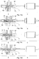
- FIGS. 5 a -5 d Show a longitudinal section through a conveying device of an alternative exemplary embodiment of a dosing apparatus according to the invention, for visualizing a filling procedure;
- FIG. 6 Shows a longitudinal section through a conveying device of a dosing apparatus according to the invention, having two independent conveying drives;
- FIG. 7 Shows a longitudinal section through a conveying device of an alternative exemplary embodiment of a dosing apparatus according to the invention, having two independent conveying drives;
- FIG. 8 Shows a longitudinal section through a conveying device of a dosing apparatus according to the invention, having three intake openings;
- FIGS. 8 a -8 i Show a series of part-enlargements through longitudinal sections of a conveying device according to FIG. 8 , for visualizing a pumping procedure;
- FIG. 9 Shows a longitudinal section through a conveying device of a dosing apparatus according to the invention, having an additional analysis opening;
- FIGS. 9 a -9 j Show a series of part-enlargements of longitudinal sections through a conveying device according to FIG. 9 , for visualizing an analysis and pumping procedure;
- FIGS. 10 a -10 e Show a series of longitudinal sections through a conveying device of a dosing apparatus according to the invention, having a common drive for both pistons;
- FIGS. 11 a -11 e Show a series of longitudinal sections through a conveying device of an alternative exemplary embodiment of a dosing apparatus according to the invention, having a common drive for both pistons;
- FIG. 12 a Shows a spatial illustration of a longitudinal section according to FIG. 11 c;
- FIG. 12 b Shows the bellows 34 marked by a circle in FIG. 12 a , but in a non-sectional form;
- FIGS. 13 a -13 d Show a series of longitudinal sections through a conveying device of an alternative exemplary embodiment of a dosing apparatus according to the invention, having two independent piston drives which are configured as cam gears;
- FIGS. 14 a -14 e Show a series of longitudinal sections through a conveying device of an alternative exemplary embodiment of a dosing apparatus according to the invention, for installation in a filling station for liquid pharmaceuticals.
- FIG. 1 shows a perspective illustration of a dosing apparatus 1 according to the invention.
- Said dosing apparatus additionally comprises a collapsible container 2 , the fluid to be dispensed being contained in the interior 3 thereof.
- the container 2 is connected to the conveying device 5 via a connection duct 24 in the closure piece 23 .
- the conveying device 5 comprises a cylinder 7 in which a first piston 9 and a second piston 10 are displaceably mounted.
- An intake opening 11 for suctioning the fluid from the container 2 is attached to the cylinder 7 .
- an outlet opening 12 which is fluidically connected with the dispensing opening 6 is moreover attached to the cylinder 7 .
- a pressure sensor 13 as well as a filling opening 14 which is closed off by a stopper 22 are attached to the cylinder 7 .
- the first piston 9 and the second piston 10 in the exemplary embodiment shown are driven by a common conveying drive 4 which here is configured as a spindle drive.
- FIG. 2 a shows a longitudinal section through the conveying device 5 in the initial state thereof.
- the two pistons 9 and 10 are mounted so as to be displaceable in the cylinder 7 .
- a plurality of annular seals 21 are attached to the pistons 9 and 10 .
- an intake opening 11 and an outlet opening 12 are present on the cylinder 7 of the conveying device 5 .
- FIG. 2 b shows the conveying device 5 after suctioning of fluid has been performed. It can be seen that the first piston 9 has been displaced in the direction of the outlet opening 12 , on account of which a volume 17 which is delimited internally and by the inner cylinder wall 8 has been formed between the end sides of the two pistons 9 and 10 .
- FIG. 2 c the two pistons 9 and 10 are displaced in the direction of the outlet opening 12 , so as to be mutually equidistant.
- the first piston 9 in the longitudinal direction of the cylinder 7 is now level with the outlet opening 12 .
- the second piston 10 proceeding from this position, may displaced further in the direction of the first piston 9 up to the point at which the two pistons 9 and 10 have end-side contact, as is shown in FIG. 2 f .
- the two pistons 9 and 10 proceeding from a position according to FIG. 2 d , may also be further displaced in an equidistant manner up to the point where the second piston 10 is level with the outlet opening 12 , corresponding to FIG. 2 e .
- an alternative ejection principle in which the first piston 9 is displaced in the direction of the second piston 10 , is implementable.
- FIG. 3 shows an alternative exemplary embodiment of a conveying device 5 of a dosing apparatus 1 according to the invention, in which additionally a pressure sensor 13 is attached to the cylinder 7 , so as to be level with the outlet opening 12 .
- FIGS. 4 a - d A sequence of longitudinal sections through the conveying device 5 of a further exemplary embodiment of a dosing apparatus 1 according to the invention is shown in FIGS. 4 a - d .
- An additional filling opening 14 is attached to the cylinder 7 in the case of said conveying device.
- FIG. 4 a shows the conveying device 5 in the initial position thereof, prior to filling the container 2 .
- the two pistons 9 and 10 having end-side contact, in the longitudinal direction of the cylinder 7 are positioned so as to be level with the intake opening 11 and the filling opening 14 .
- fluid communication between the filling opening 14 and the intake opening 11 is established by displacing the first piston 9 in the direction of the outlet opening 12 .
- the interior 3 of the container 2 may be filled with fluid on account of this fluid communication.
- the filling opening 14 is closed according to FIG. 4 c , using a stopper 22 .
- the conveying device 5 having a filled container 2 is again shown in the initial position of the former.
- FIGS. 5 a - d highlight the filling procedure of an alternative exemplary embodiment of a dosing apparatus 1 according to the invention.
- a longitudinal section through a corresponding conveying device 5 in which the filling opening 14 and the intake opening 11 are disposed on the cylinder 7 so as to be offset in the longitudinal direction is shown in FIG. 5 a .
- the first piston 9 is displaced in the direction of the outlet opening 12 ( FIG. 5 b ), so as to establish fluid communication between the filling opening 14 and the intake opening 11 .
- said fluid communication may again be interrupted after filling of the container 2 has been performed, by again displacing the piston 9 in the direction of the second piston 10 .
- the filling opening 14 is closed off using a stopper 22 as the last step of the filling procedure ( FIG. 5 d ).
- FIG. 6 shows a part-section through a dosing apparatus 1 according to the invention, in which the conveying device 5 is driven by two independent conveying drives 4 and 4 ′.
- the two conveying drives 4 and 4 ′ here are of identical construction and comprise in each case one motor 25 having a transmission 26 .
- the rotation movement generated by the motor 25 is transmitted to a spindle housing 28 which is rotatably mounted by way of the bearings 29 .
- the spindle housing 28 has a bore having a thread 30 into which the spindle 27 engages.
- a rotation movement which has been generated by the motor and the transmission 26 may be converted into a longitudinal movement of the piston 9 or 10 .
- a filling opening 14 is attached to the conveying device 5 , so as in the longitudinal direction to be level with the intake opening 11 , and is closed off by way of a stopper 22 .
- FIG. 7 shows an alternative exemplary embodiment of a dosing apparatus 1 according to the invention, having the conveying drive 4 and 4 ′ according to FIG. 6 .
- the filling opening 14 here is disposed on the cylinder 7 of the conveying device 5 , so as to be offset in the longitudinal direction in relation to the intake opening 11 .
- FIG. 8 shows a further exemplary embodiment of a dosing apparatus 1 according to the invention, having a conveying device 5 which has three independent intake openings 11 , 11 ′, and 11 ′′.
- FIGS. 8 a - i represent a series of longitudinal sections of said conveying device 5 , corresponding to a part-enlargement of FIG. 8 .
- the conveying device 5 is shown in the initial position thereof, wherein the first piston 9 and the second piston 10 are in end-side contact, so as to be level with the first intake opening 11 .
- FIG. 8 a the conveying device 5 is shown in the initial position thereof, wherein the first piston 9 and the second piston 10 are in end-side contact, so as to be level with the first intake opening 11 .
- the first piston 9 is displaced in the direction of the outlet opening 12 , on account of which a volume 17 for suctioning fluid is formed between the end sides of the first piston 9 and of the second piston 10 and the inner cylinder wall 8 .
- the two pistons 9 and 10 in the longitudinal cylinder direction are displaced in an equidistant manner, so as to be level with the second intake opening 11 ′.
- further fluid may be suctioned through the intake opening 11 ′ ( FIG. 8 d ).
- FIG. 8 d By again moving the first piston 9 in the direction of the outlet opening 12 , further fluid may be suctioned through the intake opening 11 ′ ( FIG. 8 d ).
- FIG. 8 e the two pistons 9 and 10 are again offset in an equidistant manner in the direction of the dispensing opening 12 , so as to be level with the third intake opening 11 ′′.
- fluid may be suctioned through the intake opening 11 ′′ by displacing the first piston 9 in the direction of the outlet opening 12 ( FIG. 8 f ).
- FIG. 8 g shows equidistant displacement of the first piston 9 and of the second piston 10 in relation to the dispensing opening 12 .
- FIG. 8 h illustrates the conveying device 5 in the ready state for dispensing, with the second piston 10 being level with the outlet opening 12 . After the fluid has been dispensed by displacing the first piston 9 in the direction of the second piston 10 , there is again end-side contact between the two pistons 9 and 10 , as is shown in FIG. 8 i.
- FIG. 9 shows a longitudinal section through a further exemplary embodiment of a dosing apparatus 1 according to the invention, having an additional analysis opening 15 on the cylinder 7 of the conveying device 5 .
- the corresponding conveying device 5 is shown in part-enlargement in FIG. 9 a .
- the two pistons 9 and 10 are located in the initial position, the end sides thereof in the longitudinal direction of the cylinder 7 being level with the intake opening 11 .
- the two pistons 9 and 10 are displaced so as to be level with the outlet opening 12 , as is highlighted in FIG. 9 b .
- fluid for example a patient's blood
- FIG. 9 fluid, for example a patient's blood
- FIGS. 10 a - e show an exemplary embodiment of a dosing apparatus 1 according to the invention, in which the two pistons 9 and 10 of the conveying device 5 are driven by a common conveying drive 4 .
- the first piston 9 here is indirectly coupled via a compression spring 33 to the conveying drive 4
- the second piston 10 is connected in a floating manner to the conveying drive 4 .
- actuation of the conveying drive proceeding from the initial position in FIG. 10 a , first leads to sole displacement of the first piston 9 in the direction of the outlet opening 12 .
- the second piston 10 is displaced in an equidistant manner to the first piston 9 in the direction of the dispensing opening 12 , as is shown in FIG. 10 c .
- the first piston 9 in the longitudinal direction of the cylinder 7 has now reached a position which is level with the dispensing opening 12 . It can be seen that the piston rod 16 of the first piston at this point also contacts the stop 32 . Further actuation of the conveying drive 4 leads to the spring 33 being compressed, as is shown in FIG. 10 e , on account of which the second piston 10 is further displaced in the direction of the dispensing opening 12 , again leading to dispensation of the fluid volume having been taken in.
- FIGS. 11 a - e show a further exemplary embodiment of a dosing apparatus 1 according to the invention, in which the conveying device 5 is driven by only one conveying drive 4 .
- the first piston 9 here is operatively connected in an indirect manner via the spring element 40 which is disposed therein with the conveying drive 4 .
- the second piston 10 by way of the piston rod 16 ′ may be pushed in the direction of the outlet opening 12 , and by way of the first piston 9 in the direction of the intake opening 11 .
- the first piston 9 and the second piston 10 are configured so as to be integral and are interconnected by way of a bellows 34 .
- the pistons 9 and 10 and the bellows 34 may be implemented from a single part, for example from silicone, TPE, or bromobutyl rubber, for example.
- FIG. 12 a shows a spatial illustration of a longitudinal section according to FIG. 11 c . It can be seen that the first piston 9 and the second piston 10 are displaced in an equidistant manner in the direction of the outlet opening 12 . Here, the first piston 9 is moved by way of the spring element 40 , and the second piston 10 is pushed by the piston rod 16 ′.
- FIG. 12 b shows the bellows 34 which is marked by a circle in FIG. 12 a , but not as part-section but in a spatial illustration.
- FIGS. 13 a - d show a further dosing apparatus 1 according to the invention, in which the pistons 9 and 10 of the conveying device 5 are driven by two independent conveying drives 4 and 4 ′.
- these are two cam gears 18 and 18 ′.
- Said cam gears 18 and 18 ′ comprise in each case one control disc 19 having a guide groove 31 by way of which a plunger 20 is articulated thereon.
- FIGS. 14 a - e show the conveying device 5 of a further alternative exemplary embodiment of a dosing apparatus 1 according to the invention, for installation in a filling station for liquid pharmaceutical formulae.
- the conveying device 5 in this case has a cylinder 7 which is integrally embodied as a U-shaped housing 36 . While the first piston 9 transitions into a typical straight piston rod 16 ′′, the second piston 10 is connected to a U-shaped piston rod 35 which has a bend of 180°.
- the conveying device 5 is not only without a valve, but is also conceived so as to have no seals or piston rings on the pistons.
- the housing 36 has a space 37 for the bend in the piston rod 35 , and ducts 38 and 39 for flushing the conveying device 5 .
Abstract
Description
Claims (11)
Priority Applications (1)
| Application Number | Priority Date | Filing Date | Title |
|---|---|---|---|
| US15/931,100 US11040146B2 (en) | 2015-01-27 | 2020-05-13 | Dosing apparatus for dispensing a fluid under aseptic conditions |
Applications Claiming Priority (5)
| Application Number | Priority Date | Filing Date | Title |
|---|---|---|---|
| EP15152703.3A EP3050585B1 (en) | 2015-01-27 | 2015-01-27 | Dosing device for dispensing a fluid under aseptic conditions |
| EP15152703 | 2015-01-27 | ||
| EP15152703.3 | 2015-01-27 | ||
| US15/006,285 US10653846B2 (en) | 2015-01-27 | 2016-01-26 | Dosing apparatus for dispensing a fluid under aseptic conditions |
| US15/931,100 US11040146B2 (en) | 2015-01-27 | 2020-05-13 | Dosing apparatus for dispensing a fluid under aseptic conditions |
Related Parent Applications (1)
| Application Number | Title | Priority Date | Filing Date |
|---|---|---|---|
| US15/006,285 Division US10653846B2 (en) | 2015-01-27 | 2016-01-26 | Dosing apparatus for dispensing a fluid under aseptic conditions |
Publications (2)
| Publication Number | Publication Date |
|---|---|
| US20200297935A1 US20200297935A1 (en) | 2020-09-24 |
| US11040146B2 true US11040146B2 (en) | 2021-06-22 |
Family
ID=52446210
Family Applications (2)
| Application Number | Title | Priority Date | Filing Date |
|---|---|---|---|
| US15/006,285 Active 2037-06-01 US10653846B2 (en) | 2015-01-27 | 2016-01-26 | Dosing apparatus for dispensing a fluid under aseptic conditions |
| US15/931,100 Active US11040146B2 (en) | 2015-01-27 | 2020-05-13 | Dosing apparatus for dispensing a fluid under aseptic conditions |
Family Applications Before (1)
| Application Number | Title | Priority Date | Filing Date |
|---|---|---|---|
| US15/006,285 Active 2037-06-01 US10653846B2 (en) | 2015-01-27 | 2016-01-26 | Dosing apparatus for dispensing a fluid under aseptic conditions |
Country Status (4)
| Country | Link |
|---|---|
| US (2) | US10653846B2 (en) |
| EP (1) | EP3050585B1 (en) |
| CN (1) | CN105816943B (en) |
| DK (1) | DK3050585T3 (en) |
Families Citing this family (34)
| Publication number | Priority date | Publication date | Assignee | Title |
|---|---|---|---|---|
| DK1762259T3 (en) | 2005-09-12 | 2011-01-03 | Unomedical As | Infusion set insertion device with a first and a second spring assembly |
| CA2792138A1 (en) | 2010-03-30 | 2011-10-06 | Unomedical A/S | Medical device |
| US10194938B2 (en) | 2011-03-14 | 2019-02-05 | UnoMedical, AS | Inserter system with transport protection |
| EP2583715A1 (en) | 2011-10-19 | 2013-04-24 | Unomedical A/S | Infusion tube system and method for manufacture |
| CA2942102C (en) * | 2014-04-07 | 2021-08-10 | Becton, Dickinson And Company | Rotational metering pump for insulin patch |
| US10967121B2 (en) | 2014-04-07 | 2021-04-06 | Becton, Dickinson And Company | Rotational metering pump for insulin patch |
| US10675404B2 (en) | 2014-04-07 | 2020-06-09 | Becton, Dickinson And Company | Rotational metering pump for insulin patch |
| JP6714007B2 (en) * | 2015-02-02 | 2020-06-24 | サノフィ−アベンティス・ドイチュラント・ゲゼルシャフト・ミット・ベシュレンクテル・ハフツング | How to prime a medical pump |
| US11357912B2 (en) | 2016-01-19 | 2022-06-14 | Unomedical A/S | Cannula and infusion devices |
| TWI746569B (en) | 2016-06-08 | 2021-11-21 | 瑞士商瑞健醫療股份有限公司 | Dosiergerat, injektionsvorrichtung und verwendung |
| CN109310818B (en) | 2016-06-08 | 2021-10-26 | 艾斯曲尔医疗公司 | Device for dispensing a fluid |
| US10561797B2 (en) | 2016-08-14 | 2020-02-18 | Insulet Corporation | Drug delivery device with indicator |
| CN106420349B (en) * | 2016-10-31 | 2019-09-17 | 成都杰仕德科技有限公司 | A kind of cillin bottle automated dispensing system and method |
| CN109890437B (en) * | 2016-11-01 | 2021-11-19 | 赛诺菲-安万特德国有限公司 | Auxiliary device for an injection device |
| JP7053614B2 (en) | 2016-11-28 | 2022-04-12 | エスエイチエル・メディカル・アーゲー | Device to administer a substance |
| US10603440B2 (en) | 2017-01-19 | 2020-03-31 | Insulet Corporation | Cartridge hold-up volume reduction |
| EP3354303B1 (en) * | 2017-01-31 | 2020-01-08 | Société Industrielle de Sonceboz S.A. | Drug delivery system |
| WO2019028342A1 (en) | 2017-08-03 | 2019-02-07 | Insulet Corporation | Micro piston pump |
| US11786668B2 (en) | 2017-09-25 | 2023-10-17 | Insulet Corporation | Drug delivery devices, systems, and methods with force transfer elements |
| US10869961B2 (en) | 2017-11-06 | 2020-12-22 | Sorrel Medical Ltd. | Local disinfection for drug delivery system |
| JP2021517004A (en) * | 2018-02-16 | 2021-07-15 | デバイオテック・ソシエテ・アノニム | Drug delivery system status indicator |
| US10874803B2 (en) | 2018-05-31 | 2020-12-29 | Insulet Corporation | Drug cartridge with drive system |
| DE102018113421A1 (en) * | 2018-06-06 | 2019-12-12 | Prominent Gmbh | Dosing pump with linear motor |
| US11174852B2 (en) | 2018-07-20 | 2021-11-16 | Becton, Dickinson And Company | Reciprocating pump |
| EP3856119A4 (en) * | 2018-09-24 | 2022-05-25 | Oh Pharmaceutical Co., Ltd. | Infusion system |
| EP3744368A1 (en) | 2018-10-05 | 2020-12-02 | Sorrel Medical Ltd. | Triggering sequence |
| US11446435B2 (en) | 2018-11-28 | 2022-09-20 | Insulet Corporation | Drug delivery shuttle pump system and valve assembly |
| EP3956903A4 (en) * | 2019-04-17 | 2023-01-11 | ICU Medical, Inc. | System for onboard electronic encoding of the contents and administration parameters of iv containers and the secure use and disposal thereof |
| EP3972672A4 (en) | 2019-05-20 | 2023-06-21 | Unomedical A/S | Rotatable infusion device and methods thereof |
| US20220218893A1 (en) * | 2021-01-11 | 2022-07-14 | Insulet Corporation | Linear activated drug dosing pump system |
| CN115025322A (en) * | 2021-03-03 | 2022-09-09 | 南微医学科技股份有限公司 | Liquid conveying system and stable liquid discharging method |
| IT202100027071A1 (en) * | 2021-10-21 | 2023-04-21 | Bormioli Pharma Spa | DISPENSER OF A FLUID SUBSTANCE |
| WO2024008451A1 (en) | 2022-07-05 | 2024-01-11 | Shl Medical Ag | A sub-assembly of a pump device |
| WO2024052239A1 (en) * | 2022-09-06 | 2024-03-14 | Shl Medical Ag | Dosing apparatus for parenteral delivery of fluids |
Citations (20)
| Publication number | Priority date | Publication date | Assignee | Title |
|---|---|---|---|---|
| US1516032A (en) | 1923-08-02 | 1924-11-18 | Charles E White | Pump |
| GB1508665A (en) | 1974-06-27 | 1978-04-26 | Brundbjerg N | Piston pump |
| EP0701061A1 (en) | 1994-09-09 | 1996-03-13 | Brother Kogyo Kabushiki Kaisha | Pump and pump unit and method |
| US5513779A (en) | 1993-12-03 | 1996-05-07 | Hormec Technic Sa | Modular metering device |
| US20010025189A1 (en) * | 1998-09-08 | 2001-09-27 | Ulrich Haueter | Module for a computer interface |
| US20020169439A1 (en) * | 2001-02-22 | 2002-11-14 | Flaherty J. Christopher | Modular infusion device and method |
| US20030233069A1 (en) | 2002-06-14 | 2003-12-18 | John Gillespie | Infusion pump |
| US20050177111A1 (en) | 2004-02-06 | 2005-08-11 | Shaul Ozeri | Miniature infusion pump |
| US20060270961A1 (en) * | 2005-05-19 | 2006-11-30 | Vasogen Ireland Limited | Sample management unit |
| US20100121306A1 (en) * | 2007-07-20 | 2010-05-13 | Ofer Yodfat | Collapsible reservoir for use with a delivery device |
| US20110073620A1 (en) | 2007-11-17 | 2011-03-31 | Brian Leonard Verrilli | Twisting translational displacement pump cartridge |
| US20110178461A1 (en) | 2009-09-02 | 2011-07-21 | Medtronic Minimed, Inc. | Insertion device systems and methods |
| US20110196337A1 (en) | 2007-08-07 | 2011-08-11 | Sensile Pat Ag | Modular Drug Delivery Device for Administering Discrete Doses of a Medicament |
| EP2628494A1 (en) | 2012-02-17 | 2013-08-21 | Sensile Pat AG | Liquid storage and delivery system |
| WO2014090745A1 (en) | 2012-12-10 | 2014-06-19 | Sanofi-Aventis Deutschland Gmbh | Medical pump and method of operating the same |
| US20140276537A1 (en) | 2013-03-15 | 2014-09-18 | Tandem Diabetes Care, Inc. | Infusion device occlusion detection system |
| WO2014207532A1 (en) | 2013-06-25 | 2014-12-31 | Swissinnov Product Sarl | Positive-displacement micropump |
| US20150119804A1 (en) | 2013-10-25 | 2015-04-30 | Medtronic, Inc. | Personalized housing for ambulatory infusion device |
| US20180126097A1 (en) | 2006-02-09 | 2018-05-10 | Deka Products Limited Partnership | Adhesive and Peripheral Systems and Methods for Medical Devices |
| US20180126098A1 (en) | 2010-08-26 | 2018-05-10 | Alexza Pharmaceuticals, Inc. | Heat Units Using a Solid Fuel Capable of Undergoing an Exothermic Metal Oxidation-Reduction Reaction Propagated without an Igniter |
-
2015
- 2015-01-27 EP EP15152703.3A patent/EP3050585B1/en active Active
- 2015-01-27 DK DK15152703.3T patent/DK3050585T3/en active
-
2016
- 2016-01-26 CN CN201610052079.1A patent/CN105816943B/en active Active
- 2016-01-26 US US15/006,285 patent/US10653846B2/en active Active
-
2020
- 2020-05-13 US US15/931,100 patent/US11040146B2/en active Active
Patent Citations (21)
| Publication number | Priority date | Publication date | Assignee | Title |
|---|---|---|---|---|
| US1516032A (en) | 1923-08-02 | 1924-11-18 | Charles E White | Pump |
| GB1508665A (en) | 1974-06-27 | 1978-04-26 | Brundbjerg N | Piston pump |
| US5513779A (en) | 1993-12-03 | 1996-05-07 | Hormec Technic Sa | Modular metering device |
| EP0701061A1 (en) | 1994-09-09 | 1996-03-13 | Brother Kogyo Kabushiki Kaisha | Pump and pump unit and method |
| US20010025189A1 (en) * | 1998-09-08 | 2001-09-27 | Ulrich Haueter | Module for a computer interface |
| US20020169439A1 (en) * | 2001-02-22 | 2002-11-14 | Flaherty J. Christopher | Modular infusion device and method |
| US20030233069A1 (en) | 2002-06-14 | 2003-12-18 | John Gillespie | Infusion pump |
| US20050177111A1 (en) | 2004-02-06 | 2005-08-11 | Shaul Ozeri | Miniature infusion pump |
| US20060270961A1 (en) * | 2005-05-19 | 2006-11-30 | Vasogen Ireland Limited | Sample management unit |
| US20180126097A1 (en) | 2006-02-09 | 2018-05-10 | Deka Products Limited Partnership | Adhesive and Peripheral Systems and Methods for Medical Devices |
| US20100121306A1 (en) * | 2007-07-20 | 2010-05-13 | Ofer Yodfat | Collapsible reservoir for use with a delivery device |
| US20110196337A1 (en) | 2007-08-07 | 2011-08-11 | Sensile Pat Ag | Modular Drug Delivery Device for Administering Discrete Doses of a Medicament |
| US20110073620A1 (en) | 2007-11-17 | 2011-03-31 | Brian Leonard Verrilli | Twisting translational displacement pump cartridge |
| US20110178461A1 (en) | 2009-09-02 | 2011-07-21 | Medtronic Minimed, Inc. | Insertion device systems and methods |
| US20180126098A1 (en) | 2010-08-26 | 2018-05-10 | Alexza Pharmaceuticals, Inc. | Heat Units Using a Solid Fuel Capable of Undergoing an Exothermic Metal Oxidation-Reduction Reaction Propagated without an Igniter |
| EP2628494A1 (en) | 2012-02-17 | 2013-08-21 | Sensile Pat AG | Liquid storage and delivery system |
| WO2014090745A1 (en) | 2012-12-10 | 2014-06-19 | Sanofi-Aventis Deutschland Gmbh | Medical pump and method of operating the same |
| US20150290389A1 (en) * | 2012-12-10 | 2015-10-15 | Sanofi-Aventis Deutschland Gmbh | Medical pump and method of operating the same |
| US20140276537A1 (en) | 2013-03-15 | 2014-09-18 | Tandem Diabetes Care, Inc. | Infusion device occlusion detection system |
| WO2014207532A1 (en) | 2013-06-25 | 2014-12-31 | Swissinnov Product Sarl | Positive-displacement micropump |
| US20150119804A1 (en) | 2013-10-25 | 2015-04-30 | Medtronic, Inc. | Personalized housing for ambulatory infusion device |
Non-Patent Citations (2)
| Title |
|---|
| European Search Report Corresponding to 15152703 dated Aug. 19, 2015. |
| OOE Work Product Corresponding to EP 15 152 703.3 mailed Nov. 6, 2017. |
Also Published As
| Publication number | Publication date |
|---|---|
| EP3050585B1 (en) | 2019-04-10 |
| DK3050585T3 (en) | 2019-07-08 |
| US10653846B2 (en) | 2020-05-19 |
| EP3050585A1 (en) | 2016-08-03 |
| CN105816943B (en) | 2020-12-01 |
| US20160213851A1 (en) | 2016-07-28 |
| CN105816943A (en) | 2016-08-03 |
| US20200297935A1 (en) | 2020-09-24 |
Similar Documents
| Publication | Publication Date | Title |
|---|---|---|
| US11040146B2 (en) | Dosing apparatus for dispensing a fluid under aseptic conditions | |
| EP2258333B1 (en) | Device for filling a flexible reservoir | |
| DK2510960T3 (en) | Infusion pump device with cylinder piston metering unit and optical piston position detection | |
| JP2014513613A (en) | Dosing mechanism | |
| RU2692445C2 (en) | Dosing fluid medium in amount of less than one milliliter | |
| EP2510962A1 (en) | Infusion pump device with re-filling scheme for cylinder-piston dosing unit | |
| CN109310818B (en) | Device for dispensing a fluid | |
| EP2510961A1 (en) | Infusion pump device with improved priming of the fluidic system and method for priming such an infusion pump device | |
| US20130261599A1 (en) | Dosing Unit With Safety Valve | |
| US11185629B2 (en) | Dosing apparatus and injection device | |
| US8197451B2 (en) | Ampoule with a seal in two compression states | |
| US9095650B2 (en) | Precision fluid delivery systems | |
| US11395876B2 (en) | Sterile pump module for an infusion pump | |
| CN108601889B (en) | Intermittent infusion device | |
| CN112888414B (en) | Medical pump system | |
| WO2008055689A1 (en) | Container for receiving medical liquids |
Legal Events
| Date | Code | Title | Description |
|---|---|---|---|
| FEPP | Fee payment procedure |
Free format text: ENTITY STATUS SET TO UNDISCOUNTED (ORIGINAL EVENT CODE: BIG.); ENTITY STATUS OF PATENT OWNER: LARGE ENTITY |
|
| FEPP | Fee payment procedure |
Free format text: ENTITY STATUS SET TO SMALL (ORIGINAL EVENT CODE: SMAL); ENTITY STATUS OF PATENT OWNER: LARGE ENTITY |
|
| AS | Assignment |
Owner name: IDORSIA PHARMACEUTICALS LTD, SWITZERLAND Free format text: ASSIGNMENT OF ASSIGNORS INTEREST;ASSIGNORS:WEIBEL, LUDWIG DANIEL;WYLER, SAMUEL;REEL/FRAME:052732/0817 Effective date: 20160115 |
|
| AS | Assignment |
Owner name: SHL MEDICAL AG, SWITZERLAND Free format text: ASSIGNMENT OF ASSIGNORS INTEREST;ASSIGNOR:IDORSIA PHARMACEUTICALS LTD.;REEL/FRAME:053923/0566 Effective date: 20200916 |
|
| FEPP | Fee payment procedure |
Free format text: ENTITY STATUS SET TO UNDISCOUNTED (ORIGINAL EVENT CODE: BIG.); ENTITY STATUS OF PATENT OWNER: LARGE ENTITY |
|
| STPP | Information on status: patent application and granting procedure in general |
Free format text: RESPONSE TO NON-FINAL OFFICE ACTION ENTERED AND FORWARDED TO EXAMINER |
|
| STPP | Information on status: patent application and granting procedure in general |
Free format text: NON FINAL ACTION MAILED |
|
| STPP | Information on status: patent application and granting procedure in general |
Free format text: RESPONSE TO NON-FINAL OFFICE ACTION ENTERED AND FORWARDED TO EXAMINER |
|
| FEPP | Fee payment procedure |
Free format text: PETITION RELATED TO MAINTENANCE FEES GRANTED (ORIGINAL EVENT CODE: PTGR); ENTITY STATUS OF PATENT OWNER: LARGE ENTITY |
|
| STPP | Information on status: patent application and granting procedure in general |
Free format text: NOTICE OF ALLOWANCE MAILED -- APPLICATION RECEIVED IN OFFICE OF PUBLICATIONS |
|
| STPP | Information on status: patent application and granting procedure in general |
Free format text: PUBLICATIONS -- ISSUE FEE PAYMENT RECEIVED |
|
| STPP | Information on status: patent application and granting procedure in general |
Free format text: PUBLICATIONS -- ISSUE FEE PAYMENT VERIFIED |
|
| STCF | Information on status: patent grant |
Free format text: PATENTED CASE |