EP4550208A1 - Ic sheet, and passport and contactless ic card with ic sheet - Google Patents
Ic sheet, and passport and contactless ic card with ic sheet Download PDFInfo
- Publication number
- EP4550208A1 EP4550208A1 EP23831364.7A EP23831364A EP4550208A1 EP 4550208 A1 EP4550208 A1 EP 4550208A1 EP 23831364 A EP23831364 A EP 23831364A EP 4550208 A1 EP4550208 A1 EP 4550208A1
- Authority
- EP
- European Patent Office
- Prior art keywords
- sheet
- sheets
- thickness dimension
- chip
- cover
- Prior art date
- Legal status (The legal status is an assumption and is not a legal conclusion. Google has not performed a legal analysis and makes no representation as to the accuracy of the status listed.)
- Pending
Links
Images


Classifications
-
- G—PHYSICS
- G06—COMPUTING OR CALCULATING; COUNTING
- G06K—GRAPHICAL DATA READING; PRESENTATION OF DATA; RECORD CARRIERS; HANDLING RECORD CARRIERS
- G06K19/00—Record carriers for use with machines and with at least a part designed to carry digital markings
- G06K19/06—Record carriers for use with machines and with at least a part designed to carry digital markings characterised by the kind of the digital marking, e.g. shape, nature, code
- G06K19/067—Record carriers with conductive marks, printed circuits or semiconductor circuit elements, e.g. credit or identity cards also with resonating or responding marks without active components
- G06K19/07—Record carriers with conductive marks, printed circuits or semiconductor circuit elements, e.g. credit or identity cards also with resonating or responding marks without active components with integrated circuit chips
- G06K19/077—Constructional details, e.g. mounting of circuits in the carrier
- G06K19/07749—Constructional details, e.g. mounting of circuits in the carrier the record carrier being capable of non-contact communication, e.g. constructional details of the antenna of a non-contact smart card
-
- B—PERFORMING OPERATIONS; TRANSPORTING
- B42—BOOKBINDING; ALBUMS; FILES; SPECIAL PRINTED MATTER
- B42D—BOOKS; BOOK COVERS; LOOSE LEAVES; PRINTED MATTER CHARACTERISED BY IDENTIFICATION OR SECURITY FEATURES; PRINTED MATTER OF SPECIAL FORMAT OR STYLE NOT OTHERWISE PROVIDED FOR; DEVICES FOR USE THEREWITH AND NOT OTHERWISE PROVIDED FOR; MOVABLE-STRIP WRITING OR READING APPARATUS
- B42D25/00—Information-bearing cards or sheet-like structures characterised by identification or security features; Manufacture thereof
- B42D25/20—Information-bearing cards or sheet-like structures characterised by identification or security features; Manufacture thereof characterised by a particular use or purpose
- B42D25/24—Passports
-
- B—PERFORMING OPERATIONS; TRANSPORTING
- B42—BOOKBINDING; ALBUMS; FILES; SPECIAL PRINTED MATTER
- B42D—BOOKS; BOOK COVERS; LOOSE LEAVES; PRINTED MATTER CHARACTERISED BY IDENTIFICATION OR SECURITY FEATURES; PRINTED MATTER OF SPECIAL FORMAT OR STYLE NOT OTHERWISE PROVIDED FOR; DEVICES FOR USE THEREWITH AND NOT OTHERWISE PROVIDED FOR; MOVABLE-STRIP WRITING OR READING APPARATUS
- B42D13/00—Loose leaves modified for binding; Inserts
-
- B—PERFORMING OPERATIONS; TRANSPORTING
- B42—BOOKBINDING; ALBUMS; FILES; SPECIAL PRINTED MATTER
- B42D—BOOKS; BOOK COVERS; LOOSE LEAVES; PRINTED MATTER CHARACTERISED BY IDENTIFICATION OR SECURITY FEATURES; PRINTED MATTER OF SPECIAL FORMAT OR STYLE NOT OTHERWISE PROVIDED FOR; DEVICES FOR USE THEREWITH AND NOT OTHERWISE PROVIDED FOR; MOVABLE-STRIP WRITING OR READING APPARATUS
- B42D25/00—Information-bearing cards or sheet-like structures characterised by identification or security features; Manufacture thereof
- B42D25/20—Information-bearing cards or sheet-like structures characterised by identification or security features; Manufacture thereof characterised by a particular use or purpose
- B42D25/23—Identity cards
-
- B—PERFORMING OPERATIONS; TRANSPORTING
- B42—BOOKBINDING; ALBUMS; FILES; SPECIAL PRINTED MATTER
- B42D—BOOKS; BOOK COVERS; LOOSE LEAVES; PRINTED MATTER CHARACTERISED BY IDENTIFICATION OR SECURITY FEATURES; PRINTED MATTER OF SPECIAL FORMAT OR STYLE NOT OTHERWISE PROVIDED FOR; DEVICES FOR USE THEREWITH AND NOT OTHERWISE PROVIDED FOR; MOVABLE-STRIP WRITING OR READING APPARATUS
- B42D25/00—Information-bearing cards or sheet-like structures characterised by identification or security features; Manufacture thereof
- B42D25/30—Identification or security features, e.g. for preventing forgery
- B42D25/305—Associated digital information
-
- G—PHYSICS
- G06—COMPUTING OR CALCULATING; COUNTING
- G06K—GRAPHICAL DATA READING; PRESENTATION OF DATA; RECORD CARRIERS; HANDLING RECORD CARRIERS
- G06K19/00—Record carriers for use with machines and with at least a part designed to carry digital markings
- G06K19/02—Record carriers for use with machines and with at least a part designed to carry digital markings characterised by the selection of materials, e.g. to avoid wear during transport through the machine
-
- G—PHYSICS
- G06—COMPUTING OR CALCULATING; COUNTING
- G06K—GRAPHICAL DATA READING; PRESENTATION OF DATA; RECORD CARRIERS; HANDLING RECORD CARRIERS
- G06K19/00—Record carriers for use with machines and with at least a part designed to carry digital markings
- G06K19/02—Record carriers for use with machines and with at least a part designed to carry digital markings characterised by the selection of materials, e.g. to avoid wear during transport through the machine
- G06K19/027—Record carriers for use with machines and with at least a part designed to carry digital markings characterised by the selection of materials, e.g. to avoid wear during transport through the machine the material being suitable for use as a textile, e.g. woven-based RFID-like labels designed for attachment to laundry items
-
- G—PHYSICS
- G06—COMPUTING OR CALCULATING; COUNTING
- G06K—GRAPHICAL DATA READING; PRESENTATION OF DATA; RECORD CARRIERS; HANDLING RECORD CARRIERS
- G06K19/00—Record carriers for use with machines and with at least a part designed to carry digital markings
- G06K19/06—Record carriers for use with machines and with at least a part designed to carry digital markings characterised by the kind of the digital marking, e.g. shape, nature, code
- G06K19/067—Record carriers with conductive marks, printed circuits or semiconductor circuit elements, e.g. credit or identity cards also with resonating or responding marks without active components
- G06K19/07—Record carriers with conductive marks, printed circuits or semiconductor circuit elements, e.g. credit or identity cards also with resonating or responding marks without active components with integrated circuit chips
- G06K19/077—Constructional details, e.g. mounting of circuits in the carrier
- G06K19/0772—Physical layout of the record carrier
- G06K19/07728—Physical layout of the record carrier the record carrier comprising means for protection against impact or bending, e.g. protective shells or stress-absorbing layers around the integrated circuit
-
- G—PHYSICS
- G06—COMPUTING OR CALCULATING; COUNTING
- G06K—GRAPHICAL DATA READING; PRESENTATION OF DATA; RECORD CARRIERS; HANDLING RECORD CARRIERS
- G06K19/00—Record carriers for use with machines and with at least a part designed to carry digital markings
- G06K19/06—Record carriers for use with machines and with at least a part designed to carry digital markings characterised by the kind of the digital marking, e.g. shape, nature, code
- G06K19/067—Record carriers with conductive marks, printed circuits or semiconductor circuit elements, e.g. credit or identity cards also with resonating or responding marks without active components
- G06K19/07—Record carriers with conductive marks, printed circuits or semiconductor circuit elements, e.g. credit or identity cards also with resonating or responding marks without active components with integrated circuit chips
- G06K19/077—Constructional details, e.g. mounting of circuits in the carrier
- G06K19/07749—Constructional details, e.g. mounting of circuits in the carrier the record carrier being capable of non-contact communication, e.g. constructional details of the antenna of a non-contact smart card
- G06K19/0775—Constructional details, e.g. mounting of circuits in the carrier the record carrier being capable of non-contact communication, e.g. constructional details of the antenna of a non-contact smart card arrangements for connecting the integrated circuit to the antenna
-
- B—PERFORMING OPERATIONS; TRANSPORTING
- B42—BOOKBINDING; ALBUMS; FILES; SPECIAL PRINTED MATTER
- B42D—BOOKS; BOOK COVERS; LOOSE LEAVES; PRINTED MATTER CHARACTERISED BY IDENTIFICATION OR SECURITY FEATURES; PRINTED MATTER OF SPECIAL FORMAT OR STYLE NOT OTHERWISE PROVIDED FOR; DEVICES FOR USE THEREWITH AND NOT OTHERWISE PROVIDED FOR; MOVABLE-STRIP WRITING OR READING APPARATUS
- B42D25/00—Information-bearing cards or sheet-like structures characterised by identification or security features; Manufacture thereof
- B42D25/40—Manufacture
- B42D25/45—Associating two or more layers
- B42D25/455—Associating two or more layers using heat
-
- B—PERFORMING OPERATIONS; TRANSPORTING
- B42—BOOKBINDING; ALBUMS; FILES; SPECIAL PRINTED MATTER
- B42D—BOOKS; BOOK COVERS; LOOSE LEAVES; PRINTED MATTER CHARACTERISED BY IDENTIFICATION OR SECURITY FEATURES; PRINTED MATTER OF SPECIAL FORMAT OR STYLE NOT OTHERWISE PROVIDED FOR; DEVICES FOR USE THEREWITH AND NOT OTHERWISE PROVIDED FOR; MOVABLE-STRIP WRITING OR READING APPARATUS
- B42D25/00—Information-bearing cards or sheet-like structures characterised by identification or security features; Manufacture thereof
- B42D25/40—Manufacture
- B42D25/45—Associating two or more layers
- B42D25/46—Associating two or more layers using pressure
Definitions
- the present invention relates to an IC sheet incorporating a non-contact readable and writable IC chip, and a passport and a non-contact IC card including the IC sheet.
- An IC sheet in which an IC chip is built in a sheet body is often used for, for example, a transportation IC card.
- the thickness of such an IC sheet having a card size is formed to be about 0.76 mm conforming to the standard of the non-contact IC card defined in JIS.
- an IC sheet incorporating an IC chip is also used in, for example, a passport, and in particular, in a booklet-shaped passport, the IC sheet is required to be thinner than an IC sheet used for a transportation IC card in order to prevent bulkiness due to the IC sheet.
- Patent Literature 1 by the present applicant can be cited.
- the IC sheet described in Patent Literature 1 includes an inlet in which an IC chip and an antenna (antenna coil) are held on a support sheet (base sheet), two cover sheets disposed on the front side (upper side) of the inlet, and one cover sheet disposed on the back side (lower side).
- the inlet and the cover sheets are integrated by hot pressing in a state where they are stacked.
- Patent Literature 1 JP 2015-184774 A
- amorphous polyethylene terephthalate (PET-G) is used as material of the cover sheet.
- PET-G amorphous polyethylene terephthalate
- the reason why amorphous polyethylene terephthalate (PET-G) is used as the material of the cover sheet as described above is that amorphous polyethylene terephthalate (PET-G) has the strength required for an IC card and that the workability of hot pressing in manufacturing is taken into consideration.
- PET-G if the thickness dimension of the cover sheet including amorphous polyethylene terephthalate (PET-G) is reduced, there is a disadvantage that the strength is insufficient.
- PC polycarbonate
- the material of the cover sheet is polycarbonate
- sufficient strength can be obtained even in a case where the thickness of the cover sheet is relatively thin.
- polycarbonate is more excellent in mechanical strength (flexural strength and impact resistance) than amorphous polyethylene terephthalate.
- polycarbonate is inferior in adhesiveness (heat weldability) to polyethylene terephthalate, when the inlet and the cover sheet are integrated by hot pressing, peeling easily occurs between the two (the inlet and the cover sheet).
- This problem can be solved by using an adhesive when the inlet and the cover sheet are integrated, but in that case, a process of applying the adhesive is required in manufacturing, and productivity is lowered.
- a process of applying the adhesive is required in manufacturing, and productivity is lowered.
- the thickness dimension increases by the amount of the formed adhesive layer, there is a limit to thinning of the IC card.
- the present invention has been made to solve the above problems, and it is an object of the present invention to reliably prevent cover sheets from peeling off from an inlet without lowering productivity even in a case where polycarbonate is selected as material of the cover sheets in an IC sheet including the inlet and the cover sheets disposed on and under the inlet.
- An object of the present invention is to prevent a passport mounted with an IC sheet from being bulky due to the IC sheet.
- An object of the present invention is to obtain a non-contact IC card having excellent security and high decorativeness and designability.
- the present invention is directed to an IC sheet including: an inlet 2 including an IC chip 7, an antenna 8 that is connected to the IC chip 7, and a support sheet 10 that includes a nonwoven fabric and holds the IC chip 7 and the antenna 8; and cover sheets 3 and 4 that include polycarbonate and are disposed under and on the inlet 2, respectively. Then, polycarbonate resin constituting the cover sheets 3 and 4 is solidified in a state of entering between fibers of the nonwoven fabric of the support sheet 10, so that the cover sheets 3 and 4 and the support sheet 10 are integrated.
- a total thickness dimension of the thickness dimension T1 and the thickness dimension T2 is preferably set to 0.35 mm or more and 0.5 mm or less.
- the minimum dimension of each of the thickness dimension T1 of the lower cover sheet 3 and the thickness dimension T2 of the upper cover sheet 4 is preferably set to 0.05 mm or more.
- An over sheet 28 including a sheet body including resin as material is disposed on an outer surface of the lower cover sheet 3 and/or an outer surface of the upper cover sheet 4.
- a relief portion 24 including a recess is formed in the lower cover sheet 3, and the IC chip 7 is accommodated in the relief portion 24 in a state where the support sheet 10 and both the cover sheets 3 and 4 are stacked.
- the lower cover sheet 3 includes a lower base sheet 18 that has a flat plate shape and in which a lower through hole 20 is formed, and a lower seal sheet 19 that has a flat plate shape and has a thickness smaller than a thickness of the lower base sheet 18.
- the lower base sheet 18 is disposed on the support sheet 10
- the lower seal sheet 19 is disposed on the lower base sheet 18, and the lower through hole 20 and the lower seal sheet 19 that closes the lower through hole 20 form the relief portion 24.
- the lower cover sheet 3 includes a lower base sheet 18 that has a flat plate shape and in which a lower through hole 20 is formed, and a lower seal sheet 19 that has a flat plate shape and has a thickness smaller than a thickness of the lower base sheet 18.
- the lower base sheet 18 is disposed on the support sheet 10, and the lower seal sheet 19 is disposed on the lower base sheet 18.
- the upper cover sheet 4 includes an upper base sheet 27 that has a flat plate shape and in which an upper through hole 40 is formed, and an upper seal sheet 39 that has a flat plate shape and has a thickness smaller than a thickness of the upper base sheet 27.
- the upper base sheet 27 is disposed on the support sheet 10, and the upper seal sheet 39 is disposed on the upper base sheet 27.
- a passport of the present invention includes the IC sheet 1 described in any one of the above.
- a non-contact IC card of the present invention includes the IC sheet 1 described in any one of the above.
- An exterior sheet 42 is stacked on at least one of an upper surface or a lower surface of the IC sheet 1.
- both the cover sheets 4 and 3 can be firmly integrated.
- the polycarbonate resin is solidified in a state of entering between the fibers of the nonwoven fabric which is the support sheet 10, so that the fibers of the nonwoven fabric and the polycarbonate resin can be firmly joined to firmly integrate the three parts (the upper and lower cover sheets 4 and 3 and the inlet 2) in a state where the inlet 2 is sandwiched between the upper and lower cover sheets 4 and 3.
- the cover sheets 4 and 3 can be reliably prevented from peeling off from the inlet 2.
- the IC sheet of the present invention can be manufactured by disposing the upper and lower cover sheets 3 and 4 so as to sandwich the inlet 2 therebetween and then softening the upper and lower cover sheets 4 and 3 by hot pressing. Therefore, as in a form in which the inlet and the cover sheet are joined with an adhesive, an adhesive application process is unnecessary, and it is possible to prevent productivity of the IC sheet from being lowered.
- the IC sheet of the present invention it is possible to reliably prevent the cover sheets 3 and 4 from peeling off from the inlet 2 without lowering productivity.
- polycarbonate having mechanical strength superior to that of conventional amorphous polyethylene terephthalate as material of the upper and lower cover sheets 4 and 3
- the IC sheet having more excellent mechanical strength (flexural strength and impact resistance) can be obtained. It is also possible to reduce the thickness dimension.
- the support sheet 10 in the case of trying to forcibly peel the cover sheets 4 and 3 from the inlet 2, the support sheet 10 is torn and the inlet 2 is destroyed, so that it is impossible to take out the IC chip 7 including the antenna 8 in a sound state, and the IC sheet having excellent security can be obtained.
- FIGS. 1 to 6 illustrate a first embodiment of an IC sheet according to the present invention.
- Front and rear, left and right, and top and bottom in the present embodiment follow intersecting arrows illustrated in FIG. 4 and indications of front and rear, left and right, top and bottom denoted near the respective arrows, and the same applies to a second embodiment and the subsequent embodiments.
- the top-bottom direction corresponds to the thickness direction of the IC sheet, and the dimensions such as the thickness in each drawing are not actually illustrated but schematically illustrated.
- an IC sheet 1 mainly includes an inlet 2, a lower cover sheet 3 disposed on the lower side of the inlet 2, and an upper cover sheet 4 disposed on the upper side of the inlet 2.
- the IC sheet 1 can be formed in a planar size having a front-rear dimension of 54 to 88 mm and a left-right dimension of 86 to 125 mm.
- the IC sheet 1 is formed to have a front-rear dimension of about 54 mm and a left-right dimension of about 86 mm, which are the same as the non-contact IC card standards defined in JIS.
- the thickness dimension is 0.76 mm according to the standard of the non-contact IC card, but it is desired to further reduce the thickness of the IC sheet 1 enclosed in a booklet-shaped passport.
- the inlet 2 includes an IC chip 7 on which information is recorded, a loop coil-shaped antenna 8 connected to the IC chip 7, a chip base 9 that supports the IC chip 7, a support sheet 10 that holds the IC chip 7 and the antenna 8, and the like.
- the IC chip 7 has a square shape in which each side portion has a dimension of 3.0 mm in a plan view, and a pair of terminals 11 and 11 are protruded on the left and right sides of the front-rear central portion of the upper surface.
- the thickness dimension (top-bottom dimension) of the IC chip 7 including the terminal 11 is preferably 0.3 mm or less, and more preferably 0.05 mm or more and 0.2 mm or less.
- the thickness dimension of the IC chip 7 of the present embodiment is formed to be 0.05 mm.
- the antenna 8 includes a copper wire having a wire diameter of 0.02 to 0.2 mm and having a surface coated with an insulating coating, and one copper wire is wound in a quadrangular spiral shape, and wire end portions are electrically connected to the terminals 11 of the IC chip 7, respectively.
- the number of turns of the antenna 8 is determined in accordance with the characteristics of the IC chip 7.
- the IC chip 7 is driven by the electromotive force generated in the antenna 8 disposed in the magnetic field radiated from a reader/writer, not illustrated, as a power source, and transmits and receives information to and from the reader/writer via the antenna 8.
- the chip base 9 is formed to be one size larger than the IC chip 7 in plan view, and is provided to reinforce the IC chip 7 and prevent damage of the IC chip 7.
- the IC chip 7 is bonded and fixed to the upper surface of the chip base 9.
- the chip base 9 preferably includes a metal thin plate having a thickness dimension (top-bottom dimension) two to three times that of the IC chip 7, and the thickness dimension of the chip base 9 of the present embodiment is 0.12 mm.
- the support sheet 10 is formed by stacking a lower base fabric 14 and an upper base fabric 15 each including nonwoven fabric.
- the IC chip 7 including the chip base 9 and the antenna 8 are supported in a state of being sandwiched between the upper and lower base fabrics 15 and 14.
- the upper and lower base fabrics 15 and 14 are welded and fixed to be integrated on substantially the entire surfaces, and the IC chip 7 and the antenna 8 are reliably positioned and held between the two base fabrics 14 and 15.
- a thickness dimension of a region (minimum thickness dimension region) whose thickness direction includes the support sheet 10 (lower base fabric 14 + upper base fabric 15) is preferably formed to be 0.1 to 0.2 mm.
- a thickness dimension of a region (maximum thickness dimension region) whose thickness direction includes the IC chip 7, the antenna 8, the chip base 9, and the support sheet 10 is formed to be 0.3 to 0.6 mm.
- the lower base fabric 14 and the upper base fabric 15 of the support sheet 10 each includes a nonwoven fabric having a thickness dimension of 0.1 mm, and the thickness dimension of the minimum thickness dimension region is formed to be 0.15 mm.
- those having self-pressure-bonding properties by themselves or those imparted with self-pressure-bonding properties by impregnating an appropriate amount of synthetic resin are preferable.
- those including fibers in which the periphery of a core material of polyethylene terephthalate (PET) is coated with amorphous polyethylene terephthalate (PET-G) are used because they are easy to handle and excellent in thermopressure-bonding properties.
- the nonwoven fabric forming each of the upper and lower base fabrics 15 and 14 may have liquid absorbability obtained by one type of glass fiber, carbon fiber, Kevlar fiber, chemical fiber, or natural fiber, or a combination of these fibers, and may be impregnated with or attached to a low melting point synthetic resin as necessary.
- the upper and lower base fabrics 15 and 14 each include a nonwoven fabric having a thickness dimension of 0.1 mm.
- the lower cover sheet 3 disposed on the lower side (back side) of the inlet 2 includes a lower base sheet 18 disposed under the lower base fabric 14 of the support sheet 10 and a lower seal sheet 19 disposed under the lower base sheet 18.
- Each of the sheets 18 and 19 is formed using polycarbonate (PC) as a material
- the lower base sheet 18 is formed in a flat plate shape in which a lower through hole 20 vertically penetrating is opened
- the lower seal sheet 19 is formed in a flat plate shape without a hole or the like.
- the lower through hole 20 is provided at a position corresponding to the IC chip 7 of the inlet 2.
- the lower opening portion of the lower through hole 20 is closed by the lower seal sheet 19, and the lower through hole 20 is configured as a recess opened upward.
- This recess functions as a relief portion 24 in which the IC chip 7 supported by the chip base 9 is accommodated when the upper and lower cover sheets 4 and 3 are stacked on and integrated with the inlet 2.
- the upper cover sheet 4 disposed on the upper side (front side) of the inlet 2 includes an upper base sheet 27 disposed on the upper base fabric 15 of the support sheet 10.
- the upper base sheet 27 includes polycarbonate (PC) as material, and the upper base sheet 27 is formed in a flat plate shape having no hole or the like.
- a total thickness dimension of the thickness dimension T1 and the thickness dimension T2 is preferably set to 0.35 mm or more and 0.5 mm or less, and is more preferably set to 0.35 mm or more and 0.45 mm or less.
- a thickness dimension T3 of the lower base sheet 18 constituting the lower cover sheet 3 is preferably 0.15 mm or more and 0.26 mm or less
- a thickness dimension T4 of the lower seal sheet 19 is preferably 0.05 mm or more and 0.1 mm or less.
- a thickness dimension T5 of the upper base sheet 27 constituting the upper cover sheet is preferably 0.05 mm or more and 0.1 mm or less.
- the thickness dimension T3 of the lower base sheet 18 is set to 0.2 mm
- the thickness dimension T4 of the lower seal sheet 19 is set to 0.085 mm
- the thickness dimension T5 of the upper base sheet 27 is set to 0.085 mm. Therefore, the thickness dimension T1 of the lower cover sheet 3 is 0.285 mm, the thickness dimension T2 of the upper cover sheet 4 is 0.085 mm, and the total thickness dimension (T1 + T2) of the upper and lower cover sheets 4 and 3 is 0.37 mm.
- Over sheets 28 are stacked on outer surfaces of the upper and lower cover sheets 3 and 4, respectively.
- a lower over sheet 28A (28) is disposed on the lower side of the lower seal sheet 19, and an upper over sheet 28B (28) is disposed on the upper side of the upper base sheet 27.
- Each of the upper and lower over sheets 28B and 28A includes polycarbonate (PC) as material, and is formed in a flat plate shape having no hole or the like.
- PC polycarbonate
- Each of a thickness dimension T6 of the lower over sheet 28A and a thickness dimension T7 of the upper over sheet 28B is preferably set to 0.05 mm or more and 0.1 mm or less. In the present embodiment, the thickness dimension T6 of the lower over sheet 28A is set to 0.05 mm, and the thickness dimension T7 of the upper over sheet 28B is set to 0.05 mm.
- Sheet bodies including polycarbonate and forming the upper and lower cover sheets 4 and 3 and the upper and lower over sheets 28B and 28A each include a uniaxially stretched sheet body.
- the strength (resistance force) against deformation is slightly different between the stretching direction and the direction orthogonal to the stretching direction. Therefore, in a case where each of the sheets 3, 4, 28A, and 28B includes a uniaxially stretched sheet body, it is preferable to stack the sheets so that the stretching directions of adjacent sheet bodies are different from each other.
- the stretching direction of the sheet body is arranged in the left-right direction in the lower base sheet 18, arranged in the front-rear direction in the lower seal sheet 19, and arranged in the left-right direction in the lower over sheet 28A.
- the stretching direction is arranged in the front-rear direction, and in the upper over sheet 28B, the stretching direction is arranged in the left-right direction.
- the IC sheet 1 is formed by integrating the inlet 2, the upper and lower cover sheets 4 and 3, and the upper and lower over sheets 28B and 28A by hot pressing.
- each of the support sheet 10 and the sheets 3, 4, 28A, and 28B at the time of manufacturing includes a sheet body one size or more larger than the planar size of the IC sheet 1.
- the lower base sheet 18, the lower seal sheet 19, and the lower over sheet 28A are stacked in the described order on the lower side of the inlet 2
- the upper base sheet 27 and the upper over sheet 28B are stacked in the described order on the upper side of the inlet 2.
- the stacked sheet group is set between upper and lower heating molds 32 and 33 of a hot press apparatus 31 illustrated in FIG. 5 .
- the upper heating mold 32 is moved downward and pressed against the lower heating mold 33, and the upper and lower cover sheets 4 and 3 and the upper and lower over sheets 28B and 28A including the inlet 2 are held in a pressurized state for a predetermined time.
- the upper and lower cover sheets 4 and 3 and the upper and lower over sheets 28B and 28A are softened by being held while being heated and pressurized in this manner.
- the polycarbonate resin enters between the fibers of the upper and lower base fabrics 15 and 14 forming the support sheet 10, the upper and lower base fabrics 15 and 14 each including nonwoven fabric. Further, the facing surfaces of any two of the sheets 18, 19, 27, 28A, and 28B in contact with each other are in close contact with each other.
- the sheets 18, 19, 27, 28A, and 28B are softened earlier than the upper and lower base fabrics 15 and 14, so that the polycarbonate resin constituting the base sheets 18 and 27 is pushed into between the fibers of the upper and lower base fabrics 15 and 14.
- the upper and lower base fabrics 15 and 14 constituting the support sheet 10 are compressed in the thickness direction by heating and pressurization by the hot press apparatus 31 at the time of manufacturing, and the upper and lower base sheets 27 and 18 enter between fibers of the nonwoven fabric, so that the upper and lower base fabrics 15 and 14 are substantially taken into the upper and lower base sheets 27 and 18. Therefore, the thickness dimension of the support sheet 10 is absorbed by the thickness dimensions T3 and T5 of the upper and lower base sheets 27 and 18, and the thickness dimension of the manufactured IC sheet 1 is formed to be 0.47 mm, which is the same as the total thickness dimension of the upper and lower cover sheets 4 and 3 and the upper and lower over sheets 28B and 28A, or slightly larger than 0.47 mm. Note that in FIG. 1 , the thickness is left in order to facilitate understanding of the stacked state.
- the front and back surfaces of the sheet bodies forming the lower base sheet 18, the lower seal sheet 19, the upper base sheet 27, the lower over sheet 28A, and the upper over sheet 28B are not smooth but slightly roughened.
- the lower surface of the lower over sheet 28A and the upper surface of the upper over sheet 28B are softened at the time of hot pressing, and the surface shapes of the upper and lower heating molds 32 and 33 are transferred. Therefore, in a case where the surfaces of the heating molds 32 and 33 are smooth, the front and back surfaces of the IC sheet 1 are smooth surfaces.
- FIG. 6 illustrates an example in which the IC sheet 1 is mounted on a passport (booklet) 36.
- the IC sheet 1 is enclosed inside a predetermined page constituting the passport 36, specifically, a data page on which a face photograph and personal information are printed.
- a data page on which a face photograph and personal information are printed.
- information on the possessor matching the content described in the data page at the time of creating the passport 36 is recorded.
- the information on the possessor described in the data page of the passport 36 can be compared with the information on the possessor recorded in the IC chip 7, and the authenticity of the passport 36 can be determined.
- the IC sheet 1 is thinner than a non-contact IC card conforming to the standard, even in a case where the IC sheet 1 is mounted on the passport 36 (enclosed inside the data page), the passport 36 can be prevented from being bulky due to the IC sheet 1.
- FIG. 6 illustrates an example in which the IC sheet 1 is enclosed in the data page, the IC sheet 1 may be enclosed in the front/back cover (cover page) or a page (center page) other than the data page.
- the cover sheets 4 and 3 can be firmly integrated.
- the polycarbonate resin is solidified in a state of entering between the fibers of the nonwoven fabric which is the support sheet 10, so that the fibers of the nonwoven fabric and the polycarbonate resin can be firmly joined to firmly integrate the three parts (the upper and lower cover sheets 4 and 3 and the inlet 2) in a state where the inlet 2 is sandwiched between the upper and lower cover sheets 4 and 3.
- the fibers of the nonwoven fabric of the support sheet 10 and the polycarbonate resin are bonded, peeling between the inlet 2 and the cover sheets 4 and 3 hardly occurs.
- the support sheet 10 is torn and the inlet 2 is destroyed, so that it is impossible to take out the IC chip 7 including the antenna 8 in a sound state. Therefore, the IC sheet having excellent security can be obtained.
- the softened cover sheets 3 and 4 can be pressed between the fibers by heating the upper and lower cover sheets 4 and 3 including polycarbonate to a temperature at which the upper and lower cover sheets 4 and 3 can be softened and pressing the upper and lower cover sheets 4 and 3 in the thickness direction by hot pressing as in the conventional case. Therefore, it is not necessary to provide a special manufacturing process, and productivity is not lowered.
- the IC sheet 1 of the present embodiment it is possible to reliably prevent the cover sheets 3 and 4 from being peeled off from the inlet 2 without lowering the productivity while using polycarbonate having better mechanical strength than conventional amorphous polyethylene terephthalate as the material of the upper and lower cover sheets 4 and 3.
- the total thickness dimension (T1 + T2) of the thickness dimensions T1 and T2 of the upper and lower cover sheets 3 and 4 is less than 0.35 mm, the strength required for the IC sheet cannot be secured even with polycarbonate having high mechanical strength, and the resistance to bending and the impact resistance are insufficient.
- the total thickness dimension (T1 + T2) of the thickness dimensions T1 and T2 of the upper and lower cover sheets 3 and 4 exceeds 0.5 mm, required mechanical strength can be sufficiently satisfied, but flexibility is lost.
- the total thickness dimension (T1 + T2) of the thickness dimensions T1 and T2 of the upper and lower cover sheets 3 and 4 is preferably set to 0.35 mm or more and 0.5 mm or less.
- the total thickness dimension of the upper and lower cover sheets 3 and 4 is more preferably set to 0.35 mm or more and 0.45 mm or less.
- the minimum dimension of each of the thickness dimension T1 of the lower cover sheet 3 and the thickness dimension T2 of the upper cover sheet 4 is less than 0.05 mm, most of the lower cover sheet 3 or the upper cover sheet 4 enters between the fibers of the support sheet 10 at the time of hot pressing in manufacturing, so that even in a case where the upper and lower cover sheets 3 and 4 include colored polycarbonate, there is a possibility that the IC chip 7 and the antenna 8 may be seen through, and there is a concern of security that concealability is poor.
- the nonwoven fabric of the support sheet 10 may exposed on the surface of the IC sheet 1, so that the appearance may be deteriorated. Therefore, the minimum dimension of each of the thickness dimension T1 of the lower cover sheet 3 and the thickness dimension T2 of the upper cover sheet 4 is preferably set to 0.05 mm or more.
- the IC chip 7 is accommodated in the relief portion 24 including the recess formed in the lower cover sheet 3, it is possible to effectively prevent damage of the IC chip 7 due to compression by the upper and lower cover sheets 3 and 4 at the time of hot pressing in the manufacture of the IC sheet 1.
- the relief portion 24 is formed by the lower through hole 20 formed in the lower base sheet 18 and the lower seal sheet 19 closing the lower through hole 20, the relief portion 24 having a recessed shape can be easily formed in the lower cover sheet 3 as compared with a case where a recess is formed in one sheet body to form the relief portion 24. This is because cutting or the like is required in the case of forming a recess in the sheet body, but a through-hole can be easily formed by punching out the sheet body, and the recess can be formed by closing one of the openings of the hole by hot pressing.
- the lower seal sheet 19 is formed in a flat plate shape thinner than the lower base sheet 18, an increase in thickness due to the two-layer structure of the lower cover sheet 3 can be suppressed, which can contribute to thinning of the IC sheet 1. Furthermore, since the lower cover sheet 3 has a two-layer structure of the lower base sheet 18 and the lower seal sheet 19, and both the sheets 18 and 19 are stacked such that the stretching directions of both the sheets 18 and 19 intersect (are orthogonal to) each other, strength and flexibility against bending can be substantially uniformly exerted against deformation in all directions as compared with a case where the lower cover sheet 3 has a single-layer structure.
- the lower seal sheet 19 may be stacked on the upper side of the lower base sheet 18 and temporarily fixed by welding, and both the temporarily fixed sheets 18 and 19 may be placed on the lower heating mold 33.
- the thickness dimension T3 of the lower base sheet 18 thicker than the thickness dimension T4 of the lower seal sheet 19
- the thickness dimension T3 of the lower base sheet 18 is made larger than the thickness dimension T4 of the lower seal sheet 19, for example, handling becomes easy at the time of welding of both the sheets 18 and 19, temporary fixing work using an adhesive, punching work of both the temporarily fixed sheets 18 and 19, attaching work of the inlet 2, and the like, and work efficiency can be improved.
- the inlet 2 is formed as one assembly by holding the IC chip 7, the chip base 9 supporting the IC chip 7, and the antenna 8 between both the base fabrics 14 and 15 constituting the support sheet 10.
- the base fabrics 14 and 15 can protect the IC chip 7 and the antenna 8 from coming into contact with other objects.
- the base fabrics 14 and 15 each including nonwoven fabric, it is possible to effectively prevent damage of the IC chip 7 and the antenna 8 due to impact of contact or the like by cushioning properties derived from the nonwoven fabric.
- the inlet 2 configured as an assembly is also excellent in that handling at the time of manufacturing the IC sheet 1 is facilitated.
- the outer surfaces of the support sheet 10 (base fabrics 14 and 15) portion vertically sandwiching the IC chip 7, the chip base 9, and the antenna 8 accommodated in the relief portion 24 may be in either a state of being separated from or in contact with the upper base sheet 27 (upper cover sheet 4) and the lower seal sheet 19 defining the upper and lower surfaces of the relief portion 24.
- the outer surfaces of the support sheet 10 are separated from the upper base sheet 27 and the lower seal sheet 19 that define the upper and lower surfaces of the relief portion 24, the IC chip 7, the chip base 9, and the antenna 8 can be held in a dangling manner in the relief portion 24.
- the IC sheet 1 when the IC sheet 1 is deformed in a case where the IC sheet 1 is bent, or an impact is applied to the IC sheet 1, the stress does not directly act on the IC chip 7 and the antenna 8, and damage of the IC chip 7 and the antenna 8 can be prevented.
- the outer surfaces of the support sheet 10 are in contact with the upper base sheet 27 and the lower seal sheet 19 that define the upper and lower surfaces of the relief portion 24, it is possible to prevent the outer surfaces of the IC sheet 1 facing the relief portion 24 from being recessed or inflated.
- the stress can be released by the entire IC sheet 1, and further, the stress can be absorbed by the cushioning property derived from the support sheet 10 including nonwoven fabric, so that the IC chip 7 can be prevented from being damaged.
- the lower base fabric 14 is separated from the lower seal sheet 19, and the upper base fabric 15 is in contact with the upper base sheet 27.
- the thickness dimension T3 of the lower base sheet 18 it is also possible to adopt a configuration in which the outer surfaces of the support sheet 10 (base fabrics 14 and 15) located in the relief portion 24 are in contact with the upper base sheet 27 and the lower seal sheet 19.
- each of the upper and lower over sheets 28B and 28A includes polycarbonate, but may include a sheet body including another resin material.
- the over sheets 28 (28A and 28B) including a resin material having a tensile strength higher than that of polycarbonate and stacking the over sheets 28, the characteristics of the materials such as securing the flexural strength by the upper and lower cover sheets 4 and 3 and securing the tensile strength by the over sheets 28 are exhibited in a composite manner, and the IC sheet 1 having the mechanical strength suitable for the use mode can be relatively easily obtained by selecting the resin material.
- FIGS. 7 and 8 illustrate a second embodiment of the IC sheet according to the present invention.
- the present embodiment is different from the first embodiment in that over sheets 28A and 28B (28) stacked on the outer surface sides of upper and lower cover sheets 4 and 3 are omitted, and the configuration of an upper cover sheet 4 is different.
- the upper cover sheet 4 similarly to the lower cover sheet 3, includes an upper base sheet 27 and an upper seal sheet 39.
- Each of the sheets 27 and 39 is formed using polycarbonate (PC) as material, the upper base sheet 27 is formed in a flat plate shape in which an upper through hole 40 vertically penetrating is opened, and the upper seal sheet 39 is formed in a flat plate shape without a hole or the like.
- PC polycarbonate
- the upper through hole 40 is provided at a position corresponding to an IC chip 7 of an inlet 2.
- an upper opening portion of the upper through hole 40 is closed by the upper seal sheet 39, and the upper through hole 40 is configured as a recess opened downward.
- Opposite recesses including the upper through hole 40 and a lower through hole 20 and formed in the upper and lower cover sheets 3 and 4 function as a relief portion 24 in which the IC chip 7 supported by a chip base 9 is accommodated.
- a thickness dimension T3 of a lower base sheet 18 is set to 0.1 mm
- a thickness dimension T4 of a lower seal sheet 19 is set to 0.085 mm
- a thickness dimension T5 of the upper base sheet 27 is set to 0.1 mm
- a thickness dimension T8 of the upper seal sheet 39 is set to 0.085 mm. Therefore, a thickness dimension T1 of the lower cover sheet 3 is 0.185 mm, a thickness dimension T2 of the upper cover sheet 4 is 0.185 mm, and the total thickness dimension (T1 + T2) of the upper and lower cover sheets 3 and 4 is 0.37 mm.
- sheet bodies including polycarbonate and form the lower base sheet 18, the lower seal sheet 19, the upper base sheet 27, and the upper seal sheet 39 each include a uniaxially stretched sheet body, and the sheet bodies adjacent to each other are stacked so as to have different stretching directions. Since the others are similar to those of the first embodiment, the same members are denoted by the same reference numerals, and the description thereof will be omitted. The same applies to the following third and subsequent embodiment.
- the relief portion 24 is formed by the upper and lower through holes 40 and 20 formed in the base sheets 18 and 27 and the upper and lower seal sheets 19 and 39 that close the through holes 20 and 40, the recessed relief portion 24 can be more easily formed in the upper and lower cover sheets 3 and 4 as compared with a case where recesses are formed in the upper and lower cover sheets 3 and 4 to form the relief portion 24.
- the lower seal sheet 19 is formed in a flat plate shape thinner than the lower base sheet 18 and the upper seal sheet 39 is formed in a flat plate shape thinner than the upper base sheet 27, it is possible to suppress an increase in thickness due to the two-layer structure of each of the upper and lower cover sheets 3 and 4, which can contribute to thinning of the IC sheet 1.
- the lower base sheet 18 and the lower seal sheet 19, and the upper base sheet 27 and the upper seal sheet 39 are arranged such that the stretching directions of the lower base sheet 18 and the lower seal sheet 19 intersect (are orthogonal to) each other and the stretching directions of the upper base sheet 27 and the upper seal sheet 39 intersect (are orthogonal to) each other, strength and flexibility against bending can be substantially uniformly exerted against deformation in all directions as compared with a case where each of the upper and lower cover sheets 3 and 4 has a single-layer structure.
- the IC chip 7, an antenna 8, and a chip base 9 are accommodated in the relief portion 24 in a state where a lower base fabric 14 and the lower seal sheet 19 are separated from each other, and an upper base fabric 15 and the upper seal sheet 39 are separated from each other.
- the thickness dimension T3 of the lower base sheet 18 and the thickness dimension T5 of the upper base sheet 27 it is possible to adopt a configuration in which the lower base fabric 14 is in contact with the lower seal sheet 19 and the upper base fabric 15 is in contact with the upper seal sheet 39.
- FIGS. 9 and 10 illustrate a third embodiment of an IC sheet according to the present invention.
- the present embodiment is different from the first embodiment in that the upper and lower over sheets 28A and 28B (28) stacked on the outer surface sides of upper and lower cover sheets 4 and 3 are omitted.
- the thickness dimension T3 of the lower base sheet 18 is set to 0.2 mm
- the thickness dimension T4 of the lower seal sheet 19 is set to 0.085 mm
- the thickness dimension T5 of the upper base sheet 27 is set to 0.085 mm.
- a thickness dimension T1 of the lower cover sheet 3 is 0.285 mm
- a thickness dimension T2 of the upper cover sheet 4 is 0.085 mm
- the total thickness dimension T3 of the thickness dimension T1 and the thickness dimension T2 is 0.37 mm.
- the over sheets 28 (28A, 28B) stacked on the outermost surfaces are not essential, and the upper and lower seal sheets 19 and 39 and the upper base sheet 27 may be exposed on the outer surfaces of the IC sheet 1.
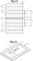
- FIGS. 11 to 13 illustrate a fourth embodiment of the IC sheet according to the present invention, and in the present embodiment, an exterior sheet 42 is stacked on each of the outer surfaces of the upper and lower cover sheets 4 and 3 of the IC sheet 1 of the second embodiment.
- Each exterior sheet 42 includes a printing sheet 43 which is disposed on the side of the cover sheet 3 or 4 and on which a pattern or the like is printed and a protective sheet 44 which protects an outer surface (printing surface) of the printing sheet 43.
- the protective sheet 44 includes a transparent sheet body, and a pattern or the like of the printing sheet 43 can be visually recognized through the protective sheet 44.
- each printing sheet 43 is preferably 0.1 to 0.2 mm, and the thickness dimension of each protective sheet 44 is preferably 0.05 to 0.1 mm.
- the thickness dimension of the printing sheet 43 is set to 0.15 mm, and the thickness dimension of the protective sheet 44 is set to 0.05 mm. Therefore, the thickness dimension of the entire IC sheet 1 is formed to be about 0.77 mm.
- the IC sheet 1 of the present embodiment is configured as a non-contact IC card 45 conforming to the JIS standard by stacking the exterior sheets 42 on the upper and lower surfaces of the IC sheet 1.
- the non-contact IC card 45 including the IC sheet 1 of the present embodiment the non-contact IC card 45 having excellent security can be obtained.
- the exterior sheets 42 are stacked on the upper and lower surfaces of the IC sheet 1, the strength as the non-contact IC card 45 is secured by the IC sheet 1.
- the degree of freedom of the sheet material that can be used for the printing sheet 43 and the protective sheet 44, which are the exterior sheet 42, increases, and accordingly, the selection range of the form of printing that can be performed increases, so that the decorativeness and design of the non-contact IC card 45 can be improved.
- the IC sheet 1 can also be applied to other uses having different thickness standards.
- the IC sheet 1 of each of the first embodiment and the third embodiment can also be configured as the non-contact IC card 45 by disposing the printing sheets 43 and the protective sheets 44.
- the polycarbonate forming both the cover sheets 3 and 4 may be, for example, environmentally friendly polycarbonate called bio-polycarbonate using plant-derived raw material or the like.
- polycarbonate having biodegradability such as soil degradability, water degradability, or marine degradability may be used.
- copolymerized polycarbonate produced by reacting an isosorbide skeleton (cyclic diol), a diol mixture, and diphenyl carbonate (DPC) can be mentioned.
- the polycarbonate may be any biodegradable polycarbonate, and is not limited to the copolymerized polycarbonate.
- polycarbonate having no biodegradability can also be used.
- the support sheet 10 includes the two base fabrics 14 and 15, but may include one nonwoven fabric.
- fibers are entangled in a state of including the IC chip 7 and the antenna 8 to form the support sheet 10 including a nonwoven fabric, or an easily softenable layer softened at a temperature lower than that of the support sheet 10 is formed on the upper surface or the lower surface of the support sheet 10, and the IC chip 7 and the antenna 8 are fixed to the easily softenable layer.
- the support sheet 10 (base fabrics 14 and 15) may include polycarbonate.
- the support sheet 10 can include a nonwoven fabric in which a large number of independent holes are opened, and as material of the support sheet 10 in this case, polycarbonate or the materials described in the above embodiments can be used.
- material of the support sheet 10 in this case, polycarbonate or the materials described in the above embodiments can be used.
- a film body or a sheet body provided with a large number of independent holes can be mentioned.
- the film body or the sheet body can include polyvinyl chloride (PVC), polyethylene terephthalate (PET, PET-G), polyethylene naphthalate (PEN), or the like.
- the antenna 8 may be formed by screen printing, etching, or the like on the surface of a film or sheet including polyvinyl chloride (PVC), polyethylene terephthalate (PET, PET-G), polyethylene naphthalate (PEN), or the like. In this case, it is preferable to provide a large number of holes in the film or the sheet except the portion where the antenna 8 is formed.
- the configuration such as the number and thickness dimensions of the sheets forming the upper and lower cover sheets 4 and 3 is not limited to the configurations of the above embodiments.
- the upper and lower cover sheets 4 and 3 may be disposed upside down.
- the planar size of the support sheet 10 (inlet 2) can be formed smaller than the planar size of the IC sheet 1 to be manufactured. In this case, by arranging the center of the inlet 2 in the plane so as to coincide with the center of the IC sheet 1, the support sheet 10 (inlet 2) can be well prevented from being exposed on the outer surface of the IC sheet 1. Note that in the region on the peripheral edge side of the IC sheet 1 where the support sheet 10 does not exist, the upper cover sheet 4 and the lower cover sheet 3 are directly welded.
- the IC sheet according to the present invention can contribute to Goal 9 (Industry, Innovation, and Infrastructure) and Goal 12 (Responsible Consumption and Production) of Sustainable Development Goals (SDGs) proposed by the United Nations.
- the cover sheets 4 and 3 can be reliably prevented from peeling off from the inlet 2.
- the IC sheet of the present invention can be manufactured by disposing the upper and lower cover sheets 3 and 4 so as to sandwich the inlet 2 therebetween and then softening the upper and lower cover sheets 4 and 3 by hot pressing. Therefore, as in a form in which the inlet and the cover sheet are joined with an adhesive, an adhesive application process is unnecessary, and it is possible to prevent productivity of the IC sheet from being lowered.
- the IC sheet of the present invention it is possible to reliably prevent the cover sheets 3 and 4 from peeling off from the inlet 2 without lowering productivity.
- polycarbonate having mechanical strength superior to that of conventional amorphous polyethylene terephthalate as material of the upper and lower cover sheets 4 and 3
- the IC sheet having more excellent mechanical strength (flexural strength and impact resistance) can be obtained. It is also possible to reduce the thickness dimension.
- the support sheet 10 in the case of trying to forcibly peel the cover sheets 4 and 3 from the inlet 2, the support sheet 10 is torn and the inlet 2 is destroyed, so that it is impossible to take out the IC chip 7 including the antenna 8 in a sound state, and the IC sheet having excellent security can be obtained.
- the total thickness dimension (T1 + T2) of both the thickness dimensions T1 and T2 is preferably set to 0.35 mm or more and 0.5 mm or less. This is because if the total thickness dimension of the upper and lower cover sheets 3 and 4 is less than 0.35 mm, the strength required for the IC sheet cannot be secured even with polycarbonate having high mechanical strength, and the resistance to bending and the impact resistance are insufficient. In addition, when the total thickness dimension of the upper and lower cover sheets 3 and 4 exceeds 0.5 mm, required mechanical strength can be sufficiently satisfied, but flexibility is lost.
- the over sheet 28 including a sheet body including resin as material is disposed on the outer surface of the lower cover sheet 3 and/or the outer surface of the upper cover sheet 4, for example, the over sheet 28 is disposed such that the stretching direction of the over sheet 28 intersects (is orthogonal to) the stretching direction of the upper and lower cover sheets 4 and 3, whereby strength and flexibility against bending can be substantially uniformly exerted against deformation in all directions.
- the over sheet 28 including resin material having a tensile strength higher than that of polycarbonate the characteristics of the materials such as securing the flexural strength by the upper and lower cover sheets 4, 3 and securing the tensile strength by the over sheet 28 can be exhibited in a composite manner.
- it is possible to impart appropriate mechanical strength to the IC sheet according to the use mode by selecting the stretching direction of the over sheet 28 or the resin material of the over sheet 28.
- the relief portion 24 including a recess is formed in the lower cover sheet 3, and the IC chip 7 is accommodated in the relief portion 24 in a state where the support sheet 10 and the cover sheets 4 and 3 are stacked, it is possible to effectively prevent the IC chip 7 from being damaged by being compressed by the upper and lower cover sheets 4 and 3 at the time of hot pressing in the manufacture of the IC sheet 1.
- the lower cover sheet 3 includes the lower base sheet 18 and the lower seal sheet 19 and the relief portion 24 is formed by the lower through hole 20 formed in the lower base sheet 18 and the lower seal sheet 19 closing the lower through hole 20, the relief portion 24 can be more easily formed in the lower cover sheet 3 as compared with a case where a recess is formed in one sheet body to form the relief portion 24. This is because cutting or the like is required in the case of forming a recess in the sheet body, but a through-hole can be easily formed by punching out the sheet body, and the recess can be formed by closing one of the openings of the hole by hot pressing.
- the lower seal sheet 19 is formed in a flat plate shape thinner than the lower base sheet 18, an increase in thickness due to the two-layer structure of the lower cover sheet 3 can be suppressed, which can contribute to thinning of the IC sheet 1. Furthermore, if the lower cover sheet 3 has a two-layer structure, for example, by stacking uniaxially stretched sheet bodies such that the stretching directions of the lower base sheet 18 and the lower seal sheet 19 intersect (are orthogonal to) each other, strength and flexibility against bending can be substantially uniformly exerted against deformation in all directions as compared with a case where the lower cover sheet 3 has a single-layer structure.
- the lower cover sheet 3 includes the lower base sheet 18 and the lower seal sheet 19
- the upper cover sheet 4 includes the upper base sheet 27 and the upper seal sheet 39
- the relief portion 24 is formed by both the through holes 20 and 40 formed in the upper and lower base sheets 18 and 27 and the seal sheets 19 and 39 closing the through holes 20 and 40
- the relief portion 24 having a recessed shape can be more easily formed in the upper and lower cover sheets 4 and 3 as compared with a case where recesses are formed in the upper and lower sheet bodies to form the relief portion 24.
- the lower seal sheet 19 is formed in a flat plate shape thinner than the lower base sheet 18 and the upper seal sheet 39 is formed in a flat plate shape thinner than the upper base sheet 27, it is possible to suppress an increase in thickness due to the two-layer structure of each of the upper and lower cover sheets 3 and 4, which can contribute to thinning of the IC sheet 1.
- each of the upper and lower cover sheets 4 and 3 has a two-layer structure
- the lower base sheet 18, the lower seal sheet 19, the upper base sheet 27, and the upper seal sheet 39 each include a uniaxially stretched sheet body and are arranged such that the stretching directions of the two (the lower base sheet 18 and the lower seal sheet 19 intersect (are orthogonal to) each other and the stretching directions of the two (the upper base sheet 27 and the upper seal sheet 39) intersect (are orthogonal to) each other, strength and flexibility against bending can be substantially uniformly exhibited against deformation in all directions as compared with a case where the upper and lower cover sheets 4 and 3 have a single-layer structure.
- the passport 36 including the IC sheet 1 as described above, since the IC sheet 1 is thinner than a non-contact IC card conforming to the standard, even in a case where the IC sheet 1 is enclosed in the passport 36, the passport 36 can be prevented from being bulky due to the IC sheet 1.
- the non-contact IC card 45 including the IC sheet 1 as described above, the non-contact IC card 45 having excellent security can be obtained.
- the exterior sheet 42 is stacked on at least one of the upper and lower surfaces of the IC sheet 1, since the strength as the non-contact IC card 45 is secured by the IC sheet 1, the degree of freedom of the sheet material that can be used for the exterior sheet 42 increases, and the selection range of the form of printing that can be performed is widened accordingly, so that decorativeness and designability of the non-contact IC card 45 can be enhanced.
Landscapes
- Engineering & Computer Science (AREA)
- Microelectronics & Electronic Packaging (AREA)
- Computer Hardware Design (AREA)
- Physics & Mathematics (AREA)
- General Physics & Mathematics (AREA)
- Theoretical Computer Science (AREA)
- Manufacturing & Machinery (AREA)
- Textile Engineering (AREA)
- Credit Cards Or The Like (AREA)
Abstract
To reliably prevent cover sheets from peeling off from an inlet without lowering productivity even in a case where polycarbonate is selected as material of the cover sheets in an IC sheet including the inlet and the cover sheets disposed on and under the inlet. An IC sheet 1 of the present invention includes: an inlet 2 including an IC chip 7, an antenna 8 that is connected to the IC chip 7, and a support sheet 10 that includes a nonwoven fabric and holds the IC chip 7 and the antenna 8; and cover sheets 3 and 4 that include polycarbonate and are disposed under and on the inlet 2, respectively. Polycarbonate resin constituting the cover sheets 3 and 4 is solidified in a state of entering between fibers of the nonwoven fabric of the support sheet 10, so that the cover sheets 3 and 4 and the support sheet 10 are integrated.
Description
- The present invention relates to an IC sheet incorporating a non-contact readable and writable IC chip, and a passport and a non-contact IC card including the IC sheet.
- An IC sheet in which an IC chip is built in a sheet body is often used for, for example, a transportation IC card. The thickness of such an IC sheet having a card size is formed to be about 0.76 mm conforming to the standard of the non-contact IC card defined in JIS. In recent years, an IC sheet incorporating an IC chip is also used in, for example, a passport, and in particular, in a booklet-shaped passport, the IC sheet is required to be thinner than an IC sheet used for a transportation IC card in order to prevent bulkiness due to the IC sheet.
- As an example of the IC sheet, for example,
Patent Literature 1 by the present applicant can be cited. The IC sheet described inPatent Literature 1 includes an inlet in which an IC chip and an antenna (antenna coil) are held on a support sheet (base sheet), two cover sheets disposed on the front side (upper side) of the inlet, and one cover sheet disposed on the back side (lower side). The inlet and the cover sheets are integrated by hot pressing in a state where they are stacked. - Patent Literature 1:
JP 2015-184774 A - In the IC card according to
Patent Literature 1, amorphous polyethylene terephthalate (PET-G) is used as material of the cover sheet. The reason why amorphous polyethylene terephthalate (PET-G) is used as the material of the cover sheet as described above is that amorphous polyethylene terephthalate (PET-G) has the strength required for an IC card and that the workability of hot pressing in manufacturing is taken into consideration. However, if the thickness dimension of the cover sheet including amorphous polyethylene terephthalate (PET-G) is reduced, there is a disadvantage that the strength is insufficient. - The above-mentioned problem of insufficient strength can be solved by using polycarbonate (PC) as the material of the cover sheet. That is, if the material of the cover sheet is polycarbonate, sufficient strength can be obtained even in a case where the thickness of the cover sheet is relatively thin. This is because polycarbonate is more excellent in mechanical strength (flexural strength and impact resistance) than amorphous polyethylene terephthalate. However, since polycarbonate is inferior in adhesiveness (heat weldability) to polyethylene terephthalate, when the inlet and the cover sheet are integrated by hot pressing, peeling easily occurs between the two (the inlet and the cover sheet). This problem can be solved by using an adhesive when the inlet and the cover sheet are integrated, but in that case, a process of applying the adhesive is required in manufacturing, and productivity is lowered. In addition, since the thickness dimension increases by the amount of the formed adhesive layer, there is a limit to thinning of the IC card.
- The present invention has been made to solve the above problems, and it is an object of the present invention to reliably prevent cover sheets from peeling off from an inlet without lowering productivity even in a case where polycarbonate is selected as material of the cover sheets in an IC sheet including the inlet and the cover sheets disposed on and under the inlet.
- An object of the present invention is to prevent a passport mounted with an IC sheet from being bulky due to the IC sheet.
- An object of the present invention is to obtain a non-contact IC card having excellent security and high decorativeness and designability.
- The present invention is directed to an IC sheet including: an
inlet 2 including anIC chip 7, anantenna 8 that is connected to theIC chip 7, and asupport sheet 10 that includes a nonwoven fabric and holds theIC chip 7 and theantenna 8; andcover sheets inlet 2, respectively. Then, polycarbonate resin constituting thecover sheets support sheet 10, so that thecover sheets support sheet 10 are integrated. - When a thickness dimension of the
lower cover sheet 3 is denoted by T1 and a thickness dimension of theupper cover sheet 4 is denoted by T2, a total thickness dimension of the thickness dimension T1 and the thickness dimension T2 is preferably set to 0.35 mm or more and 0.5 mm or less. - The minimum dimension of each of the thickness dimension T1 of the
lower cover sheet 3 and the thickness dimension T2 of theupper cover sheet 4 is preferably set to 0.05 mm or more. - An
over sheet 28 including a sheet body including resin as material is disposed on an outer surface of thelower cover sheet 3 and/or an outer surface of theupper cover sheet 4. - A
relief portion 24 including a recess is formed in thelower cover sheet 3, and theIC chip 7 is accommodated in therelief portion 24 in a state where thesupport sheet 10 and both thecover sheets - The
lower cover sheet 3 includes alower base sheet 18 that has a flat plate shape and in which a lower throughhole 20 is formed, and alower seal sheet 19 that has a flat plate shape and has a thickness smaller than a thickness of thelower base sheet 18. Thelower base sheet 18 is disposed on thesupport sheet 10, thelower seal sheet 19 is disposed on thelower base sheet 18, and the lower throughhole 20 and thelower seal sheet 19 that closes the lower throughhole 20 form therelief portion 24. - The
lower cover sheet 3 includes alower base sheet 18 that has a flat plate shape and in which a lower throughhole 20 is formed, and alower seal sheet 19 that has a flat plate shape and has a thickness smaller than a thickness of thelower base sheet 18. Thelower base sheet 18 is disposed on thesupport sheet 10, and thelower seal sheet 19 is disposed on thelower base sheet 18. Theupper cover sheet 4 includes anupper base sheet 27 that has a flat plate shape and in which an upper throughhole 40 is formed, and anupper seal sheet 39 that has a flat plate shape and has a thickness smaller than a thickness of theupper base sheet 27. Theupper base sheet 27 is disposed on thesupport sheet 10, and theupper seal sheet 39 is disposed on theupper base sheet 27. Both the throughholes seal sheets holes relief portion 24. - A passport of the present invention includes the
IC sheet 1 described in any one of the above. - A non-contact IC card of the present invention includes the
IC sheet 1 described in any one of the above. - An
exterior sheet 42 is stacked on at least one of an upper surface or a lower surface of theIC sheet 1. - According to the IC sheet of the present invention, since the polycarbonate resin constituting the upper and
lower cover sheets cover sheets cover sheets support sheet 10, so that the fibers of the nonwoven fabric and the polycarbonate resin can be firmly joined to firmly integrate the three parts (the upper andlower cover sheets inlet 2 is sandwiched between the upper andlower cover sheets inlet 2 and thecover sheets cover sheets inlet 2. In addition, the IC sheet of the present invention can be manufactured by disposing the upper andlower cover sheets inlet 2 therebetween and then softening the upper andlower cover sheets cover sheets inlet 2 without lowering productivity. In addition, by using polycarbonate having mechanical strength superior to that of conventional amorphous polyethylene terephthalate as material of the upper andlower cover sheets cover sheets inlet 2, thesupport sheet 10 is torn and theinlet 2 is destroyed, so that it is impossible to take out theIC chip 7 including theantenna 8 in a sound state, and the IC sheet having excellent security can be obtained. -
-
FIG. 1 is a longitudinal cross-sectional view of a main part of an IC sheet according to a first embodiment of the present invention. -
FIG. 2 is a partially broken plan view of the IC sheet. -
FIG. 3 is a perspective view of an inlet. -
FIG. 4 is an exploded perspective view of the IC sheet. -
FIG. 5 is a schematic view for explaining a method for manufacturing the IC sheet. -
FIG. 6 is a perspective view illustrating a use state of the IC sheet. -
FIG. 7 is an exploded perspective view of an IC sheet according to a second embodiment of the present invention. -
FIG. 8 is a longitudinal cross-sectional view of the IC sheet. -
FIG. 9 is an exploded perspective view of an IC sheet according to a third embodiment of the present invention. -
FIG. 10 is a longitudinal cross-sectional view of the IC sheet. -
FIG. 11 is an exploded perspective view of an IC sheet according a fourth embodiment of the present invention. -
FIG. 12 is a longitudinal cross-sectional view of the IC sheet. -
FIG. 13 is a perspective view illustrating a use state of the IC sheet. - (First embodiment)
FIGS. 1 to 6 illustrate a first embodiment of an IC sheet according to the present invention. Front and rear, left and right, and top and bottom in the present embodiment follow intersecting arrows illustrated inFIG. 4 and indications of front and rear, left and right, top and bottom denoted near the respective arrows, and the same applies to a second embodiment and the subsequent embodiments. Note that the top-bottom direction corresponds to the thickness direction of the IC sheet, and the dimensions such as the thickness in each drawing are not actually illustrated but schematically illustrated. - In
FIG. 2 , anIC sheet 1 mainly includes aninlet 2, alower cover sheet 3 disposed on the lower side of theinlet 2, and anupper cover sheet 4 disposed on the upper side of theinlet 2. TheIC sheet 1 can be formed in a planar size having a front-rear dimension of 54 to 88 mm and a left-right dimension of 86 to 125 mm. In the present embodiment, theIC sheet 1 is formed to have a front-rear dimension of about 54 mm and a left-right dimension of about 86 mm, which are the same as the non-contact IC card standards defined in JIS. Note that the thickness dimension is 0.76 mm according to the standard of the non-contact IC card, but it is desired to further reduce the thickness of theIC sheet 1 enclosed in a booklet-shaped passport. - As illustrated in
FIGS. 2 and 3 , theinlet 2 includes anIC chip 7 on which information is recorded, a loop coil-shapedantenna 8 connected to theIC chip 7, achip base 9 that supports theIC chip 7, asupport sheet 10 that holds theIC chip 7 and theantenna 8, and the like. TheIC chip 7 has a square shape in which each side portion has a dimension of 3.0 mm in a plan view, and a pair ofterminals IC chip 7 including the terminal 11 is preferably 0.3 mm or less, and more preferably 0.05 mm or more and 0.2 mm or less. The thickness dimension of theIC chip 7 of the present embodiment is formed to be 0.05 mm. - The
antenna 8 includes a copper wire having a wire diameter of 0.02 to 0.2 mm and having a surface coated with an insulating coating, and one copper wire is wound in a quadrangular spiral shape, and wire end portions are electrically connected to theterminals 11 of theIC chip 7, respectively. The number of turns of theantenna 8 is determined in accordance with the characteristics of theIC chip 7. TheIC chip 7 is driven by the electromotive force generated in theantenna 8 disposed in the magnetic field radiated from a reader/writer, not illustrated, as a power source, and transmits and receives information to and from the reader/writer via theantenna 8. - The
chip base 9 is formed to be one size larger than theIC chip 7 in plan view, and is provided to reinforce theIC chip 7 and prevent damage of theIC chip 7. TheIC chip 7 is bonded and fixed to the upper surface of thechip base 9. Thechip base 9 preferably includes a metal thin plate having a thickness dimension (top-bottom dimension) two to three times that of theIC chip 7, and the thickness dimension of thechip base 9 of the present embodiment is 0.12 mm. - As illustrated in
FIG. 3 , thesupport sheet 10 is formed by stacking alower base fabric 14 and anupper base fabric 15 each including nonwoven fabric. TheIC chip 7 including thechip base 9 and theantenna 8 are supported in a state of being sandwiched between the upper andlower base fabrics lower base fabrics IC chip 7 and theantenna 8 are reliably positioned and held between the twobase fabrics inlet 2, a thickness dimension of a region (minimum thickness dimension region) whose thickness direction includes the support sheet 10 (lower base fabric 14 + upper base fabric 15) is preferably formed to be 0.1 to 0.2 mm. In addition, it is preferable that a thickness dimension of a region (maximum thickness dimension region) whose thickness direction includes theIC chip 7, theantenna 8, thechip base 9, and thesupport sheet 10 is formed to be 0.3 to 0.6 mm. In the present embodiment, thelower base fabric 14 and theupper base fabric 15 of thesupport sheet 10 each includes a nonwoven fabric having a thickness dimension of 0.1 mm, and the thickness dimension of the minimum thickness dimension region is formed to be 0.15 mm. - As the fibers constituting the upper and
lower base fabrics lower base fabrics lower base fabrics - As illustrated in
FIGS. 1 and4 , thelower cover sheet 3 disposed on the lower side (back side) of theinlet 2 includes alower base sheet 18 disposed under thelower base fabric 14 of thesupport sheet 10 and alower seal sheet 19 disposed under thelower base sheet 18. Each of thesheets lower base sheet 18 is formed in a flat plate shape in which a lower throughhole 20 vertically penetrating is opened, and thelower seal sheet 19 is formed in a flat plate shape without a hole or the like. The lower throughhole 20 is provided at a position corresponding to theIC chip 7 of theinlet 2. In a state where thelower base sheet 18 and thelower seal sheet 19 are stacked, the lower opening portion of the lower throughhole 20 is closed by thelower seal sheet 19, and the lower throughhole 20 is configured as a recess opened upward. This recess functions as arelief portion 24 in which theIC chip 7 supported by thechip base 9 is accommodated when the upper andlower cover sheets inlet 2. - The
upper cover sheet 4 disposed on the upper side (front side) of theinlet 2 includes anupper base sheet 27 disposed on theupper base fabric 15 of thesupport sheet 10. Theupper base sheet 27 includes polycarbonate (PC) as material, and theupper base sheet 27 is formed in a flat plate shape having no hole or the like. - In
FIG. 1 , when a thickness dimension of thelower cover sheet 3 is denoted by T1 and a thickness dimension of theupper cover sheet 4 is denoted by T2, a total thickness dimension of the thickness dimension T1 and the thickness dimension T2 is preferably set to 0.35 mm or more and 0.5 mm or less, and is more preferably set to 0.35 mm or more and 0.45 mm or less. In addition, a thickness dimension T3 of thelower base sheet 18 constituting thelower cover sheet 3 is preferably 0.15 mm or more and 0.26 mm or less, and a thickness dimension T4 of thelower seal sheet 19 is preferably 0.05 mm or more and 0.1 mm or less. Furthermore, a thickness dimension T5 of theupper base sheet 27 constituting the upper cover sheet is preferably 0.05 mm or more and 0.1 mm or less. - In the present embodiment, the thickness dimension T3 of the
lower base sheet 18 is set to 0.2 mm, and the thickness dimension T4 of thelower seal sheet 19 is set to 0.085 mm. In addition, the thickness dimension T5 of theupper base sheet 27 is set to 0.085 mm. Therefore, the thickness dimension T1 of thelower cover sheet 3 is 0.285 mm, the thickness dimension T2 of theupper cover sheet 4 is 0.085 mm, and the total thickness dimension (T1 + T2) of the upper andlower cover sheets - Over
sheets 28 are stacked on outer surfaces of the upper andlower cover sheets sheet 28A (28) is disposed on the lower side of thelower seal sheet 19, and an upper oversheet 28B (28) is disposed on the upper side of theupper base sheet 27. Each of the upper and lower oversheets sheet 28A and a thickness dimension T7 of the upper oversheet 28B is preferably set to 0.05 mm or more and 0.1 mm or less. In the present embodiment, the thickness dimension T6 of the lower oversheet 28A is set to 0.05 mm, and the thickness dimension T7 of the upper oversheet 28B is set to 0.05 mm. - Sheet bodies including polycarbonate and forming the upper and
lower cover sheets sheets sheets lower base sheet 18, arranged in the front-rear direction in thelower seal sheet 19, and arranged in the left-right direction in the lower oversheet 28A. In addition, in theupper base sheet 27, the stretching direction is arranged in the front-rear direction, and in the upper oversheet 28B, the stretching direction is arranged in the left-right direction. In this way, by stacking the sheets so that the stretching directions intersect (are orthogonal to) each other, strength and flexibility against bending can be substantially uniformly exerted against deformation in all directions. - The
IC sheet 1 is formed by integrating theinlet 2, the upper andlower cover sheets sheets support sheet 10 and thesheets IC sheet 1. In the manufacture of theIC sheet 1, first, thelower base sheet 18, thelower seal sheet 19, and the lower oversheet 28A are stacked in the described order on the lower side of theinlet 2, and theupper base sheet 27 and the upper oversheet 28B are stacked in the described order on the upper side of theinlet 2. - Next, the stacked sheet group is set between upper and
lower heating molds hot press apparatus 31 illustrated inFIG. 5 . In this state, while heating theheating molds upper heating mold 32 is moved downward and pressed against thelower heating mold 33, and the upper andlower cover sheets sheets inlet 2 are held in a pressurized state for a predetermined time. The upper andlower cover sheets sheets lower base sheets support sheet 10, the polycarbonate resin enters between the fibers of the upper andlower base fabrics support sheet 10, the upper andlower base fabrics sheets lower base fabrics support sheet 10 are near the center of the sheet group, thesheets lower base fabrics base sheets lower base fabrics - When heating by the
hot press apparatus 31 is released after holding for a predetermined time, curing of each of thesheets lower base sheets 27 and 18 (upper andlower cover sheets 4 and 3) solidifies in a state of entering between fibers of the nonwoven fabric of thesupport sheet 10, so that theinlet 2 and both thebase sheets respective sheets inlet 2 and thesheets hot press apparatus 31 after the pressurization by theupper heating mold 32 is released. Finally, theIC sheet 1 is obtained by punching or cutting the taken-out blank body into a normal plane size using a punching apparatus or a cutting apparatus (not illustrated). - The upper and
lower base fabrics support sheet 10 are compressed in the thickness direction by heating and pressurization by thehot press apparatus 31 at the time of manufacturing, and the upper andlower base sheets lower base fabrics lower base sheets support sheet 10 is absorbed by the thickness dimensions T3 and T5 of the upper andlower base sheets IC sheet 1 is formed to be 0.47 mm, which is the same as the total thickness dimension of the upper andlower cover sheets sheets FIG. 1 , the thickness is left in order to facilitate understanding of the stacked state. - In the manufacture of the
IC sheet 1 by hot pressing, in order to strengthen the welding between thelower base sheet 18 and thelower seal sheet 19, between thelower seal sheet 19 and the lower oversheet 28A, and between theupper base sheet 27 and the upper oversheet 28B in contact with each other, it is preferable that the front and back surfaces of the sheet bodies forming thelower base sheet 18, thelower seal sheet 19, theupper base sheet 27, the lower oversheet 28A, and the upper oversheet 28B are not smooth but slightly roughened. As a result, it is possible to increase the area of close contact at the time of welding, and further, it is possible to prevent deterioration of work efficiency due to mutual attraction by static electricity when the sheet bodies are stacked as the group of sheets. Note that the lower surface of the lower oversheet 28A and the upper surface of the upper oversheet 28B are softened at the time of hot pressing, and the surface shapes of the upper andlower heating molds heating molds IC sheet 1 are smooth surfaces. -
FIG. 6 illustrates an example in which theIC sheet 1 is mounted on a passport (booklet) 36. TheIC sheet 1 is enclosed inside a predetermined page constituting thepassport 36, specifically, a data page on which a face photograph and personal information are printed. In theIC chip 7, information on the possessor matching the content described in the data page at the time of creating thepassport 36 is recorded. By accessing theIC chip 7 with a dedicated reader/writer, the information on the possessor described in the data page of thepassport 36 can be compared with the information on the possessor recorded in theIC chip 7, and the authenticity of thepassport 36 can be determined. In addition, since theIC sheet 1 is thinner than a non-contact IC card conforming to the standard, even in a case where theIC sheet 1 is mounted on the passport 36 (enclosed inside the data page), thepassport 36 can be prevented from being bulky due to theIC sheet 1. Note that, althoughFIG. 6 illustrates an example in which theIC sheet 1 is enclosed in the data page, theIC sheet 1 may be enclosed in the front/back cover (cover page) or a page (center page) other than the data page. - As described above, in the
IC sheet 1 of the present embodiment, since the polycarbonate resin constituting the upper andlower cover sheets cover sheets cover sheets support sheet 10, so that the fibers of the nonwoven fabric and the polycarbonate resin can be firmly joined to firmly integrate the three parts (the upper andlower cover sheets inlet 2 is sandwiched between the upper andlower cover sheets support sheet 10 and the polycarbonate resin are bonded, peeling between theinlet 2 and thecover sheets cover sheets inlet 2, thesupport sheet 10 is torn and theinlet 2 is destroyed, so that it is impossible to take out theIC chip 7 including theantenna 8 in a sound state. Therefore, the IC sheet having excellent security can be obtained. As described above, in order to cause thecover sheets support sheet 10, thesoftened cover sheets lower cover sheets lower cover sheets lower cover sheets IC sheet 1 of the present embodiment, it is possible to reliably prevent thecover sheets inlet 2 without lowering the productivity while using polycarbonate having better mechanical strength than conventional amorphous polyethylene terephthalate as the material of the upper andlower cover sheets - If the total thickness dimension (T1 + T2) of the thickness dimensions T1 and T2 of the upper and
lower cover sheets lower cover sheets IC sheet 1, the total thickness dimension (T1 + T2) of the thickness dimensions T1 and T2 of the upper andlower cover sheets lower cover sheets - If the minimum dimension of each of the thickness dimension T1 of the
lower cover sheet 3 and the thickness dimension T2 of theupper cover sheet 4 is less than 0.05 mm, most of thelower cover sheet 3 or theupper cover sheet 4 enters between the fibers of thesupport sheet 10 at the time of hot pressing in manufacturing, so that even in a case where the upper andlower cover sheets IC chip 7 and theantenna 8 may be seen through, and there is a concern of security that concealability is poor. In addition, the nonwoven fabric of thesupport sheet 10 may exposed on the surface of theIC sheet 1, so that the appearance may be deteriorated. Therefore, the minimum dimension of each of the thickness dimension T1 of thelower cover sheet 3 and the thickness dimension T2 of theupper cover sheet 4 is preferably set to 0.05 mm or more. - Since the
IC chip 7 is accommodated in therelief portion 24 including the recess formed in thelower cover sheet 3, it is possible to effectively prevent damage of theIC chip 7 due to compression by the upper andlower cover sheets IC sheet 1. In addition, it is possible to prevent deterioration in appearance due to deterioration in smoothness of the surface of theIC sheet 1 caused by slight expansion of the portion where theIC chip 7 exists due to a difference in the amount of shrinkage due to the difference in thickness between the portion where theIC chip 7 exists and the other portion after hot pressing in a case where therelief portion 24 is not provided. - Since the
relief portion 24 is formed by the lower throughhole 20 formed in thelower base sheet 18 and thelower seal sheet 19 closing the lower throughhole 20, therelief portion 24 having a recessed shape can be easily formed in thelower cover sheet 3 as compared with a case where a recess is formed in one sheet body to form therelief portion 24. This is because cutting or the like is required in the case of forming a recess in the sheet body, but a through-hole can be easily formed by punching out the sheet body, and the recess can be formed by closing one of the openings of the hole by hot pressing. In addition, if thelower seal sheet 19 is formed in a flat plate shape thinner than thelower base sheet 18, an increase in thickness due to the two-layer structure of thelower cover sheet 3 can be suppressed, which can contribute to thinning of theIC sheet 1. Furthermore, since thelower cover sheet 3 has a two-layer structure of thelower base sheet 18 and thelower seal sheet 19, and both thesheets sheets lower cover sheet 3 has a single-layer structure. - At the time of manufacturing the
IC sheet 1, thelower seal sheet 19 may be stacked on the upper side of thelower base sheet 18 and temporarily fixed by welding, and both the temporarily fixedsheets lower heating mold 33. In this case, by making the thickness dimension T3 of thelower base sheet 18 thicker than the thickness dimension T4 of thelower seal sheet 19, it is possible to perform temporary fixing by welding of both thesheets IC sheet 1 can be improved. In addition, if the thickness dimension T3 of thelower base sheet 18 is made larger than the thickness dimension T4 of thelower seal sheet 19, for example, handling becomes easy at the time of welding of both thesheets sheets inlet 2, and the like, and work efficiency can be improved. - In the
IC sheet 1 of the present embodiment, theinlet 2 is formed as one assembly by holding theIC chip 7, thechip base 9 supporting theIC chip 7, and theantenna 8 between both thebase fabrics support sheet 10. As described above, according to theinlet 2 in which theIC chip 7, theantenna 8, and thechip base 9 are held between thebase fabrics inlet 2 is handled at the time of manufacturing theIC sheet 1 or the like, thebase fabrics IC chip 7 and theantenna 8 from coming into contact with other objects. According to thebase fabrics IC chip 7 and theantenna 8 due to impact of contact or the like by cushioning properties derived from the nonwoven fabric. Theinlet 2 configured as an assembly is also excellent in that handling at the time of manufacturing theIC sheet 1 is facilitated. - When the
IC sheet 1 is formed including theinlet 2, the outer surfaces of the support sheet 10 (base fabrics 14 and 15) portion vertically sandwiching theIC chip 7, thechip base 9, and theantenna 8 accommodated in therelief portion 24 may be in either a state of being separated from or in contact with the upper base sheet 27 (upper cover sheet 4) and thelower seal sheet 19 defining the upper and lower surfaces of therelief portion 24. In a case where the outer surfaces of thesupport sheet 10 are separated from theupper base sheet 27 and thelower seal sheet 19 that define the upper and lower surfaces of therelief portion 24, theIC chip 7, thechip base 9, and theantenna 8 can be held in a dangling manner in therelief portion 24. Therefore, when theIC sheet 1 is deformed in a case where theIC sheet 1 is bent, or an impact is applied to theIC sheet 1, the stress does not directly act on theIC chip 7 and theantenna 8, and damage of theIC chip 7 and theantenna 8 can be prevented. In addition, in a case where the outer surfaces of thesupport sheet 10 are in contact with theupper base sheet 27 and thelower seal sheet 19 that define the upper and lower surfaces of therelief portion 24, it is possible to prevent the outer surfaces of theIC sheet 1 facing therelief portion 24 from being recessed or inflated. In addition, when theIC sheet 1 is deformed in a case where theIC sheet 1 is bent, or an impact is applied to theIC sheet 1, the stress can be released by theentire IC sheet 1, and further, the stress can be absorbed by the cushioning property derived from thesupport sheet 10 including nonwoven fabric, so that theIC chip 7 can be prevented from being damaged. - In the
IC sheet 1 of the present embodiment, thelower base fabric 14 is separated from thelower seal sheet 19, and theupper base fabric 15 is in contact with theupper base sheet 27. Note that in the present embodiment, by adjusting the thickness dimension T3 of thelower base sheet 18, it is also possible to adopt a configuration in which the outer surfaces of the support sheet 10 (base fabrics 14 and 15) located in therelief portion 24 are in contact with theupper base sheet 27 and thelower seal sheet 19. - In the above embodiment, each of the upper and lower over
sheets sheets 28, the characteristics of the materials such as securing the flexural strength by the upper andlower cover sheets sheets 28 are exhibited in a composite manner, and theIC sheet 1 having the mechanical strength suitable for the use mode can be relatively easily obtained by selecting the resin material. - (Second embodiment)
FIGS. 7 and8 illustrate a second embodiment of the IC sheet according to the present invention. The present embodiment is different from the first embodiment in that oversheets lower cover sheets upper cover sheet 4 is different. Specifically, similarly to thelower cover sheet 3, theupper cover sheet 4 includes anupper base sheet 27 and anupper seal sheet 39. Each of thesheets upper base sheet 27 is formed in a flat plate shape in which an upper throughhole 40 vertically penetrating is opened, and theupper seal sheet 39 is formed in a flat plate shape without a hole or the like. The upper throughhole 40 is provided at a position corresponding to anIC chip 7 of aninlet 2. In a state where theupper base sheet 27 and theupper seal sheet 39 are stacked, an upper opening portion of the upper throughhole 40 is closed by theupper seal sheet 39, and the upper throughhole 40 is configured as a recess opened downward. Opposite recesses including the upper throughhole 40 and a lower throughhole 20 and formed in the upper andlower cover sheets relief portion 24 in which theIC chip 7 supported by achip base 9 is accommodated. - In the present embodiment, a thickness dimension T3 of a
lower base sheet 18 is set to 0.1 mm, and a thickness dimension T4 of alower seal sheet 19 is set to 0.085 mm. In addition, a thickness dimension T5 of theupper base sheet 27 is set to 0.1 mm, and a thickness dimension T8 of theupper seal sheet 39 is set to 0.085 mm. Therefore, a thickness dimension T1 of thelower cover sheet 3 is 0.185 mm, a thickness dimension T2 of theupper cover sheet 4 is 0.185 mm, and the total thickness dimension (T1 + T2) of the upper andlower cover sheets lower base sheet 18, thelower seal sheet 19, theupper base sheet 27, and theupper seal sheet 39 each include a uniaxially stretched sheet body, and the sheet bodies adjacent to each other are stacked so as to have different stretching directions. Since the others are similar to those of the first embodiment, the same members are denoted by the same reference numerals, and the description thereof will be omitted. The same applies to the following third and subsequent embodiment. - In the
IC sheet 1 of the present embodiment, since therelief portion 24 is formed by the upper and lower throughholes base sheets lower seal sheets holes relief portion 24 can be more easily formed in the upper andlower cover sheets lower cover sheets relief portion 24. In addition, since thelower seal sheet 19 is formed in a flat plate shape thinner than thelower base sheet 18 and theupper seal sheet 39 is formed in a flat plate shape thinner than theupper base sheet 27, it is possible to suppress an increase in thickness due to the two-layer structure of each of the upper andlower cover sheets IC sheet 1. Furthermore, since thelower base sheet 18 and thelower seal sheet 19, and theupper base sheet 27 and theupper seal sheet 39 are arranged such that the stretching directions of thelower base sheet 18 and thelower seal sheet 19 intersect (are orthogonal to) each other and the stretching directions of theupper base sheet 27 and theupper seal sheet 39 intersect (are orthogonal to) each other, strength and flexibility against bending can be substantially uniformly exerted against deformation in all directions as compared with a case where each of the upper andlower cover sheets - In the
IC sheet 1 of the present embodiment, theIC chip 7, anantenna 8, and achip base 9 are accommodated in therelief portion 24 in a state where alower base fabric 14 and thelower seal sheet 19 are separated from each other, and anupper base fabric 15 and theupper seal sheet 39 are separated from each other. Note that in the present embodiment, by adjusting the thickness dimension T3 of thelower base sheet 18 and the thickness dimension T5 of theupper base sheet 27, it is possible to adopt a configuration in which thelower base fabric 14 is in contact with thelower seal sheet 19 and theupper base fabric 15 is in contact with theupper seal sheet 39. - (Third embodiment)
FIGS. 9 and10 illustrate a third embodiment of an IC sheet according to the present invention. The present embodiment is different from the first embodiment in that the upper and lower oversheets lower cover sheets lower base sheet 18 is set to 0.2 mm, and the thickness dimension T4 of thelower seal sheet 19 is set to 0.085 mm. In addition, the thickness dimension T5 of theupper base sheet 27 is set to 0.085 mm. Therefore, a thickness dimension T1 of thelower cover sheet 3 is 0.285 mm, a thickness dimension T2 of theupper cover sheet 4 is 0.085 mm, and the total thickness dimension T3 of the thickness dimension T1 and the thickness dimension T2 is 0.37 mm. - In the present embodiment, since the total number of sheet bodies constituting an
IC sheet 1 is small, it is easy to reduce the thickness of theIC sheet 1. In addition, in hot pressing in manufacturing, since the volume of the sheet bodies to be softened is relatively small, the amount of heat required is small, and the heating time is short, so that productivity can be improved. Further, as in the present embodiment and the second embodiment described above, the over sheets 28 (28A, 28B) stacked on the outermost surfaces are not essential, and the upper andlower seal sheets upper base sheet 27 may be exposed on the outer surfaces of theIC sheet 1. - (Fourth embodiment)
FIGS. 11 to 13 illustrate a fourth embodiment of the IC sheet according to the present invention, and in the present embodiment, anexterior sheet 42 is stacked on each of the outer surfaces of the upper andlower cover sheets IC sheet 1 of the second embodiment. Eachexterior sheet 42 includes aprinting sheet 43 which is disposed on the side of thecover sheet protective sheet 44 which protects an outer surface (printing surface) of theprinting sheet 43. Theprotective sheet 44 includes a transparent sheet body, and a pattern or the like of theprinting sheet 43 can be visually recognized through theprotective sheet 44. The thickness dimension of eachprinting sheet 43 is preferably 0.1 to 0.2 mm, and the thickness dimension of eachprotective sheet 44 is preferably 0.05 to 0.1 mm. In the present embodiment, the thickness dimension of theprinting sheet 43 is set to 0.15 mm, and the thickness dimension of theprotective sheet 44 is set to 0.05 mm. Therefore, the thickness dimension of theentire IC sheet 1 is formed to be about 0.77 mm. - As described above, the
IC sheet 1 of the present embodiment is configured as anon-contact IC card 45 conforming to the JIS standard by stacking theexterior sheets 42 on the upper and lower surfaces of theIC sheet 1. As described above, according to thenon-contact IC card 45 including theIC sheet 1 of the present embodiment, thenon-contact IC card 45 having excellent security can be obtained. In addition, since theexterior sheets 42 are stacked on the upper and lower surfaces of theIC sheet 1, the strength as thenon-contact IC card 45 is secured by theIC sheet 1. Therefore, the degree of freedom of the sheet material that can be used for theprinting sheet 43 and theprotective sheet 44, which are theexterior sheet 42, increases, and accordingly, the selection range of the form of printing that can be performed increases, so that the decorativeness and design of thenon-contact IC card 45 can be improved. - As described above, by providing the
printing sheet 43 and the like and adjusting the thickness dimension of theIC sheet 1, theIC sheet 1 can also be applied to other uses having different thickness standards. TheIC sheet 1 of each of the first embodiment and the third embodiment can also be configured as thenon-contact IC card 45 by disposing theprinting sheets 43 and theprotective sheets 44. - In each of the above embodiments, the polycarbonate forming both the
cover sheets - In each of the above embodiments, the
support sheet 10 includes the twobase fabrics IC chip 7 and theantenna 8 to form thesupport sheet 10 including a nonwoven fabric, or an easily softenable layer softened at a temperature lower than that of thesupport sheet 10 is formed on the upper surface or the lower surface of thesupport sheet 10, and theIC chip 7 and theantenna 8 are fixed to the easily softenable layer. The support sheet 10 (base fabrics 14 and 15) may include polycarbonate. Moreover, thesupport sheet 10 can include a nonwoven fabric in which a large number of independent holes are opened, and as material of thesupport sheet 10 in this case, polycarbonate or the materials described in the above embodiments can be used. As a reference example of the material forming thesupport sheet 10, a film body or a sheet body provided with a large number of independent holes can be mentioned. The film body or the sheet body can include polyvinyl chloride (PVC), polyethylene terephthalate (PET, PET-G), polyethylene naphthalate (PEN), or the like. - The
antenna 8 may be formed by screen printing, etching, or the like on the surface of a film or sheet including polyvinyl chloride (PVC), polyethylene terephthalate (PET, PET-G), polyethylene naphthalate (PEN), or the like. In this case, it is preferable to provide a large number of holes in the film or the sheet except the portion where theantenna 8 is formed. The configuration such as the number and thickness dimensions of the sheets forming the upper andlower cover sheets lower cover sheets IC sheet 1 to be manufactured. In this case, by arranging the center of theinlet 2 in the plane so as to coincide with the center of theIC sheet 1, the support sheet 10 (inlet 2) can be well prevented from being exposed on the outer surface of theIC sheet 1. Note that in the region on the peripheral edge side of theIC sheet 1 where thesupport sheet 10 does not exist, theupper cover sheet 4 and thelower cover sheet 3 are directly welded. The IC sheet according to the present invention can contribute to Goal 9 (Industry, Innovation, and Infrastructure) and Goal 12 (Responsible Consumption and Production) of Sustainable Development Goals (SDGs) proposed by the United Nations. - According to the IC sheet of the present invention, since the polycarbonate resin constituting the upper and
lower cover sheets cover sheets cover sheets support sheet 10, so that the fibers of the nonwoven fabric and the polycarbonate resin can be firmly joined to firmly integrate the three parts (the upper andlower cover sheets inlet 2 is sandwiched between the upper andlower cover sheets inlet 2 and thecover sheets cover sheets inlet 2. In addition, the IC sheet of the present invention can be manufactured by disposing the upper andlower cover sheets inlet 2 therebetween and then softening the upper andlower cover sheets cover sheets inlet 2 without lowering productivity. In addition, by using polycarbonate having mechanical strength superior to that of conventional amorphous polyethylene terephthalate as material of the upper andlower cover sheets cover sheets inlet 2, thesupport sheet 10 is torn and theinlet 2 is destroyed, so that it is impossible to take out theIC chip 7 including theantenna 8 in a sound state, and the IC sheet having excellent security can be obtained. - When the thickness dimension of the
lower cover sheet 3 is denoted by T1 and the thickness dimension of theupper cover sheet 4 is denoted by T2, the total thickness dimension (T1 + T2) of both the thickness dimensions T1 and T2 is preferably set to 0.35 mm or more and 0.5 mm or less. This is because if the total thickness dimension of the upper andlower cover sheets lower cover sheets - The minimum dimension of each of the thickness dimension T1 of the
lower cover sheet 3 and the thickness dimension T2 of theupper cover sheet 4 is preferably set to 0.05 mm or more. This is because if each of the thickness dimension T1 and the thickness dimension T2 is less than 0.05 mm, most of thelower cover sheet 3 or theupper cover sheet 4 enters between the fibers of thesupport sheet 10 at the time of hot pressing in manufacturing, so that even in a case where the upper andlower cover sheets IC chip 7 and theantenna 8 are seen through, concealability is poor, and there is a concern of security. In addition, the nonwoven fabric of thesupport sheet 10 may be exposed on the surface of theIC sheet 1, so that the appearance may be deteriorated. - When the over
sheet 28 including a sheet body including resin as material is disposed on the outer surface of thelower cover sheet 3 and/or the outer surface of theupper cover sheet 4, for example, the oversheet 28 is disposed such that the stretching direction of the oversheet 28 intersects (is orthogonal to) the stretching direction of the upper andlower cover sheets sheet 28 including resin material having a tensile strength higher than that of polycarbonate, the characteristics of the materials such as securing the flexural strength by the upper andlower cover sheets sheet 28 can be exhibited in a composite manner. As described above, it is possible to impart appropriate mechanical strength to the IC sheet according to the use mode by selecting the stretching direction of the oversheet 28 or the resin material of the oversheet 28. - If the
relief portion 24 including a recess is formed in thelower cover sheet 3, and theIC chip 7 is accommodated in therelief portion 24 in a state where thesupport sheet 10 and thecover sheets IC chip 7 from being damaged by being compressed by the upper andlower cover sheets IC sheet 1. In addition, it is also possible to prevent deterioration in appearance due to deterioration in smoothness of the surface of theIC sheet 1 caused by slight expansion of the portion where theIC chip 7 exists due to a difference in the amount of shrinkage due to the difference in thickness between the portion where theIC chip 7 exists and the other portion after hot pressing in a case where therelief portion 24 is not provided. - If the
lower cover sheet 3 includes thelower base sheet 18 and thelower seal sheet 19 and therelief portion 24 is formed by the lower throughhole 20 formed in thelower base sheet 18 and thelower seal sheet 19 closing the lower throughhole 20, therelief portion 24 can be more easily formed in thelower cover sheet 3 as compared with a case where a recess is formed in one sheet body to form therelief portion 24. This is because cutting or the like is required in the case of forming a recess in the sheet body, but a through-hole can be easily formed by punching out the sheet body, and the recess can be formed by closing one of the openings of the hole by hot pressing. In addition, if thelower seal sheet 19 is formed in a flat plate shape thinner than thelower base sheet 18, an increase in thickness due to the two-layer structure of thelower cover sheet 3 can be suppressed, which can contribute to thinning of theIC sheet 1. Furthermore, if thelower cover sheet 3 has a two-layer structure, for example, by stacking uniaxially stretched sheet bodies such that the stretching directions of thelower base sheet 18 and thelower seal sheet 19 intersect (are orthogonal to) each other, strength and flexibility against bending can be substantially uniformly exerted against deformation in all directions as compared with a case where thelower cover sheet 3 has a single-layer structure. - If the
lower cover sheet 3 includes thelower base sheet 18 and thelower seal sheet 19, theupper cover sheet 4 includes theupper base sheet 27 and theupper seal sheet 39, and therelief portion 24 is formed by both the throughholes lower base sheets seal sheets holes relief portion 24 having a recessed shape can be more easily formed in the upper andlower cover sheets relief portion 24. In addition, if thelower seal sheet 19 is formed in a flat plate shape thinner than thelower base sheet 18 and theupper seal sheet 39 is formed in a flat plate shape thinner than theupper base sheet 27, it is possible to suppress an increase in thickness due to the two-layer structure of each of the upper andlower cover sheets IC sheet 1. Furthermore, when each of the upper andlower cover sheets lower base sheet 18, thelower seal sheet 19, theupper base sheet 27, and theupper seal sheet 39 each include a uniaxially stretched sheet body and are arranged such that the stretching directions of the two (thelower base sheet 18 and thelower seal sheet 19 intersect (are orthogonal to) each other and the stretching directions of the two (theupper base sheet 27 and the upper seal sheet 39) intersect (are orthogonal to) each other, strength and flexibility against bending can be substantially uniformly exhibited against deformation in all directions as compared with a case where the upper andlower cover sheets - According to the
passport 36 including theIC sheet 1 as described above, since theIC sheet 1 is thinner than a non-contact IC card conforming to the standard, even in a case where theIC sheet 1 is enclosed in thepassport 36, thepassport 36 can be prevented from being bulky due to theIC sheet 1. - According to the
non-contact IC card 45 including theIC sheet 1 as described above, thenon-contact IC card 45 having excellent security can be obtained. In addition, if theexterior sheet 42 is stacked on at least one of the upper and lower surfaces of theIC sheet 1, since the strength as thenon-contact IC card 45 is secured by theIC sheet 1, the degree of freedom of the sheet material that can be used for theexterior sheet 42 increases, and the selection range of the form of printing that can be performed is widened accordingly, so that decorativeness and designability of thenon-contact IC card 45 can be enhanced. -
- 1
- IC sheet
- 2
- Inlet
- 3
- Lower cover sheet
- 4
- Upper cover sheet
- 7
- IC chip
- 8
- Antenna
- 10
- Support sheet
- 18
- Lower base sheet
- 19
- Lower seal sheet
- 20
- Lower through hole
- 24
- Relief portion
- 27
- Upper base sheet
- 28
- Over sheet
- 39
- Upper seal sheet
- 40
- Upper through hole
- 42
- Exterior sheet
- T1
- Thickness dimension of lower cover sheet
- T2
- Thickness dimension of upper cover sheet
Claims (10)
- An IC sheet comprising:an inlet (2) including an IC chip (7), an antenna (8) that is connected to the IC chip (7), and a support sheet (10) that includes a nonwoven fabric and holds the IC chip (7) and the antenna (8); andcover sheets (3 and 4) that include polycarbonate and are disposed under and on the inlet (2), respectively,wherein polycarbonate resin constituting the cover sheets (3 and 4) is solidified in a state of entering between fibers of the nonwoven fabric of the support sheet (10), so that the cover sheets (3 and 4) and the support sheet (10) are integrated.
- The IC sheet according to claim 1, wherein when a thickness dimension of the lower cover sheet (3) is denoted by (T1) and a thickness dimension of the upper cover sheet (4) is denoted by (T2), a total thickness dimension of the thickness dimension (T1) and the thickness dimension (T2) is set to 0.35 mm or more and 0.5 mm or less.
- The IC sheet according to claim 2, wherein a minimum dimension of each of the thickness dimension (T1) of the lower cover sheet (3) and the thickness dimension (T2) of the upper cover sheet (4) is set to 0.05 mm or more.
- The IC sheet according to claim 1, wherein an over sheet (28) including a sheet body including resin as material is disposed on an outer surface of the lower cover sheet (3) and/or an outer surface of the upper cover sheet (4).
- The IC sheet according to any one of claims 1 to 4, whereina relief portion (24) including a recess is formed in the lower cover sheet (3), andthe IC chip (7) is accommodated in the relief portion (24) in a state where the support sheet (10) and both the cover sheets (3 and 4) are stacked.
- The IC sheet according to claim 5, whereinthe lower cover sheet (3) includes a lower base sheet (18) that has a flat plate shape and in which a lower through hole (20) is formed, and a lower seal sheet (19) that has a flat plate shape and has a thickness smaller than a thickness of the lower base sheet (18), the lower base sheet (18) is disposed under the support sheet (10), the lower seal sheet (19) is disposed under the lower base sheet (18), andthe lower through hole (20) and the lower seal sheet (19) that closes the lower through hole (20) form the relief portion (24).
- The IC sheet according to claim 5, whereinthe lower cover sheet (3) includes a lower base sheet (18) that has a flat plate shape and in which a lower through hole (20) is formed, and a lower seal sheet (19) that has a flat plate shape and has a thickness smaller than a thickness of the lower base sheet (18), the lower base sheet (18) is disposed under the support sheet (10), the lower seal sheet (19) is disposed under the lower base sheet (18),the upper cover sheet (4) includes an upper base sheet (27) that has a flat plate shape and in which an upper through hole (40) is formed and an upper seal sheet (39) that has a flat plate shape and has a thickness smaller than a thickness of the upper base sheet (27), the upper base sheet (27) is disposed on the support sheet (10), the upper seal sheet (39) is disposed on the upper base sheet (27), andthe relief portion (24) is formed by both the through holes (20 and 40) and the seal sheets (19 and 39) that close the through holes (20 and 40).
- A passport comprising the IC sheet (1) according to claim 1.
- A non-contact IC card comprising the IC sheet (1) according to claim 1.
- The non-contact IC card according to claim 9, wherein an exterior sheet (42) is stacked on at least one of an upper surface or a lower surface of the IC sheet (1).
Applications Claiming Priority (2)
| Application Number | Priority Date | Filing Date | Title |
|---|---|---|---|
| JP2022105016A JP2024005039A (en) | 2022-06-29 | 2022-06-29 | IC sheet, passport and contactless IC card equipped with this IC sheet |
| PCT/JP2023/023520 WO2024004922A1 (en) | 2022-06-29 | 2023-06-26 | Ic sheet, and passport and contactless ic card with ic sheet |
Publications (2)
| Publication Number | Publication Date |
|---|---|
| EP4550208A1 true EP4550208A1 (en) | 2025-05-07 |
| EP4550208A4 EP4550208A4 (en) | 2026-08-19 |
Family
ID=89383036
Family Applications (1)
| Application Number | Title | Priority Date | Filing Date |
|---|---|---|---|
| EP23831364.7A Pending EP4550208A4 (en) | 2022-06-29 | 2023-06-26 | IC film, passport and contactless IC card with the IC film |
Country Status (4)
| Country | Link |
|---|---|
| US (1) | US20260001369A1 (en) |
| EP (1) | EP4550208A4 (en) |
| JP (1) | JP2024005039A (en) |
| WO (1) | WO2024004922A1 (en) |
Family Cites Families (11)
| Publication number | Priority date | Publication date | Assignee | Title |
|---|---|---|---|---|
| JPS62134295A (en) * | 1985-12-06 | 1987-06-17 | 松下電器産業株式会社 | IC card |
| JPH10129165A (en) * | 1996-03-15 | 1998-05-19 | Hitachi Maxell Ltd | Information carrier and method of manufacturing the same |
| JP2000091494A (en) * | 1998-07-15 | 2000-03-31 | Shiima Denshi Kk | Thin electronic information equipment and method of manufacturing the same |
| JP2000113151A (en) * | 1998-10-01 | 2000-04-21 | Tomoegawa Paper Co Ltd | Label IC card |
| JP4340929B2 (en) * | 1998-10-02 | 2009-10-07 | ソニー株式会社 | Memory IC tag device |
| JP2006309603A (en) * | 2005-04-28 | 2006-11-09 | Kyodo Printing Co Ltd | Non-contact IC card |
| JP4456175B1 (en) * | 2009-10-09 | 2010-04-28 | 日本カラリング株式会社 | Composite hinge sheet for laser marking laminate for electronic passport and laser marking laminate for electronic passport and electronic passport |
| JP6261127B2 (en) | 2014-03-20 | 2018-01-17 | マクセルホールディングス株式会社 | Inlet manufacturing method |
| JP6701807B2 (en) * | 2015-09-18 | 2020-05-27 | 王子ホールディングス株式会社 | Laminate |
| JP6970927B2 (en) * | 2017-02-16 | 2021-11-24 | 大日本印刷株式会社 | Information page |
| JP7779646B2 (en) * | 2020-09-09 | 2025-12-03 | 株式会社Jvcケンウッド | Speaker diaphragm, speaker diaphragm manufacturing method, and speaker |
-
2022
- 2022-06-29 JP JP2022105016A patent/JP2024005039A/en active Pending
-
2023
- 2023-06-26 EP EP23831364.7A patent/EP4550208A4/en active Pending
- 2023-06-26 US US18/877,283 patent/US20260001369A1/en active Pending
- 2023-06-26 WO PCT/JP2023/023520 patent/WO2024004922A1/en not_active Ceased
Also Published As
| Publication number | Publication date |
|---|---|
| JP2024005039A (en) | 2024-01-17 |
| EP4550208A4 (en) | 2026-08-19 |
| US20260001369A1 (en) | 2026-01-01 |
| WO2024004922A1 (en) | 2024-01-04 |
Similar Documents
| Publication | Publication Date | Title |
|---|---|---|
| KR100421706B1 (en) | Method for making cards and cards obtained by this method | |
| TWI487622B (en) | Reinforced radio frequency identification device support and manufacturing method thereof | |
| JP4339111B2 (en) | Contactless smart card having antenna support and chip support made of fibrous material | |
| CN100575116C (en) | Method for producing a security book-size document and a security book-size document | |
| KR100998605B1 (en) | Method for manufacturing a contactless or contact / contactless hybrid chip card with improved flatness | |
| US20100130288A1 (en) | Rfid-incorporated game token and manufacturing method thereof | |
| US20080131669A1 (en) | Transponder embedded in a flexible multilayer support | |
| EP3584091B1 (en) | Information page | |
| CN107408216A (en) | Valuable or secure file with electronic circuit and for manufacturing valuable or secure file method | |
| US20260001369A1 (en) | Ic sheet, and passport and non-contact ic card including ic sheet | |
| JP7250565B2 (en) | IC card and manufacturing method thereof | |
| KR102816521B1 (en) | Three-dimensional pattern card and method of fabricating the card | |
| JPH02165997A (en) | Manufacture of card | |
| JP4649688B2 (en) | Non-contact IC card | |
| KR101535106B1 (en) | Card including ramie fabric sheet and fabricating method of the same | |
| WO2005062246A1 (en) | Identification document | |
| JP7863292B2 (en) | Laminate, laminate with IC, method for manufacturing a laminate, method for manufacturing a laminate with IC | |
| JPH10278458A (en) | Non-contact type IC card and manufacturing method thereof | |
| JP5417938B2 (en) | Non-contact IC card manufacturing method | |
| JP4459670B2 (en) | UIM with plate frame | |
| JP2025178705A (en) | Resin card medium and its manufacturing method | |
| JP6070447B2 (en) | IC card, laminated sheet, and IC card manufacturing method | |
| JP2025103997A (en) | IC sheet, IC sheet manufacturing method, inlet for IC sheet, and non-contact IC card equipped with IC sheet | |
| JP2006309775A (en) | Method of manufacturing data medium with electronic module | |
| JP2025066903A (en) | IC sheet |
Legal Events
| Date | Code | Title | Description |
|---|---|---|---|
| STAA | Information on the status of an ep patent application or granted ep patent |
Free format text: STATUS: THE INTERNATIONAL PUBLICATION HAS BEEN MADE |
|
| PUAI | Public reference made under article 153(3) epc to a published international application that has entered the european phase |
Free format text: ORIGINAL CODE: 0009012 |
|
| STAA | Information on the status of an ep patent application or granted ep patent |
Free format text: STATUS: REQUEST FOR EXAMINATION WAS MADE |
|
| 17P | Request for examination filed |
Effective date: 20241218 |
|
| AK | Designated contracting states |
Kind code of ref document: A1 Designated state(s): AL AT BE BG CH CY CZ DE DK EE ES FI FR GB GR HR HU IE IS IT LI LT LU LV MC ME MK MT NL NO PL PT RO RS SE SI SK SM TR |
|
| DAV | Request for validation of the european patent (deleted) | ||
| DAX | Request for extension of the european patent (deleted) |