EP4550002A2 - Recepteur de navigation par satellite a resolution d'ambigutteamelioree - Google Patents
Recepteur de navigation par satellite a resolution d'ambigutteamelioree Download PDFInfo
- Publication number
- EP4550002A2 EP4550002A2 EP24220814.8A EP24220814A EP4550002A2 EP 4550002 A2 EP4550002 A2 EP 4550002A2 EP 24220814 A EP24220814 A EP 24220814A EP 4550002 A2 EP4550002 A2 EP 4550002A2
- Authority
- EP
- European Patent Office
- Prior art keywords
- ambiguity
- solution
- float
- ambiguities
- satellites
- Prior art date
- Legal status (The legal status is an assumption and is not a legal conclusion. Google has not performed a legal analysis and makes no representation as to the accuracy of the status listed.)
- Pending
Links
Images




Classifications
-
- G—PHYSICS
- G01—MEASURING; TESTING
- G01S—RADIO DIRECTION-FINDING; RADIO NAVIGATION; DETERMINING DISTANCE OR VELOCITY BY USE OF RADIO WAVES; LOCATING OR PRESENCE-DETECTING BY USE OF THE REFLECTION OR RERADIATION OF RADIO WAVES; ANALOGOUS ARRANGEMENTS USING OTHER WAVES
- G01S19/00—Satellite radio beacon positioning systems; Determining position, velocity or attitude using signals transmitted by such systems
- G01S19/01—Satellite radio beacon positioning systems transmitting time-stamped messages, e.g. GPS [Global Positioning System], GLONASS [Global Orbiting Navigation Satellite System] or GALILEO
- G01S19/13—Receivers
- G01S19/35—Constructional details or hardware or software details of the signal processing chain
- G01S19/37—Hardware or software details of the signal processing chain
-
- G—PHYSICS
- G01—MEASURING; TESTING
- G01S—RADIO DIRECTION-FINDING; RADIO NAVIGATION; DETERMINING DISTANCE OR VELOCITY BY USE OF RADIO WAVES; LOCATING OR PRESENCE-DETECTING BY USE OF THE REFLECTION OR RERADIATION OF RADIO WAVES; ANALOGOUS ARRANGEMENTS USING OTHER WAVES
- G01S19/00—Satellite radio beacon positioning systems; Determining position, velocity or attitude using signals transmitted by such systems
- G01S19/38—Determining a navigation solution using signals transmitted by a satellite radio beacon positioning system
- G01S19/39—Determining a navigation solution using signals transmitted by a satellite radio beacon positioning system the satellite radio beacon positioning system transmitting time-stamped messages, e.g. GPS [Global Positioning System], GLONASS [Global Orbiting Navigation Satellite System] or GALILEO
- G01S19/42—Determining position
- G01S19/43—Determining position using carrier phase measurements, e.g. kinematic positioning; using long or short baseline interferometry
- G01S19/44—Carrier phase ambiguity resolution; Floating ambiguity; LAMBDA [Least-squares AMBiguity Decorrelation Adjustment] method
-
- G—PHYSICS
- G01—MEASURING; TESTING
- G01S—RADIO DIRECTION-FINDING; RADIO NAVIGATION; DETERMINING DISTANCE OR VELOCITY BY USE OF RADIO WAVES; LOCATING OR PRESENCE-DETECTING BY USE OF THE REFLECTION OR RERADIATION OF RADIO WAVES; ANALOGOUS ARRANGEMENTS USING OTHER WAVES
- G01S19/00—Satellite radio beacon positioning systems; Determining position, velocity or attitude using signals transmitted by such systems
- G01S19/01—Satellite radio beacon positioning systems transmitting time-stamped messages, e.g. GPS [Global Positioning System], GLONASS [Global Orbiting Navigation Satellite System] or GALILEO
- G01S19/13—Receivers
- G01S19/32—Multimode operation in a single same satellite system, e.g. GPS L1/L2
-
- G—PHYSICS
- G01—MEASURING; TESTING
- G01S—RADIO DIRECTION-FINDING; RADIO NAVIGATION; DETERMINING DISTANCE OR VELOCITY BY USE OF RADIO WAVES; LOCATING OR PRESENCE-DETECTING BY USE OF THE REFLECTION OR RERADIATION OF RADIO WAVES; ANALOGOUS ARRANGEMENTS USING OTHER WAVES
- G01S19/00—Satellite radio beacon positioning systems; Determining position, velocity or attitude using signals transmitted by such systems
- G01S19/01—Satellite radio beacon positioning systems transmitting time-stamped messages, e.g. GPS [Global Positioning System], GLONASS [Global Orbiting Navigation Satellite System] or GALILEO
- G01S19/13—Receivers
- G01S19/33—Multimode operation in different systems which transmit time stamped messages, e.g. GPS/GLONASS
Definitions
- This application generally relates to a satellite navigation receiver having improved ambiguity resolution.
- this application relates to a precise point positioning real-time kinematic (PPP-RTK) satellite navigation receiver and associated methods that perform integer ambiguity resolution that is stable, robust, and accurate with fast initialization.
- PPP-RTK real-time kinematic
- GNSS Global navigation satellite systems
- GPS Global Positioning System
- GLONASS Global Positioning System
- Galileo The signals transmitted from the satellites include one or more carrier signals at separate known frequencies, such as a first carrier (L1), a second carrier (L2), and an additional third carrier (L5) in the GPS.
- a code such as a pseudo-random (PN) noise code modulated with information, may modulate a carrier of the signal, and may be unique to each satellite.
- PN pseudo-random
- the signals can be used to estimate the relative position between an antenna of a receiver and each satellite, based on the propagation time of one or more signals received from four or more of the satellites.
- the receiver can synchronize a local replica of the carrier and code transmitted in a signal to estimate the relative position.
- PPP-RTK precise point positioning real-time kinematic
- the algorithms used in PPP-RTK systems are a combination of the algorithms used in local RTK systems and PPP systems. Both local RTK systems and PPP systems can achieve high accuracy by determining carrier phase related ambiguities.
- a roving receiver receives real-time corrections from a nearby local reference station, such as through a radio link. Because the local reference station has a known precise location, it can help determine the precise location of the roving receiver.
- a roving receiver receives corrections that are globally applicable, which eliminates the need for local reference stations.
- the corrections can include information regarding the position and clock error of satellites, so that the roving receiver can receive information regarding the precise location of the satellites to help determine the precise location of the receiver.
- PPP systems have a global network of reference stations that are used to develop the global corrections, which are then transmitted to the roving receiver.
- PPP-RTK systems involve integer ambiguity resolution at the global network of reference stations and at the roving receiver.
- PPP-RTK systems are often used in applications such as precision farming, military navigation, and marine offshore positioning, due to its improved navigation accuracy and simplified infrastructure (i.e., eliminating the need for local reference stations).
- current PPP-RTK systems do not typically have real-time integer ambiguity resolution that is simultaneously stable, robust, and accurate, and with fast initialization times.
- the systems and methods described herein may result in a mobile receiver with improved integer ambiguity resolution and more accurate positioning information.
- the real-time integer ambiguity resolution described herein may be simultaneously stable, robust, and accurate, and have fast initialization times.
- a modified version of the best integer equivariant (BIE) process may enable the mobile receiver to perform the integer ambiguity resolution more optimally.
- the modified BIE process described below may compute sums of weights and weighted sums of candidate narrow lane integer ambiguities during a search of the candidate narrow lane integer ambiguities. This may eliminate the need to store a large number of candidates or choose artificial thresholds to control the number of candidates to explore or store.
- the modified BIE process may also utilize an adaptive weight scaling during the search of the candidate narrow lane integer ambiguities. This may mitigate potential numerical issues attributable to a possible large dynamic range in weight magnitudes of the candidates.
- the modified BIE process may further utilize dynamic thresholds to control when to terminate the search of the candidates. In this way, only those candidates whose weight is large enough to have a meaningful numerical impact are included.
- the output of the modified BIE process may also be time-domain smoothed to provide a solution which is smoother in ambiguity space, and therefore also provide a position solution that is smoother in time.
- transitions between an ambiguity-determined solution to a float solution, when necessary, may be smoothed in time.
- a weighting scheme may dynamically blend the ambiguity-determined solution and the float solution to leverage the advantages of both solutions, such as faster pull-in, higher accuracy, and more stable and smooth performance.
- the weighting scheme may utilize particular figures-of-merit and other heuristics to perform the blending.
- FIG. 1 shows a satellite navigation receiver 11 capable of receiving signals transmitted by satellites 10 that include one or more carrier signals (e.g., a first carrier (L1), a second carrier (L2) and an additional third carrier (L5) of the Global Positioning System (GPS)) such that the receiver 11 can determine position, velocity, and time with very high accuracy and precision based on the received signals.
- the received signals may be transmitted from one or more satellites 10, such as a GPS satellite, a Galileo-compatible satellite, or a Global Navigation Satellite System (GLONASS) satellite.
- GLONASS Global Navigation Satellite System
- the satellites 10 have approximately known orbital positions versus time that can be used to estimate the relative position between an antenna 17 of the receiver 11 and each satellite 10, based on the propagation time of one or more received signals between four or more of the satellites 10 and the antenna 17 of the receiver 11.
- any arrow or line that connects any blocks, components, modules, multiplexers, memory, data storage, accumulators, data processors, electronic components, oscillators, signal generators, or other electronic or software modules may comprise one or more of the following items: a physical path of electrical signals, a physical path of an electromagnetic signal, a logical path for data, one or more data buses, a circuit board trace, a transmission line; a link, call, communication, or data message between software modules, programs, data, or components; or transmission or reception of data messages, software instructions, modules, subroutines or components.
- the receiver 11 described herein may comprise a computer-implemented system or method in which one or more data processors process, store, retrieve, and otherwise manipulate data via data buses and one or more data storage devices (e.g., accumulators or memory) as described in this document and the accompanying drawings.
- data processors process, store, retrieve, and otherwise manipulate data via data buses and one or more data storage devices (e.g., accumulators or memory) as described in this document and the accompanying drawings.
- data storage devices e.g., accumulators or memory
- "configured to, adapted to, or arranged to” mean that the data processor or receiver 11 is programmed with suitable software instructions, software modules, executable code, data libraries, and/or requisite data to execute any referenced functions, mathematical operations, logical operations, calculations, determinations, processes, methods, algorithms, subroutines, or programs that are associated with one or more blocks set forth in FIG. 1 and/or any other drawing in this disclosure.
- receiver 11 comprises one or more components described herein as software modules, equivalent electronic hardware modules, or both to execute any referenced functions, mathematical operations, calculations, determinations, processes, methods, algorithms, or subroutines.
- Precise point positioning includes the use of precise satellite orbit and clock corrections provided wirelessly via correction data, rather than through normal satellite broadcast information (ephemeris and clock data) that is encoded on the received satellite signals, to determine a relative position or absolute position of a mobile receiver.
- PPP may use correction data that is applicable to a wide geographic area.
- the resulting positions can be accurate within a few centimeters using state-of-the-art algorithms
- conventional precise point positioning can have a long convergence time of up to tens of minutes to stabilize and determine the float or integer ambiguity values necessary to achieve the purported (e.g., advertised) steady-state accuracy.
- long convergence time is typically a limiting factor in the applicability of PPP.
- the receiver 11 may include a receiver front-end module 40 coupled to an electronic data processing system 129.
- a correction wireless device 44 e.g., a receiver or transceiver
- may provide correction data or differential correction data e.g., PPP correction data
- the receiver front-end module 40 includes a radio frequency (RF) front end 42 coupled to an analog-to-digital converter 46.
- the receiver front-end module 40 or the RF front end 42 may receive a set of carrier signals from one or more satellite transmitters on satellites.
- the analog-to-digital converter 46 may convert the set of carrier signals into digital signals, such as digital baseband signals or digital intermediate frequency signals for processing by the electronic data processing system 129.
- the electronic data processing system 129 includes a baseband processing module 48 (e.g., baseband/intermediate frequency processing module) and a navigation positioning estimator 50.
- a baseband processing module 48 e.g., baseband/intermediate frequency processing module
- a navigation positioning estimator 50 may be stored in a data storage device 155.
- the baseband processing module 48 may include a measurement module 161 that includes a carrier phase measurement module 151 and/or a code phase measurement module 153.
- the carrier phase measurement module 151 may facilitate the measurement of the carrier phase of one or more carrier signals received by the receiver 11.
- the code phase measurement module 153 may facilitate the measurement of the code phase of one or more code signals that modulate the carrier signals received by the receiver 11.
- the navigation positioning estimator 50 can use the carrier phase measurements and/or the code phase measurements to estimate the range between the receiver 11 and one or more satellites, or estimate the position (e.g., three dimensional coordinates) of the receiver 11 with respect to one or more satellites (e.g., four or more satellites).
- the ambiguities refer to the differences in the measurements, such as between-satellite single differences.
- the code phase measurements or carrier phase measurements can be converted from propagation times, between each satellite and the receiver 11 that is within reception range of the receiver, to distances by dividing the propagation time by the speed of light, for example.
- the data storage device 155 may be coupled to a data bus 157.
- An electronic data processor 159 may communicate with the data storage device 155 and the correction wireless device 44 via the data bus 157.
- the data processor 159 may include one or more of the following: an electronic data processor, a microprocessor, a microcontroller, an application specific integrated circuit (ASIC), digital signal processor (DSP), a programmable logic device, an arithmetic logic unit, or another electronic data processing device.
- the data storage device 155 may include electronic memory, registers, shift registers, volatile electronic memory, a magnetic storage device, an optical storage device, or any other device for storing data.
- the navigation positioning estimator 50 includes a precise position estimator, such as a precise point position (PPP) estimator or a wide area differential global navigation satellite system (GNSS) position estimator.
- the navigation positioning estimator 50 may receive correction data from the correction wireless device 44, which is a receiver or transceiver capable of communication with a wireless satellite communications device.
- the mobile receiver described herein assumes that two frequencies are available and used for navigation. However, it is contemplated that the described concepts may be extended to cover scenarios with more than two frequencies, and to be usable with any GNSS systems.
- the following description uses a notation system where individual terms may be related to a specific frequency, satellite, or receiver.
- the notation uses subscripts and superscripts to distinguish these elements and uses the location of the subscript or superscript to distinguish the elements, where frequency is designated by a numerical right subscript, receiver is designated by a left subscript, and satellite is designated by a left superscript.
- frequency is designated by a numerical right subscript
- receiver is designated by a left subscript
- satellite is designated by a left superscript.
- X i R k refers to a frequency I, a receiver R, and a satellite k.
- a right superscript retains the usual meaning of an exponent.
- not all subscripts and superscripts may be designated for each term. As such, when an element is not relevant to the context of a particular equation, the subscript and/or superscript may be dropped.
- f i as a frequency in hertz
- ⁇ i as a wavelength of f i in meters
- P i as a measured pseudorange in meters
- ⁇ i as a measured carrier phase in cycles
- N an integer number of ambiguity cycles
- c as the speed of light in meters/second.
- Differences between satellite pairs are represented using V with left superscripts indicate the satellites involved.
- the term i,j ⁇ x is equal to i x - j x.
- FIG. 2 shows a system diagram of operations within the receiver 11 for resolving integer ambiguities.
- the operations are shown as functional blocks within the baseband processing module 48 and the navigation positioning estimator 50.
- the text between the functional blocks generally denotes the output generated by a block.
- Baseband processing at block 301 may be performed by the baseband processing module 48.
- the baseband processing may measure the pseudorange P i and carrier phase ⁇ i of one or more received satellite signals.
- ⁇ is the index of the satellite; ⁇ is the geometric range in meters; B is the pseudorange bias in meters; b is the carrier phase bias in meters; I is the ionospheric error in meters-Hz 2 ; ⁇ P,i is the pseudorange noise error in meters (including white noise, multipath, and remaining modeling errors); ⁇ ⁇ , i is the carrier measurement noise error in meters (including white noise, multipath, and remaining modeling errors); ⁇ is the clock error in meters; R ⁇ is the receiver clock error and is specific to a given GNSS system; T is the tropospheric delay in meters; ⁇ PC is the phase center offset and variation in meters; ⁇ T is the error due to tidal forces and polar motion in meters; ⁇ R is the relativistic effect on satellite clock in meters; ⁇ S is the relativistic effect on signal propagation (the Shapiro delay) in meters; and ⁇ PW is the phase windup error in meters.
- An alternative to having a receiver clock error R ⁇ for each GNSS system is to estimate one clock for a designated primary constellation (e.g., GPS) and relative receiver clock offsets between the primary constellation and the other GNSS constellations.
- the tropospheric delay T is typically divided into a dry component T dry and a wet component T wet .
- the dry component T dry can be accurately modeled using an a priori troposphere model, such as GPT2 (Global Pressure and Temperature).
- GPT2 Global Pressure and Temperature
- the remaining wet component T wet after removing an a priori wet model can be further estimated by one zenith bias with a mapping function bias and/or two additional horizontal gradient coefficients.
- the pseudorange P i and the carrier phase ⁇ i from the baseband processing block 301 may be processed with models and measurement combinations to eliminate and/or reduce a subset of the error terms in equations (1), (2), and (3).
- the ranging codes and the navigation message to travel from a satellite 10 to the receiver they must be modulated onto a carrier frequency.
- two frequencies are utilized: one at 1575.42 MHz (10.23 MHz ⁇ 154) called L1; and a second at 1227.60 MHz (10.23 MHz ⁇ 120) called L2. Both L1 and L2 are in the satellite L-band.
- the signals transmitted by GLONASS satellites 10 are derived from the fundamental frequencies of 1602 MHz for L1 and 1246 MHz for L2. Each GLONASS satellite 10 transmits on a different frequency using FDMA (frequency division multiple access) and according to a designated frequency channel number.
- an additional inter-channel code bias may need to be estimated, if the magnitude of the inter-channel code bias is significant.
- the measurement compensation may include compensating the measurements using broadcast satellite ephemeris and clock, compensating the measurements for the deterministic terms (e.g., ⁇ PC, ⁇ T, ⁇ R, ⁇ S, and ⁇ PW ), and compensating the measurements for the PPP corrections for the satellite orbit and clock.
- deterministic terms e.g., ⁇ PC, ⁇ T, ⁇ R, ⁇ S, and ⁇ PW
- the receiver ionosphere-free code bias R B IF may be considered a nuisance parameter and be naturally absorbed into the receiver clock error R ⁇ .
- the PPP corrections for the satellite clocks inherently account for the satellite pseudorange bias terms k B IF (but not for the receiver-dependent GLONASS channel bias or the system bias between GPS and GLONASS).
- the receiver carrier phase bias R B IF may not be easily estimated separately in the float solution and is therefore absorbed into each of the resulting float ambiguity terms.
- the PPP corrections include additional terms for each satellite that enable compensation of each measurement for satellite carrier phase biases k b IF , which are not constant over time.
- a recursive estimator may compute a float solution and corresponding zero-difference ionospheric-free float ambiguity values.
- the float solution may consist of a state vector X and a covariance matrix P for terms such as position, clock bias, tropospheric delay, and floating ambiguity values.
- the position of the receiver may be updated at each interval (e.g., epoch) using the recursive estimator in block 304, based on the compensated ionosphere-free measurements from block 303.
- the float solution from block 304 does not itself involve ambiguity resolution.
- the float solution may be determined using simplified ionosphere-free measurement equations.
- x ⁇ is the receiver position
- x ⁇ k is the position of satellite k
- e ⁇ is the receiver to satellite line-of-sight vector
- the state vector of Kalman filter may consist of the collection of elements: receiver position x ⁇ , receiver clock error ⁇ , system bias ⁇ ⁇ GLN , ionosphere-free code bias k C GLN , tropospheric delay T, and float ambiguity .
- the total active states may include three states for the receiver velocity x ⁇ ⁇ and be given by 6 + 1 + 1+ N GLN + 1 + (N GPS + N GLN ). There may be a total of 9 + N GPS + 2N GLN active states in the Kalman filter at any time, where N GPS and N GLN represent the number of GPS and GLONASS satellites in view of the receiver, respectively. The number of states may increase by two if tropospheric gradient terms are included.
- the Kalman filter may have time update and measurement update operations, as is known in the art.
- the process noise added to the states may include a small amount of fully correlated noise (e.g., 0.04 cycles 2 per second) because the receiver phase bias R B IF has been absorbed into the zero-difference floating ambiguity states.
- the state vector X and the covariance matrix P of the Kalman filter can be referred to as the float solution.
- the purpose of ambiguity determination as described herein is to result in corrections to the float solution (i.e., ⁇ X, ⁇ P ).
- the corrected state vector may be given by X + ⁇ X with covariance P - ⁇ P.
- the corrected state vector may contain an improved estimate of the position, among other things, such as clock bias, tropospheric delay, and floating ambiguity values.
- Ambiguity determination may be performed using wide lane and narrow lane measurement combinations, due to the relatively small ionosphere-free wavelength ⁇ IF , e.g., approximately 0.6 cm for GPS.
- the wide lane ambiguities may be determined in block 305 and the narrow lane ambiguities may be determined in block 306.
- the wide lane wavelength may be given by: ⁇ WL ⁇ c f 1 ⁇ f 2 and the narrow lane wavelength may be given by: ⁇ NL ⁇ c f 1 + f 2 . Accordingly, the wide lane wavelength may be approximately 86.2 cm for GPS and 84.2 cm for GLONASS, and the narrow lane wavelength may be approximately 10.7 cm for GPS and 10.5 cm for GLONASS.
- the wide lane ambiguity N WL is defined as: N WL ⁇ N 1 ⁇ N 2 and may be determined first, and the narrow lane ambiguity N NL may be determined based on the wide lane ambiguity N WL .
- the narrow lane ambiguity i.e., any one of N 1 , N 2 , or N NL
- equations (20) - (22) may be utilized to find an expression to determine a narrow lane ambiguity.
- equations (20) and (22) could also be rewritten to find N 1 or N NL as the narrow lane ambiguity.
- N 2 is used as the narrow lane ambiguity.
- the subscript "NL" is used for the narrow lane ambiguity.
- the between-satellite single-difference wide lane ambiguities N WL may be resolved using the Melbourne-Wubbena combination.
- the term k IFB WL represents the inter-frequency bias term that models the effect of GLONASS code channel biases on the wide lane measurement combination.
- the inter-frequency bias may vary from receiver to receiver, and may also vary in different installations (e.g., due to varying antenna and cabling setups).
- the magnitude of the inter-frequency bias is typically less than 0.1 cycles per frequency number difference. It can be assumed that the GLONASS code bias-related terms can be accurately modeled by a term that is linear in the GLONASS frequency number.
- the inter-frequency bias k IFB WL may be approximately equal to K * k n, where k n ⁇ ⁇ -7, -6, ..., 6 ⁇ and K is an unknown slowly varying coefficient for a given receiver.
- undifferenced Melbourne-Wubbena measurements may be used to estimate one wide lane ambiguity state per visible satellite.
- the wide lane satellite biases k B WL are broadcast in real-time within correction data and can be used for measurement compensation.
- the receiver wide lane biases R B WL may be lumped into the float wide lane ambiguity state . Accordingly, the float wide lane ambiguity state is no longer an integer.
- the between-satellite single-differences k,m ⁇ for GPS are integers and can be resolved in their single-difference form. For GLONASS, it is necessary to remove the inter-frequency bias contribution from the single-difference form in order to recover the integer.
- the single differential wide-lane ambiguity and the variance-covariance can be derived based on the undifferenced float ambiguity states and variance-covariance in block 305 after a reference satellite for each constellation is chosen.
- a standard ambiguity resolution process can be applied for single-difference ambiguities k,m ⁇ . Techniques for solving this type of ambiguity resolution are known in the art.
- Ambiguity resolution validation may also be performed in block 305. After ambiguity resolution validation is performed, a single-difference integer ambiguity constraint can be applied to wide lane float estimator.
- Narrow lane ambiguities may be determined based on the wide lane ambiguities determined in block 305 and the ionospheric-free float ambiguity values from block 304. Ultimately, single-difference float narrow lane ambiguities may be computed that are used to fix or determine precise ambiguity values. The updated values may then be used to correct the state vector and covariance matrix of the float solution (i.e., compute ⁇ X, ⁇ P) in order to update the position of the receiver.
- initial estimates of the narrow lane ambiguities may be computed.
- the steps performed in block 306 are shown in the process 306 of FIG. 3 .
- subsets of visible satellites may be selected as candidates for processing the narrow lane ambiguities and as a reference satellite for between-satellite single-differencing calculations.
- the subsets of the visible satellites may be selected based on measurement residuals from processing the respective ionosphere-free code and carrier measurements in the float Kalman filter (i.e., equations (13) and (14)), float ambiguity covariance for the respective float ambiguity values, PPP correction quality for the given satellites, and wide lane fixing status for the satellites (i.e., fixed or not fixed). For example, when the measurement residuals are high, this indicates possible problems with the associated satellites, and can result in not selecting those satellites and their estimates and/or measurements.
- step 404 it may be determined whether a condition exists for transitioning to the float solution from block 304 as the narrow lane ambiguity values.
- the conditions at step 404 may include whether the age of the PPP corrections is above a certain threshold (e.g., three minutes), whether there are not enough satellites available as candidates, and whether a suitable reference satellite is available. If such a condition exists at step 404, then the process 306 continues to step 410 to transition to the float solution.
- a certain threshold e.g., three minutes
- Transitioning to the float solution at step 410 may be performed to ensure that the transition is relatively smooth and not too rapid. Because the state vector after applying the correction due to ambiguity determination is given by X + ⁇ X, the difference between the float solution and the solution after ambiguity determination is given by the offset ⁇ X and using the float solution is equivalent to setting the offset ⁇ X to zero. Therefore, an offset ⁇ X t may be utilized to perform the transition, where the offset ⁇ X t has been stored at a previous interval. Starting at the interval when the transition is begun, the subsequent position change may be limited at each interval by a term related to the offset ⁇ X t .
- the position change may be limited to not vary by more than a magnitude ⁇ that is a small predetermined value.
- a reference satellite may be selected for each constellation.
- the selection of the reference satellite may be based on the float ambiguity covariance P and other heuristics, such as considering only the satellites for which wide lane ambiguity values have been determined and favoring the satellites which were used successfully for ambiguity determination in a previous interval.
- estimated float narrow lane ambiguities k,m ⁇ may be determined that are between-satellite single-differences.
- the estimated float narrow lane ambiguities k,m ⁇ may be given by: ⁇ k , m N NL ⁇ ⁇ k , m N IF ⁇ f 1 f 1 ⁇ f 2 ⁇ k , m N WL .
- the estimated float narrow lane ambiguities k,m ⁇ may be considered as noisy measurements of the integers k,m ⁇ N NL .
- a modified BIE algorithm may be performed at block 307 to calculate the best estimate for narrow lane single-difference ambiguities k,m ⁇ , based on the estimated float narrow lane ambiguities k,m ⁇ and the corresponding covariance matrix Q NL .
- these modified BIE single differences are non-integer.
- the modified BIE algorithm may be based on the LAMBDA technique to solve an integer least squares problem, which can optionally use a Z-transform and a reverse Z-transform.
- the float solution after a least-squares adjustment may be given as: N ⁇ ⁇ ⁇ , Q N ⁇ N ⁇ Q N ⁇ ⁇ ⁇ Q ⁇ ⁇ N ⁇ Q ⁇ ⁇ ⁇ ⁇ .
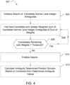
- a tree search of the candidate narrow lane integer ambiguities k,m ⁇ N NL may be initialized, such as by computing a Z-transform, for example.
- the nodes in the search tree are integer vectors.
- the next candidate narrow lane integer ambiguity k,m ⁇ N NL may be visited in the tree and weighted sums ⁇ z ⁇ w(z) of the candidate narrow lane integer ambiguities k,m ⁇ N NL and a sum of weights ⁇ w(z) may be updated.
- the weighting at step 506 may be adaptively scaled so that a large dynamic range in weight magnitudes of the candidates is avoided.
- ⁇ 0 2 may be dynamically changed during the search to be the minimum ⁇ 0 2 of all the candidates that have been visited during the search at that point. For each candidate visited during the search, partial sums of the numerator and denominator terms of equation (29) can therefore be accumulated.
- z 1 represents the best solution (i.e., where ⁇ 1 2 is a minimum) found so far in a search with w ( z 1 ) as its corresponding weight
- z c is an integer vector candidate at a current node of the search with a corresponding weight w ( z c )
- the candidate z c can be considered not significant when w ( z c ) « w ( z 1 ).
- Candidates may be included during the search as long as: w z c ⁇ ⁇ w z 1 , where ⁇ is a small threshold, such as 10 -6 . This is equivalent to: ⁇ c 2 ⁇ ⁇ 1 2 + ln 1 ⁇ 2 .
- determined ambiguity values k,m ⁇ can be formed based on the weighted sums of the candidate narrow lane integer ambiguities and the sum of weights. It can also be determined at step 508 whether there are candidates remaining with weights greater than a predetermined threshold. If there are still candidates remaining at step 508, then the process 307 may return to step 506 to continue the search and repeat step 506 on the next candidate. If there are no candidates remaining at step 508, then the process 307 may continue to step 510 to finalize the search, such as by applying a reverse Z-transform, for example.
- the determined ambiguity values k,m ⁇ may be utilized to form a constraint that can be applied to the float solution in order to calculate an ambiguity determined position solution ( ⁇ X BIE , ⁇ P BIE ) at step 512.
- a float change vector ⁇ N may be calculated as the difference of the determined ambiguity values k,m ⁇ (calculated at step 510) and the float ambiguity values k,m ⁇ . Accordingly, the float change vector ⁇ N may have elements consisting of k,m ⁇ - k,m ⁇ .
- a design matrix H may be formed. The design matrix H may have the same row dimensions as the float change vector ⁇ N and a column dimension equal to the state size of the float state vector X. Accordingly, each row of the design matrix H may have a +1 coefficient at the state index of and a -1 coefficient at the state index of , where m is the reference satellite for k.
- Correction terms may be formed at steps 608 and 610.
- a state correction term ⁇ X BIE K ⁇ N
- a covariance correction term ⁇ P BIE KHP.
- the state correction term ⁇ X BIE and the covariance correction term ⁇ P BIE may form the ambiguity determined position solution.
- the state vector can be corrected by adding the state correction term ⁇ X BIE (i.e., X + ⁇ X BIE ), and the covariance matrix can be corrected by subtracting the covariance correction term ⁇ P BIE (i.e., P - ⁇ P BIE ) .
- the determined ambiguity values k,m ⁇ may be time-smoothed at block 308 to generate smoothed ambiguity values k,m ⁇ .
- the steps performed in block 308 are shown in the process 308 of FIG. 6 .
- a smoothed BIE estimator may be updated with the determined ambiguity values k,m ⁇ to generate the smoothed ambiguity values k,m ⁇ .
- the smoothed ambiguity values k,m ⁇ are generally smoothly varying in time, changing gradually from the estimated float narrow lane ambiguities k,m ⁇ to the determined ambiguity values k,m ⁇ .
- the steps performed at step 702 are shown in the process 702 of FIG. 7 .
- the following terms and notation are used in the discussed on the process 702.
- k ⁇ represents the narrow lane float bias value for a satellite k in cycles;
- W represents the window length for smoothing determined narrow lane values and is given as an integer number of intervals (e.g., epochs);
- k C represents a smoothing count for satellite k, is given as an integer number of intervals (e.g., epochs), is initialized to 0, and is incremented by one each interval.
- t may denote the current interval and t - 1 may denote the previous interval.
- unavailable satellites may be removed from being used in the time-domain smoothing.
- An unavailable satellite may include satellites that the receiver can no longer receive signals from.
- it may be determined whether the reference satellite has changed from a previous interval. If the reference satellite has changed at step 804, then the process 702 continues to step 814 to calculate time-domain smoothed ambiguity values for the new reference satellite and satellites other than the removed unavailable satellites.
- the old reference satellite may be denoted as m 0 and the new reference satellite may be denoted as m 1 .
- step 806 it may be determined whether new satellites should be used in the time-domain smoothing. New satellites may include the satellites which were not used in utilized in a previous interval. If it is determined that no new satellites should be used at step 806, then the process 702 continues to step 812, as described below. However, if it is determined that new satellites should be used at step 806, then the process 702 continues to step 808.
- the time-domain smoothed ambiguity values for the new satellites may be adjusted at step 810 by a bias between the estimated float narrow lane ambiguities k,m ⁇ and time-domain smoothed ambiguity values k,m ⁇ from a previous interval.
- the initial bias may be minimized between the estimated float narrow lane ambiguities k,m ⁇ N NL and time-domain smoothed ambiguity values k,m ⁇ from the previous interval.
- N NL , SBIE k t ⁇ 1 N NL , SBIE k t ⁇ 1 + ⁇ k , m 1 ⁇ N NL , BIAS t ⁇ 1 ,
- k ⁇ ( t ) in equation (58) represents the respective undifferenced float ambiguity entries in the state vector increment ⁇ X SBIE of the ambiguity determined position solution from the prior interval.
- the time-domain smoothed ambiguity values for all of the satellites may be updated based on the determined ambiguity values k,m ⁇ .
- Step 812 may be performed following step 810 or if no new satellites were determined to be needed at step 806.
- an exponential filter such as a recursive estimator may be utilized but in other embodiments, other techniques for smoothing may be utilized.
- an ambiguity determined position solution ( ⁇ X SBIE , ⁇ P SBIE ) may be calculated at step 704 based on the smoothed ambiguity values k,m ⁇ .
- Step 704 may include the steps described above with relation to the process 600 of FIG. 5 , and may also correspond to block 309 of FIG. 2 .
- One difference is at step 606 where the Kalman gain K is computed.
- float ambiguity biases may be stored that are derived from the ambiguity determined position solution ( ⁇ X SBIE , ⁇ P SBIE ) from step 704. The float ambiguity biases are used as described above with relation to step 810 of the process 702 of FIG. 7 .
- a final position solution may be computed using block 350.
- Block 350 may include several steps, as shown in the process 350 of FIG. 8 .
- the weighting process described below may also be applied to the ambiguity determined position solution ( ⁇ X BIE , ⁇ P BIE ) from block 307, in some embodiments.
- the ambiguity determined position solution ( ⁇ X SBIE , ⁇ P SBIE ) from block 309 may be blended with the float solution from block 304 to form a weighted smoothed ambiguity determined position solution ( ⁇ X WSBIE , ⁇ P WSBIE ) .
- a time-weighted weighting factor w may be determined, where 0 ⁇ w ⁇ 1.
- the weighting may be determined based on one or more factors.
- the factors may include a minimum variance solution, an acceptability factor a that indicates whether the ambiguity determined position solution ( ⁇ X SBIE , ⁇ P SBIE ) is acceptable, a convergence indicator of the float solution, and/or a look-up table that is indexed by ranges of corresponding error variances and corresponding figures of merit of the float solution and the ambiguity determined position solution ( ⁇ X SBIE , ⁇ P SBIE ).
- the minimum variance solution factor may minimize an error variance g of a combination of the float solution and the ambiguity determined position solution ( ⁇ X SBIE , ⁇ P SBIE ).
- the error variances may be three dimensional position variances that are computed as a trace of the corresponding three dimensional position covariance matrix.
- the error variance of the float solution may be denoted as ⁇ FLOAT 2 and the error variance of the ambiguity determined position solution ( ⁇ X SBIE , ⁇ P SBIE ) may be denoted as ⁇ SBIE 2 .
- the error variance g will be limited according to 0 ⁇ g ⁇ 1, and will have a small value when the uncertainty of the ambiguity determined position solution ( ⁇ X SBIE , ⁇ P SBIE ) is large, and conversely will have a large value when the uncertainty of the float solution is relatively large.
- a time-filtered version g of the error variance g may be utilized due to noise.
- the acceptability factor a may indicate whether the ambiguity determined position solution ( ⁇ X SBIE , ⁇ P SBIE ) is acceptable and be limited according to 0 ⁇ a ⁇ 1.
- the acceptability factor a may be smaller when the ambiguity determined position solution ( ⁇ X SBIE , ⁇ P SBIE ) is unacceptable and may be larger when it is acceptable.
- the acceptability factor a may be dependent on a quality of the ambiguity determined position solution ( ⁇ X SBIE , ⁇ P SBIE ), such as based on the magnitude of the quadratic form of the ambiguity determined position solution ( ⁇ X SBIE , ⁇ P SBIE ) and the ratio test.
- the ratio test can be defined as the ratio of the quadratic form of the second best solution to the best solution. When the ratio is large, it can indicate that the best solution is the correct solution.
- the quadratic form of the ambiguity determined position solution ( ⁇ X SBIE , ⁇ P SBIE ) may be very large if there are problems with determining ambiguity values.
- the acceptability factor a may be 0.
- the ambiguity determined position solution ( ⁇ X SBIE , ⁇ P SBIE ) may be deemed more reliable and have an acceptability factor a of 1.
- the acceptability factor a may by found by a smooth function which decreases from 1 to 0 as the ratio decreases and the quadratic form increases.
- the convergence indicator factor may indicate whether the float solution has reached a steady state. In this case, the convergence indicator may be greater when the float solution has reached a steady state or is close to a steady state, and conversely may be less in other situations.
- the weighting factor w may be chosen based on a combination of these factors. For example, if the acceptability factor a ⁇ 1 or the float solution has converged and the ambiguity determined position solution ( ⁇ X SBIE , ⁇ P SBIE ) is determined to be not trustworthy, then the weighting factor w may be equal to a g . In other cases, the weighting factor w may be equal to the acceptability factor a .
- step 904 it may be determined at step 904 if the weighted smoothed ambiguity determined position solution ( ⁇ X WSBIE , ⁇ P WSBIE ) has a poor quality. If the weighted smoothed ambiguity determined position solution ( ⁇ X WSBIE , ⁇ P WSBIE ) has a poor quality, then the process 350 may continue to step 912 to transition to the float solution. However, if the weighted smoothed ambiguity determined position solution ( ⁇ X WSBIE , ⁇ P WSBIE ) does not have a poor quality then the process 350 may continue to step 906 (also embodied by block 311).
- an estimated position jump in the weighted smoothed ambiguity determined position solution ( ⁇ X WSBIE , ⁇ P WSBIE ) may be calculated.
- the estimated position jump may be calculated by comparing the change in position since the last interval to the change according to an estimate using the integrated carrier phase that infers positions between the intervals using carrier phase time differences, as is known in the art.
- it may be determined whether the estimated position jump from step 906 is greater than a predetermined threshold. If the estimated position jump is greater than the threshold, then the process 350 may continue to step 912 to transition to the float solution. However, if the estimated position jump is not greater than the threshold, then the process 350 may continue to step 910.
- the navigation output showing the position of the receiver may be updated at block 312 by adjusting the float solution from block 304 with the weighted smoothed ambiguity determined position solution ( ⁇ X WSBIE , ⁇ P WSBIE ).
- the state vector can be corrected by adding the state correction term ⁇ X WSBIE (i.e., X + ⁇ X WSBIE ), and the covariance matrix can be corrected by subtracting the covariance correction term ⁇ P WSBIE (i.e., P - ⁇ P WSBIE ).
- Transitioning to the float solution at step 912 may be performed to ensure that the transition is relatively smooth and not too rapid.
- an offset ⁇ X WSBIE is typically stored.
- the position change may be limited at each interval due to the offset ⁇ X t . In particular, the position change may be limited to not vary by more than a magnitude ⁇ that is a small predetermined value.
Landscapes
- Engineering & Computer Science (AREA)
- Radar, Positioning & Navigation (AREA)
- Remote Sensing (AREA)
- Computer Networks & Wireless Communication (AREA)
- Physics & Mathematics (AREA)
- General Physics & Mathematics (AREA)
- Signal Processing (AREA)
- Position Fixing By Use Of Radio Waves (AREA)
- Navigation (AREA)
Applications Claiming Priority (4)
| Application Number | Priority Date | Filing Date | Title |
|---|---|---|---|
| US201662310297P | 2016-03-18 | 2016-03-18 | |
| US15/281,012 US10222483B2 (en) | 2016-03-18 | 2016-09-29 | Satellite navigation receiver with improved ambiguity resolution |
| EP17767183.1A EP3430430B1 (fr) | 2016-03-18 | 2017-03-09 | Récepteur de navigation par satellite à résolution d'ambiguïté améliorée |
| PCT/US2017/021548 WO2017160583A1 (fr) | 2016-03-18 | 2017-03-09 | Récepteur de navigation par satellite à résolution d'ambiguïté améliorée |
Related Parent Applications (1)
| Application Number | Title | Priority Date | Filing Date |
|---|---|---|---|
| EP17767183.1A Division EP3430430B1 (fr) | 2016-03-18 | 2017-03-09 | Récepteur de navigation par satellite à résolution d'ambiguïté améliorée |
Publications (2)
| Publication Number | Publication Date |
|---|---|
| EP4550002A2 true EP4550002A2 (fr) | 2025-05-07 |
| EP4550002A3 EP4550002A3 (fr) | 2025-07-23 |
Family
ID=59847493
Family Applications (6)
| Application Number | Title | Priority Date | Filing Date |
|---|---|---|---|
| EP22155201.1A Pending EP4012456A3 (fr) | 2016-03-18 | 2017-03-09 | Récepteur de navigation par satellite à résolution d'ambiguïté améliorée |
| EP17767183.1A Active EP3430430B1 (fr) | 2016-03-18 | 2017-03-09 | Récepteur de navigation par satellite à résolution d'ambiguïté améliorée |
| EP22155213.6A Withdrawn EP4030197A1 (fr) | 2016-03-18 | 2017-03-09 | Récepteur de navigation par satellite à résolution d'ambiguïté améliorée |
| EP24220814.8A Pending EP4550002A3 (fr) | 2016-03-18 | 2017-03-09 | Recepteur de navigation par satellite a resolution d'ambigutteamelioree |
| EP22155209.4A Pending EP4030196A1 (fr) | 2016-03-18 | 2017-03-09 | Récepteur de navigation par satellite à résolution d'ambiguïté améliorée |
| EP17767185.6A Active EP3430429B1 (fr) | 2016-03-18 | 2017-03-09 | Récepteur de navigation par satellite à résolution d'ambiguïté améliorée |
Family Applications Before (3)
| Application Number | Title | Priority Date | Filing Date |
|---|---|---|---|
| EP22155201.1A Pending EP4012456A3 (fr) | 2016-03-18 | 2017-03-09 | Récepteur de navigation par satellite à résolution d'ambiguïté améliorée |
| EP17767183.1A Active EP3430430B1 (fr) | 2016-03-18 | 2017-03-09 | Récepteur de navigation par satellite à résolution d'ambiguïté améliorée |
| EP22155213.6A Withdrawn EP4030197A1 (fr) | 2016-03-18 | 2017-03-09 | Récepteur de navigation par satellite à résolution d'ambiguïté améliorée |
Family Applications After (2)
| Application Number | Title | Priority Date | Filing Date |
|---|---|---|---|
| EP22155209.4A Pending EP4030196A1 (fr) | 2016-03-18 | 2017-03-09 | Récepteur de navigation par satellite à résolution d'ambiguïté améliorée |
| EP17767185.6A Active EP3430429B1 (fr) | 2016-03-18 | 2017-03-09 | Récepteur de navigation par satellite à résolution d'ambiguïté améliorée |
Country Status (4)
| Country | Link |
|---|---|
| US (2) | US10379225B2 (fr) |
| EP (6) | EP4012456A3 (fr) |
| CN (3) | CN117055078A (fr) |
| WO (2) | WO2017160586A1 (fr) |
Families Citing this family (22)
| Publication number | Priority date | Publication date | Assignee | Title |
|---|---|---|---|---|
| US10274606B1 (en) * | 2016-03-09 | 2019-04-30 | Rockwell Collins, Inc. | High integrity partial almost fix solution |
| US10379225B2 (en) | 2016-03-18 | 2019-08-13 | Deere & Company | Satellite navigation receiver with improved ambiguity resolution |
| US10222484B2 (en) | 2016-03-18 | 2019-03-05 | Deere & Company | Satellite navigation receiver with improved ambiguity resolution |
| EP3462213B1 (fr) * | 2017-09-28 | 2026-04-29 | ANavS GmbH | Procédé de positionnement de point précis dans un système de navigation par satellite |
| CN108037521A (zh) * | 2018-01-29 | 2018-05-15 | 东南大学 | 一种基于北斗超宽巷约束的bds/gps宽巷模糊度单历元固定方法 |
| US11221417B2 (en) | 2018-12-27 | 2022-01-11 | Samsung Electronics Co., Ltd. | Recovery of high precision position after GNSS outage |
| CN110196442B (zh) * | 2019-06-13 | 2021-04-13 | Oppo广东移动通信有限公司 | 搜星方法、装置、存储介质及移动终端 |
| CN112363186B (zh) * | 2019-12-27 | 2023-06-02 | 广东电网有限责任公司电力科学研究院 | 一种卫星天线相位中心参数的计算方法和装置 |
| US12016257B2 (en) | 2020-02-19 | 2024-06-25 | Sabanto, Inc. | Methods for detecting and clearing debris from planter gauge wheels, closing wheels and seed tubes |
| CN111638535B (zh) * | 2020-05-15 | 2022-02-25 | 山东科技大学 | 一种用于gnss实时精密单点定位的混合模糊度固定方法 |
| US12461083B2 (en) | 2020-08-03 | 2025-11-04 | Sabanto, Inc. | Methods for improved agricultural procedures |
| US11592580B2 (en) * | 2020-08-20 | 2023-02-28 | Qualcomm Incorporated | Multi-frequency real-time kinematic (RTK) measurements for global navigation satellite system (GNSS) receivers |
| CN115032666B (zh) * | 2021-03-03 | 2025-03-14 | 千寻位置网络有限公司 | 一种浮点模糊度固定方法、轨道解算方法及钟差解算方法 |
| CN114624753B (zh) * | 2022-02-24 | 2023-04-07 | 广州南方卫星导航仪器有限公司 | 利用bds3-ppp服务与短报文实现ppp-ar的方法及系统 |
| US12032077B2 (en) | 2022-03-11 | 2024-07-09 | Deere & Company | System and method for compensating for scintillation and for facilitation of long-baseline RTK |
| CN116520379B (zh) * | 2023-04-19 | 2025-07-15 | 厦门新诺电子有限公司 | 基线解算中浮点解的求解方法、装置及存储介质 |
| CN116660958B (zh) * | 2023-07-31 | 2023-10-20 | 武汉大学 | 整周模糊度并行滤波解算方法、装置、设备及存储介质 |
| CN117492043B (zh) * | 2023-12-29 | 2024-05-03 | 天津云遥宇航科技有限公司 | 一种基于shapiro时延和周期性相对论效应改正方法 |
| CN118566961B (zh) * | 2024-07-31 | 2024-11-29 | 长沙金维集成电路股份有限公司 | 一种卫星导航系统的导航值的解算方法及装置 |
| CN119199928B (zh) * | 2024-09-09 | 2025-04-01 | 浙江工业大学 | 一种基于整数约束型高斯滤波的rtk定位方法 |
| CN120276249A (zh) * | 2025-03-26 | 2025-07-08 | 中国人民解放军军事航天部队航天工程大学 | 挠性航天器t-s模糊姿轨一体化建模与自适应滑模控制方法 |
| CN119986741A (zh) * | 2025-04-15 | 2025-05-13 | 中国地震局第二监测中心 | 基于北斗卫星的单点定位方法及装置、设备、存储介质 |
Family Cites Families (50)
| Publication number | Priority date | Publication date | Assignee | Title |
|---|---|---|---|---|
| US5519620A (en) | 1994-02-18 | 1996-05-21 | Trimble Navigation Limited | Centimeter accurate global positioning system receiver for on-the-fly real-time kinematic measurement and control |
| US5610614A (en) | 1995-09-13 | 1997-03-11 | Trimble Navigation Limited | Real-time kinematic initialization test system |
| US6057800A (en) * | 1996-06-28 | 2000-05-02 | State University Of New York | RDOP surface for GPS relative positioning |
| US6127968A (en) * | 1998-01-28 | 2000-10-03 | Trimble Navigation Limited | On-the-fly RTK positioning system with single frequency receiver |
| US8212719B2 (en) * | 2001-06-06 | 2012-07-03 | Global Locate, Inc. | Method and apparatus for background decoding of a satellite navigation message to maintain integrity of long term orbit information in a remote receiver |
| US20080125971A1 (en) * | 2001-06-06 | 2008-05-29 | Van Diggelen Frank | Method and apparatus for improving accuracy and/or integrity of long-term-orbit information for a global-navigation-satellite system |
| US20080186229A1 (en) * | 2001-06-06 | 2008-08-07 | Van Diggelen Frank | Method and Apparatus for Monitoring Satellite-Constellation Configuration To Maintain Integrity of Long-Term-Orbit Information In A Remote Receiver |
| JP4116792B2 (ja) * | 2001-12-19 | 2008-07-09 | 古野電気株式会社 | キャリア位相相対測位装置 |
| US6664923B1 (en) * | 2002-09-24 | 2003-12-16 | Novatel, Inc. | Position and velocity Kalman filter for use with global navigation satelite system receivers |
| US7432853B2 (en) | 2003-10-28 | 2008-10-07 | Trimble Navigation Limited | Ambiguity estimation of GNSS signals for three or more carriers |
| US7119741B2 (en) | 2004-01-13 | 2006-10-10 | Navcom Technology, Inc. | Method for combined use of a local RTK system and a regional, wide-area, or global carrier-phase positioning system |
| US7102563B2 (en) * | 2004-02-26 | 2006-09-05 | Topcon Gps Llc | Methods and apparatuses of estimating the position of a mobile user in a system of satellite differential navigation |
| US7071871B2 (en) * | 2004-03-25 | 2006-07-04 | Raytheon Company | Low power dissipation tracking architecture for GPS navigation systems |
| US20050212696A1 (en) * | 2004-03-25 | 2005-09-29 | Bartone Chris G | Reat-time WaveSmooth™ error mitigation for Global Navigation Satellite Systems |
| US20050216210A1 (en) * | 2004-03-25 | 2005-09-29 | Bartone Chris G | Real-time code multipath mitigation in the frequency domain using FDsmooth™ for Global Navigation Satellite Systems |
| US7298319B2 (en) | 2004-04-19 | 2007-11-20 | Magellan Navigation, Inc. | Automatic decorrelation and parameter tuning real-time kinematic method and apparatus |
| CA2570861C (fr) | 2004-06-16 | 2014-08-05 | E-Radio Usa, Inc. | Systemes et procedes de positionnement geographique au moyen de signatures spectrales radio |
| US7868820B2 (en) * | 2005-09-09 | 2011-01-11 | Trimble Navigation Limited | Ionosphere modeling apparatus and methods |
| US7739032B2 (en) * | 2006-03-21 | 2010-06-15 | Broadcom Corporation | Method and apparatus for generating and using a regional-terrain model |
| US7982667B2 (en) * | 2006-04-17 | 2011-07-19 | Trimble Navigation Limited | Post-processed accuracy prediction for GNSS positioning |
| US20080077325A1 (en) * | 2006-09-25 | 2008-03-27 | Honeywell International Inc. | Systems and methods for a hybrid transition matrix |
| US7961143B2 (en) | 2007-05-31 | 2011-06-14 | Navcom Technology, Inc. | Partial search carrier-phase integer ambiguity resolution |
| US9651667B2 (en) * | 2007-06-22 | 2017-05-16 | Trimble Inc. | Combined cycle slip indicators for regionally augmented GNSS |
| WO2009000314A1 (fr) | 2007-06-22 | 2008-12-31 | Trimble Terrasat Gmbh | Dispositif et procédé de détection de position |
| US7868819B2 (en) | 2007-09-07 | 2011-01-11 | The Board Of Trustees Of The Leland Stanford Junior University | Arrangements for satellite-based navigation and methods therefor |
| EP2040090A1 (fr) * | 2007-09-18 | 2009-03-25 | Leica Geosystems AG | Procédé d'estimation de précision d'un réseau selon les corrections pour système de positionnement assisté par satellite |
| WO2009058213A2 (fr) | 2007-10-30 | 2009-05-07 | Trimble Navigation Limited | Fixation partielle généralisée |
| WO2012128980A1 (fr) * | 2011-03-22 | 2012-09-27 | Trimble Navigation Limited | Traitement de signaux gnss avec position connue pour reconvergence |
| ES2413064T3 (es) * | 2008-04-22 | 2013-07-15 | Deutsches Zentrum für Luft- und Raumfahrt e.V. | Procedimiento para un sistema de navegación global por satélite |
| WO2010021658A2 (fr) | 2008-08-19 | 2010-02-25 | Trimble Navigation Limited | Procédés de traitement de signaux de système de navigation par satellites et appareil d’interruption de poursuite |
| CN102171583B (zh) * | 2008-10-06 | 2015-02-18 | 天宝导航有限公司 | 位置估计方法和设备 |
| DE112010003699B4 (de) | 2009-09-19 | 2024-10-02 | Trimble Inc. (n.d.Ges.d.Staates Delaware) | GNSS-Signalverarbeitung zum Schätzen von phasen-angepassten Zeitsignalen |
| ES2426865T3 (es) * | 2009-10-08 | 2013-10-25 | Deutsches Zentrum für Luft- und Raumfahrt e.V. | Resolución parcial de la ambigüedad para la estimación del retardo ionosférico multifrecuencia |
| EP2333581A1 (fr) * | 2009-12-09 | 2011-06-15 | Technische Universität München | Évaluation de biais de phase et de code sur plusieurs fréquences avec un filtre Kalman |
| CN102834732B (zh) * | 2010-02-14 | 2014-11-26 | 天宝导航有限公司 | 使用区域增强网络的gnss信号处理 |
| US8659474B2 (en) * | 2011-01-12 | 2014-02-25 | Navcom Technology, Inc. | Navigation system and method for resolving integer ambiguities using double difference ambiguity constraints |
| CN103502843B (zh) | 2011-03-22 | 2015-05-20 | 天宝导航有限公司 | 具有三角相的gnss信号处理 |
| US8872700B2 (en) * | 2011-04-06 | 2014-10-28 | Javad Gnss, Inc. | GNSS surveying receiver with multiple RTK engines |
| US8599067B2 (en) * | 2011-07-26 | 2013-12-03 | Cambridge Silicon Radio Ltd. | Mitigating multipath using state transition detection and measurement |
| CN102353969B (zh) * | 2011-09-02 | 2013-07-31 | 东南大学 | 精密单点定位技术中相位偏差的估计方法 |
| GB201204006D0 (en) | 2012-03-07 | 2012-04-18 | Tomtom Int Bv | Point of interest database maintenance system |
| EP2759849B1 (fr) | 2013-01-28 | 2018-01-17 | Technische Universität München | Procédé, réseau de stations de référence et dispositif mobile de navigation pour la détermination d'au moins un paramètre réel, en particulier la position d'un récepteur par un système de navigation par satellite |
| US20150369924A1 (en) * | 2013-02-04 | 2015-12-24 | Vanderbilt University | Method and system for high-accuracy differential tracking of global positioning system (gps) receivers |
| US9057780B2 (en) | 2013-04-18 | 2015-06-16 | California Institute Of Technology | Real-time and post-processed orbit determination and positioning |
| EP3110695B1 (fr) * | 2014-02-26 | 2023-11-08 | PNT Holdings, Inc. | Architecture de système mondial de navigation par satellite présentant une performance et un coût améliorés |
| NL2013473B1 (en) * | 2014-09-15 | 2016-09-28 | Fugro N V | Precise GNSS positioning system with improved ambiguity estimation. |
| CN105372691B (zh) * | 2015-08-18 | 2017-08-11 | 中国人民解放军国防科学技术大学 | 一种模糊度固定的长基线卫星编队gnss相对定位方法 |
| CN105353393B (zh) * | 2015-10-22 | 2017-10-20 | 北京理工大学 | 一种双频载波相位整周模糊度固定的方法 |
| US10379225B2 (en) | 2016-03-18 | 2019-08-13 | Deere & Company | Satellite navigation receiver with improved ambiguity resolution |
| US10222484B2 (en) | 2016-03-18 | 2019-03-05 | Deere & Company | Satellite navigation receiver with improved ambiguity resolution |
-
2016
- 2016-09-29 US US15/281,016 patent/US10379225B2/en active Active
- 2016-09-29 US US15/281,012 patent/US10222483B2/en active Active
-
2017
- 2017-03-09 EP EP22155201.1A patent/EP4012456A3/fr active Pending
- 2017-03-09 CN CN202311027493.3A patent/CN117055078A/zh active Pending
- 2017-03-09 CN CN201780018355.5A patent/CN109196380B/zh active Active
- 2017-03-09 WO PCT/US2017/021561 patent/WO2017160586A1/fr not_active Ceased
- 2017-03-09 EP EP17767183.1A patent/EP3430430B1/fr active Active
- 2017-03-09 EP EP22155213.6A patent/EP4030197A1/fr not_active Withdrawn
- 2017-03-09 WO PCT/US2017/021548 patent/WO2017160583A1/fr not_active Ceased
- 2017-03-09 EP EP24220814.8A patent/EP4550002A3/fr active Pending
- 2017-03-09 CN CN201780018377.1A patent/CN109196379B/zh active Active
- 2017-03-09 EP EP22155209.4A patent/EP4030196A1/fr active Pending
- 2017-03-09 EP EP17767185.6A patent/EP3430429B1/fr active Active
Also Published As
| Publication number | Publication date |
|---|---|
| CN109196380B (zh) | 2023-06-02 |
| WO2017160586A1 (fr) | 2017-09-21 |
| EP3430430B1 (fr) | 2024-12-18 |
| CN117055078A (zh) | 2023-11-14 |
| EP3430429B1 (fr) | 2022-03-30 |
| CN109196379A (zh) | 2019-01-11 |
| EP3430430A4 (fr) | 2020-03-18 |
| EP4030196A1 (fr) | 2022-07-20 |
| EP3430429A4 (fr) | 2020-03-18 |
| EP4012456A3 (fr) | 2022-10-12 |
| US10379225B2 (en) | 2019-08-13 |
| EP3430430A1 (fr) | 2019-01-23 |
| EP4030197A1 (fr) | 2022-07-20 |
| US20170269230A1 (en) | 2017-09-21 |
| CN109196380A (zh) | 2019-01-11 |
| US10222483B2 (en) | 2019-03-05 |
| CN109196379B (zh) | 2023-08-04 |
| EP3430429A1 (fr) | 2019-01-23 |
| EP4012456A2 (fr) | 2022-06-15 |
| WO2017160583A1 (fr) | 2017-09-21 |
| BR112018068546A2 (pt) | 2019-02-12 |
| US20170269228A1 (en) | 2017-09-21 |
| EP4550002A3 (fr) | 2025-07-23 |
| BR112018068679A2 (pt) | 2019-01-15 |
Similar Documents
| Publication | Publication Date | Title |
|---|---|---|
| EP3430429B1 (fr) | Récepteur de navigation par satellite à résolution d'ambiguïté améliorée | |
| US10222484B2 (en) | Satellite navigation receiver with improved ambiguity resolution | |
| US11002860B2 (en) | GNSS-RTK-based positioning method | |
| RU2591953C2 (ru) | Навигационная система и способ разрешения целочисленных неоднозначностей с использованием ограничения неоднозначности двойной разности | |
| EP3430438B1 (fr) | Estimation de biais inter-fréquence pour résolution d'ambiguïté dans des récepteurs de système global de navigation par satellite | |
| CN102124371B (zh) | 具有模糊度收敛性指示的gnss信号处理方法和装置 | |
| CN116299586A (zh) | 基于广播星历的精密单点定位方法、接收机、设备和介质 | |
| BR112018068710B1 (pt) | Método de posicionamento de ponto preciso para determinar uma posição de um receptor de navegação de satélite, e, receptor de navegação por satélite | |
| BR112018068679B1 (pt) | Método para determinar uma posição de um receptor de navegação de satélite, e, receptor de navegação de satélite | |
| BR112018068546B1 (pt) | Métodos para uniformizar valores de ambiguidade, para formar uma restrição, para transição de uma solução de posição e para determinar uma posição de um receptor de navegação de satélite | |
| CN114675313A (zh) | 修正rtk移动站差分方程的浮点解坐标的解算方法 | |
| Alam et al. | Modified precise point positioning with ambiguity validation for better performance |
Legal Events
| Date | Code | Title | Description |
|---|---|---|---|
| PUAI | Public reference made under article 153(3) epc to a published international application that has entered the european phase |
Free format text: ORIGINAL CODE: 0009012 |
|
| STAA | Information on the status of an ep patent application or granted ep patent |
Free format text: STATUS: THE APPLICATION HAS BEEN PUBLISHED |
|
| AC | Divisional application: reference to earlier application |
Ref document number: 3430430 Country of ref document: EP Kind code of ref document: P |
|
| AK | Designated contracting states |
Kind code of ref document: A2 Designated state(s): AL AT BE BG CH CY CZ DE DK EE ES FI FR GB GR HR HU IE IS IT LI LT LU LV MC MK MT NL NO PL PT RO RS SE SI SK SM TR |
|
| PUAL | Search report despatched |
Free format text: ORIGINAL CODE: 0009013 |
|
| AK | Designated contracting states |
Kind code of ref document: A3 Designated state(s): AL AT BE BG CH CY CZ DE DK EE ES FI FR GB GR HR HU IE IS IT LI LT LU LV MC MK MT NL NO PL PT RO RS SE SI SK SM TR |
|
| RIC1 | Information provided on ipc code assigned before grant |
Ipc: G01S 19/44 20100101AFI20250617BHEP |
|
| STAA | Information on the status of an ep patent application or granted ep patent |
Free format text: STATUS: REQUEST FOR EXAMINATION WAS MADE |
|
| 17P | Request for examination filed |
Effective date: 20260120 |