EP4549886A2 - Ultraschalldurchflussmesser und verfahren zur bestimmung einer durchflussrate - Google Patents
Ultraschalldurchflussmesser und verfahren zur bestimmung einer durchflussrate Download PDFInfo
- Publication number
- EP4549886A2 EP4549886A2 EP25152742.0A EP25152742A EP4549886A2 EP 4549886 A2 EP4549886 A2 EP 4549886A2 EP 25152742 A EP25152742 A EP 25152742A EP 4549886 A2 EP4549886 A2 EP 4549886A2
- Authority
- EP
- European Patent Office
- Prior art keywords
- parameter
- ultrasonic
- transmitter
- sampling
- time
- Prior art date
- Legal status (The legal status is an assumption and is not a legal conclusion. Google has not performed a legal analysis and makes no representation as to the accuracy of the status listed.)
- Pending
Links
Images




Classifications
-
- G—PHYSICS
- G01—MEASURING; TESTING
- G01F—MEASURING VOLUME, VOLUME FLOW, MASS FLOW OR LIQUID LEVEL; METERING BY VOLUME
- G01F1/00—Measuring the volume flow or mass flow of fluid or fluent solid material wherein the fluid passes through a meter in a continuous flow
- G01F1/66—Measuring the volume flow or mass flow of fluid or fluent solid material wherein the fluid passes through a meter in a continuous flow by measuring frequency, phase shift or propagation time of electromagnetic or other waves, e.g. using ultrasonic flowmeters
-
- G—PHYSICS
- G01—MEASURING; TESTING
- G01F—MEASURING VOLUME, VOLUME FLOW, MASS FLOW OR LIQUID LEVEL; METERING BY VOLUME
- G01F1/00—Measuring the volume flow or mass flow of fluid or fluent solid material wherein the fluid passes through a meter in a continuous flow
- G01F1/66—Measuring the volume flow or mass flow of fluid or fluent solid material wherein the fluid passes through a meter in a continuous flow by measuring frequency, phase shift or propagation time of electromagnetic or other waves, e.g. using ultrasonic flowmeters
- G01F1/667—Arrangements of transducers for ultrasonic flowmeters; Circuits for operating ultrasonic flowmeters
Definitions
- the present invention relates to an ultrasonic flow meter and a method of determining a flow rate of a fluid in a flow path between two transducers: a transmitter Tx and a receiver R x .
- the method comprises acts that will be described. There is an act of transmitting multiple wave packets each generated with a set of Tx-parameters through the flow path. At least two wave packets have different Tx-parameter values. There is an act of receiving the multiple wave packets.
- the invention also includes means for performing the acts as well as computer programs with instructions to perform the acts.
- Flow metering in different variations are known. There are ultrasonic flow meters for determining flow rate of a consumed medium such as a fluid in a flow path.
- the ultrasonic waves may be generated by piezo-electric transducers and the waves may be transient in the sense of being limited to time periods. Such transient waves are generally known as wave packets.
- WO 2012/055413 discloses an ultrasonic flow meter with zero impedance measuring electronics to improve determination of flow rate.
- EP 2581715A1 discloses an ultrasonic flow meter adapted to estimate and to correct phase errors in received ultrasonic signals.
- WO 2011/134470 A2 discloses ultrasonic flow meter principles based on comparing physically transmitted, delayed and received signals with simulated non-delayed signals.
- WO 2018/006912 A1 attempts to improve ultrasonic flow meter of the transit-time based type and discusses aspects of measuring the fluid convoluted signals.
- An object of the invention is achieved by a method of determining a flow rate of a fluid in a flow path.
- the method is performed by a transmitter Tx and a receiver R x .
- the method comprises acts that will be described.
- each wave packet generated with, i.e. from, a set of Tx-parameter types. At least two wave packets have different Tx-parameter values.
- the ultrasonic wave packets are thus formed and shaped by selecting transmit-parameter types (Tx parameters types) from a group or set of parameter types, which types are particularly useful for increasing the resolution and amount of data received when sampling the received wave packets.
- the received wave packets are the electronic representations of the transmitted wave packets having travelled through the fluid in the flow path.
- the flow rate determination is thus based upon the received wave packets which are electronically sampled.
- the electronic samples represented as a data series are read and processed by a digital controller which calculates the flow rate.
- the at least two ultrasonic wave packets are not transmitted simultaneously, i.e. transmitter Tx and receiver Rx are sending sequentially. Transmitting the multiple wave packets at the same time is possible but would require high performance receiving electronics i.e. expensive receiver Rx unit or sampling arrangement. This is opposite to the goal targeted by the current invention.
- an electronic excitation waveform is impacted or shaped by applying one or more parameters from the group of Tx-parameter types to the electronic excitation waveform.
- the waveform is hereby biased and then sent via the transmitter as an ultrasonic signal through the fluid to the receiver.
- a further advantage is that the electronic receiver R x unit or sampling arrangement may be configured with greater flexibility than otherwise or with fewer restrictions to match the transmitter settings or configuration.
- the error level is reduced. In particular systematic errors are reduced, suppressed or eliminated. This also applies to the noise level of the flow measurement.
- the method offers the further advantage of reducing the noise of the flow measurement.
- the noise in question is recurring in the same shape with each measurement, it can be efficiently suppressed by varying appropriate Tx-parameters.
- An example of such recurring noise is a parasitic oscillation of one or both ultrasonic transducers at the time of the measurement. This oscillation could be a residue from the inevitable transducer excitation taking place during power-up of the measurement circuit.
- noise suppression advantages do not only apply to measurement systems with digital sampling, but also to analogue systems and systems based on time-to-digital conversion.
- inventive method applies to analogue and/or digital systems.
- the method will reduce or eliminate systematic imperfections, which can be efficiently suppressed. Improved precision is achieved by varying one or more attributes of the excitation waveform applied to the transmitting ultrasonic transmitter or transducer.
- the frequency can be varied within the transducer bandwidth, typically in the order of a few 10s of kHz for a water loaded transducer, such as in the range of 1 kHz to 50 kHz.
- the ultrasonic wave packets can be transmitted upstream or downstream with respect to the fluid flow direction.
- the Tx and Rx transducers change role when the wave packet transmission direction is changed.
- the at least two transmitted ultrasonic wave packets are generated by using a Tx-parameter type where the types used are of different types.
- a first transmitted ultrasonic wave packet uses one Tx-parameter type and a second transmitted ultrasonic wave uses a type different from the first type.
- the at least two transmitted ultrasonic wave packets are in a first step sent in a co-propagating direction of the fluid and then in a following subsequent step sent in a counter-flow propagating direction of the fluid.
- the Tx-parameter type is a transmittal-offset-parameter in time and the offset is from a power up time, such as the time when the circuit is powered on, to the time of transmittal of a wave packet.
- the Tx-parameter type is a frequency-parameter.
- the Tx-parameter type is a phase-parameter.
- the inventive method contains an embodiment wherein a Tx-parameter of a first type is transmitted at least twice and with differing first type Tx-parameter values.
- a Tx-parameter of a second type is transmitted at least twice and with differing second type Tx-parameter values. This has the advantage of increasing the resolution of the sampled data even more.
- the Tx-parameter type is a polarity-parameter. This corresponds to a change of sign of the excitation waveform generated by the controller. This is useful to suppress noise in the received signals.
- the change of sign of the excitation waveform is advantageous when the noise to suppress is recurring in the same form for every ultrasonic signal acquired.
- a waveform phase of an excitation signal is changed in polarity while the waveform has a phase between 0 and 180 degrees.
- the act of determining the flow rate is performed as a function of different Tx-parameter types. This enables the possibility of efficiently suppressing noise, both of systematic and non-systematic character. Moreover, the digital resolution of the measurement is improved.
- one Tx-parameter is of one type, preferably a wave packet-transmittal-offset-parameter, and another Tx-parameter is of another type, advantageously a polarity-parameter.
- This combination results in improved digital accuracy as well as suppression of random as well as recurring noise and has proved in tests to be an advantageous combination of parameter types.
- the act of receiving a transmitted wave packet as a received wave packet is performed based on a set of R x -parameters, wherein the act of receiving includes an act of sampling the transmitted wave packet.
- the act of sampling is performed at or above the Nyquist-Shannon sampling rate; when gas-phase media are monitored the Nyquist-Shannon limit is typically in the range 20-1000 kS/s, whereas when liquid media are monitored the Nyquist-Shannon limit is typically in the 1000-10000 kS/s range.
- the act of sampling is performed at or below the Nyquist-Shannon sampling rate. This is a preferred embodiment.
- An object of the invention is achieved by an ultrasonic flow meter comprising transmitter (Tx) and receiver (R x ) ultrasonic units and means adapted to perform the acts as disclosed.
- a microcontroller output generates an electronic excitation waveform which waveform is shaped by one or more of the Tx-parameter types and Tx-parameter values, i.e. the electronic excitation waveform is formed and defined by applying one or more transmit parameters from the group or set of Tx-parameters to the electronic excitation waveform.
- After shaping the electronic excitation waveform it is transmitted as an ultrasonic wave packet through the fluid from the transmitter (Tx) to the receiver (Rx), then received as received wave packets which are sampled and converted to a series of sampled data representing the received wave packets.
- the transmitter Tx and the R x are piezoelectric transducers.
- transducers can be based on ceramics based on lead, zirconate and titanante (PZT) or similar, they can be monocrystals or electrostatic devices.
- PZT lead, zirconate and titanante
- the transmit parameter types are according to the invention preferably selected from a group of parameters containing at least the following 1) transmittal offset time (transmitter start time), 2) polarity, 3) signal frequency, 4) number of oscillations per time unit, 5) starting phase of the electronic excitation waveform and 6) frequency chirp.
- An object of the invention is achieved a by computer program product comprising instructions to cause the ultrasonic unit to execute the outlined acts of determining the fluid flow rate.
- An object of the invention is achieved by a computer-readable medium having stored there on the computer program as disclosed.
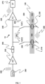
- FIGS. 1 to 6 illustrate embodiments of ultrasonic flow meter circuitry with a transmitter and a receiver in a flow path.
- the figures illustrate aspects which will be outlined in the following.
- the ultrasonic flow meter 10 comprises a transmitter Tx, 210 and a receiver R x , 220.
- the transmitter 210 and the receiver 220 may be a transducer 200.
- the parameters 400 of the Tx-waveforms which are converted to the ultrasonic wave packets 300 are varied by software in a micro controller and directed to an output pin 260. Subsequently, the Tx-waveforms are amplified by an amplifier 230 and directed to the selected transmitter 210 via an analogue switch SW0.
- This switch could be a simple mechanical relay or a semiconductor switch based on one or more field emitting transistors. The switches 250 are never closed simultaneously. After propagating along with the flowing fluid 100 the wave packet 300 is detected by the R x transmitter 220.
- the current generated by the transducer is converted into a voltage by a resistor and amplified by an amplifier 240 before the received wave package 320 enters the signal processing (SP) means 275, where information needed for the flow calculation is extracted.
- SP signal processing
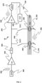
- the signal processing could be based on an analogue-to-digital converter (ADC) and a digital signal processor (DSP) as illustrated in Figure 2 . It could also be an analogue circuit or a time-to-digital converter.
- the received wave package 320 is sampled by the analogue-to-digital converter 270 and a sampled wave packet 330 is the outcome.
- the sampled wave packet 330 consists of a series of discrete measurement data where each data element of the series represents a voltage of the received data package 320 measured at a defined time instant.
- An example of a measurement data series is shown as a collection of dots in the graphic representation of the sampled wave packet 330 in Figure 2 . The dots are connected with lines in order to assist in reading the graphic.
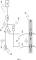
- FIG 3 , Figure 4 , Figure 5 and Figure 6 illustrate, using essentially the same elements and terms from figures 1 and 2 , examples of alternative analogue couplings which could be utilised to generate and receive the ultrasonic signals. These embodiments need not rely on digital sampling and DSP in order to provide a flow calculation. Analogue methods and/or time-to-digital conversion would also work and a person skilled in the art will appreciate the suggested outlines as starting points for practical realisation(s).
- Transmitter 210 is configured to produce a wave packet 300, which wave packet 300 travels through a fluid 100 in a flow path 120 and is received as a received wave packet 320, thereby enabling determination of the flow rate 120 as will be described in the following.
- a first step 1100 there is an act of transmitting multiple wave packets 300 both upstream and downstream.
- Each pair of up / downstream wave packets 300 is generated with a set of Tx-parameters 400 and is transmitted through the flow path 120.
- At least two wave packets 300 have different Tx-parameter values 410.
- a1 is a first frequency and a2 is a second and different frequency.
- the Tx parameters are of the same type (frequency) but having different values (e.g. 1,1 Mhz versus 1,0 MHz).
- FIG 7 there is also an act 1200 of receiving the multiple wave packet pairs 300.
- the wave packets, having traveled through the fluid 100 in the flow path 120 has been "convoluted” with information about the fluid condition.
- Figure 8 illustrates, also with exemplary reference primarily to Figure 1 although also applicable to Figures 2-6 , a method 1050 of determining a flow rate of a fluid 100 in a flow path with wave packets 300 with different Tx-parameter types 405A and 405B and values 410i and 410ii.
- Tx-parameter type 405A has different Tx values 410i, 410ii.
- Tx-parameter type 405A has different Tx values 410i, 410ii.
- inventive embodiments of Figures 1 to 6 and 7 ; and Figures 1 to 6 and 8 relate to ultrasonic flow meters 10 based on the so-called time-of-flight (TOF) principle and the embodiments have proven useful for legal metrology, where the consumption of a fluid needs to be recorded for later billing.
- TOF time-of-flight
- the fluid 100 could be potable water, hot water district heating water, district cooling water or gas.
- the flow meters 10 have low power consumption and/or high accuracy. Furthermore, they have a robustness against fouling. Finally, they are difficult to tamper with and they have no moving parts that can wear down over time.
- the time-of-flight measurement principle involves emitting ultrasonic signals into the flowing fluid 100 from one transmitter (Tx) 210 and measuring the time until it is picked up by a transducer (R x ) 220 placed at a different position relative to the transmitter (Tx).
- ultrasonic transducers 200 are usually resonant devices with resonance frequencies, ⁇ , in the range 0,5 - 5 MHz for liquids and 0,01 - 0,5 MHz for gaseous media.
- the ultrasonic signal i.e. the wave packet 300 of Figure 1
- the propagation times t up and t dn can be measured using a time-to-digital converter (TDC) initiated by the waveform sent to the emitting transmitter (Tx) 210.
- TDC time-to-digital converter
- the TDC is typically stopped by one or more identified traits of the transmitted ultrasonic signal. This could be one or more zero crossings, perhaps combined with certain signal amplitudes detected by a comparator or similar.
- the time-of-flight measured is then proportional to the number of clocks counted by the electronic clock of the flow meter.
- the clock is typically a high frequency oscillator operating in the vicinity of 10 MHz.
- the time-to-digital converter approach is vulnerable to changes in the characteristics of the ultrasonic transmitter 210 which can cause changes in resonance frequency, damping and gain. Such changes result in changes of the signal identifying traits and the observed time-of-flight consequently.
- FIG. 9 better robustness against aging of transducers 200, transmitters 210 and/or receivers 220, can be obtained by digitally sampling the ultrasonic waveform or wave packet 300 directly from the transducers 200 and subsequently subjecting the sampled wave packet 330 to digital signal processing (DSP).
- DSP digital signal processing
- the Nyquist-Shannon sampling rate is twice that of the carrier frequency.
- the carrier frequency may in example be 10 kHz-500 kHz and the Nyquist-Shannon sampling may correspondingly be 20k to 1000k samples per second.
- the carrier frequency may in example be 500 kHz - 5 MHz.
- sampling 1220 may alternatively be performed at or below the Nyquist-Shannon sampling rate.
- timing of the time-of-flight-measurements is given by a high frequency oscillator controlling the electronic excitation waveform 305 ( Figure 2 ) as well as the digital sampling performed by an analog-to-digital converter (ADC).
- ADC analog-to-digital converter
- a high resolution, high speed ADC 270 may be implemented as part of, or in connection with a microcontroller. In the latter case a separate ADC external to the microcontroller is employed.
- the signal waveform can be sampled at a rate above or below the Nyquist-Shannon limit. In the following the latter feature will be referred to as under-sampling.
- a phase difference is the difference in phase between two signals sent immediately after each other or the difference in phase between a sent and a received signal.
- the first phase difference is one of the Tx parameter types in the sense of this invention, and the latter is used to derive the fluid flow velocity.
- the commonly known ADC conversion errors such as differential non-linearity and integrated non-linearity may compromise the meter performance.
- the sampling rate 600 is fixed at 6/10 th of the signal carrier frequency.
- the signal carrier frequency 440 is associated with the transmitted wave packet 300 as a Tx-parameter 400.
- a better precision can be achieved by averaging over several phase difference measurements.
- the several phase difference measurements may be based on multiple transmitted wave packets 300 with different Tx-parameters 400.
- Figure 12 shows that a phase difference 520 can be calculated by comparing two sampled wave packets 330A and 330B.
- under-sampled signals from different realizations can be combined to represent up-sampled signals between which the phase difference 520 can be calculated.
- the flow rate 110 can be determined.
- Tx transmitter parameters 400 such as timing (transmittal offset) 420, amplitude 460, frequency 440, phase 450 of the electronic excitation waveform 305. This will reduce the impact of both challenges listed above.
- ADC sample timing, timing rate, reference voltage, signal bias level and signal gain can be varied in order to achieve better resolution of the measurement and limit the effect of ADC non-linearity.
- transmitter parameters 400 are applied frequency 440, number of oscillations, phase of the oscillation 450, transmitter start time 425 (as a transmittal offset 420) of the oscillation relative to a power up time 302 and the sign (positive or negative) of the oscillation.
- the power up time 302 could be the time when the measurement circuit is powered up, the time when the system clock is initiated or similar.
- the oscillation of the excitation waveform will be depicted as a square wave in the following. However, this should in no way be considered a limiting case and the methods to be presented are equally valid for all other periodic oscillations, such as harmonic waveforms, triangular waveforms, saw tooth waveforms, etc.
- the piezo electric transducers 200 used are resonant devices with resonance frequencies in the 10s to a few 100s of kHz for gases and in the few MHz range for liquids, typically a 1 MHz signal frequency is used.
- damping of the transducers 200 is chosen as a compromise between the desire to achieve low bandwidth oscillation (and corresponding low damping rate) and the requirement that the transducer 200 oscillations must have decayed before a new signal acquisition, upstream or downstream, can be initiated.
- the ADC samples cannot originate from the same phase value of the ultrasonic oscillation, and suppression of undesired effects can be achieved.
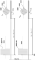
- a pulsed electronic excitation waveform 305 is shown with a normalized ordinate axis in a coordinate system.
- the horizontal axis represents the time in microseconds and the Tx parameter shown is the frequency variation over time.
- a first electronic excitation waveform 305 is generated by a controller and sent as an ultrasonic wave packet via the transmitter Tx (e.g. Tx 210, Figure 1 ) to receiver Rx.
- the received wave packet is then sampled.
- receiver Rx acts as transmitter and converts a second electronic excitation waveform 305 to an ultrasonic wave packet sent in the opposite direction of the fluid flow to the receiving transducer.
- the first and second electronic waveforms are different and differ in the Tx-parameter value.
- the first has a negative frequency chirp and the second has a positive frequency chirp.
- the variation of the frequency over time is implemented as a chirp 470 of the excitation waveform 305, i.e. a sweep of the number of oscillations per time unit, typically Hertz per micro second.
- the variation of the frequency is achieved by a shift of the waveform carrier frequency from one transducer excitation to the next, i.e. a shift of the waveform carrier frequency of excitation waveform 305.
- the frequency is lowered (negative chirp) compared to the previous constant frequency in the period 5 to 10 microseconds and in Figure 10B the frequency is increased (positive chirp) after 10 microseconds.
- piezoelectric transducers such as transducer 200 display resonant response not only at the fundamental frequency, but also at all the odd harmonics, it is also possible to vary the applied excitation frequencies to include the higher harmonic resonances of the transducers 200.
- Figure 10C shows examples of signals 330 ( Figure 1 ) after received wave packets 320 have been sampled.
- the received wave packets 330 have been under-sampled at 6/10 th of the central carrier frequency with the excitation frequency linearly ramped between 95 % and 105 % of the central carrier frequency.
- the asterisks correspond to a positive ramp (chirp) 470+ of frequency as shown in Figure 10B and the crosses correspond to a negative ramp (chirp) 470- as shown in Figure 10A .
- the Tx-parameter 400 is a transmittal-offset-parameter 420 in time and the offset is from a power up (i.e. a start-time) 302 to the time of transmittal of a wave packet 300.
- a power up i.e. a start-time
- Figure 12 illustrates a definition of the transmittal-offset-parameter 420.
- the transmitter start time 425 is offset by a transmittal offset ⁇ , pos 420.
- Figure 12 illustrates two different values of transmittal-offset-parameter 420 indexed as A and B, respectively.
- the transmittal offset ⁇ is zero, in B it has a non-zero value, for example in the range of 0,5 to 2 microseconds.
- excitation waveform 305B is sent to transmitter 210 and an ultrasonic wave packet 300 is received at receiver/transmitter 210.
- a sampling start time t a (pos. 350) is illustrated.
- Sampling graphic 1220 shows how the received wave packet 320B is converted into in a sampled wave packet 330B. In these two examples - A and B - the sampling frequency fs is held constant.
- the ultrasonic transducers 200 Due to the resonant nature of the ultrasonic transducers 200, these are prone to become excited not only by the electronic excitation waveform 305 but by any electrical influences coming from the circuit. Examples of such influences are electric voltage spikes and surges originating when powering up the electronic circuit, or supply-voltage variations or leakage from the oscillator into the circuit, external noise, etc.
- the result of these perturbations is that the transducers 200 are already oscillating to some extent when they are excited by the excitation waveform 305 or the opposite transducer 200 is already oscillating when receiving the ultrasound wave packet 300.
- the measured phase difference ⁇ ⁇ (position 520, phase difference between signal 330A and 330B) will reflect these parasitic oscillations by having received an additional contribution, which depends critically on timing of power up and switching of transducers 200, gas/water temperature, flowrate 110, etc. Hence, the contribution to the phase difference 520 is not well defined and cannot easily be controlled and/or compensated for. This effect is not limited to flow measurement systems where the signal is digitally sampled, but also to analogue systems or systems utilizing time-to-digital converters which will suffer from such parasitic oscillations. Hence, all afore mentioned systems will benefit from toggling of the excitation waveforms.
- phase differences 520 are usually slowly varying.
- One manner is to average the perturbations to become negligible.
- the time such as the transmitter start time 425 and thus the transmittal offset 420, between the circuit power-up and the sending of the excitation waveform 305.
- this transmitter time is denoted t w and its variation, the transmittal offset 420, is denoted ⁇ .
- Figure 11 illustrates Tx-parameter variations of the transmittal offset parameter 420, resulting in several different received wave packets 320.
- the transmittal offset ⁇ is zero the sampled values corresponds to the four asterisk in the time period from 5 microseconds to 10 microseconds.
- the value of the transmittal offset parameter 420 ⁇ set to 2/10 ts the sampled values in the same time period corresponds to the three crosses.
- the sampled values obtained with one value of offset ⁇ is different from the sampled values obtained with another value of offset ⁇
- the transmittal offset ⁇ can be chosen from any arbitrary set which may be exceeding t s both in the positive and negative direction.
- the Tx-parameter is a phase-parameter 450A or 450B as outlined in Figure 13 .
- Excitation waveform 305A starts with a positive pulse for 180 degrees and then has a negative pulse for 180 degrees.
- the Tx parameter phase has the parameter value zero.
- Excitation waveform 450B starts with a positive pulse for 90 degrees which pulse then goes to negative for 180 degrees.
- excitation waveform 305B end with a positive 90 degrees pulse.
- the Tx parameter of excitation waveform 305B has the parameter value 90.
- Excitation waveform 305B has a start phase and an end phase which is different from the start and end phase of excitation waveform 305A.
- the timing of the excitation waveform 305, the transmitter start time 425, is kept fixed relative to circuit power-up and digital sampling of the received wave packet 320, but the phase of the waveform 305 is varied as 450A and 450B, respectively. It may be particularly advantageous to vary the start and/or end phase of the excitation signals 305A or 305B in steps of 90 degrees as this cover two orthogonal quadratures of the oscillation, e.g. sines and cosines.
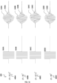
- Figure 14 illustrates aspects of applying different values of Tx phase parameters 450A, 450B, 450C and 450D.
- a better resolution can be obtained by choosing not only 0 and 90 degrees (say sine and cosine) phase difference between two signals, but extending the chosen phases 450A-D to cover the whole oscillation period from 0 to 360 degrees.
- Excitation signal 305A has a starting pulse and an ending pulse where the value of the excitation phase parameter ⁇ is 22,5 degrees.
- excitation signals 305B, 305C and 305D have values of 45 degrees, 67,5 degrees and 90 degrees respectively.
- the phase difference ⁇ (pos. 520) can be determined from a co- and counter-propagating signal and the resolution as well as accuracy of ⁇ can be improved by averaging as determining the flow rate 1300.
- the Tx-parameter is a polarity-parameter as illustrated in Figure 15 , pos. 430A and 430B.
- This embodiment is a single change of the Tx-parameter, a special case of the previous embodiment where the phase ⁇ of the excitation waveform 305 is toggled in its polarity. Instead of being positive between 0 and 180 degrees it is changed to being negative between 0 and 180 degrees as seen in a comparison between 305A and 305B of Figure 15 .
- the polarity (sign) 430 of the excitation waveform 305 and thus the ultrasonic wave packet 300 is changed.
- Figure 15 illustrates the excitation waveforms 305A,B and the resulting received wave packets 320A and 320B.
- the received signals 320A and 320B both suffer from offset errors and an overlapping sinusoidal oscillation with fixed phase relative to the sampling.
- Tx-parameter types 405 of Tx-parameters 400 as illustrated in Figure 10 (chirping 470, phase 450), Figures 11 to 12 , (transmittal offset 420) and Figures 15-16 (polarity 430) as well as changing say amplitude 460 or frequency 440 and make use of such variates in the act of determining the flow rate.
- the act of determining the flow rate as outlined in Figures 7-8 is performed as a function of different and combined Tx-parameter types.
- a preferred embodiment is where the method 1050 is performed with one Tx-parameter of the type transmittal-offset 420 and another Tx-parameter of the polarity 430.
- the invention discloses one or more of the following items:
Landscapes
- Physics & Mathematics (AREA)
- Electromagnetism (AREA)
- Fluid Mechanics (AREA)
- General Physics & Mathematics (AREA)
- Measuring Volume Flow (AREA)
- Ultra Sonic Daignosis Equipment (AREA)
Applications Claiming Priority (3)
| Application Number | Priority Date | Filing Date | Title |
|---|---|---|---|
| DKPA201970401 | 2019-06-25 | ||
| EP20735478.8A EP3990871A1 (de) | 2019-06-25 | 2020-06-25 | Ultraschall-durchflussmesser und verfahren zur bestimmung einer flussrate |
| PCT/DK2020/050190 WO2020259781A1 (en) | 2019-06-25 | 2020-06-25 | Ultrasonic flow meter and a method of determining a flow rate |
Related Parent Applications (1)
| Application Number | Title | Priority Date | Filing Date |
|---|---|---|---|
| EP20735478.8A Division EP3990871A1 (de) | 2019-06-25 | 2020-06-25 | Ultraschall-durchflussmesser und verfahren zur bestimmung einer flussrate |
Publications (2)
| Publication Number | Publication Date |
|---|---|
| EP4549886A2 true EP4549886A2 (de) | 2025-05-07 |
| EP4549886A3 EP4549886A3 (de) | 2025-07-30 |
Family
ID=71409073
Family Applications (2)
| Application Number | Title | Priority Date | Filing Date |
|---|---|---|---|
| EP25152742.0A Pending EP4549886A3 (de) | 2019-06-25 | 2020-06-25 | Ultraschalldurchflussmesser und verfahren zur bestimmung einer durchflussrate |
| EP20735478.8A Pending EP3990871A1 (de) | 2019-06-25 | 2020-06-25 | Ultraschall-durchflussmesser und verfahren zur bestimmung einer flussrate |
Family Applications After (1)
| Application Number | Title | Priority Date | Filing Date |
|---|---|---|---|
| EP20735478.8A Pending EP3990871A1 (de) | 2019-06-25 | 2020-06-25 | Ultraschall-durchflussmesser und verfahren zur bestimmung einer flussrate |
Country Status (2)
| Country | Link |
|---|---|
| EP (2) | EP4549886A3 (de) |
| WO (1) | WO2020259781A1 (de) |
Citations (4)
| Publication number | Priority date | Publication date | Assignee | Title |
|---|---|---|---|---|
| WO2011134470A2 (en) | 2010-04-28 | 2011-11-03 | Miitors Aps | Ultrasonic flow meter |
| WO2012055413A2 (en) | 2010-10-27 | 2012-05-03 | Kamstrup A/S | Ultrasonic flow meter with zero impedance measuring electronics |
| EP2581715A1 (de) | 2011-10-13 | 2013-04-17 | Miitors ApS | Ultraschalldurchflussmesser |
| WO2018006912A1 (en) | 2016-07-08 | 2018-01-11 | Apator Miitors Aps | Ultrasonic flow meter with improved adc arrangement |
Family Cites Families (8)
| Publication number | Priority date | Publication date | Assignee | Title |
|---|---|---|---|---|
| NZ243294A (en) * | 1991-06-25 | 1995-04-27 | Commw Scient Ind Res Org | Time of flight of acoustic wave packets through fluid: reduction of higher order acoustic mode effects |
| NZ243293A (en) * | 1991-06-25 | 1995-03-28 | Commw Scient Ind Res Org | Fluid flow meter: time of travel of acoustic wave packet through fluid |
| AUPQ061399A0 (en) * | 1999-05-27 | 1999-06-17 | University Of Sydney, The | Acoustic flow meters |
| AUPQ480199A0 (en) * | 1999-12-22 | 2000-02-03 | AGL Consultancy Pty. Limited | Timed window ultrasonic gas meter with nose cone |
| JP4983787B2 (ja) * | 2008-12-24 | 2012-07-25 | 横河電機株式会社 | 超音波計測器 |
| EP4134636B1 (de) * | 2011-12-02 | 2025-05-14 | Kamstrup A/S | Ultraschalldurchflussmesser mit digital unterabgetasteten durchflussmessungen |
| US10309813B2 (en) * | 2015-05-15 | 2019-06-04 | Reliance Worldwide Corporation | Method and system for fluid flow rate measurement |
| GB201713895D0 (en) * | 2017-08-30 | 2017-10-11 | Sentec Ltd | Transducer drive and damping technique |
-
2020
- 2020-06-25 EP EP25152742.0A patent/EP4549886A3/de active Pending
- 2020-06-25 EP EP20735478.8A patent/EP3990871A1/de active Pending
- 2020-06-25 WO PCT/DK2020/050190 patent/WO2020259781A1/en not_active Ceased
Patent Citations (4)
| Publication number | Priority date | Publication date | Assignee | Title |
|---|---|---|---|---|
| WO2011134470A2 (en) | 2010-04-28 | 2011-11-03 | Miitors Aps | Ultrasonic flow meter |
| WO2012055413A2 (en) | 2010-10-27 | 2012-05-03 | Kamstrup A/S | Ultrasonic flow meter with zero impedance measuring electronics |
| EP2581715A1 (de) | 2011-10-13 | 2013-04-17 | Miitors ApS | Ultraschalldurchflussmesser |
| WO2018006912A1 (en) | 2016-07-08 | 2018-01-11 | Apator Miitors Aps | Ultrasonic flow meter with improved adc arrangement |
Also Published As
| Publication number | Publication date |
|---|---|
| WO2020259781A1 (en) | 2020-12-30 |
| EP3990871A1 (de) | 2022-05-04 |
| EP4549886A3 (de) | 2025-07-30 |
Similar Documents
| Publication | Publication Date | Title |
|---|---|---|
| US6305233B1 (en) | Digital speed determination in ultrasonic flow measurements | |
| US7046015B2 (en) | Ultrasonic distance measure | |
| KR101113772B1 (ko) | 초음파 유량계 | |
| US6575044B1 (en) | Transit-time flow sensor combining high resolution and wide dynamic range | |
| KR20080039494A (ko) | 저 전력 초음파 유량 측정 | |
| US6829948B2 (en) | Flow meter | |
| EP3299774A1 (de) | Ultraschalldurchflussmesser und verfahren mit verwendung partieller durchflussmessungen | |
| CN104303023A (zh) | 流量测量装置 | |
| WO2002103299A1 (en) | Ultrasonic current meter | |
| CN105527192A (zh) | 用于测量流体密度的方法 | |
| EP2642256B1 (de) | Messanordnung und Verfahren | |
| EP1921424A1 (de) | Gerät zum messen des durchflusses einer flüssigkeit | |
| CN102203601A (zh) | 确定周期性振荡信号响应的起始时刻的方法 | |
| JP2003014515A (ja) | 超音波流量計 | |
| US20070203667A1 (en) | Positional information detecting method and device | |
| JP2002318145A (ja) | 流量計 | |
| WO2020259781A1 (en) | Ultrasonic flow meter and a method of determining a flow rate | |
| CN103635956B (zh) | 用于声学转换器的主动阻尼的方法和装置 | |
| US7617738B2 (en) | Method and apparatus for measuring flow rate of fluid | |
| JP2003329502A (ja) | 超音波流量計および超音波流量計の自己診断方法 | |
| Bo et al. | Forced oscillation to reduce zero flow error and thermal drift for non-reciprocal operating liquid ultrasonic flow meters | |
| JPH06288993A (ja) | 超音波式多成分濃度計 | |
| JP2008185441A (ja) | 超音波流量計 | |
| RU88460U1 (ru) | Ультразвуковой расходомер (варианты) | |
| JP2008175668A (ja) | 流体の流れ計測装置 |
Legal Events
| Date | Code | Title | Description |
|---|---|---|---|
| PUAI | Public reference made under article 153(3) epc to a published international application that has entered the european phase |
Free format text: ORIGINAL CODE: 0009012 |
|
| STAA | Information on the status of an ep patent application or granted ep patent |
Free format text: STATUS: THE APPLICATION HAS BEEN PUBLISHED |
|
| AC | Divisional application: reference to earlier application |
Ref document number: 3990871 Country of ref document: EP Kind code of ref document: P |
|
| AK | Designated contracting states |
Kind code of ref document: A2 Designated state(s): AL AT BE BG CH CY CZ DE DK EE ES FI FR GB GR HR HU IE IS IT LI LT LU LV MC MK MT NL NO PL PT RO RS SE SI SK SM TR |
|
| PUAL | Search report despatched |
Free format text: ORIGINAL CODE: 0009013 |
|
| AK | Designated contracting states |
Kind code of ref document: A3 Designated state(s): AL AT BE BG CH CY CZ DE DK EE ES FI FR GB GR HR HU IE IS IT LI LT LU LV MC MK MT NL NO PL PT RO RS SE SI SK SM TR |
|
| RIC1 | Information provided on ipc code assigned before grant |
Ipc: G01F 1/66 20220101AFI20250624BHEP Ipc: G01F 1/667 20220101ALI20250624BHEP |
|
| STAA | Information on the status of an ep patent application or granted ep patent |
Free format text: STATUS: REQUEST FOR EXAMINATION WAS MADE |
|
| 17P | Request for examination filed |
Effective date: 20260129 |