EP4549867A1 - Harmonica-shaped tube, harmonica-shaped tube type heat exchanger and vehicle - Google Patents
Harmonica-shaped tube, harmonica-shaped tube type heat exchanger and vehicle Download PDFInfo
- Publication number
- EP4549867A1 EP4549867A1 EP23830368.9A EP23830368A EP4549867A1 EP 4549867 A1 EP4549867 A1 EP 4549867A1 EP 23830368 A EP23830368 A EP 23830368A EP 4549867 A1 EP4549867 A1 EP 4549867A1
- Authority
- EP
- European Patent Office
- Prior art keywords
- harmonica
- tube
- flow channel
- collecting tube
- tubes
- Prior art date
- Legal status (The legal status is an assumption and is not a legal conclusion. Google has not performed a legal analysis and makes no representation as to the accuracy of the status listed.)
- Pending
Links
Images



Classifications
-
- F—MECHANICAL ENGINEERING; LIGHTING; HEATING; WEAPONS; BLASTING
- F28—HEAT EXCHANGE IN GENERAL
- F28F—DETAILS OF HEAT-EXCHANGE AND HEAT-TRANSFER APPARATUS, OF GENERAL APPLICATION
- F28F1/00—Tubular elements; Assemblies of tubular elements
- F28F1/02—Tubular elements of cross-section which is non-circular
- F28F1/022—Tubular elements of cross-section which is non-circular with multiple channels
-
- F—MECHANICAL ENGINEERING; LIGHTING; HEATING; WEAPONS; BLASTING
- F28—HEAT EXCHANGE IN GENERAL
- F28D—HEAT-EXCHANGE APPARATUS, NOT PROVIDED FOR IN ANOTHER SUBCLASS, IN WHICH THE HEAT-EXCHANGE MEDIA DO NOT COME INTO DIRECT CONTACT
- F28D7/00—Heat-exchange apparatus having stationary tubular conduit assemblies for both heat-exchange media, the media being in contact with different sides of a conduit wall
- F28D7/16—Heat-exchange apparatus having stationary tubular conduit assemblies for both heat-exchange media, the media being in contact with different sides of a conduit wall the conduits being arranged in parallel spaced relation
-
- B—PERFORMING OPERATIONS; TRANSPORTING
- B60—VEHICLES IN GENERAL
- B60L—PROPULSION OF ELECTRICALLY-PROPELLED VEHICLES; SUPPLYING ELECTRIC POWER FOR AUXILIARY EQUIPMENT OF ELECTRICALLY-PROPELLED VEHICLES; ELECTRODYNAMIC BRAKE SYSTEMS FOR VEHICLES IN GENERAL; MAGNETIC SUSPENSION OR LEVITATION FOR VEHICLES; MONITORING OPERATING VARIABLES OF ELECTRICALLY-PROPELLED VEHICLES; ELECTRIC SAFETY DEVICES FOR ELECTRICALLY-PROPELLED VEHICLES
- B60L50/00—Electric propulsion with power supplied within the vehicle
- B60L50/50—Electric propulsion with power supplied within the vehicle using propulsion power supplied by batteries or fuel cells
-
- F—MECHANICAL ENGINEERING; LIGHTING; HEATING; WEAPONS; BLASTING
- F28—HEAT EXCHANGE IN GENERAL
- F28D—HEAT-EXCHANGE APPARATUS, NOT PROVIDED FOR IN ANOTHER SUBCLASS, IN WHICH THE HEAT-EXCHANGE MEDIA DO NOT COME INTO DIRECT CONTACT
- F28D21/00—Heat-exchange apparatus not covered by any of the groups F28D1/00 - F28D20/00
-
- F—MECHANICAL ENGINEERING; LIGHTING; HEATING; WEAPONS; BLASTING
- F28—HEAT EXCHANGE IN GENERAL
- F28F—DETAILS OF HEAT-EXCHANGE AND HEAT-TRANSFER APPARATUS, OF GENERAL APPLICATION
- F28F1/00—Tubular elements; Assemblies of tubular elements
- F28F1/10—Tubular elements and assemblies thereof with means for increasing heat-transfer area, e.g. with fins, with projections, with recesses
- F28F1/40—Tubular elements and assemblies thereof with means for increasing heat-transfer area, e.g. with fins, with projections, with recesses the means being only inside the tubular element
-
- F—MECHANICAL ENGINEERING; LIGHTING; HEATING; WEAPONS; BLASTING
- F28—HEAT EXCHANGE IN GENERAL
- F28F—DETAILS OF HEAT-EXCHANGE AND HEAT-TRANSFER APPARATUS, OF GENERAL APPLICATION
- F28F9/00—Casings; Header boxes; Auxiliary supports for elements; Auxiliary members within casings
- F28F9/02—Header boxes; End plates
-
- H—ELECTRICITY
- H01—ELECTRIC ELEMENTS
- H01M—PROCESSES OR MEANS, e.g. BATTERIES, FOR THE DIRECT CONVERSION OF CHEMICAL ENERGY INTO ELECTRICAL ENERGY
- H01M10/00—Secondary cells; Manufacture thereof
- H01M10/60—Heating or cooling; Temperature control
- H01M10/61—Types of temperature control
- H01M10/613—Cooling or keeping cold
-
- H—ELECTRICITY
- H01—ELECTRIC ELEMENTS
- H01M—PROCESSES OR MEANS, e.g. BATTERIES, FOR THE DIRECT CONVERSION OF CHEMICAL ENERGY INTO ELECTRICAL ENERGY
- H01M10/00—Secondary cells; Manufacture thereof
- H01M10/60—Heating or cooling; Temperature control
- H01M10/62—Heating or cooling; Temperature control specially adapted for specific applications
- H01M10/625—Vehicles
-
- H—ELECTRICITY
- H01—ELECTRIC ELEMENTS
- H01M—PROCESSES OR MEANS, e.g. BATTERIES, FOR THE DIRECT CONVERSION OF CHEMICAL ENERGY INTO ELECTRICAL ENERGY
- H01M10/00—Secondary cells; Manufacture thereof
- H01M10/60—Heating or cooling; Temperature control
- H01M10/65—Means for temperature control structurally associated with the cells
- H01M10/655—Solid structures for heat exchange or heat conduction
- H01M10/6552—Closed pipes transferring heat by thermal conductivity or phase transition, e.g. heat pipes
-
- F—MECHANICAL ENGINEERING; LIGHTING; HEATING; WEAPONS; BLASTING
- F28—HEAT EXCHANGE IN GENERAL
- F28D—HEAT-EXCHANGE APPARATUS, NOT PROVIDED FOR IN ANOTHER SUBCLASS, IN WHICH THE HEAT-EXCHANGE MEDIA DO NOT COME INTO DIRECT CONTACT
- F28D21/00—Heat-exchange apparatus not covered by any of the groups F28D1/00 - F28D20/00
- F28D2021/0019—Other heat exchangers for particular applications; Heat exchange systems not otherwise provided for
- F28D2021/008—Other heat exchangers for particular applications; Heat exchange systems not otherwise provided for for vehicles
-
- F—MECHANICAL ENGINEERING; LIGHTING; HEATING; WEAPONS; BLASTING
- F28—HEAT EXCHANGE IN GENERAL
- F28F—DETAILS OF HEAT-EXCHANGE AND HEAT-TRANSFER APPARATUS, OF GENERAL APPLICATION
- F28F9/00—Casings; Header boxes; Auxiliary supports for elements; Auxiliary members within casings
- F28F9/02—Header boxes; End plates
- F28F9/0246—Arrangements for connecting header boxes with flow lines
- F28F9/0251—Massive connectors, e.g. blocks; Plate-like connectors
- F28F9/0253—Massive connectors, e.g. blocks; Plate-like connectors with multiple channels, e.g. with combined inflow and outflow channels
-
- Y—GENERAL TAGGING OF NEW TECHNOLOGICAL DEVELOPMENTS; GENERAL TAGGING OF CROSS-SECTIONAL TECHNOLOGIES SPANNING OVER SEVERAL SECTIONS OF THE IPC; TECHNICAL SUBJECTS COVERED BY FORMER USPC CROSS-REFERENCE ART COLLECTIONS [XRACs] AND DIGESTS
- Y02—TECHNOLOGIES OR APPLICATIONS FOR MITIGATION OR ADAPTATION AGAINST CLIMATE CHANGE
- Y02E—REDUCTION OF GREENHOUSE GAS [GHG] EMISSIONS, RELATED TO ENERGY GENERATION, TRANSMISSION OR DISTRIBUTION
- Y02E60/00—Enabling technologies; Technologies with a potential or indirect contribution to GHG emissions mitigation
- Y02E60/10—Energy storage using batteries
Definitions
- the power battery direct cooling heat exchanger is mainly formed by welding a harmonica tube, a collecting tube assembly, a tail end collecting tube, a connector and a temperature equalizing plate in the related art. Meanwhile, a flow channel is arranged in the harmonica tube, and the refrigerant mainly performs boiling heat transfer rather than convection heat transfer in the harmonica tube.
- the recess is formed on the inner sidewall of the flow channel and penetrates through the flow channel along the length direction of the flow channel;
- a harmonica tube heat exchanger which includes a collecting tube assembly, a tail end collecting tube, a connector, a temperature equalizing plate, and a plurality of the foregoing harmonica tubes;
- the number of the harmonica tubes is eight, in a direction perpendicular to the extension direction of the harmonica tubes, the first ends of the four harmonica tubes on the innermost side are respectively in communication with the second collecting tube, and the first ends of the other four harmonica tubes are in communication with the first collecting tube.
- the first collecting tube is provided with a plurality of first strip-shaped holes extending along the length direction of the first collecting tube, and the first end of the harmonica tube is fixedly connected with the first strip-shaped holes, causing a plurality of flow channels of the harmonica tube can be in communication with the first collecting tube;
- the terms “upper”, “lower”, “left” and “right” are used generally to refer to upper, lower, left and right corresponding to the figures, and “inner” and “outer” refer to “ inner and outer” relative to the contour of the corresponding component itself .
- the terms “first”, “second”, “third”, “fourth”, and the like are used in the present disclosure to distinguish one element from another and are not sequential or important.
- the same reference numerals in different drawings indicate the same or similar elements unless otherwise explained. The mentioned above definitions are for purposes of explanation and description of the present disclosure only and should not be construed as limiting the present disclosure.
- the power battery direct cooling heat exchanger is mainly formed by welding a harmonica tube, a collecting tube assembly, a tail end collecting tube, a connector and a temperature equalizing plate in the related art.
- the refrigerant in the harmonica tube will gradually change from liquid to gas-liquid two-phase, and may eventually become gaseous. Therefore, the heat transfer performs boiling heat transfer rather than convection heat transfer in the harmonica tube. According to the characteristics of boiling heat transfer, we need the liquid refrigerant in the harmonica tube to be able to quickly nucleate and detach from the wall surface, so as to have the best heat exchange capacity.
- the inner sidewall of the flow channel 11 in the harmonica tube 10 is smooth, the refrigerant enters from one end and flows out from the other end, and the speed when the refrigerant contacts the wall surface in the flow channel 11 is too fast, which is unfavorable for nucleation, and after nucleation, when the fluid (refrigerant) flows inside the harmonica tube 10, a boundary layer is formed on the inner sidewall surface of the flow channel 11 of the harmonica tube 10, and the boundary layer will hinder the heat exchange of the fluid.
- the conventional harmonica tube 10 is likely to have slow nucleation rate of the refrigerant, and at the same time, the nuclei grows from a small nuclei to a large nuclei, or the liquid nuclei always swims on the wall surface and cannot be quickly detached from the wall surface, and the like, which will seriously affect the heat exchange capacity of the direct cooling heat exchanger, especially under the condition of high heat generation of a power battery, and it is particularly important to design a harmonica tube capable of enhancing heat transfer.
- a harmonica tube 100 includes a plurality of flow channels 110 which are arranged at intervals, wherein the inner sidewall of at least a portion of the flow channels 110 is provided with a protrusion 111 protruding towards near the center direction of the flow channels 110 and/or a recess 112 recessed towards the center direction away from the flow channels 110.
- the protrusion 111 and/or the recess 112 is/are arranged on the inner sidewalls of the plurality of flow channels 110 or a portion of the flow channels110 , and the protrusion 111 and the recess 112 can be used as gasification core, causing the liquid fluid (refrigerant) can be quickly nucleated and vaporized, meanwhile, they can also break the disordered growth of large nuclei (bubbles) after nucleation, causing them to quickly detach from the wall of the flow channel 110, preventing the formation of a boundary layer on the inner sidewall surface of the flow channel by the nucleated large nuclei (bubbles), improving the heat transfer capacity of the harmonica tube 100, and meeting the heat transfer needs of power battery 600.
- each flow channel 110 may be provided with a protrusion 111 or a recess 112, or a protrusion 111 and a recess 112at the same time, to avoid that the fluid cannot be nucleated due to the rapid flow along the inner sidewall surface of the flow channel, and to avoid forming boundary layers on the inner sidewall, and to improve the boiling heat transfer capability of the harmonica tube 100 to meet the high heat exchange requirements of the power battery 600 at present and even in the future.
- each flow channel 110 is provided with a protrusion 111 and/or a recess 112, so as to maximize the heat exchange capacity of the whole harmonica tube 100; of course, the protrusion 111 and/or the recess 112 can also be arranged on the inner sidewall of part of the flow channels 110 (one flow channel 110 or more than one flow channel 110) in the plurality of flow channels 110, so as to improve the heat exchange capacity of the whole harmonica tube 100 to a certain extent.
- the number of the flow channels 110 provided with the protrusions 111 and/or the recesses 112 can be selected by a technician as desired.
- the protrusion 111 when the protrusion 111 is disposed on the inner sidewall of the flow channel 110, the protrusion 111 may be configured with any suitable structure.
- the protrusion 111 may be formed on the inner sidewall of the flow channel 110, and the protrusion 111 penetrates through the flow channel 110 along the length direction of the flow channel 110.
- the protrusion 111 may extend along the length direction of the harmonica tube 100 and extend from one end of the flow channel 110 of the harmonica tube 100 to the other end.
- the protrusions111 may also be spirally arranged along the length direction of the flow channel 110, wherein the protrusion 111 may have a protruding structure continuous in the length direction of the flow channel 110 and protruding towards the center direction of the flow channel 110, that is, the protrusion 111 may extend from one end of the flow channel 110 to the other end; of course, the protruding structure can also be configured as a plurality of sub protrusions arranged at intervals along the spiral direction, and also can play the role of improving the heat exchange effect.
- the spirally arranged protrusion 111 can be used as a gasification core under the condition that the refrigerant is overheated, which is beneficial to the nucleation of bubbles, and simultaneously prevents the disorderly growing nucleus from growing and adhering to the wall surface to form a boundary layer to influence heat exchange.
- the number of the protrusions 111 is plural, and the protrusions 111 are arranged at intervals along the length direction of the flow channel 110.
- the protrusions 111 can be configured as arc structures, triangular structures, rectangular structures or other polygonal structures, and are arranged at intervals along the length direction of the flow channel 110, that is, a plurality of disconnected protrusions 111 are arranged along the length direction, causing the nucleation of the refrigerant can be satisfied, the boundary layer can be broken, and the boiling heat exchange capacity can be improved.
- the recess 112 when the recess 112 is provided on the inner sidewall of the flow channel 110, the recess 112 may be configured with any suitable structure.
- the recess 112 is formed on the inner sidewall of the flow channel 110 and penetrates through the flow channel 110 along the length direction of the flow channel 110, wherein the recess 112 may extend along the length direction of the harmonica tube 100 and extend from one end to the other end of the flow channel 110 of the harmonica tube 100.
- the refrigerant When the refrigerant is overheated and flows in the flow channel 110, the refrigerant can be nucleated by using the recess 112 as a gasification core to form bubbles and flow along the flow channel 110. Meanwhile, the recess can also break the bubbles growing in disorder, so as to prevent the formation of a boundary layer on the inner sidewall surface of the flow channel 110 to influence the heat exchange.
- the recesses 112 are spirally arranged along the length direction of the flow channel 110.
- the recess 112 may have a recess structure that is continuous in the length direction of the flow channel 110 and recessed toward the center direction of the flow channel 110, that is, the recess structure may extend from one end of the flow channel 110 to the other end; of course, the recess structure can also be configured as a plurality of sub-grooves arranged at intervals along the spiral direction, and also can play the role of improving the heat exchange effect.
- the number of the recesses 112 may be plural, and the recesses 112 are arranged at intervals along the length direction of the flow channel 110.
- the recesses 112 can be configured as arc grooves, triangular grooves, rectangular grooves or other polygonal grooves, and are arranged at intervals along the length direction of the flow channel 110, that is, a plurality of disconnected recesses 112 are arranged along the length direction, causing the nucleation of the refrigerant can be satisfied, the boundary layer can be broken, and the boiling heat exchange capacity can be improved.
- the number of the protrusions 111 may be plural, and the protrusions 111 extend along the length direction of the flow channel 110 and are arranged at intervals along the circumferential direction of the flow channel 110.
- the plurality of protrusions 111 can be arranged at intervals along the length direction of the flow channel 110, and the plurality of protrusions 111 can be arranged at intervals along the circumferential direction of the flow channel 110.
- the plurality of protrusions 111 can be arranged on a plurality of straight lines or alternatively arranged.
- the plurality of protrusions 111 arranged in the length direction and the circumferential direction can be used as gasification cores for nucleation to form bubbles and flow along the flow channel 110. Meanwhile, the plurality of protrusions 111 can more effectively break the bubbles growing in disorder, so as to prevent the bubbles from forming boundary layers on the inner sidewall surface of the flow channel 110 and affecting heat exchange.
- the number of the recesses 112 may be plural, and the recesses 112 extend along the length direction of the flow channel 110 and are arranged at intervals along the circumferential direction of the flow channel 110.
- the plurality of recesses112 may be arranged at intervals along the length direction of the flow channel 110, and the plurality of recesses 112 may also be arranged at intervals along the circumferential direction of the flow channel 110.
- the plurality of recesses 112 may be arranged on a plurality of straight lines or alternatively arranged.
- the plurality of recesses 112 extend along the length direction and are arranged at intervals along the circumferential direction, causing the gasification core is increased and nucleated, the boundary layer can be effectively broken, and the heat exchange effect is improved.
- the number of harmonica tubes can be eight.
- the first ends 101 of the innermost four harmonica tubes 100 are respectively in communication with the second collecting tube 220, and the first ends 101 of the two harmonica tubes 100 positioned on both sides of the four harmonica tubes 100 are respectively in communication with the first collecting tube 210.
- the tail end collecting tube 300 is provided with a plurality of third strip-shaped holes 301 extending along the length direction thereof, and the second end 102 of the harmonica tube 100 is fixedly connected to the third strip-shaped holes 301, causing the plurality of flow channels 110 of the harmonica tube 100 can be in communication with the tail end collecting tube 300.
- a plurality of third strip-shaped holes 301 corresponding to the width of the second end 102 of the harmonica tube 100 to be connected are formed on the inner side of the tail end collecting tube 300, and the harmonica tube 100 is inserted into the third strip-shaped hole 301 and connected to the third strip-shaped hole 301 by welding.
- the second end 102 of the harmonica tube 100 is a straight section, causing the second end 102 of the harmonica tube 100 can be directly disposed at the third strip-shaped holes 301, and then the harmonica tube 100 and the tail end collecting tube 300 are connected by brazing, causing the problem of blocking the flow channel 110 of the second end 102 of the harmonica tube 100 is not required, and the assembly efficiency can be improved.
- the tail end collecting tube 300 may also be a round aluminum tube, both ends of the round aluminum tube are sealed, and the second ends 102 of the plurality of harmonica tubes 100 are connected to the round aluminum tube at intervals, causing the refrigerant can flow in part of the harmonica tubes 100and flow out from other parts of the harmonica tubes 100.
- the sealing member 310 for blocking the internal channel can be arranged at the middle position of the round aluminum tube to divide the round tube into two sections, wherein the four harmonica tubes 100 on the left side are in communication with one section, and the four harmonica tubes 100 on the right side are in communication with the other section, causing the purpose of stabilizing the flow rate can also be realized.
- a vehicle 1000 which includes a power battery 600.
- the vehicle 1000 further includes the harmonica tube heat exchanger 1001 described above. Since the harmonica heat exchanger 1001 adopts a structural design in which the flow channel 110 is provided with the protrusion 111 and/or the recess 112, the power battery 600 of the vehicle 1000 can be better cooled or heated.
- the harmonica tube heat exchanger 1001 and the vehicle 1000 of the present disclosure it is considered that boiling heat transfer, particularly forced boiling, occupies a dominant position in the harmonica tube heat exchanger 1001. Therefore, according to the characteristics of forced boiling and the characteristics of liquid nucleation during boiling, the structural design for enhancing heat transfer is carried out by arranging the protrusion 111 and/or the recess 112 on the inner sidewall of the whole flow channel 110 or part of the flow channel 110 of the harmonica tube 100, causing the liquid nucleation speed can be increased, and meanwhile, the nuclei can be restricted to be constantly enlarged to form a film to hinder heat transfer, the heat exchange capability of the harmonica tube 100 is improved, and the heat exchange requirement of the power battery 600 is met.
- image information at a same angle as a rearview mirror may be captured by using left and right cameras respectively installed on the rearview mirror of the vehicle, and is processed to determine whether an obstacle or pedestrian is provided within a range.
- rear image information is collected by using a millimeter wave radar installed in the rear of the vehicle, to determine, based on the rear image information, whether an oncoming vehicle is provided behind the vehicle.
- image information on both sides of the vehicle is collected by using an ultrasonic radar installed on a vehicle body.
Landscapes
- Engineering & Computer Science (AREA)
- Physics & Mathematics (AREA)
- Mechanical Engineering (AREA)
- General Engineering & Computer Science (AREA)
- Thermal Sciences (AREA)
- Electrochemistry (AREA)
- General Chemical & Material Sciences (AREA)
- Manufacturing & Machinery (AREA)
- Chemical & Material Sciences (AREA)
- Chemical Kinetics & Catalysis (AREA)
- Geometry (AREA)
- Transportation (AREA)
- Power Engineering (AREA)
- Sustainable Energy (AREA)
- Sustainable Development (AREA)
- Life Sciences & Earth Sciences (AREA)
- Heat-Exchange Devices With Radiators And Conduit Assemblies (AREA)
- Secondary Cells (AREA)
- Cooling, Air Intake And Gas Exhaust, And Fuel Tank Arrangements In Propulsion Units (AREA)
- Arrangement Or Mounting Of Propulsion Units For Vehicles (AREA)
Abstract
Description
- The present disclosure claims priority to
Chinese Patent Application No. 202210772676.7, filed on June 30,2022 - The present disclosure relates to the field of battery heat exchanger, and in particular, to a harmonica tube, a harmonica tube heat exchanger and a vehicle.
- The power battery direct cooling heat exchanger is mainly formed by welding a harmonica tube, a collecting tube assembly, a tail end collecting tube, a connector and a temperature equalizing plate in the related art. Meanwhile, a flow channel is arranged in the harmonica tube, and the refrigerant mainly performs boiling heat transfer rather than convection heat transfer in the harmonica tube. The inner wall of the flow channel of the harmonica tube is smooth, and the refrigerant enters from one end and flows out from the other end, on the one hand, the contact time between the refrigerant and the inner wall surface is too short, which is not conducive to nucleation; on the other hand, once nucleated, the nucleus always swims along the inner wall surface and cannot be detached from the wall surface rapidly, causing the heat exchange capacity is obviously reduced.
- The present disclosure is intended to provide a harmonica tube, a harmonica tube heat exchanger and a vehicle, wherein the harmonica tube can improve boiling heat transfer capacity through a protrusion and/or a recess formed on the inner sidewall of a flow channel of the harmonica tube so as to overcome the technical problem of insufficient heat exchange capacity of the conventional harmonica tube.
- In order to achieve the above object, in a first aspect of the present disclosure, a harmonica tube includes a plurality of flow channels which are arranged at intervals, wherein at least part of the inner sidewall of the flow channels is provided with a protrusion protruding towards near the center direction of the flow channels and/or provided with a recess recessed towards the center direction away from the flow channels.
- In an embodiment, the protrusion is formed on the inner sidewall of the flow channel and penetrates through the flow channel along the length direction of the flow channel;
- or the protrusion is spirally arranged along the length direction of the flow channel;
- or the number of the protrusions is plural, and the plurality of the protrusions are arranged at intervals along the length direction of the flow channel.
- In an embodiment, the recess is formed on the inner sidewall of the flow channel and penetrates through the flow channel along the length direction of the flow channel;
- or the recess is spirally arranged along the length direction of the flow channel;
- or the number of the recesses is plural, and the plurality of the recesses are arranged at intervals along the length direction of the flow channel.
- In an embodiment, the number of the protrusions is plural, the plurality of protrusions extend along the length direction of the flow channel and are arranged at intervals along the circumferential direction of the flow channel;
or the number of the recesses is plural, and the plurality of recesses extend along the length direction of the flow channel and are arranged at intervals along the circumferential direction of the flow channel. - In an embodiment, the number of the protrusions is two, and the two protrusions are arranged on two opposite side surfaces of the flow channel.
- In a second aspect of the present disclosure, a harmonica tube heat exchanger is provided, which includes a collecting tube assembly, a tail end collecting tube, a connector, a temperature equalizing plate, and a plurality of the foregoing harmonica tubes;
- wherein the collecting tube assembly includes a first collecting tube and a second collecting tube; the inlet of the connector is in communication with the first end of a portion of the plurality of the harmonica tubes through the first collecting tube, and the outlet of the connector is in communication with the first end of another portion of the plurality of the harmonica tubes through the second collecting tube. The second ends of the plurality of the harmonica tubes are respectively in communication with the tail end collecting tube;
- and the plurality of the harmonica tubes are fixedly arranged on the temperature equalizing plate.
- In an embodiment, in a direction perpendicular to the extension direction of the harmonica tubes, at least two of the harmonica tubes positioned on the outermost side among the plurality of harmonica tubes communicate with the first collecting tube.
- In an embodiment, the number of the harmonica tubes is eight, in a direction perpendicular to the extension direction of the harmonica tubes, the first ends of the four harmonica tubes on the innermost side are respectively in communication with the second collecting tube, and the first ends of the other four harmonica tubes are in communication with the first collecting tube.
- In an embodiment, the first collecting tube is provided with a plurality of first strip-shaped holes extending along the length direction of the first collecting tube, and the first end of the harmonica tube is fixedly connected with the first strip-shaped holes, causing a plurality of flow channels of the harmonica tube can be in communication with the first collecting tube;
- and/or the second collecting tube is provided with a plurality of second strip-shaped holes extending along the length direction of the second collecting tube, and the first end of the harmonica tube is fixedly connected with the second strip-shaped holes, causing a plurality of flow channels of the harmonica tube can be in communication with the second collecting tube;
- and/or the tail end collecting tube is provided with a plurality of third strip-shaped holes extending along the length direction of the tail end collecting tube, and the second end of the harmonica tube is fixedly connected with the third strip-shaped holes, causing a plurality of flow channels of the harmonica tube can be in communication with the tail end collecting tube.
- In a third aspect of the present disclosure, a vehicle including power battery is also provided, the vehicle further includes the foregoing harmonica tube heat exchanger.
- Through the technical scheme, that is, the harmonica tube of the present disclosure, the protrusion and/or the recess is/are arranged on the inner sidewalls of the plurality of flow channels or a portion of the plurality of the flow channels, and the protrusion and the recess can be used as gasification core, causing the liquid fluid (refrigerant) can be quickly nucleated and vaporized, meanwhile, they can also break the disordered growth of large nuclei (bubbles) after nucleation, causing them to quickly detach from the wall of the flow channel, preventing the formation of a boundary layer on the inner sidewall surface of the flow channel by the nucleated large nuclei (bubbles), improving the heat transfer capacity of the harmonica tube, and meeting the heat transfer needs of power battery.
- The additional aspects and advantages of the present disclosure will be described in detail in the following detailed descriptions.
- The drawings, which are included to provide a further understanding of the present disclosure and constitute a part of the description, together with the following detailed description, are used to explain the present disclosure and do not constitute an undue limitation of the present disclosure. In the drawings:
-
FIG. 1 is a schematic structural diagram of a harmonica tube of a conventional power battery direct cooling heat exchanger; -
FIG. 2 is a schematic structural diagram of a harmonica tube provided by some embodiments of the present disclosure; -
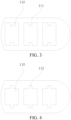
FIG. 3 is an enlarged view of part A infig. 2 ; -
FIG. 4 is a partial enlarged view of the a flow channel cross-section of a harmonica tube provided in other embodiments of the present disclosure; -
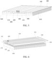
FIG. 5 is a schematic structural diagram of a harmonica tube heat exchanger provided by some embodiments of the present disclosure; -
FIG. 6 is an exploded view of the harmonica tube heat exchanger based onFIG. 5 ; -
FIG. 7 is a top view of a harmonica tube heat exchanger in some embodiments of the present disclosure, wherein the flow direction of the refrigerant in each harmonica tube is illustrated; -
FIG. 8 is a schematic structural diagram of a collecting tube assembly of a harmonica tube heat exchanger in some embodiments of the present disclosure, wherein the collecting tube assembly includes a first collecting tube and a second collecting tube; -
FIG. 9 is a schematic structural diagram of a tail end collecting tube of a harmonica tube heat exchanger in some embodiments of the present disclosure; -
FIG. 10 is a schematic structural diagram of a connector of a harmonica tube heat exchanger in some embodiments of the present disclosure; and -
FIG. 11 is a block diagram of a structure of a vehicle in an illustrative embodiment of the present disclosure. - It should be understood that the specific embodiments described herein are for purposes of illustration and explanation of the disclosure only and are not intended to limit the present disclosure.
- In the present disclosure, unless otherwise explicitly specified and limited, the terms "upper", "lower", "left" and "right" are used generally to refer to upper, lower, left and right corresponding to the figures, and "inner" and "outer" refer to " inner and outer" relative to the contour of the corresponding component itself . In addition, the terms "first", "second", "third", "fourth", and the like are used in the present disclosure to distinguish one element from another and are not sequential or important. In addition, in the following description, when referring to the drawings, the same reference numerals in different drawings indicate the same or similar elements unless otherwise explained. The mentioned above definitions are for purposes of explanation and description of the present disclosure only and should not be construed as limiting the present disclosure.
- The power battery direct cooling heat exchanger is mainly formed by welding a harmonica tube, a collecting tube assembly, a tail end collecting tube, a connector and a temperature equalizing plate in the related art. Different from liquid cooling, the refrigerant in the harmonica tube will gradually change from liquid to gas-liquid two-phase, and may eventually become gaseous. Therefore, the heat transfer performs boiling heat transfer rather than convection heat transfer in the harmonica tube. According to the characteristics of boiling heat transfer, we need the liquid refrigerant in the harmonica tube to be able to quickly nucleate and detach from the wall surface, so as to have the best heat exchange capacity. If that nucleation rate of the nuclei is too slow, or the speed of detaching from the wall surface after nucleation is too slow, or the nuclei continuously grows and even blocks the whole tube channel, the heat exchange capacity can be obviously reduced. However, the smooth inner sidewall of the harmonica tube at present has no way to make the liquid refrigerant nucleate rapidly, and once nucleated, it cannot be quickly detached from the wall surface.
- As shown in
FIG. 1 , in the related art, the inner sidewall of theflow channel 11 in theharmonica tube 10 is smooth, the refrigerant enters from one end and flows out from the other end, and the speed when the refrigerant contacts the wall surface in theflow channel 11 is too fast, which is unfavorable for nucleation, and after nucleation, when the fluid (refrigerant) flows inside theharmonica tube 10, a boundary layer is formed on the inner sidewall surface of theflow channel 11 of theharmonica tube 10, and the boundary layer will hinder the heat exchange of the fluid. In other words, theconventional harmonica tube 10 is likely to have slow nucleation rate of the refrigerant, and at the same time, the nuclei grows from a small nuclei to a large nuclei, or the liquid nuclei always swims on the wall surface and cannot be quickly detached from the wall surface, and the like, which will seriously affect the heat exchange capacity of the direct cooling heat exchanger, especially under the condition of high heat generation of a power battery, and it is particularly important to design a harmonica tube capable of enhancing heat transfer. - As shown in
FIG. 2 to FIG. 4 , in order to achieve the above object, in a first aspect of the present disclosure, aharmonica tube 100 includes a plurality offlow channels 110 which are arranged at intervals, wherein the inner sidewall of at least a portion of theflow channels 110 is provided with aprotrusion 111 protruding towards near the center direction of theflow channels 110 and/or arecess 112 recessed towards the center direction away from theflow channels 110. - Through the technical scheme, that is, the
harmonica tube 100 of the present disclosure, theprotrusion 111 and/or therecess 112 is/are arranged on the inner sidewalls of the plurality offlow channels 110 or a portion of the flow channels110 , and theprotrusion 111 and therecess 112 can be used as gasification core, causing the liquid fluid (refrigerant) can be quickly nucleated and vaporized, meanwhile, they can also break the disordered growth of large nuclei (bubbles) after nucleation, causing them to quickly detach from the wall of theflow channel 110, preventing the formation of a boundary layer on the inner sidewall surface of the flow channel by the nucleated large nuclei (bubbles), improving the heat transfer capacity of theharmonica tube 100, and meeting the heat transfer needs ofpower battery 600. - It should be noted that the inner sidewall of each
flow channel 110 may be provided with aprotrusion 111 or arecess 112, or aprotrusion 111 and a recess 112at the same time, to avoid that the fluid cannot be nucleated due to the rapid flow along the inner sidewall surface of the flow channel, and to avoid forming boundary layers on the inner sidewall, and to improve the boiling heat transfer capability of theharmonica tube 100 to meet the high heat exchange requirements of thepower battery 600 at present and even in the future. - It can be understood that in the plurality of
flow channels 110 of the harmonica tube, eachflow channel 110 is provided with aprotrusion 111 and/or arecess 112, so as to maximize the heat exchange capacity of thewhole harmonica tube 100; of course, theprotrusion 111 and/or therecess 112 can also be arranged on the inner sidewall of part of the flow channels 110 (oneflow channel 110 or more than one flow channel 110) in the plurality offlow channels 110, so as to improve the heat exchange capacity of thewhole harmonica tube 100 to a certain extent. The number of theflow channels 110 provided with theprotrusions 111 and/or therecesses 112 can be selected by a technician as desired. - As shown in
FIG. 2 andFIG. 3 , when theprotrusion 111 is disposed on the inner sidewall of theflow channel 110, theprotrusion 111 may be configured with any suitable structure. In some embodiments of the present disclosure, theprotrusion 111 may be formed on the inner sidewall of theflow channel 110, and theprotrusion 111 penetrates through theflow channel 110 along the length direction of the flow channel 110.Theprotrusion 111 may extend along the length direction of theharmonica tube 100 and extend from one end of theflow channel 110 of theharmonica tube 100 to the other end. When the refrigerant is overheated and flows in theflow channel 110, the refrigerant can be nucleated by using theprotrusion 111 as a gasification core to form bubbles and flow along theflow channel 110. Meanwhile, theprotrusions 111 can also break the bubbles growing in disorder, so as to prevent the formation of a boundary layer on the inner sidewall surface of theflow channel 110 to influence the heat exchange. - In some embodiments, the protrusions111 may also be spirally arranged along the length direction of the
flow channel 110, wherein theprotrusion 111 may have a protruding structure continuous in the length direction of theflow channel 110 and protruding towards the center direction of theflow channel 110, that is, theprotrusion 111 may extend from one end of theflow channel 110 to the other end; of course, the protruding structure can also be configured as a plurality of sub protrusions arranged at intervals along the spiral direction, and also can play the role of improving the heat exchange effect. The spirally arrangedprotrusion 111 can be used as a gasification core under the condition that the refrigerant is overheated, which is beneficial to the nucleation of bubbles, and simultaneously prevents the disorderly growing nucleus from growing and adhering to the wall surface to form a boundary layer to influence heat exchange. - In some embodiments, the number of the
protrusions 111 is plural, and theprotrusions 111 are arranged at intervals along the length direction of theflow channel 110. For example, theprotrusions 111 can be configured as arc structures, triangular structures, rectangular structures or other polygonal structures, and are arranged at intervals along the length direction of theflow channel 110, that is, a plurality of disconnectedprotrusions 111 are arranged along the length direction, causing the nucleation of the refrigerant can be satisfied, the boundary layer can be broken, and the boiling heat exchange capacity can be improved. - As shown in
FIG. 4 , when therecess 112 is provided on the inner sidewall of theflow channel 110, therecess 112 may be configured with any suitable structure. In some embodiments of the present disclosure, therecess 112 is formed on the inner sidewall of theflow channel 110 and penetrates through theflow channel 110 along the length direction of theflow channel 110, wherein therecess 112 may extend along the length direction of theharmonica tube 100 and extend from one end to the other end of theflow channel 110 of theharmonica tube 100. When the refrigerant is overheated and flows in theflow channel 110, the refrigerant can be nucleated by using therecess 112 as a gasification core to form bubbles and flow along theflow channel 110. Meanwhile, the recess can also break the bubbles growing in disorder, so as to prevent the formation of a boundary layer on the inner sidewall surface of theflow channel 110 to influence the heat exchange. - In some embodiments, the
recesses 112 are spirally arranged along the length direction of theflow channel 110. Therecess 112 may have a recess structure that is continuous in the length direction of theflow channel 110 and recessed toward the center direction of theflow channel 110, that is, the recess structure may extend from one end of theflow channel 110 to the other end; of course, the recess structure can also be configured as a plurality of sub-grooves arranged at intervals along the spiral direction, and also can play the role of improving the heat exchange effect. - In some embodiments, the number of the
recesses 112 may be plural, and therecesses 112 are arranged at intervals along the length direction of theflow channel 110. For example, therecesses 112 can be configured as arc grooves, triangular grooves, rectangular grooves or other polygonal grooves, and are arranged at intervals along the length direction of theflow channel 110, that is, a plurality ofdisconnected recesses 112 are arranged along the length direction, causing the nucleation of the refrigerant can be satisfied, the boundary layer can be broken, and the boiling heat exchange capacity can be improved. - In other embodiments, the number of the
protrusions 111 may be plural, and theprotrusions 111 extend along the length direction of theflow channel 110 and are arranged at intervals along the circumferential direction of theflow channel 110. The plurality ofprotrusions 111 can be arranged at intervals along the length direction of theflow channel 110, and the plurality ofprotrusions 111 can be arranged at intervals along the circumferential direction of theflow channel 110. In the length direction of theflow channel 110, the plurality ofprotrusions 111 can be arranged on a plurality of straight lines or alternatively arranged. When the refrigerant is overheated and flows in theflow channel 110, the plurality ofprotrusions 111 arranged in the length direction and the circumferential direction can be used as gasification cores for nucleation to form bubbles and flow along theflow channel 110. Meanwhile, the plurality ofprotrusions 111 can more effectively break the bubbles growing in disorder, so as to prevent the bubbles from forming boundary layers on the inner sidewall surface of theflow channel 110 and affecting heat exchange. - Also, in other embodiments, the number of the
recesses 112 may be plural, and therecesses 112 extend along the length direction of theflow channel 110 and are arranged at intervals along the circumferential direction of theflow channel 110. The plurality of recesses112 may be arranged at intervals along the length direction of theflow channel 110, and the plurality ofrecesses 112 may also be arranged at intervals along the circumferential direction of theflow channel 110. In the longitudinal direction of theflow channel 110, the plurality ofrecesses 112 may be arranged on a plurality of straight lines or alternatively arranged. The plurality ofrecesses 112 extend along the length direction and are arranged at intervals along the circumferential direction, causing the gasification core is increased and nucleated, the boundary layer can be effectively broken, and the heat exchange effect is improved. - As shown in
FIG. 3 , in some embodiments, the number of theprotrusions 111 is two, and the twoprotrusions 111 are provided on two opposite sides of theflow channel 110. Wherein theprotrusions 111 are configured as a boss, a downward boss is arranged at the middle part of the upper sidewall of theflow channel 110, and an upward boss is arranged at the middle part of the lower sidewall of theflow channel 110, that is the two bosses are oppositely arranged. The cross section of theflow channel 110 forms an approximate H shape, the use of the two bosses can improve the nucleation of the fluid (refrigerant), and also can reduce the formation of the fluid boundary layer, thereby reducing the thermal resistance of the fluid boundary layer, enhancing the heat transfer and increasing the heat exchange capacity of the fluid. Theflow channel 110 of thewhole harmonica tube 100 can adopt the above-mentioned H- shaped cross-section to enhance the heat transfer of thewhole harmonica tube 100. - In some embodiments, in the plurality of
flow channels 110 of theharmonica tube 100, theprotrusion 111 may be disposed in one portion of theflow channel 110, and therecess 112 may be disposed in another portion of theflow channel 110, or theprotrusion 111 and therecess 112 may be disposed in one portion of theflow channel 110, and theprotrusion 111 or therecess 112 may be disposed in the other portion of theflow channel 110. That is, various permutations and combinations of various forms in the above scheme can be performed, which should be within the scope of protection of the present disclosure, and will not be described here again. - As shown in
FIGS. 5 to 10 , in a second aspect of the present disclosure, a harmonicatube heat exchanger 1001 is provided, which includes a collectingtube assembly 200, a tailend collecting tube 300, aconnector 400, atemperature equalizing plate 500, and a plurality of theharmonica tubes 100. The collectingtube assembly 200 includes afirst collecting tube 210 and asecond collecting tube 220; theinlet 401 of theconnector 400 is in communication with the first ends 101 of one portion of the plurality ofharmonica tubes 100 through thefirst collecting tube 210, theoutlets 402 of theconnector 400 are in communication with the first ends 101 of another portion of theharmonica tubes 100 through thesecond collecting tubes 220, and the second ends 102 of theharmonica tubes 100 are respectively in communication with the tail end collecting tubes 300.A plurality ofharmonica tubes 100 are fixed on thetemperature equalizing plate 500. - The
harmonica tube 100 with enhanced heat transfer mentioned above is applied to the heat exchanger of the battery pack, as shown inFIG. 5 , forming a harmonicatube heat exchanger 1001, wherein the harmonicatube heat exchanger 1001 includes aconnector 400, a collectingtube assembly 200, a tailend collecting tube 300, atemperature equalizing plate 500, and theharmonica tube 100 mentioned above, and is connected by welding. Two through holes inside theconnector 400 is provided as aninlet 401 and anoutlet 402 of the entire heat exchanger. Thefirst collecting tube 210 and thesecond collecting tube 220 forming the collectingtube assembly 200, and the tail end collecting tube 300are all made of round aluminum tubes, and a plurality of holes corresponding to the width of theharmonica tube 100 are reserved on the side surfaces of the round aluminum tubes, and flow channels are also formed in the round aluminum tubes. Theconnector 400, thefirst collecting tube 210, thesecond collecting tube 220, theharmonica tube 100 and the tailend collecting tube 300 are mutually embedded and welded, and the through holes in the components are in communication with each other to form a flow channel in the heat exchanger. In order to increase the heat exchange area of the entire heat exchanger, thetemperature equalizing plate 500 is welded to the plurality ofharmonica tubes 100. - It should be noted that the
inlet 401 of theconnector 400 can be in communication with the middle part of thefirst collecting tube 210 through the first connectingtube 230, and theoutlet 402 of theconnector 400 can be in communication with the middle part of thesecond collecting tube 220 through the second connectingtube 240, so as to improve the distribution uniformity. - The harmonica
tube heat exchanger 1001 is connected to the air conditioning system through aconnector 400 to cool or heat a battery (e.g., power battery 600) in a battery pack to maintain the battery at a suitable operating temperature. - When the battery temperature is relatively high and needs to be cooled down, the air conditioning system receives the cooling demand of the battery system and distributes the refrigerant in the air conditioning system to the harmonica
tube heat exchanger 1001, the refrigerant flows from theinlet 401 of theconnector 400 to thefirst collecting tube 210, and then to a portion of theharmonica tubes 100, in this portion of theharmonica tube 100, it flows to the tailend collecting tube 300, then flows fromother harmonica tubes 100 to thesecond collecting tube 220, and finally flows out from theoutlet 402 ofconnector 400. At this time, the temperature of the battery is conducted to thetemperature equalizing plate 500, and thetemperature equalizing plate 500 conducts heat to theharmonica tube 100. Because theharmonica tube 100 is aharmonica tube 100 enhanced heat transfer, the heat exchange efficiency is higher, causing compared with theconventional harmonica tube 100, theharmonica tube 100 takes more heat from the battery, the cooling is faster, and theharmonica tube 100 is more beneficial to the operation of the battery. - As shown in
FIG. 5 and FIG. 6 , thepower battery 600 adopts a long battery transverse arrangement scheme, two ends of thepower battery 600 are respectively a batterypositive pole 610 and a batterynegative pole 620, and the batterypositive pole 610 of thepower battery 600 faces the direction of the batterynegative pole 620 and is perpendicular to the length direction of theharmonica tube 100 of the harmonica heat exchanger. In a high-temperature environment, when thepower battery 600 is charged or operated, the temperature at both ends of the positive and negative poles of thepower battery 600 is higher than the temperature at the middle. Therefore, when thepower battery 600 is cooled, the first consideration is the cooling of the two ends of thepower battery 600. Similarly, in a severe cold environment, when thepower battery 600 is charged or operated, the temperature at both ends of the positive and negative poles of thepower battery 600 is higher than the temperature in the middle. Therefore, when thepower battery 600 is heated, the heating in the middle of thepower battery 600 should be considered first. - In some embodiments, at least the outermost two
harmonica tubes 100 among the plurality ofharmonica tubes 100 communicate with thefirst collecting tube 210 in a direction perpendicular to the extension direction of theharmonica tubes 100. Meanwhile, among the twoharmonica tubes 100 positioned on the outermost side, one corresponds to the batterypositive pole 610 at one end of thepower battery 600, the other corresponds to the batterynegative pole 620 at the opposite end of thepower battery 600, and theother harmonica tubes 100 correspond to the middle portion of thepower battery 600. It can be understood that, perpendicular to the extension direction of the harmonica tubes, it can be consistent with the arrangement direction of the plurality of the harmonica tubes. When thepower battery 600 needs to be cooled, theconnector 400 of the heat exchanger is connected with the air conditioner, that is, the refrigerant in the air conditioning system enters from theinlet 401 of theconnector 400 and flows to thefirst collecting tube 210, and then flows separately from thefirst collecting tube 210 to heharmonica tubes 100 which are on the outermost left and right side or near the outer side, then flows back into thesecond collecting tube 220 through the tailend collecting tube 300 and othermiddle harmonica tubes 100, and then flows out into the air conditioning system from theoutlet 402 of theconnector 400. The heat exchanger is connected in parallel with the air conditioning system of the whole vehicle through theconnector 400, and when the power battery system needs to be cooled, the air conditioning controller controls the refrigerant to flow to the heat exchanger, causing the effect of cooling thepower battery 600 is achieved. - Similarly, when the temperature of the
power battery 600 is low and needs to be heated, the refrigerant enters through theoutlet 402 of theconnector 400, flows through thesecond collecting tube 220, the plurality ofharmonica tubes 100 in the middle, and back into thefirst collecting tube 210 through the tailend collecting tube 300 and theoutermost harmonica tube 100, and then flows out into the air conditioning system through theinlet 401 of theconnector 400, causing the power electric heating can be realized. - As shown in
FIG. 7 , in some embodiments, the number of harmonica tubes can be eight. In the direction perpendicular to the extension direction of theharmonica tubes 100, the first ends 101 of the innermost fourharmonica tubes 100 are respectively in communication with thesecond collecting tube 220, and the first ends 101 of the twoharmonica tubes 100 positioned on both sides of the fourharmonica tubes 100 are respectively in communication with thefirst collecting tube 210. - In the direction perpendicular to the extension direction of the
harmonica tubes 100, that is, the direction in which the batterypositive pole 610 of thepower battery 600 faces the batterynegative pole 620, the innermost fourharmonica tubes 100 are respectively in communication with thesecond collecting tube 220, and the other fourharmonica tubes 100 are respectively in communication with thefirst collecting tube 210. The first ends 101 of the twoharmonica tubes 100 positioned at the leftmost side and the twoharmonica tubes 100 positioned at the rightmost side are respectively in communication with thefirst collecting tube 210, the first ends 101 of the fourharmonica tubes 100 positioned at the middle position are respectively in communication with thesecond collecting tube 220, and the second ends 102 of the eightharmonica tubes 100 are respectively in communication with the tailend collecting tubes 300. During the cooling process, the refrigerant of the air conditioning system enters from theinlet 401 of theconnector 400 and flows to the twoharmonica tubes 100 on the left side and the twoharmonica tubes 100 on the right side respectively through thefirst collecting tube 210. The refrigerant merges into the tailend collecting tube 300 at the second ends 102 of the fourharmonica tubes 100, flows into thesecond collecting tube 220 through the fourharmonica tubes 100 which are in communication with the tailend collecting tube 300 and positioned in the middle, and flows back to the air conditioning system through theoutlet 402 of theconnector 400 to achieve circulation. In the flowing process, the refrigerant firstly enters the twoharmonica tubes 100 on the leftmost side and the twoharmonica tubes 100 on the rightmost side to cool the two ends of thepower battery 600 with higher temperature, causing the two ends of thepower battery 600 with higher temperature can reach the proper temperature range as soon as possible, and then the fourharmonica tubes 100 positioned in the middle position cool the middle position of the battery, causing the cooling requirements of different areas of thepower battery 600 can be met, and the temperature difference can be avoided. In the heating process, the flow direction is just opposite, that is, the refrigerant enters through theoutlet 402 of theconnector 400 and flows out from theinlet 401 of theconnector 400, causing the middle part of thepower battery 600 with relatively low temperature can be preferentially heated, and then the two end areas with relatively higher temperature can be heated, causing the temperature requirement of thepower battery 600 can be met as soon as possible. - The
harmonica tube 100 may be connected to thefirst collecting tube 210, thesecond collecting tube 220 and the tailend collecting tube 300 in any suitable manner, as shown inFIG. 8 ,FIG. 9 and FIG. 10 ,in some embodiments of the present disclosure, thefirst collecting tube 210 is provided with a plurality of first strip-shapedholes 211 extending along the length direction thereof, and thefirst end 101 of theharmonica tube 100 is fixedly connected to the first strip-shapedholes 211, causing the plurality offlow channels 110 of theharmonica tube 100 can be in communication with thefirst collecting tube 210. The inner side of thefirst collecting tube 210 is provided with a plurality of first strip-shapedholes 211 corresponding to the width of thefirst end 101 of theharmonica tube 100 to be connected, and theharmonica tube 100 is inserted into the first strip-shapedholes 211 and connected to the first strip-shapedholes 211 by welding. It should be noted that thefirst end 101 of theharmonica tube 100 may be formed with a bent portion to save space along the length direction of theharmonica tube 100. The bent portion is bent downward and inserted into the first strip-shapedholes 211 for a certain length, and then theharmonica tube 100 and thefirst collecting tube 210 are connected by brazing, thereby avoiding blocking theflow channel 110 of theharmonica tube 100 during the welding process. - In some embodiments, the
second collecting tube 220 is provided with a plurality of second strip-shapedholes 221 extending along the length direction thereof, and thefirst end 101 of theharmonica tube 100 is fixedly connected to the second strip-shapedholes 221, causing the plurality offlow channels 110 of theharmonica tube 100 can be in communication with thesecond collecting tube 220. The inner side of thesecond collecting tube 220 is provided with a plurality of second strip-shapedholes 221 corresponding to the width of thefirst end 101 of theharmonica tube 100 to be connected, and theharmonica tube 100 is inserted into the second strip-shapedholes 221 and connected to the second strip-shapedholes 221 by welding. Similarly, thefirst end 101 of theharmonica tube 100 may be formed with a bent portion to save space along the length direction of theharmonica tube 100. The bent portion is bent downward and inserted into the second strip-shapedholes 221 for a certain length, and then theharmonica tube 100 is connected to thesecond collecting tube 220 by brazing, thereby avoiding blocking theflow channel 110 of theharmonica tube 100 during the welding process. - In some embodiments, the tail
end collecting tube 300 is provided with a plurality of third strip-shapedholes 301 extending along the length direction thereof, and thesecond end 102 of theharmonica tube 100 is fixedly connected to the third strip-shapedholes 301, causing the plurality offlow channels 110 of theharmonica tube 100 can be in communication with the tailend collecting tube 300. A plurality of third strip-shapedholes 301 corresponding to the width of thesecond end 102 of theharmonica tube 100 to be connected are formed on the inner side of the tailend collecting tube 300, and theharmonica tube 100 is inserted into the third strip-shapedhole 301 and connected to the third strip-shapedhole 301 by welding. Thesecond end 102 of theharmonica tube 100 is a straight section, causing thesecond end 102 of theharmonica tube 100 can be directly disposed at the third strip-shapedholes 301, and then theharmonica tube 100 and the tailend collecting tube 300 are connected by brazing, causing the problem of blocking theflow channel 110 of thesecond end 102 of theharmonica tube 100 is not required, and the assembly efficiency can be improved. - In some embodiments, the tail
end collecting tube 300 may also be a round aluminum tube, both ends of the round aluminum tube are sealed, and the second ends 102 of the plurality ofharmonica tubes 100 are connected to the round aluminum tube at intervals, causing the refrigerant can flow in part of the harmonica tubes 100and flow out from other parts of theharmonica tubes 100. It should be noted that, in order to achieve the above-mentioned effect of improving the internal flow stability, the sealingmember 310 for blocking the internal channel can be arranged at the middle position of the round aluminum tube to divide the round tube into two sections, wherein the fourharmonica tubes 100 on the left side are in communication with one section, and the fourharmonica tubes 100 on the right side are in communication with the other section, causing the purpose of stabilizing the flow rate can also be realized. - As shown in
FIG. 11 , in the third aspect of the present disclosure, avehicle 1000 is provided, which includes apower battery 600. Thevehicle 1000 further includes the harmonicatube heat exchanger 1001 described above. Since theharmonica heat exchanger 1001 adopts a structural design in which theflow channel 110 is provided with theprotrusion 111 and/or therecess 112, thepower battery 600 of thevehicle 1000 can be better cooled or heated. - In summary, in the
harmonica tube 100, the harmonicatube heat exchanger 1001 and thevehicle 1000 of the present disclosure, it is considered that boiling heat transfer, particularly forced boiling, occupies a dominant position in the harmonicatube heat exchanger 1001. Therefore, according to the characteristics of forced boiling and the characteristics of liquid nucleation during boiling, the structural design for enhancing heat transfer is carried out by arranging theprotrusion 111 and/or therecess 112 on the inner sidewall of thewhole flow channel 110 or part of theflow channel 110 of theharmonica tube 100, causing the liquid nucleation speed can be increased, and meanwhile, the nuclei can be restricted to be constantly enlarged to form a film to hinder heat transfer, the heat exchange capability of theharmonica tube 100 is improved, and the heat exchange requirement of thepower battery 600 is met. - The preferred embodiments of the present disclosure have been described in detail above with reference to the drawings, but the present disclosure is not limited to the specific details in the above embodiments. Within the scope of the technical concept of the present disclosure, various simple modifications can be made to the technical solution of the present disclosure, which all belong to the protection scope of the present disclosure.
- It should also be noted that the various specific technical features described in the above detailed embodiments may be combined in any proper manner without contradiction. in order to avoid unnecessary repetition, the various possible combinations are not otherwise described in the present disclosure.
- In addition, the various embodiments of the present disclosure may be combined in any manner as long as they do not depart from the spirit of the present disclosure, which should also be regarded as the disclosure of the present disclosure. Specifically, image information at a same angle as a rearview mirror may be captured by using left and right cameras respectively installed on the rearview mirror of the vehicle, and is processed to determine whether an obstacle or pedestrian is provided within a range. Alternatively, rear image information is collected by using a millimeter wave radar installed in the rear of the vehicle, to determine, based on the rear image information, whether an oncoming vehicle is provided behind the vehicle. In addition, image information on both sides of the vehicle is collected by using an ultrasonic radar installed on a vehicle body.
Claims (10)
- A harmonica tube, comprising a plurality of flow channels (110) arranged at intervals, the inner sidewall of at least a portion of the flow channels (110) being provided with a protrusion (111) protruding towards near the central direction of the flow channel (110) and/or provided with a recess (112) recessing towards the central direction away from the flow channel (110).
- The harmonica tube according to claim 1, wherein the inner sidewall of the flow channel (110) is provided with the protrusion (111), the protrusion (111) penetrates the flow channel (110) along the length direction of the flow channel (110);or the protrusion (111) is spirally arranged along the length direction of the flow channel (110);or, the number of the protrusions (111) is plural, and the plurality of protrusions (111) are arranged at intervals along the length direction of the flow channel (110)..
- The harmonica tube according to claim 1, wherein the inner sidewall of the flow channel (110) is provided with the recess (112), the recess (112) penetrates the flow channel (110) along the length direction of the flow channel (110).or the recess (112) is spirally arranged along the length direction of the flow channel (110);or, the number of the recesses (112) is plural, and the plurality of recesses (112) are arranged at intervals along the length direction of the flow channel (110).
- The harmonica tube according to claim 1, wherein the number of the protrusions (111) is plural, and the plurality of protrusions (111) extend along the length direction of the flow channel (110) and are arranged at intervals along the circumferential direction of the flow channel (110).
or, the number of the recesses (112) is plural, and the plurality of recesses (112) extend along the length direction of the flow channel (110) and are arranged at intervals along the circumferential direction of the flow channel (110). - The harmonica tube according to claim 4, wherein the number of the protrusions (111) is two, and the two protrusions (111) are arranged on two opposite sides of the flow channel (110).
- A harmonica tube heat exchanger, comprising a collecting tube assembly (200), a tail end collecting tube (300), a connector (400), a temperature equalizing plate (500), and a plurality of harmonica tubes (100) according to any one of claims 1 to 5 being implemented;wherein the collecting tube assembly (200) comprises a first collecting tube (210) and a second collecting tube (220); an inlet (401) of the connector (400) is in communication with a first end (101) of part of the harmonica tubes (100) in a plurality of harmonica tubes (100) through the first collecting tube (210), an outlet (402) of the connector (400) is in communication with the first end (101) of another part of the harmonica tubes (100) through the second collecting tube (220), and second ends (102) of the harmonica tubes (100) are respectively in communication with the tail collecting tube (300);a plurality of harmonica tubes (100) are fixedly arranged on the temperature equalizing plate (500).
- The harmonica tube heat exchanger according to claim 6, wherein in the direction perpendicular to the extension direction of the harmonica tubes (100), at least two of the harmonica tubes (100) positioned on the outermost side of the plurality of harmonica tubes (100) are in communication with the first collecting tube (210) .
- The harmonica tube heat exchanger according to claim 7, wherein the number of the harmonica tubes (100) is eight, in the direction perpendicular to the extension direction of the harmonica tubes (100), the first ends (101) of the innermost four harmonica tubes (100) are respectively in communication with the second collecting tube (220), and the first ends (101) of the two harmonica tubes (100) positioned on both sides of the four harmonica tubes (100) are respectively in communication with the first collecting tube (210).
- The harmonica tube heat exchanger according to any one of claims 6 to 8,whereinthe first collecting tube (210) is provided with a plurality of first strip-shaped holes (211) extending along the length direction thereof, and the first end (101) of the harmonica tube (100) is fixedly connected to the first strip-shaped hole (211), causing a plurality of flow channels (110) of the harmonica tube (100) can be in communication with the first collecting tube (210);and/or the second collecting tube (220) is provided with a plurality of second strip-shaped holes (221) extending along the length direction of the second collecting tube (220), and the first end (101) of the harmonica tube (100) is fixedly connected with the second strip-shaped holes (221) causing a plurality of flow channels (110) of the harmonica tube (100) can be in communication with the second collecting tube (220);and/or the tail end collecting tube (300) is provided with a plurality of third strip-shaped holes (301) extending along the length direction of the tail end collecting tube (300), and the second end (102) of the harmonica tube (100) is fixedly connected with the third strip-shaped holes (301), causing a plurality of flow channels (110) of the harmonica tube (100) can be in communication with the tail end collecting tube (300).
- A vehicle(1000), comprising a power battery (600), the vehicle further comprising the harmonica tube heat exchanger according to any one of claims 6 to 9.
Applications Claiming Priority (2)
| Application Number | Priority Date | Filing Date | Title |
|---|---|---|---|
| CN202210772676.7A CN117367193B (en) | 2022-06-30 | 2022-06-30 | Harmonica tube, harmonica tube heat exchanger and vehicle |
| PCT/CN2023/103476 WO2024002197A1 (en) | 2022-06-30 | 2023-06-28 | Harmonica-shaped tube, harmonica-shaped tube type heat exchanger and vehicle |
Publications (2)
| Publication Number | Publication Date |
|---|---|
| EP4549867A1 true EP4549867A1 (en) | 2025-05-07 |
| EP4549867A4 EP4549867A4 (en) | 2025-10-15 |
Family
ID=89383148
Family Applications (1)
| Application Number | Title | Priority Date | Filing Date |
|---|---|---|---|
| EP23830368.9A Pending EP4549867A4 (en) | 2022-06-30 | 2023-06-28 | HARMONICA-SHAPED TUBE, HARMONICA-SHAPED TUBE TYPE HEAT EXCHANGER AND VEHICLE |
Country Status (6)
| Country | Link |
|---|---|
| US (1) | US20250020410A1 (en) |
| EP (1) | EP4549867A4 (en) |
| JP (1) | JP2025520171A (en) |
| KR (1) | KR20240160152A (en) |
| CN (1) | CN117367193B (en) |
| WO (1) | WO2024002197A1 (en) |
Families Citing this family (1)
| Publication number | Priority date | Publication date | Assignee | Title |
|---|---|---|---|---|
| CN118137019B (en) * | 2024-05-07 | 2024-08-06 | 深圳市首航新能源股份有限公司 | Battery tray and energy storage battery pack |
Family Cites Families (27)
| Publication number | Priority date | Publication date | Assignee | Title |
|---|---|---|---|---|
| JPS60196181U (en) * | 1984-05-30 | 1985-12-27 | 三菱マテリアル株式会社 | heat exchanger tube |
| JPS6391492A (en) * | 1986-10-03 | 1988-04-22 | Nippon Denso Co Ltd | Heat exchanger |
| FR2620805B1 (en) * | 1987-09-21 | 1990-06-15 | Valeo Chausson Thermique | TUBE FOR THE CONDENSATION OF REFRIGERANT FLUIDS |
| SU1636103A1 (en) * | 1989-01-12 | 1991-03-23 | Научно-исследовательский и конструкторский институт центробежных и роторных компрессоров | Method of manufacturing flat multichannel heat exchange tubes with rectilinear channels |
| JPH06300473A (en) * | 1993-04-19 | 1994-10-28 | Sanden Corp | Flat refrigerant pipe |
| JPH10166034A (en) * | 1996-12-11 | 1998-06-23 | Hitachi Cable Ltd | Manufacturing method of perforated flat tube |
| KR100522668B1 (en) * | 1998-11-14 | 2005-12-30 | 한라공조주식회사 | Heat exchanger tube |
| JP2008224213A (en) * | 2001-06-18 | 2008-09-25 | Showa Denko Kk | Evaporator |
| JP4659779B2 (en) * | 2007-03-23 | 2011-03-30 | 三菱電機株式会社 | Heat exchanger and air conditioner equipped with the heat exchanger |
| WO2009086894A1 (en) * | 2008-01-10 | 2009-07-16 | Behr Gmbh & Co. Kg | Extruded tube for a heat exchanger |
| JP2011181224A (en) * | 2010-02-26 | 2011-09-15 | Sanyo Electric Co Ltd | Battery cooling/heating structure and battery module |
| CN202209821U (en) * | 2011-09-01 | 2012-05-02 | Tcl空调器(中山)有限公司 | A Parallel Flow Heat Exchanger Structure |
| JP2014001868A (en) * | 2012-06-15 | 2014-01-09 | Sanden Corp | Heat exchanger |
| CN102829665A (en) * | 2012-09-17 | 2012-12-19 | 范良凯 | Multi-runner aluminum flat pipe for heat radiation |
| CN203132408U (en) * | 2013-03-21 | 2013-08-14 | 新乡天禄工业有限公司 | Aluminum flat tube for air conditioner |
| WO2015035406A1 (en) * | 2013-09-09 | 2015-03-12 | The Regents Of The University Of California | Battery thermal management systems, apparatuses, and methods |
| CA2987962A1 (en) * | 2015-06-04 | 2016-12-08 | Dana Canada Corporation | Heat exchanger with regional flow distribution for uniform cooling of battery cells |
| CN204809357U (en) * | 2015-07-27 | 2015-11-25 | 宁德时代新能源科技有限公司 | Hot management component of group battery |
| CN105841541A (en) * | 2016-05-11 | 2016-08-10 | 珠海格力电器股份有限公司 | Heat exchanger and water heater with same |
| CN207963600U (en) * | 2017-11-02 | 2018-10-12 | 珠海格力电器股份有限公司 | Flat heat exchange tube and microchannel heat exchanger |
| CN107883801A (en) * | 2017-11-02 | 2018-04-06 | 珠海格力电器股份有限公司 | Flat heat exchange tube and microchannel heat exchanger |
| CN208968344U (en) * | 2018-07-31 | 2019-06-11 | 常州市武进苏南制冷设备有限公司 | A kind of efficient aluminum pipe of idle call |
| JP2021081081A (en) * | 2019-11-14 | 2021-05-27 | ダイキン工業株式会社 | Heat transfer pipe and heat exchanger |
| CN212342696U (en) * | 2020-07-28 | 2021-01-12 | 马鞍山纳百川热交换器有限公司 | Harmonica tubular construction liquid cooling plate with increase battery module cooling area |
| CN213273910U (en) * | 2020-09-21 | 2021-05-25 | 无锡爱科换热器有限公司 | Micro-channel heat exchanger for excavator |
| WO2022124251A1 (en) * | 2020-12-11 | 2022-06-16 | 株式会社ヴァレオジャパン | Battery cooling device |
| CN214280121U (en) * | 2021-02-04 | 2021-09-24 | 无锡明恒混合动力技术有限公司 | A harmonica tube heat exchange side plate for square battery module |
-
2022
- 2022-06-30 CN CN202210772676.7A patent/CN117367193B/en active Active
-
2023
- 2023-06-28 EP EP23830368.9A patent/EP4549867A4/en active Pending
- 2023-06-28 KR KR1020247032650A patent/KR20240160152A/en active Pending
- 2023-06-28 WO PCT/CN2023/103476 patent/WO2024002197A1/en not_active Ceased
- 2023-06-28 JP JP2024571101A patent/JP2025520171A/en active Pending
-
2024
- 2024-09-30 US US18/902,724 patent/US20250020410A1/en active Pending
Also Published As
| Publication number | Publication date |
|---|---|
| KR20240160152A (en) | 2024-11-08 |
| WO2024002197A1 (en) | 2024-01-04 |
| CN117367193A (en) | 2024-01-09 |
| JP2025520171A (en) | 2025-07-01 |
| US20250020410A1 (en) | 2025-01-16 |
| EP4549867A4 (en) | 2025-10-15 |
| CN117367193B (en) | 2024-10-11 |
Similar Documents
| Publication | Publication Date | Title |
|---|---|---|
| WO2024002201A1 (en) | Direct cooling plate, heat exchanger, power battery pack and vehicle | |
| JP2006526130A (en) | Heat exchanger plate | |
| WO2015107882A1 (en) | Intercooler | |
| CN110890605B (en) | Double-side cross-section tapered liquid cooling plate capable of working in double faces | |
| US20250020410A1 (en) | Harmonica-Shaped Tube, Harmonica-Shaped Tube Type Heat Exchanger and Vehicle | |
| CN106813517A (en) | A kind of heat exchanger and the heat-exchange system with the heat exchanger | |
| CN111490311A (en) | Integrated heat exchange plate and vehicle battery thermal management system | |
| CN218602546U (en) | Cooling plate, battery pack and vehicle | |
| CN110915061A (en) | Heat exchanger for cooling battery | |
| CN209766599U (en) | A battery cooling pipeline, thermal management device and vehicle | |
| CN218975566U (en) | Cooling plate and battery pack | |
| US20220243986A1 (en) | Ccf heater core assembly | |
| US20250132415A1 (en) | Power battery heat exchanger, power battery system and electric vehicle | |
| CN222012414U (en) | Microchannel heat exchanger and refrigerator | |
| WO2025167018A1 (en) | Heat exchange tube, battery, and electric apparatus | |
| CN219800995U (en) | Double-sided cooling battery module | |
| CN217691328U (en) | Battery pack | |
| CN112524986B (en) | Heat exchanger, heat exchanger module and vehicle | |
| CN220138415U (en) | Battery liquid cooling structure and battery module | |
| CN224175723U (en) | Heat exchange fins, heat exchange tubes, heat exchangers and air conditioners | |
| CN223125175U (en) | Liquid Cooling Radiator | |
| KR20080103290A (en) | 3-piece type header pipe assembly and its manufacturing method and heat exchanger using the same | |
| CN222814729U (en) | Radiators and energy storage devices | |
| CN223319628U (en) | Heat exchanger core structure, heat exchanger and vehicle | |
| CN222981860U (en) | Enhanced liquid cooling radiator |
Legal Events
| Date | Code | Title | Description |
|---|---|---|---|
| STAA | Information on the status of an ep patent application or granted ep patent |
Free format text: STATUS: THE INTERNATIONAL PUBLICATION HAS BEEN MADE |
|
| PUAI | Public reference made under article 153(3) epc to a published international application that has entered the european phase |
Free format text: ORIGINAL CODE: 0009012 |
|
| STAA | Information on the status of an ep patent application or granted ep patent |
Free format text: STATUS: REQUEST FOR EXAMINATION WAS MADE |
|
| 17P | Request for examination filed |
Effective date: 20250109 |
|
| AK | Designated contracting states |
Kind code of ref document: A1 Designated state(s): AL AT BE BG CH CY CZ DE DK EE ES FI FR GB GR HR HU IE IS IT LI LT LU LV MC ME MK MT NL NO PL PT RO RS SE SI SK SM TR |
|
| DAV | Request for validation of the european patent (deleted) | ||
| DAX | Request for extension of the european patent (deleted) | ||
| A4 | Supplementary search report drawn up and despatched |
Effective date: 20250912 |
|
| RIC1 | Information provided on ipc code assigned before grant |
Ipc: F28F 1/40 20060101AFI20250908BHEP Ipc: F28F 1/02 20060101ALI20250908BHEP Ipc: F28F 9/02 20060101ALI20250908BHEP Ipc: H01M 10/613 20140101ALI20250908BHEP Ipc: H01M 10/625 20140101ALI20250908BHEP Ipc: H01M 10/6552 20140101ALI20250908BHEP |