EP4548784A1 - Processing plant for the production of articles and, preferably, smoking articles - Google Patents
Processing plant for the production of articles and, preferably, smoking articles Download PDFInfo
- Publication number
- EP4548784A1 EP4548784A1 EP24209864.8A EP24209864A EP4548784A1 EP 4548784 A1 EP4548784 A1 EP 4548784A1 EP 24209864 A EP24209864 A EP 24209864A EP 4548784 A1 EP4548784 A1 EP 4548784A1
- Authority
- EP
- European Patent Office
- Prior art keywords
- electrical energy
- processing plant
- electrical
- machine
- line
- Prior art date
- Legal status (The legal status is an assumption and is not a legal conclusion. Google has not performed a legal analysis and makes no representation as to the accuracy of the status listed.)
- Pending
Links
Images


Classifications
-
- A—HUMAN NECESSITIES
- A24—TOBACCO; CIGARS; CIGARETTES; SIMULATED SMOKING DEVICES; SMOKERS' REQUISITES
- A24C—MACHINES FOR MAKING CIGARS OR CIGARETTES
- A24C5/00—Making cigarettes; Making tipping materials for, or attaching filters or mouthpieces to, cigars or cigarettes
-
- H—ELECTRICITY
- H02—GENERATION; CONVERSION OR DISTRIBUTION OF ELECTRIC POWER
- H02J—ELECTRIC POWER NETWORKS; CIRCUIT ARRANGEMENTS OR SYSTEMS FOR SUPPLYING OR DISTRIBUTING ELECTRIC POWER; SYSTEMS FOR STORING ELECTRIC ENERGY
- H02J1/00—Circuit arrangements for DC mains or DC distribution networks
- H02J1/10—Parallel operation of DC sources
- H02J1/106—Parallel operation of DC sources for load balancing, symmetrisation, or sharing
-
- H—ELECTRICITY
- H02—GENERATION; CONVERSION OR DISTRIBUTION OF ELECTRIC POWER
- H02J—ELECTRIC POWER NETWORKS; CIRCUIT ARRANGEMENTS OR SYSTEMS FOR SUPPLYING OR DISTRIBUTING ELECTRIC POWER; SYSTEMS FOR STORING ELECTRIC ENERGY
- H02J1/00—Circuit arrangements for DC mains or DC distribution networks
- H02J1/14—Balancing load and power generation in DC networks
-
- H—ELECTRICITY
- H02—GENERATION; CONVERSION OR DISTRIBUTION OF ELECTRIC POWER
- H02J—ELECTRIC POWER NETWORKS; CIRCUIT ARRANGEMENTS OR SYSTEMS FOR SUPPLYING OR DISTRIBUTING ELECTRIC POWER; SYSTEMS FOR STORING ELECTRIC ENERGY
- H02J3/00—Circuit arrangements for AC mains or AC distribution networks
- H02J3/28—Arrangements for balancing of the load in networks by storage of energy
- H02J3/32—Arrangements for balancing of the load in networks by storage of energy using batteries or super capacitors with converting means
-
- B—PERFORMING OPERATIONS; TRANSPORTING
- B65—CONVEYING; PACKING; STORING; HANDLING THIN OR FILAMENTARY MATERIAL
- B65B—MACHINES, APPARATUS OR DEVICES FOR, OR METHODS OF, PACKAGING ARTICLES OR MATERIALS; UNPACKING
- B65B19/00—Packaging rod-shaped or tubular articles susceptible to damage by abrasion or pressure, e.g. cigarettes, cigars, macaroni, spaghetti, drinking straws or welding electrodes
-
- B—PERFORMING OPERATIONS; TRANSPORTING
- B65—CONVEYING; PACKING; STORING; HANDLING THIN OR FILAMENTARY MATERIAL
- B65B—MACHINES, APPARATUS OR DEVICES FOR, OR METHODS OF, PACKAGING ARTICLES OR MATERIALS; UNPACKING
- B65B65/00—Details peculiar to packaging machines and not otherwise provided for; Arrangements of such details
-
- H—ELECTRICITY
- H02—GENERATION; CONVERSION OR DISTRIBUTION OF ELECTRIC POWER
- H02J—ELECTRIC POWER NETWORKS; CIRCUIT ARRANGEMENTS OR SYSTEMS FOR SUPPLYING OR DISTRIBUTING ELECTRIC POWER; SYSTEMS FOR STORING ELECTRIC ENERGY
- H02J2101/00—Supply or distribution of decentralised, dispersed or local electric power generation
- H02J2101/20—Dispersed power generation using renewable energy sources
- H02J2101/22—Solar energy
- H02J2101/24—Photovoltaics
-
- H—ELECTRICITY
- H02—GENERATION; CONVERSION OR DISTRIBUTION OF ELECTRIC POWER
- H02J—ELECTRIC POWER NETWORKS; CIRCUIT ARRANGEMENTS OR SYSTEMS FOR SUPPLYING OR DISTRIBUTING ELECTRIC POWER; SYSTEMS FOR STORING ELECTRIC ENERGY
- H02J2105/00—Networks for supplying or distributing electric power characterised by their spatial reach or by the load
- H02J2105/10—Local stationary networks having a local or delimited stationary reach
- H02J2105/16—Local stationary networks having a local or delimited stationary reach being internal to power sources or power generation plants
-
- H—ELECTRICITY
- H02—GENERATION; CONVERSION OR DISTRIBUTION OF ELECTRIC POWER
- H02J—ELECTRIC POWER NETWORKS; CIRCUIT ARRANGEMENTS OR SYSTEMS FOR SUPPLYING OR DISTRIBUTING ELECTRIC POWER; SYSTEMS FOR STORING ELECTRIC ENERGY
- H02J3/00—Circuit arrangements for AC mains or AC distribution networks
- H02J3/38—Arrangements for feeding a single network from two or more generators or sources in parallel; Arrangements for feeding already energised networks from additional generators or sources in parallel
- H02J3/381—Dispersed generators
-
- H—ELECTRICITY
- H02—GENERATION; CONVERSION OR DISTRIBUTION OF ELECTRIC POWER
- H02J—ELECTRIC POWER NETWORKS; CIRCUIT ARRANGEMENTS OR SYSTEMS FOR SUPPLYING OR DISTRIBUTING ELECTRIC POWER; SYSTEMS FOR STORING ELECTRIC ENERGY
- H02J7/00—Circuit arrangements for charging or discharging batteries or for supplying loads from batteries
- H02J7/34—Parallel operation in networks using both storage and other DC sources, e.g. providing buffering
- H02J7/35—Parallel operation in networks using both storage and other DC sources, e.g. providing buffering with light sensitive cells
Definitions
- the present invention relates to a processing plant for the production of articles.
- the present invention finds advantageous application in a plant for the production and packaging of cigarettes, to which the following disclosure will refer without thereby loosing generality.
- a plant for the production and packaging of cigarettes comprises a production line formed by a plurality of machines wherein an output of a previous machine is connected to an input of a subsequent machine.
- the production line normally comprises, from top to bottom, a cigarette manufacturing machine (which constitutes the beginning of the production line and produces cigarettes without filters), a filter-applying machine (which receives the cigarettes without filters from the manufacturing machine and applies a filter to each cigarette), a packing machine (which receives the cigarettes with filters from the filter-applying machine and packages them in respective packets), a cellophane-wrapping machine (which receives the packets of cigarettes from the packing machine and applies a corresponding transparent plastic coating to each packet of cigarettes), a cartoning machine (which receives the packets of cigarettes provided with the overwrap from the cellophane-wrapping machine and packages them in respective cartons), and a cartoning machine (which constitutes the end of the production line and receives the cartons of packets of
- an electrical energy storage system that stores the excess energy generated during the day and releases electrical energy during the night hours or during periods of low solar production; overall, an electrical energy storage system combined with photovoltaic generation provides greater control, flexibility and efficiency in the use of electrical energy generated by the sun, increases energy resilience and contributes to a more sustainable energy future.
- Patent application WO2018069882A1 describes an industrial system comprising: an alternating current power line connectable to a power source, an ac/dc converter communicating with the power source through the alternating current power line, a direct current power line downstream of the ac/dc converter, a critical load supplied by the direct current power line and comprising at least one dc/ac converter and an electric motor driven by the dc/ac converter; and an energy storage system that begins operating in the event of a failure of the alternating current power line and comprising a flywheel, an electric machine connected to the flywheel, a bidirectional ac/dc converter interposed between the electric machine and the direct current power line.
- the electric machine functions as a motor that rotates the flywheel when the alternating current power line is in service and functions as a generator, driven by the inertia of the flywheel, when the alternating current power line is out of service.
- the object of the present invention is to provide a processing plant for the production of articles that is free from the drawbacks described above and is, at the same time, easy and inexpensive to produce.
- number 1 denotes as a whole a processing plant for the production and packaging of cigarettes.
- the processing plant 1 comprises (at least) a production line formed by a plurality of machines 2 in which an output of a previous machine 2 is connected to an input of a subsequent machine 2 (possibly with the interpretation of a compensating storage unit that allows to temporarily compensate the differences in speed between the machines 2).
- the processing plant 1 comprises, from top to bottom, a manufacturing machine 2a producing tobacco-based aromatic pieces (which constitutes the beginning of the production line), an assembly or filter-applying machine 2b (which receives the aromatic pieces from the manufacturing machine 2a and produces the cigarettes by assembling the aromatic pieces with the respective filter pieces), a packaging machine 2c (which receives the cigarettes from the assembly machine 2b and packages them into respective packets of cigarettes and is illustrated as an example in Figure 2 ), a cellophane-wrapping machine 2d (which receives the packets of cigarettes from the packaging machine 2c and applies a corresponding transparent plastic coating to each packet of cigarettes 1), a cartoning machine 2e (which receives the packets of cigarettes provided with the overwrap from the cellophane-wrapping machine 2d and packages them into respective cartons), and a cartoning machine 2f (which constitutes the end of the production line and receives the cartons of packets of cigarettes from the cartoning machine 2e and packages them in corresponding boxes).
- a manufacturing machine 2a producing tobacco-
- a compensating storage unit 3 is provided, which allows to temporarily compensate the differences in speed between the machines 2b and 2c.
- each machine 2 comprises a frame 4 (base) that rests on the ground and supports a plurality of operating members 5 (which perform the actual processing of the materials leading to the final product); generally, the frame 4 has a vertical front wall on which most of the operating members 5 are mounted.
- Each machine 2 also comprises a plurality of actuator devices 6 (schematically illustrated in Figure 1 ) that are carried by the frame 4, are coupled to respective operating members 5 and use electrical energy to perform operations (such as driving a movement, heating, and taking measurements).
- the storage unit 3 also comprises operating members 5 coupled to respective actuator devices 6.
- the storage devices 9 use electrochemical cells; however, according to other embodiments, the storage devices 9 can use other methods to store energy.
- the processing plant 1 comprises an electrical line 10 that is independent of and separate from the electrical line 7, operates in direct current and connects the storage devices 9 to one another.
- the electrical line 10 allows the storage devices 9 to exchange electrical energy in direct current with one another and therefore without having to go through a double conversion (from direct current to alternating current and therefore from alternating current to direct current).
- each machine 2 (and also the storage unit 3) comprises an electrical power system 12 that is connected to the alternating current electrical line 7 by means of the interposition of a bidirectional alternating-direct current converter 13 (namely, capable of both converting alternating current electrical energy into direct current electrical energy and converting direct current electrical energy into alternating current electrical energy).
- the storage device 9 is connected to the direct current side of the electrical power system 12 (namely, downstream of the converter 13) and is also connected to the alternating current electrical line 10.
- a control unit 14 which manages the flow of electrical energy into and out of the storage devices 9: typically the storage devices 9 are activated to store electrical energy when there is an "excess” of electrical power and are activated to release electrical energy when there is a "shortage” of electrical power; the transfer of electrical energy can occur between (at least) one storage device 9 and the alternating current electrical line 7, it can occur (alternatively or simultaneously) directly between (at least) two storage devices 9 through the direct current electrical line 10 and it can occur (alternatively or simultaneously) between (at least) one storage device 9 and the generation system 11 through the direct current electrical line 10.
- a machine 2 (and the storage unit 3) can have a nominal power of the order of 10-20 kW while a storage device 9 can have a capacity to store electrical energy equal to at least one hour of operation of the respective machine 2 (or the respective storage unit 3) at the nominal power (and therefore corresponding to some hours of actual operation) and therefore can have a capacity to store electrical energy of the order of 10-50 kWh.
- the electrical line 7 and/or the electrical line 10 can be made to run along the conveyors that connect the machines 2 (and the storage unit 3) to one another to transfer the products from a previous machine 2 to the subsequent machine 2.
- the processing plant 1 has a single production line; according to other embodiments not illustrated, the processing plant 1 can comprise a plurality of production lines, each generally comprises its own electrical line 7 that originates from the main electrical panel 8. In the case of multiple production lines, the exchange of electrical energy between the production lines is normal since on average there is (often) at least one production line on hold (due to shift changes, maintenance or cleaning, brand changes, etc.).
- the processing plant 1 described above has numerous advantages.
- the processing plant 1 described above allows for a substantial increase in long-term energy efficiency since the capacity to store electrical energy is distributed exactly where the electrical energy is consumed (minimizing the transport and conversion of electrical energy which inevitably leads to energy loss).
- processing plant 1 described above allows for a high capacity to store electrical energy with virtually no increase in actual size since the free space in the machines 2 (and in the storage unit 3) is used to house the storage devices 9.
- each machine 2 incorporates a capacity to store a portion of the electrical energy required for its operation; therefore, when a machine 2 (or storage unit 3) is added or removed, the capacity to store electrical energy of the processing plant 1 is consequently increased or decreased.
Landscapes
- Engineering & Computer Science (AREA)
- Power Engineering (AREA)
- Warehouses Or Storage Devices (AREA)
- Charge And Discharge Circuits For Batteries Or The Like (AREA)
Abstract
Processing plant (1) for the production of articles and having: a plurality of machines (2), each comprising: a frame (4), a plurality of operating members (5) supported by the frame (4) and a plurality of actuator devices (6), which are supported by the frame (4), are coupled to respective operating members (5) and use electrical energy; at least one electrical line (7), which powers the machines (2); and a plurality of storage devices (9), each of which is configured to store electrical energy, is coupled to a respective machine (2) and is configured both to exchange electrical energy with the electrical line (7) and to exchange electrical energy with the actuator devices (6) of the respective machine (2).
Description
- This patent application claims priority from
Italian patent application no. 102023000022959 filed on October 31, 2023 - The present invention relates to a processing plant for the production of articles.
- The present invention finds advantageous application in a plant for the production and packaging of cigarettes, to which the following disclosure will refer without thereby loosing generality.
- A plant for the production and packaging of cigarettes, for example of the type described in patent application
EP1587380A1 , comprises a production line formed by a plurality of machines wherein an output of a previous machine is connected to an input of a subsequent machine. The production line normally comprises, from top to bottom, a cigarette manufacturing machine (which constitutes the beginning of the production line and produces cigarettes without filters), a filter-applying machine (which receives the cigarettes without filters from the manufacturing machine and applies a filter to each cigarette), a packing machine (which receives the cigarettes with filters from the filter-applying machine and packages them in respective packets), a cellophane-wrapping machine (which receives the packets of cigarettes from the packing machine and applies a corresponding transparent plastic coating to each packet of cigarettes), a cartoning machine (which receives the packets of cigarettes provided with the overwrap from the cellophane-wrapping machine and packages them in respective cartons), and a cartoning machine (which constitutes the end of the production line and receives the cartons of packets of cigarettes from the cartoning machine and packages them in corresponding boxes). - Other examples of a plant for the production and packaging of cigarettes are described in patent applications
WO03074361A1 EP1041006A2 ,DE3519580C1 ,EP1346651A1 ,US20080289642A1 ,EP0882411A1 ,EP2121449A1 ,EP1273541A2 ,US5209247A1 ,EP2004530 ,EP0261508A2 andEP0347586A1 . - In recent years, there has been an increasing demand to reduce the environmental impact of processing plants and for this reason, buildings that house processing plants are often provided with an electrical energy generation system that uses a renewable source and the choice typically turns to the use of photovoltaic panels. However, photovoltaic panels only generate electrical energy when exposed to sunlight and therefore only generate electrical energy during daylight hours (and obviously more electrical energy is generated the more intense the sunlight is). To try to compensate for the extreme variability of the electrical power generated by photovoltaic panels, an electrical energy storage system is used that stores the excess energy generated during the day and releases electrical energy during the night hours or during periods of low solar production; overall, an electrical energy storage system combined with photovoltaic generation provides greater control, flexibility and efficiency in the use of electrical energy generated by the sun, increases energy resilience and contributes to a more sustainable energy future.
- However, installing an adequately performing electrical energy storage system in a processing plant can be problematic as it requires relatively large space that may be difficult to find (also due to the weight of the storage system) and also has a suboptimal energy efficiency as the electrical energy storage system is relatively far from the electrical energy consumers.
- Patent application
WO2018069882A1 describes an industrial system comprising: an alternating current power line connectable to a power source, an ac/dc converter communicating with the power source through the alternating current power line, a direct current power line downstream of the ac/dc converter, a critical load supplied by the direct current power line and comprising at least one dc/ac converter and an electric motor driven by the dc/ac converter; and an energy storage system that begins operating in the event of a failure of the alternating current power line and comprising a flywheel, an electric machine connected to the flywheel, a bidirectional ac/dc converter interposed between the electric machine and the direct current power line. The electric machine functions as a motor that rotates the flywheel when the alternating current power line is in service and functions as a generator, driven by the inertia of the flywheel, when the alternating current power line is out of service. - The object of the present invention is to provide a processing plant for the production of articles that is free from the drawbacks described above and is, at the same time, easy and inexpensive to produce.
- According to the present invention, a processing plant for the production of articles is provided, as claimed in the attached claims.
- The claims describe preferred embodiments of the present invention and form an integral part of the present description.
- The present invention will now be described with reference to the attached drawings, which illustrate a non-limiting embodiment thereof, wherein:
-
Figure 1 is a schematic and plan view of a processing plant for the production and packaging of cigarettes and made according to the present invention; -
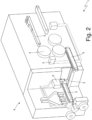
Figure 2 is a schematic and perspective view of a machine of the processing plant ofFigure 1 ; and -
Figure 3 is a schematic view of an electrical system of a machine of the processing plant ofFigure 1 . - In
Figure 1 ,number 1 denotes as a whole a processing plant for the production and packaging of cigarettes. - The
processing plant 1 comprises (at least) a production line formed by a plurality ofmachines 2 in which an output of aprevious machine 2 is connected to an input of a subsequent machine 2 (possibly with the interpretation of a compensating storage unit that allows to temporarily compensate the differences in speed between the machines 2). - In particular, the
processing plant 1 comprises, from top to bottom, amanufacturing machine 2a producing tobacco-based aromatic pieces (which constitutes the beginning of the production line), an assembly or filter-applyingmachine 2b (which receives the aromatic pieces from themanufacturing machine 2a and produces the cigarettes by assembling the aromatic pieces with the respective filter pieces), apackaging machine 2c (which receives the cigarettes from theassembly machine 2b and packages them into respective packets of cigarettes and is illustrated as an example inFigure 2 ), a cellophane-wrapping machine 2d (which receives the packets of cigarettes from thepackaging machine 2c and applies a corresponding transparent plastic coating to each packet of cigarettes 1), acartoning machine 2e (which receives the packets of cigarettes provided with the overwrap from the cellophane-wrapping machine 2d and packages them into respective cartons), and acartoning machine 2f (which constitutes the end of the production line and receives the cartons of packets of cigarettes from thecartoning machine 2e and packages them in corresponding boxes). - Between the assembly or filter-applying
machine 2b and thepackaging machine 2c a compensating storage unit 3 is provided, which allows to temporarily compensate the differences in speed between themachines - As better illustrated in
Figure 2 , eachmachine 2 comprises a frame 4 (base) that rests on the ground and supports a plurality of operating members 5 (which perform the actual processing of the materials leading to the final product); generally, the frame 4 has a vertical front wall on which most of theoperating members 5 are mounted. Eachmachine 2 also comprises a plurality of actuator devices 6 (schematically illustrated inFigure 1 ) that are carried by the frame 4, are coupled torespective operating members 5 and use electrical energy to perform operations (such as driving a movement, heating, and taking measurements). - As illustrated in
Figure 1 and similarly to themachines 2, the storage unit 3 also comprises operatingmembers 5 coupled torespective actuator devices 6. - As illustrated in
Figure 1 , theprocessing plant 1 comprises (at least) anelectrical line 7 that operates in alternating current, supplies all themachines 2 and the storage unit 3 and originates from a main electrical panel 8. - The
processing plant 1 comprises, furthermore, a plurality ofstorage devices 9, each of which is configured to store electrical energy, is coupled to a respective machine 2 (or to the respective storage unit 3) and is configured both to exchange electrical energy with theelectrical line 7 and to exchange electrical energy with theactuator devices 6 of the respective machine 2 (or of the respective storage unit 3). That is, eachstorage device 9 is configured to receive electrical energy from electrical line 7 (when there is an "excess" of electrical power in the electrical line 7) and to release electrical energy to the electrical line 7 (when there is a "shortage" of electrical power in the electrical line 7); furthermore, eachstorage device 9 is configured to release electrical energy to actuator devices 6 (whenactuator devices 6 operate as motors transforming electrical energy into mechanical energy) and to receive electrical energy from actuator devices 6 (whenactuator devices 6 operate, during braking, as generators transforming mechanical energy into electrical energy). - According to a possible embodiment, the
storage devices 9 are housed in the frames 4 of therespective machines 2 and of the storage unit 3 (namely, thestorage devices 9 are inside the frames 4 of therespective machines 2 and of the storage unit 3) and/or thestorage devices 9 are housed above the frames 4 of therespective machines 2 and of the storage unit 3 (namely, thestorage devices 9 are supported on the upper wall of the frames 4 of therespective machines 2 and of the storage unit 3); in this way, the presence of thestorage devices 9 does not increase the overall dimensions of themachines 2 and of the storage unit 3. Alternatively, thestorage devices 9 could be arranged next to the frames 4 of therespective machines 2 and of the storage unit 3. - According to a preferred embodiment, the
storage devices 9 use electrochemical cells; however, according to other embodiments, thestorage devices 9 can use other methods to store energy. - According to a possible embodiment illustrated in the attached figures, the
processing plant 1 comprises anelectrical line 10 that is independent of and separate from theelectrical line 7, operates in direct current and connects thestorage devices 9 to one another. Theelectrical line 10 allows thestorage devices 9 to exchange electrical energy in direct current with one another and therefore without having to go through a double conversion (from direct current to alternating current and therefore from alternating current to direct current). - The
electrical line 10 can be connected to asystem 11 for the generation of electrical energy using renewable sources, such as an electrical energy generation system using photovoltaic panels or an electrical energy generation system using wind generators. - As illustrated in
Figure 3 , each machine 2 (and also the storage unit 3) comprises anelectrical power system 12 that is connected to the alternating currentelectrical line 7 by means of the interposition of a bidirectional alternating-direct current converter 13 (namely, capable of both converting alternating current electrical energy into direct current electrical energy and converting direct current electrical energy into alternating current electrical energy). Thestorage device 9 is connected to the direct current side of the electrical power system 12 (namely, downstream of the converter 13) and is also connected to the alternating currentelectrical line 10. - As illustrated in
Figure 1 , acontrol unit 14 is also provided, which manages the flow of electrical energy into and out of the storage devices 9: typically thestorage devices 9 are activated to store electrical energy when there is an "excess" of electrical power and are activated to release electrical energy when there is a "shortage" of electrical power; the transfer of electrical energy can occur between (at least) onestorage device 9 and the alternating currentelectrical line 7, it can occur (alternatively or simultaneously) directly between (at least) twostorage devices 9 through the direct currentelectrical line 10 and it can occur (alternatively or simultaneously) between (at least) onestorage device 9 and thegeneration system 11 through the direct currentelectrical line 10. - By way of example, a machine 2 (and the storage unit 3) can have a nominal power of the order of 10-20 kW while a
storage device 9 can have a capacity to store electrical energy equal to at least one hour of operation of the respective machine 2 (or the respective storage unit 3) at the nominal power (and therefore corresponding to some hours of actual operation) and therefore can have a capacity to store electrical energy of the order of 10-50 kWh. - According to a possible embodiment, the
electrical line 7 and/or the electrical line 10 (if provided) can be made to run along the conveyors that connect the machines 2 (and the storage unit 3) to one another to transfer the products from aprevious machine 2 to thesubsequent machine 2. - In the embodiment illustrated in the attached figures, the
processing plant 1 has a single production line; according to other embodiments not illustrated, theprocessing plant 1 can comprise a plurality of production lines, each generally comprises its ownelectrical line 7 that originates from the main electrical panel 8. In the case of multiple production lines, the exchange of electrical energy between the production lines is normal since on average there is (often) at least one production line on hold (due to shift changes, maintenance or cleaning, brand changes, etc.). - The embodiments described here can be combined with one another without departing from the scope of protection of the present invention.
- The
processing plant 1 described above has numerous advantages. - First of all, the
processing plant 1 described above allows for a substantial increase in long-term energy efficiency since the capacity to store electrical energy is distributed exactly where the electrical energy is consumed (minimizing the transport and conversion of electrical energy which inevitably leads to energy loss). - Furthermore, the
processing plant 1 described above allows for a high capacity to store electrical energy with virtually no increase in actual size since the free space in the machines 2 (and in the storage unit 3) is used to house thestorage devices 9. - It is also important to note that each machine 2 (and the storage unit 3) incorporates a capacity to store a portion of the electrical energy required for its operation; therefore, when a machine 2 (or storage unit 3) is added or removed, the capacity to store electrical energy of the
processing plant 1 is consequently increased or decreased. - Finally, the
processing plant 1 described above is simple to implement. -
- 1 processing plant
- 2 machines
- 3 storage unit
- 4 frame
- 5 operating members
- 6 actuator devices
- 7 electrical line
- 8 main electrical panel
- 9 storage devices
- 10 electrical line
- 11 generation system
- 12 electrical power system
- 13 converter
- 14 control unit
Claims (15)
- A processing plant (1) for the production of articles and comprising:a plurality of machines (2), each comprises: a frame (4), a plurality of operating members (5) supported by the frame (4) and a plurality of actuator devices (6), which are supported by the frame (4), are coupled to respective operating members (5) and use electrical energy; andat least one first electrical line (7), which powers the machines (2);the processing plant (1) is characterised in that it comprises a plurality of storage devices (9), each of which is configured to store electrical energy, is coupled to a respective machine (2) and is configured both to exchange electrical energy with the first electrical line (7) and to exchange electrical energy with the actuator devices (6) of the respective machine (2).
- The processing plant (1) according to claim 1, wherein each storage device (9) is configured to receive electrical energy from the first electrical line (7) and to release electrical energy to the first electrical line (7).
- The processing plant (1) according to claim 1 or 2, wherein each storage device (9) is configured to release electrical energy to the actuator devices (6) and to receive electrical energy from the actuator devices (6).
- The processing plant (1) according to claim 1, 2 or 3, wherein the first electrical line (7) operates in alternating current.
- The processing plant (1) according to one of the claims from 1 to 4 and comprising a second electrical line (10), which is independent of and separate from the first electrical line (7) and connects the storage devices (9) to one another.
- The processing plant (1) according to claim 5, wherein the first electrical line (7) operates in alternating current and the second electrical line (10) operates in direct current.
- The processing plant (1) according to claim 5 or 6, wherein the second electrical line (10) can be connected to a system (11) for the generation of electrical energy by using renewable sources.
- The processing plant (1) according to claim 5, 6 or 7, wherein the second electrical line (10) is configured to allow the storage devices (9) to exchange electrical energy in direct current with one another.
- The processing plant (1) according to one of the claims from 5 to 8 and comprising a control unit (14) configured to manage the flow of electrical energy into and out of the storage devices (9) so that the storage devices (9) are activated to store electrical energy when there is an excess of electrical power and are activated to release electrical energy when there is a shortage of electrical power.
- The processing plant (1) according to claim 9, wherein the transfer of electrical energy can occur directly between at least two storage devices (9) through the second direct current electrical line (10).
- The processing plant (1) according to one of the claims from 5 to 10, wherein the second electrical line (10) runs along conveyors that connect the machines (2) to one another to transfer the products from a previous machine (2) to a subsequent machine (2).
- The processing plant (1) according to one of the claims from 1 to 10, wherein each storage device (9) has a capacity to store electrical energy equal to at least one hour of operation of the respective machine (2).
- The processing plant (1) according to one of the claims from 1 to 12, wherein at least one storage device (9) is housed in the frame (4) of the respective machine (2).
- The processing plant (1) according to one of the claims from 1 to 12, wherein at least one storage device (9) is housed above the frame (4) of the respective machine (2).
- The processing plant (1) according to one of the claims from 1 to 14, wherein the machines (2) are configured to process smoking articles.
Applications Claiming Priority (1)
| Application Number | Priority Date | Filing Date | Title |
|---|---|---|---|
| IT102023000022959A IT202300022959A1 (en) | 2023-10-31 | 2023-10-31 | PROCESSING PLANT FOR THE PRODUCTION OF ARTICLES AND PREFERABLY SMOKING ARTICLES |
Publications (1)
| Publication Number | Publication Date |
|---|---|
| EP4548784A1 true EP4548784A1 (en) | 2025-05-07 |
Family
ID=89983208
Family Applications (1)
| Application Number | Title | Priority Date | Filing Date |
|---|---|---|---|
| EP24209864.8A Pending EP4548784A1 (en) | 2023-10-31 | 2024-10-30 | Processing plant for the production of articles and, preferably, smoking articles |
Country Status (2)
| Country | Link |
|---|---|
| EP (1) | EP4548784A1 (en) |
| IT (1) | IT202300022959A1 (en) |
Families Citing this family (1)
| Publication number | Priority date | Publication date | Assignee | Title |
|---|---|---|---|---|
| IT202300022959A1 (en) | 2023-10-31 | 2025-05-01 | Gd Spa | PROCESSING PLANT FOR THE PRODUCTION OF ARTICLES AND PREFERABLY SMOKING ARTICLES |
Citations (19)
| Publication number | Priority date | Publication date | Assignee | Title |
|---|---|---|---|---|
| DE3519580C1 (en) | 1985-05-31 | 1987-03-05 | Bat Cigarettenfab Gmbh | Installation for manufacturing and packaging cigarettes |
| EP0261508A2 (en) | 1986-09-23 | 1988-03-30 | Focke & Co. (GmbH & Co.) | Device for transporting paper rolls to packaging machines |
| EP0347586A1 (en) | 1988-06-18 | 1989-12-27 | Focke & Co. (GmbH & Co.) | Device for transporting packaging material to a packaging machine |
| US5209247A (en) | 1990-06-07 | 1993-05-11 | B.A.T. Cigarettenfabriken Gmbh | System for manufacturing and packaging cigarettes |
| EP0882411A1 (en) | 1997-06-05 | 1998-12-09 | Focke & Co. (GmbH & Co.) | Device for the production and packing of cigarettes |
| EP1041006A2 (en) | 1999-03-29 | 2000-10-04 | Focke & Co. (GmbH & Co.) | Method and device for monitoring a (cigarette) making and packaging plant |
| EP1273541A2 (en) | 2001-02-27 | 2003-01-08 | Focke & Co. (GmbH & Co.) | Device for providing packaging machines with packaging material |
| WO2003074361A1 (en) | 2002-03-06 | 2003-09-12 | Focke & Co. (Gmbh & Co.) | (cigarette) production and packing unit and method and device for control thereof |
| EP1346651A1 (en) | 2002-03-21 | 2003-09-24 | G.D S.p.A. | A method and a device for managing the supply of wrapping and/or additional and/or auxiliary materials in a system for the manufacture of tobacco products |
| EP1587380A1 (en) | 2003-01-14 | 2005-10-26 | G.D S.p.A. | A method of managing a system for the manufacture of tobacco products |
| US20080289642A1 (en) | 2007-03-06 | 2008-11-27 | Luca Cerati | System for producing and packing articles |
| EP2004530A1 (en) | 2006-04-11 | 2008-12-24 | Focke & Co. (GmbH & Co. KG) | Device for handling bobbins of packaging material |
| EP2121449A1 (en) | 2007-01-23 | 2009-11-25 | British American Tobacco (Investments) Limited | Packaging machine and method |
| WO2018069882A1 (en) | 2016-10-14 | 2018-04-19 | G.D S.P.A. | Industrial plant |
| WO2021234751A1 (en) * | 2020-05-21 | 2021-11-25 | Danieli Automation S.P.A. | Electric power supply apparatus and method in an industrial plant |
| DE102021102557A1 (en) | 2021-02-04 | 2022-08-04 | Wittmann Battenfeld Gmbh | manufacturing plant |
| EP4039444A1 (en) | 2021-02-04 | 2022-08-10 | Wittmann Battenfeld GmbH | Method for operating a production facility |
| DE102022100526A1 (en) | 2022-01-11 | 2023-07-13 | Koenig & Bauer Ag | Production system, method for operating a production system and use of an energy store |
| IT202300022959A1 (en) | 2023-10-31 | 2025-05-01 | Gd Spa | PROCESSING PLANT FOR THE PRODUCTION OF ARTICLES AND PREFERABLY SMOKING ARTICLES |
-
2023
- 2023-10-31 IT IT102023000022959A patent/IT202300022959A1/en unknown
-
2024
- 2024-10-30 EP EP24209864.8A patent/EP4548784A1/en active Pending
Patent Citations (19)
| Publication number | Priority date | Publication date | Assignee | Title |
|---|---|---|---|---|
| DE3519580C1 (en) | 1985-05-31 | 1987-03-05 | Bat Cigarettenfab Gmbh | Installation for manufacturing and packaging cigarettes |
| EP0261508A2 (en) | 1986-09-23 | 1988-03-30 | Focke & Co. (GmbH & Co.) | Device for transporting paper rolls to packaging machines |
| EP0347586A1 (en) | 1988-06-18 | 1989-12-27 | Focke & Co. (GmbH & Co.) | Device for transporting packaging material to a packaging machine |
| US5209247A (en) | 1990-06-07 | 1993-05-11 | B.A.T. Cigarettenfabriken Gmbh | System for manufacturing and packaging cigarettes |
| EP0882411A1 (en) | 1997-06-05 | 1998-12-09 | Focke & Co. (GmbH & Co.) | Device for the production and packing of cigarettes |
| EP1041006A2 (en) | 1999-03-29 | 2000-10-04 | Focke & Co. (GmbH & Co.) | Method and device for monitoring a (cigarette) making and packaging plant |
| EP1273541A2 (en) | 2001-02-27 | 2003-01-08 | Focke & Co. (GmbH & Co.) | Device for providing packaging machines with packaging material |
| WO2003074361A1 (en) | 2002-03-06 | 2003-09-12 | Focke & Co. (Gmbh & Co.) | (cigarette) production and packing unit and method and device for control thereof |
| EP1346651A1 (en) | 2002-03-21 | 2003-09-24 | G.D S.p.A. | A method and a device for managing the supply of wrapping and/or additional and/or auxiliary materials in a system for the manufacture of tobacco products |
| EP1587380A1 (en) | 2003-01-14 | 2005-10-26 | G.D S.p.A. | A method of managing a system for the manufacture of tobacco products |
| EP2004530A1 (en) | 2006-04-11 | 2008-12-24 | Focke & Co. (GmbH & Co. KG) | Device for handling bobbins of packaging material |
| EP2121449A1 (en) | 2007-01-23 | 2009-11-25 | British American Tobacco (Investments) Limited | Packaging machine and method |
| US20080289642A1 (en) | 2007-03-06 | 2008-11-27 | Luca Cerati | System for producing and packing articles |
| WO2018069882A1 (en) | 2016-10-14 | 2018-04-19 | G.D S.P.A. | Industrial plant |
| WO2021234751A1 (en) * | 2020-05-21 | 2021-11-25 | Danieli Automation S.P.A. | Electric power supply apparatus and method in an industrial plant |
| DE102021102557A1 (en) | 2021-02-04 | 2022-08-04 | Wittmann Battenfeld Gmbh | manufacturing plant |
| EP4039444A1 (en) | 2021-02-04 | 2022-08-10 | Wittmann Battenfeld GmbH | Method for operating a production facility |
| DE102022100526A1 (en) | 2022-01-11 | 2023-07-13 | Koenig & Bauer Ag | Production system, method for operating a production system and use of an energy store |
| IT202300022959A1 (en) | 2023-10-31 | 2025-05-01 | Gd Spa | PROCESSING PLANT FOR THE PRODUCTION OF ARTICLES AND PREFERABLY SMOKING ARTICLES |
Also Published As
| Publication number | Publication date |
|---|---|
| IT202300022959A1 (en) | 2025-05-01 |
Similar Documents
| Publication | Publication Date | Title |
|---|---|---|
| CA2906590C (en) | Interface for renewable energy system | |
| EP4548784A1 (en) | Processing plant for the production of articles and, preferably, smoking articles | |
| EP3359807B1 (en) | Apparatus and method of generating energy from renewable energy sources | |
| US8427005B1 (en) | Generator power module | |
| US20140049229A1 (en) | Power generation unit driver, power generation unit and energy output equipment in power grid | |
| US8247923B2 (en) | Method for operating a photovoltaic system and photovoltaic system for carrying out the method | |
| WO2013175612A1 (en) | Power supply system | |
| WO2007133940A3 (en) | Fuel cell assembly using multiple fuel cell stacks and control method therefor | |
| WO2017056114A1 (en) | Wind-solar hybrid power generation system and method | |
| KR20120080155A (en) | Photovoltaic and wind power combined electric generator | |
| KR100444616B1 (en) | A power generation system by combinded for utilizing solar energy/wind force | |
| EP2539266B1 (en) | Power supply system for rack and pinion lifts and method for powering these | |
| CN204206064U (en) | A kind of field modularization energy supplyystem | |
| ITPI20110142A1 (en) | ENERGY TRANSFORMATION EQUIPMENT PRODUCED BY RENEWABLE SOURCES AND RELATIVE MANAGEMENT METHOD | |
| EP2870635A1 (en) | An ac solar panel system | |
| US20100187821A1 (en) | Sustainable process of clean energy generation and distribution | |
| WO2010013731A1 (en) | Power distribution system | |
| CN202108671U (en) | Wind power generation mechanism and electro-car equipped with the same | |
| WO2014068591A1 (en) | Integrated wind and solar power system | |
| JP2013214644A (en) | Photovoltaic power generation system | |
| RU191112U1 (en) | Device for automatically connecting and switching load power sources for hybrid power plants based on photovoltaic modules, batteries and diesel generator set (DGU) | |
| EP3526879B1 (en) | Industrial plant | |
| EP3179595B1 (en) | Method for operating a solar power plant | |
| KR20140002754U (en) | Tower of wind turbine | |
| CN102619699A (en) | Wind generating set |
Legal Events
| Date | Code | Title | Description |
|---|---|---|---|
| PUAI | Public reference made under article 153(3) epc to a published international application that has entered the european phase |
Free format text: ORIGINAL CODE: 0009012 |
|
| STAA | Information on the status of an ep patent application or granted ep patent |
Free format text: STATUS: THE APPLICATION HAS BEEN PUBLISHED |
|
| AK | Designated contracting states |
Kind code of ref document: A1 Designated state(s): AL AT BE BG CH CY CZ DE DK EE ES FI FR GB GR HR HU IE IS IT LI LT LU LV MC ME MK MT NL NO PL PT RO RS SE SI SK SM TR |
|
| TPAC | Observations filed by third parties |
Free format text: ORIGINAL CODE: EPIDOSNTIPA |
|
| STAA | Information on the status of an ep patent application or granted ep patent |
Free format text: STATUS: THE APPLICATION IS DEEMED TO BE WITHDRAWN |