EP4546246A2 - Überwachung des werkzeugkalibrierungsstatus in automatisierten werkzeugsteuerungssystemen - Google Patents
Überwachung des werkzeugkalibrierungsstatus in automatisierten werkzeugsteuerungssystemen Download PDFInfo
- Publication number
- EP4546246A2 EP4546246A2 EP25151736.3A EP25151736A EP4546246A2 EP 4546246 A2 EP4546246 A2 EP 4546246A2 EP 25151736 A EP25151736 A EP 25151736A EP 4546246 A2 EP4546246 A2 EP 4546246A2
- Authority
- EP
- European Patent Office
- Prior art keywords
- calibration
- calibrated
- inventory item
- automated
- monitoring system
- Prior art date
- Legal status (The legal status is an assumption and is not a legal conclusion. Google has not performed a legal analysis and makes no representation as to the accuracy of the status listed.)
- Pending
Links
Images


Classifications
-
- G—PHYSICS
- G01—MEASURING; TESTING
- G01L—MEASURING FORCE, STRESS, TORQUE, WORK, MECHANICAL POWER, MECHANICAL EFFICIENCY, OR FLUID PRESSURE
- G01L5/00—Apparatus for, or methods of, measuring force, work, mechanical power, or torque, specially adapted for specific purposes
- G01L5/0061—Force sensors associated with industrial machines or actuators
- G01L5/0066—Calibration arrangements
-
- B—PERFORMING OPERATIONS; TRANSPORTING
- B25—HAND TOOLS; PORTABLE POWER-DRIVEN TOOLS; MANIPULATORS
- B25B—TOOLS OR BENCH DEVICES NOT OTHERWISE PROVIDED FOR, FOR FASTENING, CONNECTING, DISENGAGING, OR HOLDING
- B25B13/00—Spanners; Wrenches
- B25B13/48—Spanners; Wrenches for special purposes
-
- B—PERFORMING OPERATIONS; TRANSPORTING
- B25—HAND TOOLS; PORTABLE POWER-DRIVEN TOOLS; MANIPULATORS
- B25B—TOOLS OR BENCH DEVICES NOT OTHERWISE PROVIDED FOR, FOR FASTENING, CONNECTING, DISENGAGING, OR HOLDING
- B25B23/00—Details of, or accessories for, spanners, wrenches, screwdrivers
-
- B—PERFORMING OPERATIONS; TRANSPORTING
- B25—HAND TOOLS; PORTABLE POWER-DRIVEN TOOLS; MANIPULATORS
- B25B—TOOLS OR BENCH DEVICES NOT OTHERWISE PROVIDED FOR, FOR FASTENING, CONNECTING, DISENGAGING, OR HOLDING
- B25B23/00—Details of, or accessories for, spanners, wrenches, screwdrivers
- B25B23/14—Arrangement of torque limiters or torque indicators in wrenches or screwdrivers
-
- B—PERFORMING OPERATIONS; TRANSPORTING
- B25—HAND TOOLS; PORTABLE POWER-DRIVEN TOOLS; MANIPULATORS
- B25B—TOOLS OR BENCH DEVICES NOT OTHERWISE PROVIDED FOR, FOR FASTENING, CONNECTING, DISENGAGING, OR HOLDING
- B25B23/00—Details of, or accessories for, spanners, wrenches, screwdrivers
- B25B23/14—Arrangement of torque limiters or torque indicators in wrenches or screwdrivers
- B25B23/142—Arrangement of torque limiters or torque indicators in wrenches or screwdrivers specially adapted for hand operated wrenches or screwdrivers
- B25B23/1422—Arrangement of torque limiters or torque indicators in wrenches or screwdrivers specially adapted for hand operated wrenches or screwdrivers torque indicators or adjustable torque limiters
- B25B23/1425—Arrangement of torque limiters or torque indicators in wrenches or screwdrivers specially adapted for hand operated wrenches or screwdrivers torque indicators or adjustable torque limiters by electrical means
-
- B—PERFORMING OPERATIONS; TRANSPORTING
- B25—HAND TOOLS; PORTABLE POWER-DRIVEN TOOLS; MANIPULATORS
- B25H—WORKSHOP EQUIPMENT, e.g. FOR MARKING-OUT WORK; STORAGE MEANS FOR WORKSHOPS
- B25H3/00—Storage means or arrangements for workshops facilitating access to, or handling of, work tools or instruments
- B25H3/02—Boxes
- B25H3/021—Boxes comprising a number of connected storage elements
- B25H3/023—Boxes comprising a number of connected storage elements movable relative to one another for access to their interiors
- B25H3/028—Boxes comprising a number of connected storage elements movable relative to one another for access to their interiors by sliding extraction from within a common frame
-
- G—PHYSICS
- G01—MEASURING; TESTING
- G01L—MEASURING FORCE, STRESS, TORQUE, WORK, MECHANICAL POWER, MECHANICAL EFFICIENCY, OR FLUID PRESSURE
- G01L25/00—Testing or calibrating of apparatus for measuring force, torque, work, mechanical power, or mechanical efficiency
- G01L25/003—Testing or calibrating of apparatus for measuring force, torque, work, mechanical power, or mechanical efficiency for measuring torque
-
- G—PHYSICS
- G06—COMPUTING OR CALCULATING; COUNTING
- G06Q—INFORMATION AND COMMUNICATION TECHNOLOGY [ICT] SPECIALLY ADAPTED FOR ADMINISTRATIVE, COMMERCIAL, FINANCIAL, MANAGERIAL OR SUPERVISORY PURPOSES; SYSTEMS OR METHODS SPECIALLY ADAPTED FOR ADMINISTRATIVE, COMMERCIAL, FINANCIAL, MANAGERIAL OR SUPERVISORY PURPOSES, NOT OTHERWISE PROVIDED FOR
- G06Q10/00—Administration; Management
- G06Q10/08—Logistics, e.g. warehousing, loading or distribution; Inventory or stock management
- G06Q10/087—Inventory or stock management, e.g. order filling, procurement or balancing against orders
-
- G—PHYSICS
- G06—COMPUTING OR CALCULATING; COUNTING
- G06Q—INFORMATION AND COMMUNICATION TECHNOLOGY [ICT] SPECIALLY ADAPTED FOR ADMINISTRATIVE, COMMERCIAL, FINANCIAL, MANAGERIAL OR SUPERVISORY PURPOSES; SYSTEMS OR METHODS SPECIALLY ADAPTED FOR ADMINISTRATIVE, COMMERCIAL, FINANCIAL, MANAGERIAL OR SUPERVISORY PURPOSES, NOT OTHERWISE PROVIDED FOR
- G06Q50/00—Information and communication technology [ICT] specially adapted for implementation of business processes of specific business sectors, e.g. utilities or tourism
- G06Q50/04—Manufacturing
-
- Y—GENERAL TAGGING OF NEW TECHNOLOGICAL DEVELOPMENTS; GENERAL TAGGING OF CROSS-SECTIONAL TECHNOLOGIES SPANNING OVER SEVERAL SECTIONS OF THE IPC; TECHNICAL SUBJECTS COVERED BY FORMER USPC CROSS-REFERENCE ART COLLECTIONS [XRACs] AND DIGESTS
- Y02—TECHNOLOGIES OR APPLICATIONS FOR MITIGATION OR ADAPTATION AGAINST CLIMATE CHANGE
- Y02P—CLIMATE CHANGE MITIGATION TECHNOLOGIES IN THE PRODUCTION OR PROCESSING OF GOODS
- Y02P90/00—Enabling technologies with a potential contribution to greenhouse gas [GHG] emissions mitigation
- Y02P90/30—Computing systems specially adapted for manufacturing
Definitions
- the present subject matter relates to techniques and equipment for monitoring of tool calibration statuses of tools in automated tool control systems.
- Torque wrenches have long been used in industry to accurately tighten fasteners in assembly, maintenance and repair operations. This is especially true in the aerospace industry, where use of torque wrenches is required and tightly controlled.
- torque wrenches are required to be calibrated by users on a regular basis.
- the calibration involves the user performing a torque test of a tool, the user recording of the torque test result in a log to create a record of tool calibration for future reference, and the user determining whether the tool should be used depending on the result of the torque test.
- the procedures used for tool calibration and recording are generally performed by the user manually, and both calibration and recording is therefore subject to human error. For example, if a torque test result is incorrectly recorded or an incorrect target range is used, a torque wrench having an incorrect calibration value may continue to be used in torqueing and tightening of fasteners despite the tool applying an unknown and potentially incorrect torque load on the fasteners.
- each fastener joint torqued by the out-of-calibration wrench e.g., every fastener joint torqued since the wrench's last accurately recorded calibration operation
- an automated calibration monitoring system includes a plurality of storage locations configured to store inventory items including a calibrated inventory item, a database, and a processor.
- the database stores information on inventory items, including the calibrated inventory item, associated with the automated calibration monitoring system and configured for storage in the plurality of storage locations of the automated calibration monitoring system.
- the database further stores a calibration parameter value for the calibrated inventory item.
- the processor is configured to, upon the calibrated inventory item being issued from or returned to the automated calibration monitoring system, compare a calibration measurement of the calibrated inventory item with the calibration parameter value for the calibrated inventory item.
- the processor may selectively authorize the issue or return of the calibrated inventory item according to a result of the comparison.
- the automated calibration monitoring system may further include a calibration measurement device communicatively connected to the processor and configured to perform a calibration measurement of the calibrated inventory item to obtain the calibration measurement.
- the calibration measurement device may communicate the obtained calibration measurement to the processor.
- the calibrated inventory item may be a torque wrench, and the calibration measurement instrument may be a torque tester.
- the processor may be further configured to, upon the calibrated inventory item being issued from or returned to the automated calibration monitoring system, transmit a calibration target value for the calibrated inventory item to the calibration measurement device.
- the processor may receive the obtained calibration measurement from the calibration measurement device after the transmission of the calibration target value.
- the calibration parameter value stored in the database may include an acceptable range of calibration parameter values stored in the database, and the processor may selectively authorize the issue or return of the calibrated inventory item when the calibration measurement is within the acceptable range of calibration parameter values.
- the automated calibration monitoring system may further include a sensing device configured to sense information used by the processor to determine the presence or absence of inventory items in the plurality of storage locations.
- the processor may be configured to determine presence of the calibrated inventory item in a storage location of the plurality of storage locations based on the information sensed by the sensing device.
- the sensing device may include an image sensor configured to capture images of storage locations of the automated calibration monitoring system, and the processor may be configured to determine presence of the calibrated inventory item by determining whether the calibrated inventory item is present in an image captured by the image sensor.
- Each inventory item associated with the automated calibration monitoring system may have a tag uniquely identifying the inventory item, and the processor may be configured to uniquely identify an inventory item present in a storage location of the plurality of storage locations by recognizing the tag uniquely identifying the inventory item in the information sensed by the sensing device.
- Each inventory item associated with the automated inventory control system may have a radio frequency identification (RFID) tag uniquely identifying the inventory item, and the automated inventory control system may further include an RFID sensor configured to read RFID tags of inventory items located within the plurality of storage locations.
- RFID radio frequency identification
- the database may store records of work orders associated with previous issuances of the calibrated inventory item, and the database may store records of previous calibration measurements of the calibrated inventory item.
- the processor may be configured to, upon determining that the compared calibration measurement of the calibrated inventory item is inconsistent with the calibration parameter value for the calibrated inventory item, retrieve from the database all records of work orders associated with the calibrated inventory item and corresponding to issuances of the calibrated inventory item following the last stored record of a previous calibration measurement of the calibrated inventory item.
- a method for automated monitoring of calibration of inventory items in an automated calibration monitoring system includes identifying, using a sensor of the automated calibration monitoring system configured to sense presence or absence of inventory items, a calibrated inventory item subject to monitoring of calibration.
- a calibration parameter value for the identified calibrated inventory item is retrieved from a database communicatively connected to the automated calibration monitoring system and storing calibration parameter values for each of a plurality of inventory items.
- a calibration status of the calibrated identified inventory item is determined based on a comparison of a calibration measurement of the calibrated inventory item with the retrieved calibration parameter value for the calibrated inventory item.
- the automated calibration monitoring system may selectively authorize the issue or return of the calibrated inventory item from a storage location of the automated calibration monitoring system according to a result of the determination.
- the method may further include, prior to the determining, receiving, from a calibration measurement device communicatively connected to the automated calibration monitoring system and configured to perform a calibration measurement of the calibrated inventory item, the calibration measurement of the calibrated inventory item.
- the calibrated inventory item may be a torque wrench, and the calibration measurement instrument may be a torque tester.
- the method may further include transmitting a calibration target value for the calibrated inventory item to the calibration measurement device, where the automated calibration monitoring system receives the calibration measurement from the calibration measurement device after the transmission of the calibration target value.
- Each inventory item associated with the automated calibration monitoring system may have a tag uniquely identifying the inventory item, and the automated calibration monitoring system may be configured to uniquely identify the calibrated inventory item by recognizing the tag uniquely identifying the calibrated inventory item in information sensed by the sensor.
- Each inventory item associated with the automated inventory control system may have a visible tag uniquely identifying the inventory item, and the automated inventory control system may identify the calibrated inventory item by identifying the visible tag of the calibrated inventory item in an image captured by an image sensing device of the automated inventory control system.
- Each inventory item associated with the automated inventory control system may have a radio frequency identification (RFID) tag uniquely identifying the inventory item, and the automated inventory control system may identify the calibrated inventory item by reading the RFID tag of the calibrated inventory item.
- RFID radio frequency identification
- the various systems and methods disclosed herein relate to the automated monitoring of tool calibration status in automated tool control systems.
- the automated monitoring of tool calibration status is performed using a calibration measurement instrument or device such as an electronic torque tester.
- the calibration measurement device is communicatively connected with an automated calibration monitoring device, such as an automated inventory control system, which stores calibrated devices such as calibrated torque wrenches and other calibrated tools and monitors the tools issuances/removals from and returns to the system.
- the calibration measurement device additionally communicates with a calibration database storing calibration values for the tools.
- the automated calibration monitoring device is configured to uniquely identify tools (and other objects, reference generally as inventory items) stored therein, and to selectively allow issue of individual tools/objects/inventory-items from storage and/or return of the tools/objects into storage based on the result of a calibration measurement such as a torque measurement of the tools/objects.
- the calibration measurement device such as the electronic torque tester, receives a unique identification of a tool/object from the automated calibration monitoring device, retrieves a calibration value for the identified tool/object from the calibration database, and performs a calibration measurement based on the retrieved calibration value.
- the automated calibration monitoring device determines whether the calibration measurement is within an acceptable range for the tool/object, and selectively allows issue of the tool/object from the automated calibration monitoring device and/or return of the tool/object to the automated calibration monitoring device based on the result of the determination (e.g., based on determining that the tool/object is accurately calibrated).
- the tool/object is a calibrated torque wrench that is designed to apply a pre-calibrated maximum torque value stored in the calibration database.
- the automated calibration monitoring device uniquely identifies the torque wrench on the basis of a tag or identifier applied thereto, and detects that a user has removed the torque wrench from the automated calibration monitoring device. Based on the detection, the automated calibration monitoring device prompts a user to test a current calibration of the torque wrench and, for measurement purposes, communicates the calibration value for the torque wrench to an electronic torque tester. Upon a torque measurement being performed on the torque wrench based on the communicated calibration value, the automated calibration monitoring device determines whether the measurement falls within an acceptable range surrounding the calibration value and allows issue of the torque wrench from the automated calibration monitoring device. However, if the measurement falls outside of the acceptable range surrounding the calibration value, the automated calibration monitoring device alerts the user and instructs the user to return the torque wrench to the automated calibration monitoring device for recalibration.
- the tools or other inventory objects stored in the automated calibration monitoring device are individually identifiable by the automated calibration monitoring device.
- the tools/objects can have tags or other identifiers applied thereto to enable tools/objects that visually appear similar to each other (e.g., two visually identical torque wrenches) to be uniquely/individually identified.
- the tags or identifiers may encode a tool's serial number or other unique identifier, and enable the calibration status of each tool/object to be individually monitored and recorded in association with the tool/object's unique identifier.
- each tool/object can then be monitored upon each issuance or return of the tool/object from/to the automated calibration monitoring device, and/or on a pre-scheduled basis, on a periodic basis based on a number of issues/returns since a previous calibration measurements, or the like.
- Each tool/object's issuance and/or return can further be associated with a work order or job order, and the tool/object's most recently recorded calibration measurement value can be associated with each operation (e.g., tightening of each bolt or fastener) performed as part of the work order or job order.
- each operation e.g., tightening of each bolt or fastener
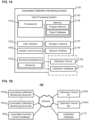
- FIG. 1A is a block diagram showing components of an automated calibration monitoring device 100, such as the automated tool control system 200 functioning as a calibration monitoring device illustratively shown in FIG. 2A .
- the automated calibration monitoring device 100 may be used as part of an automated calibration monitoring system 190 such as that shown in the block diagram of FIG. 1B .
- the automated calibration monitoring device 100 includes storage locations 130 for storing objects/tools therein, and one or more sensing subsystem(s) 150 for determining the inventory status of objects/tools in the automated calibration monitoring device 100. Additionally, the automated calibration monitoring device 100 can include one or more of a user interface 105, an access control device 106, and a network interface 108. The automated calibration monitoring device 100 can also include a direct wired or wireless communication interface, such as a Bluetooth communication interface for communicating directly with a calibration device 160 or other automated calibration monitoring device.
- a direct wired or wireless communication interface such as a Bluetooth communication interface for communicating directly with a calibration device 160 or other automated calibration monitoring device.
- the storage locations 130 are provided within a body of the automated calibration monitoring device 100 within which tools/objects can be securely stored.
- the storage locations 130 can include one or more storage drawers (see, e.g., 230 in FIGS. 2A-2C ), shelves, cabinet doors, or the like.
- the user interface 105 may include one or more user input/output devices, such as a display (e.g., a touch-sensitive display), a keyboard, a mouse or touchpad, a speaker and/or microphone, or the like.
- the user interface 105 can be used to output information to a user of the device 100 (e.g., via display) and/or receive input and selections from the user (e.g., via a touch-sensitive input device).
- the access control device 106 may include one or more of a card reader (e.g., identification card reader), an iris scanner, or the like for receiving identification information from a user seeking access to the device 100.
- the access control device 106 can also include an alarm used for issuing alerts in response to detecting unauthorized access attempts, and a locking mechanism used to securely lock or block access to the storage locations 130 when no authorized user is logged into the device 100.
- the network interface 108 enables the automated calibration monitoring device 100 to communicate across one or more wired or wireless networks with other networked automated calibration monitoring devices (e.g., 100a-100n in FIG. 1B ), calibration device(s) (e.g., 160a-160m in FIG. 1B ), a calibration database 170, an automated inventory control database (e.g., 180 in FIG. 1B ), and/or other components of a networked automated calibration monitoring system 190 (see FIG. 1B ) that may be used to monitor the calibration of and inventory statuses of objects/tools across multiple automated calibration monitoring devices 100.
- networked automated calibration monitoring devices e.g., 100a-100n in FIG. 1B
- calibration device(s) e.g., 160a-160m in FIG. 1B
- a calibration database 170 e.g., an automated inventory control database
- a networked automated calibration monitoring system 190 see FIG. 1B
- the automated calibration monitoring device 100 is further configured to include or interface with a calibration device 160 (e.g., a calibration measurement device) and a calibration database 170.
- a calibration device 160 e.g., a calibration measurement device
- a calibration database 170 can be located within the automated calibration monitoring device 100 and can interface directly with the automated calibration monitoring device 100.
- the calibration device 160 and calibration database 170 can be located separate from the automated calibration monitoring device 160 and be communicatively connected to the automated calibration monitoring device 100 through a wired or wireless communication link and/or network (see, e.g., FIG. 1B ).
- the calibration device 160 may be used to measure a calibration status of a tool/object.
- the calibration device 160 can take the form of a torque tester or other torque measurement device configured to measure an output torque of a torque wrench.
- the calibration device 160 may be an electronic torque tester such as a torque tester including a piezoelectric torque transducer mounted in a frame and operative to operative to take torque readings and communicate the torque readings to the automated calibration monitoring device 100.
- the calibration device 160 optionally includes a display for display of the calibration measurements (e.g., torque readings) to users.
- the torque transducers in a calibration device 160 can be sized for measuring various applied torque loads.
- the calibration device 160 can be communicatively connected to the automated calibration monitoring device 100 or to a network to enable calibration measurement data to be transferred through wired or wireless communication interfaces and links
- the automated calibration monitoring device 100 can be used with other types of calibrated tools.
- the calibrated torque wrench may have an associated torque calibration value and/or angle calibration value for measurement by the calibration device 160.
- the calibrated tool may be a torque screwdriver having an associated torque calibration value and/or angle calibration value for measurement by the calibration device 160.
- a precision caliper may be used for precise distance/width/length measurements and may have its calibration measured and monitored using a calibration device 160 such as a precision measurement tool.
- a digital multimeter used for electrical measurements may be used for precise voltage, current, and resistance measurements and may have its calibration measured and monitored using a calibration device 160 such as a precision voltage/current/resistance measurer.
- the automated calibration monitoring device 100 further includes a data processing system 140, such as a computer, for controlling the functioning of the automated calibration monitoring device 100.
- the data processing system 140 processes sensing data received from sensing subsystem(s) 150 and determines inventory conditions of objects/tools and storage locations 130 based on the sensing data.
- the data processing system 140 processes images captured by a camera or other image sensing device and/or signals received by RFID sensors.
- the data processing system 140 includes one or more processors 142 (e.g., micro-processors) and memory 144 (including non-transitory memory, read only memory (ROM), random access memory (RAM), or the like).
- the memory 144 includes a program memory storing program instructions for causing the automated calibration monitoring device 100 to perform calibration monitoring and inventory control functions such as those described herein.
- the memory 144 also includes a database of object/tool information, which may include object/tool identifiers, object/tool images, object/tool tag information (e.g., for RFID or bar-code tags), object/tool inventory status and calibration status information, and the like.
- the program instructions further cause the device 100 to communicate with calibration device(s) 160 to obtain calibration measurements for objects/tools as described in further detail below.
- the components of the automated calibration monitoring device 100 of FIG. 1A are communicatively connected with each other, for example via a communication bus or other communication links.
- the data processing system 140 functions as a central processing unit (CPU) for executing program instructions, such as program instructions stored in a non-transitory machine readable storage medium (e.g., memory 144), for controlling the operation of the automated calibration monitoring device 100.
- the sensing subsystem(s) 150 and calibration device(s) 160 can include microprocessors operative to execute program instructions and perform functions relating to sensing/monitoring/measurement operations.
- the automated calibration monitoring device 100 can also be in communication via network interface 108 with wired and/or wireless local area and/or wide area networks (e.g., the Internet).
- the monitoring system 190 may include multiple automated calibration monitoring devices 100a-100n.
- Each automated calibration monitoring device may be in communication with one or more other automated calibration monitoring device(s) (e.g., 100n) and/or other elements forming an automated calibration monitoring system 190 such as calibration device(s) 160a-160m, the calibration database 170 (including, e.g., a calibration server storing the calibration database), and an automated inventory control database 180 (including, e.g., an inventory control server storing the inventory control database).
- the automated calibration monitoring device 100a may communicate with the other systems and/or servers across the network(s), and may exchange information on calibration measurements, inventory conditions, stored objects/tools, and operation data with those systems and/or servers.
- the automated calibration monitoring device 100a may alternatively or additionally communicate directly with some of the components of the system 190, for example through direct wired or wireless (e.g., Bluetooth) links with calibration devices 160a-160m or other components.
- the networked calibration monitoring system shown in FIG. 1B can use the Windows Communication Foundation (WCF) or similar technology to create a "network service" used to enable communications between devices and databases.
- WCF Windows Communication Foundation
- communications between devices and databases can use a common protocol and information format, such as protocols and formats compatible with WCF, to store and enable easy exchange of inventory, calibration, and other information between devices and servers.
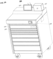
- the automated calibration monitoring device 100 can take the form of an automated tool control system 200, such as that shown in FIG. 2A , that provides for the monitoring of tool calibration status (e.g., torque calibration status).
- the automated tool control system 200 as depicted takes the form of an automated tool control (ATC) toolbox, but may more generally take the form of an ATC locker, an ATC tool crib, or the like.
- the automated tool control system 200 is connected via a direct wired or direct wireless communication link or via a wired or wireless network to a torque calibration device 207 such as a piezoelectric torque testing/measurement device functioning as a calibration device 160.
- the torque calibration device 207 may be mounted on the automated tool control system 200, as illustratively shown in FIG. 2A , or provided separately or remotely therefrom.
- the automated tool control system 200 includes a database (e.g., object database stored in memory 144 and/or calibration database 170 and inventory control database 180) for storage and retrieval of tool related data, including torque tool usage and calibration data.
- the database may be local to the automated tool control system 200 (see, e.g., FIG. 1A ) or communicatively connected thereto through a network interface (see, e.g., FIGS. 1A and 1B ).
- the automated tool control system 200 is an example of a highly automated inventory control system that utilizes one or more sensing technologies to identify inventory conditions of tools and other objects in the storage unit.
- the term inventory condition as used throughout this disclosure means information relating to an existence/presence or non-existence/absence condition of objects in the storage system, and/or information on the issuance and return of objects from/to the tool control system 200 and storage locations 130 thereof.
- the inventory conditions are determined using machine imaging, radio frequency (RF) sensing, and/or other sensing methodologies used by the tool control system 200 to identify inventory conditions of objects configured for storage therein.
- RF radio frequency
- the tool control system 200 includes a user interface 205, an access control device 206, such as a card reader, for verifying identity and authorization levels of a user intending to tool control system 200, and multiple tool storage drawers 230 for storing tools.
- the storage system may include shelves, compartments, trays, containers, or other object storage devices from which tools or objects are issued and/or returned, or which contain the storage device from which the objects are issued and/or returned.
- the storage system includes storage hooks, hangers, tool boxes with drawers, lockers, cabinets with shelves and/or doors, safes, boxes, closets, vending machines, barrels, crates, and other material storage means.
- User interface 205 is an input and/or output device of tool control system 200, configured to display information to a user including tool calibration and measurement information.
- Access control device 206 is used to limit or allow access of users to the tool storage drawers 230.
- Access control device 206 through the use of one or more electronically controlled locking devices or mechanisms, keeps some or all storage drawers 230 locked in a closed position until access control device 206 authenticates and authorizes a user for access to the storage system.
- the access control device 206 further includes a processor and software to electronically identify a user requesting access to the secure area or object storage device and determine the level of access which should be granted or denied to the identified user.
- access control device 206 determines that a user is authorized to access control system 200, it unlocks some or all storage drawers 230, depending on the user's authorization level, allowing the user to remove or replace tools.
- the access control device 206 may identify predetermined authorized access levels to the system (e.g., a full access level providing access to all drawers 230, a partial access level providing access only to particular drawer(s) 230, or the like), and allow or deny physical access by the user to the three dimensional space or object storage devices based on those predetermined authorized levels of access.
- the access control device 206 may also be used to deny a user access to drawers 230 storing tools that are identified as being out of calibration, and/or to deny a user access to stored tools until a tool identified as being out-of-calibration is returned to an appropriate storage location.
- Tool control system 200 includes one or more different sensing subsystems.
- the tool storage system 200 includes an image-based sensing subsystem configured to capture images of contents or storage locations of the system using one or more cameras.
- the image sensing subsystem is further configured to process the images to identify tools/objects present therein or absent therefrom, and to determine inventory conditions based on the processed image data.
- the image sensing subsystem may include one or more lens-based cameras, CCD cameras, CMOS cameras, video cameras, or other types of devices that captures images.
- the tool control system 200 can additionally or alternatively include an RFID sensing subsystem including one or more RFID antennas, RFID transceivers, and RFID processors.
- the RFID sensing subsystem is configured to emit RF sensing signals through the RFID transceivers and antennas when an RF-based scan of the inventory control system 200 is performed, receive RFID signals sensed by the RFID antennas and transceivers from RFID tags mounted on or incorporated in tools or other inventory items in response to the emitting the RF sensing signals, and process the received RFID signals to identify individual tools or inventory items.
- the received RFID signals may be processed to extract tag identification data included in the returned RFID signals, and to identify individual tools or inventory items located in the tool control system 200 based on an association between tag identification data and tool data stored by the system.
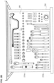
- FIG. 2B shows a detailed view of one illustrative drawer 230 of the control system 200 in an open position.
- the storage drawer 230 includes a foam base 280 having a plurality of storage locations, such as tool cutouts 281, for storing tools. Each cutout is specifically contoured and shaped for fittingly receiving a tool with a corresponding shape. Tools may be secured in each storage location by using hooks, Velcro, latches, pressure from the foam, etc.
- each storage drawer 230 includes multiple storage locations for storing various types of tools.
- a storage location is a location in a storage system for storing or securing objects.
- each tool has a specific pre-designated storage location in the tool storage system.
- multiple storage locations may have similar (or identical) shapes, and several similarly shaped tools may thus be placed in any of the multiple storage locations.
- one or more tools in the drawer 230 may have unique identifiers such as identification tags 231a and 231b mounted or attached thereon or therein.
- the identification tags may be RFID tags, bar-code tags, or the like.
- the RFID tags may be placed on a surface of the tools and may thus be visible to users, such as tag 231a, or the RFID tags may be placed within the tool or may otherwise not be visible to users, such as tag 231b.
- bar-code tags would be placed on a surface of the tools, such as tag 231a.
- tags placed on tools may be visible and each tag may encode the identifier unique to the tool it is placed on.
- the visible tags can be placed on the tools so as to be visible to the image sensing system of the tool storage system 200.
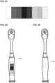
- tags can include a tag 231c having a visible pattern thereon for recognition by an imaging-based sensing subsystem ( FIGS. 2C and 2D ) or a tag 231d disposed on or in a tool and having an RFID-readable (or other wirelessly-readable) code encoded therein ( FIG. 2E ).
- Combination tags including both visible and RFID-readable codes may also be used.
- One or more of the inventory control database 180, calibration database 170, and object database store each tag's unique identifier in association with information on the associated object/tool, such that information on each object/tool can be retrieved from the database(s) based of the tool tag's identifier.
- the tags may be formed of a polycarbonate, polyester, or other suitable material, and may have an adhesive backing so as to adhere to the tools they are mounted on.
- the information encoded in the tags is encoded using differently colored bands or stripes such as those shown in the illustrative example of FIG. 2C (in which white, purple, red, black, dark blue, light blue, green, and yellow stripes are shown). Both primary colors and/or blended colors may be used.
- Each color stripe on the tag equates to a number (or alphanumeric character) and the combination of colors creates a code.
- all stripes have a same length and width; in other embodiments, adjacent stripes may have different lengths and/or widths.
- the RF sensing subsystem may be configured to sense RFID tags of tools located in all storage locations 130 and storage drawers 230 of system 100/200, or configured to sense RFID tags of tools located in a particular subset of the storage locations 130 or drawers c30 of system 100/200.
- the RF sensing subsystem is configured to sense RFID tags of tools located only in the top-most and bottom-most drawers 230 of system 200, and the RF sensing subsystem includes RFID antennas disposed directly above the top-most and bottom-most drawers 230 within system 200 to sense RFID tags of tools located in those drawers. Other configurations of RFID antennas can also be used.
- the automated calibration monitoring device 100 is configured to monitor calibration statuses of storage objects such as tools. Operation of the automated calibration monitoring device 100 will now be described in relation to FIGS. 3A-3E which show simplified flow diagrams outlining operations involved in automatically monitoring the calibration status of inventory objects such as tools.
- FIG. 3A shows a simplified flow diagram of a method 300 for automatically monitoring the calibration status of objects/tools.
- the method includes detecting a change in inventory condition of at least one object/tool in step 301.
- the automated calibration monitoring device 100 detects using its sensing subsystem 150 that the inventory status of one or more objects/tools has changed.
- the automated calibration monitoring device 100 may detect that an object/tool that was previously stored in a storage location 130 of the device 100 has been removed from or issued from the storage location.
- the automated calibration monitoring device 100 may detect that an object/tool that was previously not stored in the device 100 has been placed in or returned to a storage location 130 of the device 100.
- the automated calibration monitoring device 100 may detect that an object/tool has entered a sensing and detection range of the sensing subsystem 150, for instance as a result of the object/tool having been placed within an RF reading range of RF sensors of the sensing subsystem 150.
- an RFID sensor located adjacent to the calibration device 160 may detect an object/tool's RFID tag within its sensing range and thereby satisfy step 301.
- the automated calibration monitoring device 100 proceeds to verify the object calibration status of the object/tool in step 305.
- the verifying of the calibration status will be described in more detail in relation to FIGS. 3C-3E , below.
- the verification may involve performing a measurement of the calibration of the object/tool using the calibration device 160 and determining whether the measurement is within a calibration range for the object/tool.
- the verification may involve performing a torque calibration measurement on a tool such as a calibrated torque wrench using an electronic torque tester, and determining whether the resulting torque measurement is within an acceptable range for the wrench.
- FIG. 3B shows a simplified flow diagram of the method 301 for detecting the change in the inventory condition.
- the method 301 may be initiated as a result of detecting a change in the inventory condition of a tool/object by the sensing subsystem 150 of the automated calibration monitoring device 100.
- the change may be detected as part of performing a scan for objects/tools in the automated calibration monitoring device 100 using the sensing subsystem 150 so as to identify objects/tools that may have been issued from or returned to the device 100.
- the scan may be triggered automatically by the device, for example on a periodic basis.
- the scan may be triggered by a user, for example in response to the user selecting a calibration option on the user interface 105 of the device 100.
- the scan may also be triggered in response to detecting that a user has logged into the device 100 (e.g., using the access control device 106), that a drawer 230, door, or lock of the device 100 has been opened or closed (or is being opened or closed), that a scan request has been received via the network interface 108 (e.g., from a central calibration monitoring server), or the like.
- the method 301 includes the performing of a scan of the inventory condition of the automated calibration monitoring device 100 using the sensing subsystem 150 in step 302, and processing the sensing signals from the sensing subsystem 150.
- a scan of the inventory condition of the automated calibration monitoring device 100 using the sensing subsystem 150 in step 302, and processing the sensing signals from the sensing subsystem 150.
- one or more images of the storage locations 130 may be captured and processed by the data processing system 140 to identify objects/tools currently located in the storage locations.
- one or more RF scans of the device 100 may be performed and processed by the data processing system 140 to identify codes of RFID tags currently located within the RF range of the RF sensing antennas.
- the automated calibration monitoring device 100 proceeds in step 304 to identify objects/tools that are subject to a change in inventory condition based on the result of the scan (of step 302) and a previous record of inventory conditions for the device 100.
- the data processing system 140 may compare a list of objects/tools identified as being present in the device 100 as a result of the scan to a list of objects/tools previously recorded as being present in the device 100 to identify any objects/tools subject to a change in inventory status.
- Step 304 may result in the device 100 identifying one or more objects that are subject to a change in inventory condition, such as one or more objects that are determined to have been returned to the device 100, issued from the device 100.
- the automated calibration monitoring device 100 proceeds to verify the object calibration status of the object/tool in step 305 as described in more detail below in relation to FIGS. 3C-3E .
- FIG. 3C shows a simplified flow diagram of the method 305 for verifying the calibration status of the identified object.
- the method can include the automated calibration monitoring device 100 triggering in step 306 the taking of a calibration measurement of the object(s) identified in step 304 and, based on the result of the calibration measurement, determining an up-to-date calibration status of each object in step 314.
- Steps 306 and 314 are described in further detail in relation to FIGS. 3D and 3E , below. Note that in cases in which multiple objects/tools are identified in step 304, step 305 may be repeated for each identified object/tool.
- FIG. 3D shows a simplified flow diagram of the method 306 for triggering the taking of a calibration measurement.
- the automated calibration monitoring device 100 determines in step 307 whether the object identified in step 304 is a calibrated object that is subject to calibration. To make the determination, the automated calibration monitoring device 100 may consult the database of object information stored in memory 144 and determine whether the object is identified as a calibrated object therein. Additionally or alternatively, the automated calibration monitoring device 100 may consult the calibration database 170 or the inventory control database 180 to determine whether the object is identified therein as a calibrated object. If the object is not subject to calibration, then control is returned to step 301. Alternatively, in cases in which multiple objects are identified in step 304, control is returned to step 305 to trigger calibration measurement of a next identified object.
- the automated calibration monitoring device 100 proceeds to step 309 in which at least one calibration parameter value(s) for the identified object is retrieved from the calibration database 170.
- the calibration parameter value(s) for the identified object typically includes a calibration target value and a calibration range of acceptable calibration values.
- the calibration parameter value(s) can additionally include information on the last calibration performed on the object, such as a time of the last calibration, an elapsed time since the last calibration, a number of issuances and/or returns since the last calibration, a number of operations since the last calibration, or the like.
- step 311 the automated calibration monitoring device 100 optionally determines whether a calibration measurement of the object is needed and, in cases in which calibration is determined not to be needed, control is returned to step 301, or to step 305 in cases in which multiple objects are identified in step 304.
- the automated calibration monitoring device 100 will by default determine that a calibration measurement is needed in step 311 such that control will proceed to step 313.
- the automated calibration monitoring device 100 may determine that a calibration measurement is not needed in cases in which a calibration measurement was recently performed on the object and/or in cases in which the object was identified as being out of calibration based on a previous measurement.
- the device 100 determines that a calibration was recently performed based on the time of the last calibration (e.g., if the last calibration measurement was performed less than a predetermined threshold time t prior to the current time, such as less than 1 hour, 1 day, or 1 week prior to the current time), an elapsed time since the last calibration (e.g., if the elapsed time is less than the predetermined threshold time), a number of issuances and/or returns since the last calibration (e.g., if the number of issuances since the last calibration is less than a predetermined threshold number, such as less than 2 issuances), a number of operations since the last calibration (e.g., if the number of operations involving the object since the last calibration is less than a predetermined threshold number, such as less than 10 fastening operations), or the like.
- a predetermined threshold time t prior to the current time such as less than 1 hour, 1 day, or 1 week prior to the current time
- an elapsed time since the last calibration
- the calibration measurement of the object is performed.
- the measurement of calibration can include the automated calibration monitoring device 100 providing instructions to a user via the user interface 105 to perform the calibration measurement.
- the measurement can further include the device 100 providing the calibration device 160 with the calibration target value for the object in order to enable the calibration device 160 to perform the measurement on the basis of the target value.
- the calibration device 160 returns to the device 100 a calibration measurement value corresponding to the measured calibration of the object.
- FIG. 3E shows a simplified flow diagram of the method 314 for determining the calibration status of the object.
- the automated calibration monitoring device 100 receives the calibration measurement value for the object as obtained in step 313 from the calibration device 160.
- the device 100 proceeds in step 315 to compare the calibration measurement value to the calibration range of acceptable values to determine whether the measurement value falls within the range of acceptable values for the object. If the calibration measurement value falls within the calibration range of acceptable values, the device 100 determines that the object is in calibration; alternatively, if the calibration measurement value falls outside of the calibration range of acceptable values, the device 100 determines that the object is out of calibration.
- the device proceeds in step 317 to update the calibration status (in calibration, or out of calibration) for the object in the calibration database 170 and/or the inventory control database (e.g., 180, or stored in memory 144).
- the calibration database 170 may additionally be updated to store the calibration measurement value and other data relating to the calibration measurement of step 313 (e.g., date/time of calibration measurement, calibration target value used, identity of the calibration device 160 used for measurement, etc.).
- the automated calibration monitoring device 100 can enable or disable the issue and/or return of objects/tools based on the updated object calibration status in step 319. For example, upon determining that the object/tool is in calibration, the automated calibration monitoring device 100 may enable or authorize issue and/or return of the object/tool from/to the storage locations of the device 100. Alternatively, upon determining that the object/tool is out of calibration, the automated calibration monitoring device 100 may disable or block issue of the object/tool from the device 100 and may request that the object/tool be promptly returned to the device 100.
- the foregoing discussion has focused on situations in which one or more calibrated objects/tools (e.g., a torque tool such as a torque wrench) are issued.
- the system can handle situations in which a single object/tool is issued by assuming the single issued tool is the only tool available for calibration measurement and by associating all calibration measurement related data and results received from the calibration device 160 pertain to the single object/tool being issued or returned.
- An alternative provides for the system to select which object/tool is to be subject to calibration measurement and to display system-selected object/tool's data on the display screen. The user is then charged with providing the selected object/tool to the calibration device 160 for the calibration measurement. After this tool is tested, a next object/tool is selected by the system and identification for the next object/tool is displayed. The process is repeated until all objects/tools being issued and returned are subject to calibration measurement.
- a further alternative provides a sensing subsystem 150 on or adjacent to the calibration device 160 to enable the calibration device (e.g., a torque testing device) to directly sense and identify the unique identifier attached to an object/tool provided therein for calibration.
- the calibration device e.g., a torque testing device
- an RFID sensor provided adjacent to the calibration device 160 and having a short RFID reading range (e.g., up to 20 centimeters in front of the calibration device 160) may be used to automatically identify objects/tools with RFID tags that are located in close proximity to the calibration device 160.
- the calibration device 160 can then report measured calibration values together with the identity of the object/tool detected in its close proximity to the automated calibration monitoring system.
- a purpose of the systems and methods disclosed herein is to provide an efficient process for enabling the automated monitoring of tool calibration using, e.g., an automated tool control system in concert with a calibration device such as torque testing device.
- a calibration device such as torque testing device.
- a number of efficiencies and advanced functionalities are enabled through the combined use of the devices executing advanced functions enabled by software programming executed on system processors.
- the systems and method described above make use of databases storing calibration data for objects/tools.
- the calibration monitoring system 190 can include individual data stores or databases in individual calibration monitoring devices 100a-100n and/or one or more centralized master databases residing in one or more central servers.
- calibration related data for each of the calibrated objects, tools, and other inventory items are pre-stored in the calibration database 170 and/or preloaded into the memory 144 of an automated calibration monitoring device 100 for use in calibration status monitoring as described above.
- the calibration data for tools stored in the calibration database 170 includes one or more of the data entries shown in Table 1 below: Object/Tool ID Object/Tool Description Calibration Target Value Calibration Acceptable Range Last Calibration Measurement Value Last Calibration Timestamp X450-400 ATECH3F250 Torque Wrench 100 ft-lb 98-102 ft-lb 100 ft-lb 09/20/2017 12:00:00 GMT ... ... ... ... ... ... ... ... ... ... ... ... ...
- the calibration database 170 can store the following data for each calibration tool/object:
- the calibration database 170 can store additional calibration data including an object/tool calibration interval or schedule (e.g., indicating a maximum interval between calibrations of the instruction), that can include a next calibration due date (e.g., calculated based on the object calibration schedule and the date of the last calibration measurement) which may be recorded by date or by time interval (e.g., measured in minutes, hours, days, weeks, or the like), by number of uses, by number of days, or the like.
- the calibration interval or schedule when stored, may be specific to each tool/object such that a different schedule is stored for each tool; specific to a category of tool/object such that a same schedule is stored for each tool category while different schedules are stored for different tool categories; or the same for all tools/objects.
- the calibration database 170 can store further calibration data including object calibration data, including maximum and/or minimum acceptable torque level ranges at various loads, and/or maximum and/or minimum acceptable torque angular displacement ranges at various loads (e.g., in the case the tools/objects are calibrated torque wrenches).
- the calibration database 170 can store further calibration data including process data, which may include (a) calibration and test process data per ISO 6789-2:2017; (b) conformance tests to ISO 6789-1:2017; (c) uncertainty tests to ISO 6789-2:2017; (d) 20%, 60%, 100% max torque values for each tool/object; (e) number of test points required; (f) a target torque value; and/or (g) upper and lower limits.
- process data may include (a) calibration and test process data per ISO 6789-2:2017; (b) conformance tests to ISO 6789-1:2017; (c) uncertainty tests to ISO 6789-2:2017; (d) 20%, 60%, 100% max torque values for each tool/object; (e) number of test points required; (f) a target torque value; and/or (g) upper and lower limits.
- One of the calibration database 170, the inventory control database 180, and/or the memory 144 of the automated calibration monitoring device 100 may additionally store data associated with each object/tool including data identifying the object/tool (such as a part number, a description, or other a unique identifier), a storage location for the object/tool within the device 100, a manufacturer or supplier, related objects/tools/parts, or the like.
- Data associated to the specific torque device and related to calibration of the device can include calibration intervals, scheduled calibration, last calibration, optimal torque profile, torque applied and resulting angular displacement, calibrated torque values, pass/fail criteria, or the like.
- ACM automated calibration monitoring
- FIGS. 4A-4D show various system connection configurations that may be used in the automated calibration monitoring systems described above.
- a first configuration is used in which the object/tool 401 subject to calibration measurement is not configured for electronic data transfer or communication (or the object/tool's electronic data transfer or communication functionality is not used).
- the calibration device 160 can be co-located with the ACM device 100 and be communicatively connected to the ACM device for communication of calibration measurements.
- the ACM device 100 e.g., a tool control system toolbox 200
- the networked calibration and/or inventory control databases 170/180 for information exchange purposes.
- FIG. 4B shows a second configuration in which the calibrated object/tool 401 is configured for electronic data transfer and is communicatively connected to the calibration device 160 (e.g., a torque tester).
- the calibration device 160 is again communicatively connected to the ACM device 100.
- the ACM device 100 is communicatively connected to the networked calibration and/or inventory control databases 170/180 for information exchange purposes.
- FIG. 4C shows a third configuration in which the calibrated object/tool 401 is not configured for electronic data transfer (or the calibration object/tool's electronic data transfer functionality is not used).
- the calibration device 160 can be located at the ACM device 100 or remote from the ACM device 100 and is communicatively connected to the networked calibration and/or inventory control databases 170/180 for information exchange purposes.
- the ACM device 100 and the calibration device 160 are thus both independently connected to the networked calibration and/or inventory control databases 170/180 for information exchange purposes.
- FIG. 4D shows a fourth configuration in which the calibrated object/tool 401 is configured for electronic data transfer.
- the calibrated object/tool 401 and the calibration device 160 can be located at the ACM device 100 or can be remote from the ACM device 100.
- the calibrated object/tool 401, the ACM device 100, and the calibration device 160 are all communicatively connected to the networked calibration and/or inventory control databases 170/180 for information exchange purposes.
- calibrated tools including torque devices are stored in a central repository (e.g., a tool crib) in many work environments and the tools are issued from the central repository to technicians for use in disparate or remote work locations.
- a calibration device 160 can be provided within a tool crib or at the point of issue (e.g., entrance and exit) of the tool crib to enable calibration measurements to be performed at the time of entrance or exit from the tool crib.
- the calibration monitoring system automatically identifies the object/tool and retrieves calibration data associated to the object/tool. The system also provides an alert to the user that the object/tool must have its calibration measured prior to issuance.
- Calibration devices 160 such as electronic torque testers can be equipped with the capability to measure or test the calibration of tools (such as torque devices) using manually input pass/fail criteria and to display results. More advanced versions of the calibration tools can electrically transfer torque measurement data to software packages for analysis. The transfer and analysis can be done locally on the calibration device or the data can be transferred to another device (e.g., an automated calibration monitoring device) across a network. In either case, however, the calibration device did not previously have the capability to automatically identify specific objects/tools/devices and associate pass/fail criteria or test data to the system for the specific identified object/tool/device. For example, previously, the identity of the object/tool/device to be tested had to be manually input into the calibration device by a user.
- the calibration device 160 (e.g., torque tester) is configured with data processing and data storage capabilities, computing software, wired and/or wireless network communications capabilities, a user interface, and the means for automatically inputting data.
- the calibration device 160 may be powered by an AC power supply, by batteries, or by a combination of both batteries and/or AC power.
- the user interface may be an LED display, an LCD display or monitor, or other currently utilized technologies for displaying information.
- the data input interface for the calibration device 160 can include wired or wireless communications capabilities, keyboards, keypads, mice, RFID, optical (barcode) scanners, cameras, or the like.
- the automated calibration monitoring device can be used for auditing purposes.
- an object/tool e.g., a torque device
- the system may retrieve from memory data indicating the work location and/or the work order that the object/tool was issued under.
- the system can produce a report indicating that the object/tool failed the calibration measurement test and identifying the work location and/or the work order under which the object/tool was last issued.
- the report can be automatically distributed by email or text message to appropriate individuals as identified by the system administrator.
- the report can also indicate all work locations and/or work orders that the object/tool was issued to since the tool's last in-calibration measurement.
- the system can also list in the report each of the products (e.g., individual fasteners) that may have been improperly worked on since the object/tool was last issued and passed a calibration measurement test.
- the system can also create a validation report showing all calibrated objects/tools issued against a work location or work order and their recorded calibration measurement test values and other pertinent data.
- the automated calibration monitoring device 100 is operative to request calibration measurements (e.g., torque measurements) from a calibration device 160 and validate the calibrations status of tools or other inventory objects stored in the automated calibration monitoring device 100.
- the tools/objects generally have unique identifiers associated therewith and associated with tags provided on the tools/objects, and the identifiers and associated tools/objects devices are identified in inventory control and/or calibration database(s) as being tools/objects for which calibration is to be monitored.
- the automated calibration monitoring device 100 can thus recognize calibrated tools/objects through recognition of the unique identifiers attached to the tools/objects when the tools/objects are issued from or returned to the system.
- the tools/objects further have calibration data, including target calibration values, stored and associated therewith in the database(s).
- the automated calibration monitoring system can thus require that a calibration measurement or test be performed on a tool/object to confirm whether the calibrated tool/object is accurately in calibration prior to and/or after each use of the object.
- the parameters of the calibration monitoring (used to determine whether the tool is in calibration or out of calibration) can be determined by a user but are generally retrieved from the calibration database as calibration target values associated in the database with the unique identifier of the tools/objects.
- the automated calibration monitoring device 100 and tool control system 200 are thus programmed to compare calibration data such as torque data for a tool as obtained from the calibration measurement device (e.g., torque tester) with one or more calibration target values for the tool, such as calibration values which are associated with a unique identifier of the tool and which are stored in one or more of the inventory control and calibration database(s). Based on the comparison, the automated calibration monitoring device 100 can determine whether the tool satisfies calibration requirements set by the calibration values. If the calibration requirements are not satisfied, the automated calibration monitoring device 100 may identify the tool as being out of calibration and may issue an alert to any user seeking to issue or check-out the tool from the system 100. The automated calibration monitoring system 100 can thus allow issue and return of the calibrated tool/object if the results of the calibration measurement fall within an acceptable calibration range stored for each tool/object in the calibration database.
- calibration data such as torque data for a tool as obtained from the calibration measurement device (e.g., torque tester)
- calibration target values for the tool such as calibration values which are associated with a unique
- the automated calibration monitoring system can bar issue of the calibrated object/tool if the calibration measurement value does not meet or fall within the acceptable range of calibration values for the tool/object.
- the system can issue audible and visual instructions to return the tool/object which failed to meet the calibration test criteria to an appropriate storage location in the device.
- the system can alternatively or additionally issue audible and visual instructions to transfer the tool/object which failed to meet the calibration test criteria to an appropriate location where the repair and re-calibration processes occur.
- the automated calibration monitoring system can issue status alerts to users, system administrators, calibration lab personnel, or the like when the tested tool/object fails to meet the calibration criteria pre-stored in the calibration database in order to enable the alerted parties to appropriately respond to the situation (e.g., by recalibrating the object, by flagging work orders associated with the improper calibration, or the like).
- the system can require the object/tool be returned to its appropriate storage location within the storage device if the calibration measurement results do not meet the acceptable calibration requirements when the object/tool is being returned to the storage device after use.
- the system can require that the object/tool be transferred to an appropriate calibration lab if the calibration measurement results do not meet the calibration requirement.
- the automated calibration monitoring system can issue status alerts to users, system administrators, calibration lab personnel, or the like when the tested object/tool fails to meet the calibration measurement criteria pre-stored in the calibration database in order to enable the alerted parties to appropriately respond to the situation (e.g., by recalibrating the object, by flagging work orders associated with the improper calibration, or the like).
- the calibration monitoring device 100 utilizes one or more of various sensing technologies to determine issue/return or presence/absence of objects from its storage.
- the issue/return or presence/absence of objects can be sensed using one or more of imaging-based sensing technology (e.g., using cameras), RFID-based sensing technology, individual switches or sensors (e.g., contact, capacitive, inductive, weight, or other sensors), such as sensing technologies used in automated tool control (ATC) imaging toolboxes, ATC RFID lockers, and/or ATC tool crib management systems.
- ATC automated tool control
- Unique identifiers such as color coded tags, RFID tags, bar codes, etc.
- FIG. 5 provides a functional block diagram illustrations of a general purpose computer hardware platform that may be used as a network or host computer platform to implement a server
- the computer platform of FIG. 5 may be used to implement a server supporting the calibration database 170 and/or the automated inventory control database 180 and the associated functionalities as described herein, and may be used to implement an inventory control server or calibration monitoring server performing one or more of the functionalities described in FIGS. 3A-3E .
- the computer platform of FIG 5 may also be combined with user interface elements to implement a personal computer or other type of work station or terminal device, such as to implement computing functionalities within a calibration device 160 or object/tool 401. It is believed that those skilled in the art are familiar with the structure, programming and general operation of such computer equipment and as a result the drawings should be self-explanatory.
- a server for example that shown in FIG. 5 , includes a data communication interface for packet data communication.
- the server also includes a central processing unit (CPU), in the form of one or more processors, for executing program instructions.
- the server platform typically includes an internal communication bus, program storage and data storage for various data files to be processed and/or communicated by the server, although the server often receives programming and data via network communications.
- the hardware elements, operating systems and programming languages of such servers are conventional in nature, and it is presumed that those skilled in the art are adequately familiar therewith.
- the server functions may be implemented in a distributed fashion on a number of similar platforms, to distribute the processing load.
Landscapes
- Engineering & Computer Science (AREA)
- Business, Economics & Management (AREA)
- Mechanical Engineering (AREA)
- Physics & Mathematics (AREA)
- General Physics & Mathematics (AREA)
- Economics (AREA)
- Theoretical Computer Science (AREA)
- General Business, Economics & Management (AREA)
- Marketing (AREA)
- Strategic Management (AREA)
- Tourism & Hospitality (AREA)
- Human Resources & Organizations (AREA)
- Finance (AREA)
- Entrepreneurship & Innovation (AREA)
- Health & Medical Sciences (AREA)
- Manufacturing & Machinery (AREA)
- Accounting & Taxation (AREA)
- Primary Health Care (AREA)
- Development Economics (AREA)
- General Health & Medical Sciences (AREA)
- Operations Research (AREA)
- Quality & Reliability (AREA)
- Chemical & Material Sciences (AREA)
- Analytical Chemistry (AREA)
- General Factory Administration (AREA)
- Details Of Spanners, Wrenches, And Screw Drivers And Accessories (AREA)
- Warehouses Or Storage Devices (AREA)
- Automatic Tape Cassette Changers (AREA)
Applications Claiming Priority (3)
| Application Number | Priority Date | Filing Date | Title |
|---|---|---|---|
| US201762567510P | 2017-10-03 | 2017-10-03 | |
| EP18786615.7A EP3691833B1 (de) | 2017-10-03 | 2018-09-27 | Überwachung eines werkzeugkalibrierungsstatus in automatisierten werkzeugsteuerungssystemen |
| PCT/US2018/053105 WO2019070501A1 (en) | 2017-10-03 | 2018-09-27 | MONITORING TOOL CALIBRATION STATUS IN AUTOMATED TOOL CONTROL SYSTEMS |
Related Parent Applications (1)
| Application Number | Title | Priority Date | Filing Date |
|---|---|---|---|
| EP18786615.7A Division EP3691833B1 (de) | 2017-10-03 | 2018-09-27 | Überwachung eines werkzeugkalibrierungsstatus in automatisierten werkzeugsteuerungssystemen |
Publications (2)
| Publication Number | Publication Date |
|---|---|
| EP4546246A2 true EP4546246A2 (de) | 2025-04-30 |
| EP4546246A3 EP4546246A3 (de) | 2025-07-16 |
Family
ID=63858191
Family Applications (2)
| Application Number | Title | Priority Date | Filing Date |
|---|---|---|---|
| EP25151736.3A Pending EP4546246A3 (de) | 2017-10-03 | 2018-09-27 | Überwachung des werkzeugkalibrierungsstatus in automatisierten werkzeugsteuerungssystemen |
| EP18786615.7A Active EP3691833B1 (de) | 2017-10-03 | 2018-09-27 | Überwachung eines werkzeugkalibrierungsstatus in automatisierten werkzeugsteuerungssystemen |
Family Applications After (1)
| Application Number | Title | Priority Date | Filing Date |
|---|---|---|---|
| EP18786615.7A Active EP3691833B1 (de) | 2017-10-03 | 2018-09-27 | Überwachung eines werkzeugkalibrierungsstatus in automatisierten werkzeugsteuerungssystemen |
Country Status (8)
| Country | Link |
|---|---|
| US (4) | US11085841B2 (de) |
| EP (2) | EP4546246A3 (de) |
| JP (3) | JP7274467B2 (de) |
| CN (2) | CN111246973B (de) |
| AU (1) | AU2018345532B2 (de) |
| ES (1) | ES3008484T3 (de) |
| TW (4) | TW202505438A (de) |
| WO (1) | WO2019070501A1 (de) |
Families Citing this family (22)
| Publication number | Priority date | Publication date | Assignee | Title |
|---|---|---|---|---|
| US10987785B2 (en) * | 2016-08-15 | 2021-04-27 | Gauthier Biomedical, Inc. | Electronic torque wrench with transducer check function |
| ES3008484T3 (en) | 2017-10-03 | 2025-03-24 | Snap On Incorporated | Monitoring of tool calibration status in automated tool control systems |
| CN111868718A (zh) * | 2018-04-30 | 2020-10-30 | 惠普发展公司,有限责任合伙企业 | 服务终端机访问 |
| US11861446B2 (en) * | 2018-07-24 | 2024-01-02 | Illinois Tool Works Inc. | Method and apparatus for using encoded information for material preparation and analysis equipment |
| US10762411B1 (en) * | 2019-03-01 | 2020-09-01 | Amazon Technologies, Inc. | Smart shelf with self calibration |
| CN110076739B (zh) * | 2019-04-24 | 2024-05-21 | 广州新科宇航科技有限公司 | 一种用于飞机维修的rfid工具车 |
| IL266295B2 (en) | 2019-04-28 | 2024-02-01 | Ham Let Israel Canada Ltd | key |
| US11573553B2 (en) * | 2019-09-30 | 2023-02-07 | Ingersoll-Rand Industrial U.S., Inc. | Portable calibration system |
| AU2020372313A1 (en) * | 2019-10-23 | 2022-04-14 | Snap-On Incorporated | Data acquisition using machine-readable optical symbols |
| US12086758B2 (en) * | 2019-11-01 | 2024-09-10 | Tvrdy 8, Llc | Horizontal tool staging system and tool staging accessories with secure enclosure and tool locating capabilities |
| EP4100209A4 (de) * | 2020-02-17 | 2024-03-06 | Apex Brands, Inc. | Automatische drehmomentkalibrierung |
| AT523168B1 (de) * | 2020-03-18 | 2021-06-15 | Avl List Gmbh | Verfahren zum Justieren eines piezoelektrischen Drehmomentsensors |
| WO2022020787A1 (en) * | 2020-07-24 | 2022-01-27 | Schneider Electric USA, Inc. | Electrical equipment management |
| CA3197899A1 (en) * | 2020-08-31 | 2022-02-28 | Snap-On Incorporated | Wireless torque wrench with torque specifications |
| US12215729B2 (en) | 2021-12-08 | 2025-02-04 | Mueller International, Llc | Smart operating nut |
| CN114530016B (zh) * | 2022-01-04 | 2023-02-14 | 成都美透科技有限公司 | 基于区块链的美容仪租赁方法及装置、系统、存储介质 |
| TWI833253B (zh) * | 2022-06-21 | 2024-02-21 | 奇景光電股份有限公司 | 觸控面板自動檢測機台 |
| WO2024045121A1 (en) * | 2022-09-01 | 2024-03-07 | Apex Brands, Inc. | A torque tester for verifying multiple electronic torque wrenches |
| CN115674125B (zh) * | 2022-09-30 | 2024-11-12 | 贵州电网有限责任公司 | 一种基于rfid的检修工具箱 |
| CN115625679B (zh) * | 2022-10-25 | 2025-04-29 | 北京云算智通科技有限公司 | 一种轨道车辆数值化检修工具车 |
| TWI842451B (zh) * | 2023-03-23 | 2024-05-11 | 瞬豐實業股份有限公司 | 手工具操作管理裝置 |
| CN116869216B (zh) * | 2023-06-28 | 2025-11-25 | 张家口卷烟厂有限责任公司 | 一种不同规格卷烟的喇叭嘴支座校准工装及其使用方法 |
Citations (1)
| Publication number | Priority date | Publication date | Assignee | Title |
|---|---|---|---|---|
| US9741014B2 (en) | 2015-04-15 | 2017-08-22 | Snap-On Incorporated | Automated asset management system with multiple sensing technologies |
Family Cites Families (21)
| Publication number | Priority date | Publication date | Assignee | Title |
|---|---|---|---|---|
| JP2006098074A (ja) * | 2004-09-28 | 2006-04-13 | Fujitsu Support & Service Kk | 測定履歴記録型測定器 |
| JP4953656B2 (ja) * | 2006-02-23 | 2012-06-13 | 中国電力株式会社 | 器具管理システム及び器具管理方法 |
| US7932824B2 (en) * | 2006-10-13 | 2011-04-26 | RFID Mexico, S.A. DE C.V. | Item tracking system |
| US7557709B2 (en) * | 2006-10-13 | 2009-07-07 | RFID Mexico, S.A. DE C.V. | Item tracking system |
| JP2008307671A (ja) * | 2007-06-18 | 2008-12-25 | Tohnichi Mfg Co Ltd | トレーサビリティの取れる無線式トルク工具装置 |
| EP2159006A4 (de) * | 2007-06-18 | 2012-05-23 | Tohnichi Mfg Co Ltd | Drehmomentschrauber |
| US8630819B2 (en) * | 2008-02-18 | 2014-01-14 | The Boeing Company | System and method for electronic inspection and record creation of assembly, repair and maintenance operations |
| DE202008002913U1 (de) * | 2008-02-29 | 2008-05-08 | Eduard Wille Gmbh & Co. Kg | Betätigungsvorrichtung zum Kalibrieren von Drehmomentschlüsseln |
| JP5568374B2 (ja) * | 2010-05-18 | 2014-08-06 | 株式会社東日製作所 | 測定対象指示装置及び測定対象指示システム |
| TWI429890B (zh) * | 2010-12-01 | 2014-03-11 | Ind Tech Res Inst | 數位扭力工具校正方法、驗證方法及校正系統 |
| DE102011001073B4 (de) * | 2011-03-03 | 2013-10-17 | Eduard Wille Gmbh & Co. Kg | Verfahren zum Kalibrieren von Werkzeugen |
| DE102011001076B4 (de) * | 2011-03-03 | 2014-11-06 | Eduard Wille Gmbh & Co. Kg | Verfahren zur Verwaltung von Werkzeugen |
| US9898698B2 (en) * | 2011-07-01 | 2018-02-20 | The Boeing Company | Production tool having RFID device mounted within a dielectric inclusion |
| TWI441708B (zh) * | 2011-10-24 | 2014-06-21 | Quaser Machine Tools Inc | 工具機自動尋邊補正系統 |
| CN104486975B (zh) * | 2012-06-12 | 2018-05-08 | 实耐宝公司 | 库存控制系统 |
| CA2815864C (en) * | 2012-06-30 | 2018-04-17 | The Boeing Company | Production tool having rfid device mounted within a dielectric inclusion |
| CN104517170A (zh) * | 2013-09-30 | 2015-04-15 | 北大方正集团有限公司 | 物品监控设备和物品监控方法 |
| DE102014110192A1 (de) | 2014-07-21 | 2016-01-21 | Fischerwerke Gmbh & Co. Kg | Befestiger für eine Montageschiene |
| WO2016023081A1 (en) * | 2014-08-12 | 2016-02-18 | Chambers Alisdair | Storage device and item management system |
| CN104345721B (zh) * | 2014-11-13 | 2018-04-10 | 黄河科技学院 | 一种基于rfid技术的物资状态监控系统与方法 |
| ES3008484T3 (en) | 2017-10-03 | 2025-03-24 | Snap On Incorporated | Monitoring of tool calibration status in automated tool control systems |
-
2018
- 2018-09-27 ES ES18786615T patent/ES3008484T3/es active Active
- 2018-09-27 WO PCT/US2018/053105 patent/WO2019070501A1/en not_active Ceased
- 2018-09-27 EP EP25151736.3A patent/EP4546246A3/de active Pending
- 2018-09-27 EP EP18786615.7A patent/EP3691833B1/de active Active
- 2018-09-27 CN CN201880064833.0A patent/CN111246973B/zh active Active
- 2018-09-27 CN CN202210271924.XA patent/CN114571398B/zh active Active
- 2018-09-27 AU AU2018345532A patent/AU2018345532B2/en active Active
- 2018-09-27 JP JP2020519032A patent/JP7274467B2/ja active Active
- 2018-10-02 TW TW113138516A patent/TW202505438A/zh unknown
- 2018-10-02 TW TW107134767A patent/TWI749263B/zh active
- 2018-10-02 TW TW110142174A patent/TWI786942B/zh active
- 2018-10-02 TW TW111144562A patent/TWI859634B/zh active
- 2018-10-03 US US16/150,737 patent/US11085841B2/en active Active
-
2021
- 2021-06-30 US US17/364,607 patent/US11686635B2/en active Active
-
2023
- 2023-05-01 JP JP2023075571A patent/JP7544904B2/ja active Active
- 2023-05-10 US US18/315,420 patent/US12222256B2/en active Active
-
2024
- 2024-08-21 JP JP2024139718A patent/JP2024164129A/ja active Pending
-
2025
- 2025-01-23 US US19/035,675 patent/US20250258050A1/en active Pending
Patent Citations (1)
| Publication number | Priority date | Publication date | Assignee | Title |
|---|---|---|---|---|
| US9741014B2 (en) | 2015-04-15 | 2017-08-22 | Snap-On Incorporated | Automated asset management system with multiple sensing technologies |
Also Published As
| Publication number | Publication date |
|---|---|
| TWI786942B (zh) | 2022-12-11 |
| TW202209204A (zh) | 2022-03-01 |
| TWI749263B (zh) | 2021-12-11 |
| JP7544904B2 (ja) | 2024-09-03 |
| US20210396613A1 (en) | 2021-12-23 |
| CN111246973B (zh) | 2022-04-05 |
| US11686635B2 (en) | 2023-06-27 |
| TWI859634B (zh) | 2024-10-21 |
| CN114571398A (zh) | 2022-06-03 |
| TW202505438A (zh) | 2025-02-01 |
| US20250258050A1 (en) | 2025-08-14 |
| TW201923670A (zh) | 2019-06-16 |
| AU2018345532A1 (en) | 2020-04-16 |
| US20230280224A1 (en) | 2023-09-07 |
| US20190101463A1 (en) | 2019-04-04 |
| AU2018345532B2 (en) | 2022-09-29 |
| JP7274467B2 (ja) | 2023-05-16 |
| US11085841B2 (en) | 2021-08-10 |
| JP2024164129A (ja) | 2024-11-26 |
| TW202314611A (zh) | 2023-04-01 |
| CN114571398B (zh) | 2024-08-16 |
| EP4546246A3 (de) | 2025-07-16 |
| JP2020536820A (ja) | 2020-12-17 |
| WO2019070501A1 (en) | 2019-04-11 |
| ES3008484T3 (en) | 2025-03-24 |
| CN111246973A (zh) | 2020-06-05 |
| JP2023120181A (ja) | 2023-08-29 |
| US12222256B2 (en) | 2025-02-11 |
| EP3691833A1 (de) | 2020-08-12 |
| EP3691833B1 (de) | 2025-01-15 |
Similar Documents
| Publication | Publication Date | Title |
|---|---|---|
| US12222256B2 (en) | Monitoring of tool calibration status in automated tool control systems | |
| US10943112B2 (en) | Automated tool data generation in automated asset management systems | |
| EP2416298A2 (de) | Bestandskontrollsystem für tragbare behälter | |
| CN114341904A (zh) | 在自动化工具控制系统中管理具有分配状态的对象 | |
| WO2016023081A1 (en) | Storage device and item management system | |
| US20230249913A1 (en) | Automated tool control device managed in a tool crib management system | |
| HK40026073A (en) | Monitoring of tool calibration status in automated tool control systems | |
| HK40026073B (en) | Monitoring of tool calibration status in automated tool control systems |
Legal Events
| Date | Code | Title | Description |
|---|---|---|---|
| PUAI | Public reference made under article 153(3) epc to a published international application that has entered the european phase |
Free format text: ORIGINAL CODE: 0009012 |
|
| STAA | Information on the status of an ep patent application or granted ep patent |
Free format text: STATUS: REQUEST FOR EXAMINATION WAS MADE |
|
| 17P | Request for examination filed |
Effective date: 20250213 |
|
| AC | Divisional application: reference to earlier application |
Ref document number: 3691833 Country of ref document: EP Kind code of ref document: P |
|
| AK | Designated contracting states |
Kind code of ref document: A2 Designated state(s): AL AT BE BG CH CY CZ DE DK EE ES FI FR GB GR HR HU IE IS IT LI LT LU LV MC MK MT NL NO PL PT RO RS SE SI SK SM TR |
|
| REG | Reference to a national code |
Ref country code: DE Ref legal event code: R079 Free format text: PREVIOUS MAIN CLASS: G06Q0050040000 Ipc: B25B0023000000 |
|
| PUAL | Search report despatched |
Free format text: ORIGINAL CODE: 0009013 |
|
| AK | Designated contracting states |
Kind code of ref document: A3 Designated state(s): AL AT BE BG CH CY CZ DE DK EE ES FI FR GB GR HR HU IE IS IT LI LT LU LV MC MK MT NL NO PL PT RO RS SE SI SK SM TR |
|
| RIC1 | Information provided on ipc code assigned before grant |
Ipc: B25B 23/00 20060101AFI20250611BHEP Ipc: B25B 23/14 20060101ALI20250611BHEP Ipc: B25H 3/00 20060101ALI20250611BHEP Ipc: G01L 25/00 20060101ALI20250611BHEP Ipc: B25H 3/02 20060101ALI20250611BHEP Ipc: G06Q 10/087 20230101ALI20250611BHEP Ipc: G06Q 50/04 20120101ALI20250611BHEP |
|
| STAA | Information on the status of an ep patent application or granted ep patent |
Free format text: STATUS: EXAMINATION IS IN PROGRESS |