EP4545802A1 - Hydraulische antriebsvorrichtung - Google Patents
Hydraulische antriebsvorrichtung Download PDFInfo
- Publication number
- EP4545802A1 EP4545802A1 EP23826869.2A EP23826869A EP4545802A1 EP 4545802 A1 EP4545802 A1 EP 4545802A1 EP 23826869 A EP23826869 A EP 23826869A EP 4545802 A1 EP4545802 A1 EP 4545802A1
- Authority
- EP
- European Patent Office
- Prior art keywords
- valve
- regeneration
- end port
- hydraulic pump
- pump motor
- Prior art date
- Legal status (The legal status is an assumption and is not a legal conclusion. Google has not performed a legal analysis and makes no representation as to the accuracy of the status listed.)
- Pending
Links
Images

Classifications
-
- F—MECHANICAL ENGINEERING; LIGHTING; HEATING; WEAPONS; BLASTING
- F15—FLUID-PRESSURE ACTUATORS; HYDRAULICS OR PNEUMATICS IN GENERAL
- F15B—SYSTEMS ACTING BY MEANS OF FLUIDS IN GENERAL; FLUID-PRESSURE ACTUATORS, e.g. SERVOMOTORS; DETAILS OF FLUID-PRESSURE SYSTEMS, NOT OTHERWISE PROVIDED FOR
- F15B11/00—Servomotor systems without provision for follow-up action ; Circuits therefor
- F15B11/02—Systems essentially incorporating special features for controlling the speed or the actuating force of an output member
- F15B11/024—Systems essentially incorporating special features for controlling the speed or the actuating force of an output member by means of differential connection of the servomotor lines, e.g. regenerative circuits
-
- E—FIXED CONSTRUCTIONS
- E02—HYDRAULIC ENGINEERING; FOUNDATIONS; SOIL SHIFTING
- E02F—DREDGING; SOIL-SHIFTING
- E02F9/00—Component parts of dredgers or soil-shifting machines, not restricted to one of the kinds covered by groups E02F3/00 - E02F7/00
- E02F9/20—Drives; Control devices
- E02F9/22—Hydraulic or pneumatic drives
- E02F9/2217—Hydraulic or pneumatic drives with energy recovery arrangements, e.g. using accumulators, flywheels
-
- E—FIXED CONSTRUCTIONS
- E02—HYDRAULIC ENGINEERING; FOUNDATIONS; SOIL SHIFTING
- E02F—DREDGING; SOIL-SHIFTING
- E02F9/00—Component parts of dredgers or soil-shifting machines, not restricted to one of the kinds covered by groups E02F3/00 - E02F7/00
- E02F9/24—Safety devices, e.g. for preventing overload
-
- F—MECHANICAL ENGINEERING; LIGHTING; HEATING; WEAPONS; BLASTING
- F15—FLUID-PRESSURE ACTUATORS; HYDRAULICS OR PNEUMATICS IN GENERAL
- F15B—SYSTEMS ACTING BY MEANS OF FLUIDS IN GENERAL; FLUID-PRESSURE ACTUATORS, e.g. SERVOMOTORS; DETAILS OF FLUID-PRESSURE SYSTEMS, NOT OTHERWISE PROVIDED FOR
- F15B11/00—Servomotor systems without provision for follow-up action ; Circuits therefor
- F15B11/02—Systems essentially incorporating special features for controlling the speed or the actuating force of an output member
- F15B11/04—Systems essentially incorporating special features for controlling the speed or the actuating force of an output member for controlling the speed
- F15B11/042—Systems essentially incorporating special features for controlling the speed or the actuating force of an output member for controlling the speed by means in the feed line
- F15B11/0423—Systems essentially incorporating special features for controlling the speed or the actuating force of an output member for controlling the speed by means in the feed line by controlling pump output or bypass, other than to maintain constant speed
-
- F—MECHANICAL ENGINEERING; LIGHTING; HEATING; WEAPONS; BLASTING
- F15—FLUID-PRESSURE ACTUATORS; HYDRAULICS OR PNEUMATICS IN GENERAL
- F15B—SYSTEMS ACTING BY MEANS OF FLUIDS IN GENERAL; FLUID-PRESSURE ACTUATORS, e.g. SERVOMOTORS; DETAILS OF FLUID-PRESSURE SYSTEMS, NOT OTHERWISE PROVIDED FOR
- F15B21/00—Common features of fluid actuator systems; Fluid-pressure actuator systems or details thereof, not covered by any other group of this subclass
- F15B21/08—Servomotor systems incorporating electrically operated control means
- F15B21/087—Control strategy, e.g. with block diagram
-
- F—MECHANICAL ENGINEERING; LIGHTING; HEATING; WEAPONS; BLASTING
- F15—FLUID-PRESSURE ACTUATORS; HYDRAULICS OR PNEUMATICS IN GENERAL
- F15B—SYSTEMS ACTING BY MEANS OF FLUIDS IN GENERAL; FLUID-PRESSURE ACTUATORS, e.g. SERVOMOTORS; DETAILS OF FLUID-PRESSURE SYSTEMS, NOT OTHERWISE PROVIDED FOR
- F15B21/00—Common features of fluid actuator systems; Fluid-pressure actuator systems or details thereof, not covered by any other group of this subclass
- F15B21/14—Energy-recuperation means
-
- F—MECHANICAL ENGINEERING; LIGHTING; HEATING; WEAPONS; BLASTING
- F15—FLUID-PRESSURE ACTUATORS; HYDRAULICS OR PNEUMATICS IN GENERAL
- F15B—SYSTEMS ACTING BY MEANS OF FLUIDS IN GENERAL; FLUID-PRESSURE ACTUATORS, e.g. SERVOMOTORS; DETAILS OF FLUID-PRESSURE SYSTEMS, NOT OTHERWISE PROVIDED FOR
- F15B11/00—Servomotor systems without provision for follow-up action ; Circuits therefor
- F15B11/02—Systems essentially incorporating special features for controlling the speed or the actuating force of an output member
- F15B11/024—Systems essentially incorporating special features for controlling the speed or the actuating force of an output member by means of differential connection of the servomotor lines, e.g. regenerative circuits
- F15B2011/0246—Systems essentially incorporating special features for controlling the speed or the actuating force of an output member by means of differential connection of the servomotor lines, e.g. regenerative circuits with variable regeneration flow
-
- F—MECHANICAL ENGINEERING; LIGHTING; HEATING; WEAPONS; BLASTING
- F15—FLUID-PRESSURE ACTUATORS; HYDRAULICS OR PNEUMATICS IN GENERAL
- F15B—SYSTEMS ACTING BY MEANS OF FLUIDS IN GENERAL; FLUID-PRESSURE ACTUATORS, e.g. SERVOMOTORS; DETAILS OF FLUID-PRESSURE SYSTEMS, NOT OTHERWISE PROVIDED FOR
- F15B2211/00—Circuits for servomotor systems
- F15B2211/20—Fluid pressure source, e.g. accumulator or variable axial piston pump
- F15B2211/205—Systems with pumps
- F15B2211/20507—Type of prime mover
- F15B2211/20515—Electric motor
-
- F—MECHANICAL ENGINEERING; LIGHTING; HEATING; WEAPONS; BLASTING
- F15—FLUID-PRESSURE ACTUATORS; HYDRAULICS OR PNEUMATICS IN GENERAL
- F15B—SYSTEMS ACTING BY MEANS OF FLUIDS IN GENERAL; FLUID-PRESSURE ACTUATORS, e.g. SERVOMOTORS; DETAILS OF FLUID-PRESSURE SYSTEMS, NOT OTHERWISE PROVIDED FOR
- F15B2211/00—Circuits for servomotor systems
- F15B2211/20—Fluid pressure source, e.g. accumulator or variable axial piston pump
- F15B2211/205—Systems with pumps
- F15B2211/2053—Type of pump
- F15B2211/20569—Type of pump capable of working as pump and motor
-
- F—MECHANICAL ENGINEERING; LIGHTING; HEATING; WEAPONS; BLASTING
- F15—FLUID-PRESSURE ACTUATORS; HYDRAULICS OR PNEUMATICS IN GENERAL
- F15B—SYSTEMS ACTING BY MEANS OF FLUIDS IN GENERAL; FLUID-PRESSURE ACTUATORS, e.g. SERVOMOTORS; DETAILS OF FLUID-PRESSURE SYSTEMS, NOT OTHERWISE PROVIDED FOR
- F15B2211/00—Circuits for servomotor systems
- F15B2211/30—Directional control
- F15B2211/305—Directional control characterised by the type of valves
- F15B2211/3056—Assemblies of multiple valves
- F15B2211/30565—Assemblies of multiple valves having multiple valves for a single output member, e.g. for creating higher valve function by use of multiple valves like two 2/2-valves replacing a 5/3-valve
- F15B2211/3058—Assemblies of multiple valves having multiple valves for a single output member, e.g. for creating higher valve function by use of multiple valves like two 2/2-valves replacing a 5/3-valve having additional valves for interconnecting the fluid chambers of a double-acting actuator, e.g. for regeneration mode or for floating mode
-
- F—MECHANICAL ENGINEERING; LIGHTING; HEATING; WEAPONS; BLASTING
- F15—FLUID-PRESSURE ACTUATORS; HYDRAULICS OR PNEUMATICS IN GENERAL
- F15B—SYSTEMS ACTING BY MEANS OF FLUIDS IN GENERAL; FLUID-PRESSURE ACTUATORS, e.g. SERVOMOTORS; DETAILS OF FLUID-PRESSURE SYSTEMS, NOT OTHERWISE PROVIDED FOR
- F15B2211/00—Circuits for servomotor systems
- F15B2211/30—Directional control
- F15B2211/32—Directional control characterised by the type of actuation
- F15B2211/327—Directional control characterised by the type of actuation electrically or electronically
-
- F—MECHANICAL ENGINEERING; LIGHTING; HEATING; WEAPONS; BLASTING
- F15—FLUID-PRESSURE ACTUATORS; HYDRAULICS OR PNEUMATICS IN GENERAL
- F15B—SYSTEMS ACTING BY MEANS OF FLUIDS IN GENERAL; FLUID-PRESSURE ACTUATORS, e.g. SERVOMOTORS; DETAILS OF FLUID-PRESSURE SYSTEMS, NOT OTHERWISE PROVIDED FOR
- F15B2211/00—Circuits for servomotor systems
- F15B2211/40—Flow control
- F15B2211/42—Flow control characterised by the type of actuation
- F15B2211/426—Flow control characterised by the type of actuation electrically or electronically
-
- F—MECHANICAL ENGINEERING; LIGHTING; HEATING; WEAPONS; BLASTING
- F15—FLUID-PRESSURE ACTUATORS; HYDRAULICS OR PNEUMATICS IN GENERAL
- F15B—SYSTEMS ACTING BY MEANS OF FLUIDS IN GENERAL; FLUID-PRESSURE ACTUATORS, e.g. SERVOMOTORS; DETAILS OF FLUID-PRESSURE SYSTEMS, NOT OTHERWISE PROVIDED FOR
- F15B2211/00—Circuits for servomotor systems
- F15B2211/40—Flow control
- F15B2211/45—Control of bleed-off flow, e.g. control of bypass flow to the return line
-
- F—MECHANICAL ENGINEERING; LIGHTING; HEATING; WEAPONS; BLASTING
- F15—FLUID-PRESSURE ACTUATORS; HYDRAULICS OR PNEUMATICS IN GENERAL
- F15B—SYSTEMS ACTING BY MEANS OF FLUIDS IN GENERAL; FLUID-PRESSURE ACTUATORS, e.g. SERVOMOTORS; DETAILS OF FLUID-PRESSURE SYSTEMS, NOT OTHERWISE PROVIDED FOR
- F15B2211/00—Circuits for servomotor systems
- F15B2211/60—Circuit components or control therefor
- F15B2211/63—Electronic controllers
- F15B2211/6303—Electronic controllers using input signals
- F15B2211/633—Electronic controllers using input signals representing a state of the prime mover, e.g. torque or rotational speed
-
- F—MECHANICAL ENGINEERING; LIGHTING; HEATING; WEAPONS; BLASTING
- F15—FLUID-PRESSURE ACTUATORS; HYDRAULICS OR PNEUMATICS IN GENERAL
- F15B—SYSTEMS ACTING BY MEANS OF FLUIDS IN GENERAL; FLUID-PRESSURE ACTUATORS, e.g. SERVOMOTORS; DETAILS OF FLUID-PRESSURE SYSTEMS, NOT OTHERWISE PROVIDED FOR
- F15B2211/00—Circuits for servomotor systems
- F15B2211/60—Circuit components or control therefor
- F15B2211/63—Electronic controllers
- F15B2211/6303—Electronic controllers using input signals
- F15B2211/6333—Electronic controllers using input signals representing a state of the pressure source, e.g. swash plate angle
-
- F—MECHANICAL ENGINEERING; LIGHTING; HEATING; WEAPONS; BLASTING
- F15—FLUID-PRESSURE ACTUATORS; HYDRAULICS OR PNEUMATICS IN GENERAL
- F15B—SYSTEMS ACTING BY MEANS OF FLUIDS IN GENERAL; FLUID-PRESSURE ACTUATORS, e.g. SERVOMOTORS; DETAILS OF FLUID-PRESSURE SYSTEMS, NOT OTHERWISE PROVIDED FOR
- F15B2211/00—Circuits for servomotor systems
- F15B2211/60—Circuit components or control therefor
- F15B2211/63—Electronic controllers
- F15B2211/6303—Electronic controllers using input signals
- F15B2211/6343—Electronic controllers using input signals representing a temperature
-
- F—MECHANICAL ENGINEERING; LIGHTING; HEATING; WEAPONS; BLASTING
- F15—FLUID-PRESSURE ACTUATORS; HYDRAULICS OR PNEUMATICS IN GENERAL
- F15B—SYSTEMS ACTING BY MEANS OF FLUIDS IN GENERAL; FLUID-PRESSURE ACTUATORS, e.g. SERVOMOTORS; DETAILS OF FLUID-PRESSURE SYSTEMS, NOT OTHERWISE PROVIDED FOR
- F15B2211/00—Circuits for servomotor systems
- F15B2211/60—Circuit components or control therefor
- F15B2211/63—Electronic controllers
- F15B2211/6303—Electronic controllers using input signals
- F15B2211/6346—Electronic controllers using input signals representing a state of input means, e.g. joystick position
-
- F—MECHANICAL ENGINEERING; LIGHTING; HEATING; WEAPONS; BLASTING
- F15—FLUID-PRESSURE ACTUATORS; HYDRAULICS OR PNEUMATICS IN GENERAL
- F15B—SYSTEMS ACTING BY MEANS OF FLUIDS IN GENERAL; FLUID-PRESSURE ACTUATORS, e.g. SERVOMOTORS; DETAILS OF FLUID-PRESSURE SYSTEMS, NOT OTHERWISE PROVIDED FOR
- F15B2211/00—Circuits for servomotor systems
- F15B2211/60—Circuit components or control therefor
- F15B2211/66—Temperature control methods
-
- F—MECHANICAL ENGINEERING; LIGHTING; HEATING; WEAPONS; BLASTING
- F15—FLUID-PRESSURE ACTUATORS; HYDRAULICS OR PNEUMATICS IN GENERAL
- F15B—SYSTEMS ACTING BY MEANS OF FLUIDS IN GENERAL; FLUID-PRESSURE ACTUATORS, e.g. SERVOMOTORS; DETAILS OF FLUID-PRESSURE SYSTEMS, NOT OTHERWISE PROVIDED FOR
- F15B2211/00—Circuits for servomotor systems
- F15B2211/60—Circuit components or control therefor
- F15B2211/665—Methods of control using electronic components
- F15B2211/6651—Control of the prime mover, e.g. control of the output torque or rotational speed
-
- F—MECHANICAL ENGINEERING; LIGHTING; HEATING; WEAPONS; BLASTING
- F15—FLUID-PRESSURE ACTUATORS; HYDRAULICS OR PNEUMATICS IN GENERAL
- F15B—SYSTEMS ACTING BY MEANS OF FLUIDS IN GENERAL; FLUID-PRESSURE ACTUATORS, e.g. SERVOMOTORS; DETAILS OF FLUID-PRESSURE SYSTEMS, NOT OTHERWISE PROVIDED FOR
- F15B2211/00—Circuits for servomotor systems
- F15B2211/60—Circuit components or control therefor
- F15B2211/665—Methods of control using electronic components
- F15B2211/6654—Flow rate control
-
- F—MECHANICAL ENGINEERING; LIGHTING; HEATING; WEAPONS; BLASTING
- F15—FLUID-PRESSURE ACTUATORS; HYDRAULICS OR PNEUMATICS IN GENERAL
- F15B—SYSTEMS ACTING BY MEANS OF FLUIDS IN GENERAL; FLUID-PRESSURE ACTUATORS, e.g. SERVOMOTORS; DETAILS OF FLUID-PRESSURE SYSTEMS, NOT OTHERWISE PROVIDED FOR
- F15B2211/00—Circuits for servomotor systems
- F15B2211/60—Circuit components or control therefor
- F15B2211/665—Methods of control using electronic components
- F15B2211/6656—Closed loop control, i.e. control using feedback
-
- F—MECHANICAL ENGINEERING; LIGHTING; HEATING; WEAPONS; BLASTING
- F15—FLUID-PRESSURE ACTUATORS; HYDRAULICS OR PNEUMATICS IN GENERAL
- F15B—SYSTEMS ACTING BY MEANS OF FLUIDS IN GENERAL; FLUID-PRESSURE ACTUATORS, e.g. SERVOMOTORS; DETAILS OF FLUID-PRESSURE SYSTEMS, NOT OTHERWISE PROVIDED FOR
- F15B2211/00—Circuits for servomotor systems
- F15B2211/70—Output members, e.g. hydraulic motors or cylinders or control therefor
- F15B2211/705—Output members, e.g. hydraulic motors or cylinders or control therefor characterised by the type of output members or actuators
- F15B2211/7051—Linear output members
- F15B2211/7053—Double-acting output members
Definitions
- the present disclosure relates to a hydraulic drive device that supplies and drains a working fluid to and from each of a head-end port and a rod-end port of a hydraulic cylinder.
- a hydraulic drive device such as that disclosed in Patent Literature (PTL) 1 is known as a hydraulic drive device that drives a hydraulic cylinder.
- a hydraulic pump motor is rotatably driven by working oil drained from a head-end port of a boom cylinder in a boom lowering operation.
- the potential energy of a boom can be regenerated as electrical energy.
- an object of the present disclosure is to provide a hydraulic drive device in which the coil temperature of an electric motor can be kept from increasing during regeneration.
- a hydraulic drive device drives a hydraulic cylinder by supplying and draining a working fluid to and from each of a head-end port and a rod-end port of the hydraulic cylinder and includes: a hydraulic pump motor that discharges the working fluid and is rotatably driven by the working fluid supplied to the hydraulic pump motor; an electric motor connected to the hydraulic pump motor; a directional control valve that switches a direction of the working fluid flowing between the hydraulic pump motor and the head-end port; a regeneration valve that opens and closes a regeneration passage connecting the head-end port and the rod-end port; a temperature sensor that measures a coil temperature of the electric motor; and a control device that controls an operation of each of the directional control valve and the regeneration valve.
- the control device controls an opening degree of the regeneration valve according to the coil temperature measured by the temperature sensor when causing the regeneration valve to open the regeneration passage and causing the directional control valve to connect the head-end port and the hydraulic pump motor.
- the opening degree of the regeneration valve is controlled according to the coil temperature. Therefore, it is possible to cause an energy loss at the regeneration valve before the coil temperature increases excessively by energy regeneration. This prevents an excessive increase in the coil temperature of the electric motor.
- hydraulic drive devices 1, 1A according to Embodiments 1 and 2 of the present disclosure will be described with reference to the aforementioned drawings. Note that the concept of directions mentioned in the following description is used for the sake of explanation; the orientations, etc., of elements according to the invention are not limited to these directions.
- Each of the hydraulic drive devices 1, 1A described below is merely one embodiment of the present disclosure. Thus, the present disclosure is not limited to the embodiments and may be subject to addition, deletion, and alteration within the scope of the essence of the invention.
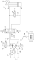
- the hydraulic drive device 1 illustrated in Fig. 1 is included, for example, in a work vehicle (not illustrated in the drawings).
- the work vehicle include construction vehicles such as hydraulic excavators and hydraulic cranes and industrial vehicles such as forklifts.
- the work vehicle is a hydraulic excavator.
- the hydraulic excavator includes a boom, an arm, and an attachment (for example, a bucket).
- the hydraulic excavator can perform various tasks by moving the boom, the arm, and the attachment (for example, the bucket).
- the hydraulic excavator includes a boom cylinder 2.
- the boom cylinder 2 which is one example of the hydraulic cylinder, includes a head-end port 2a and a rod-end port 2b.
- the boom cylinder 2 is provided on the boom.
- the boom cylinder 2 is extended and retracted to move the boom.
- the boom cylinder 2 is driven when the working fluid (for example, liquid such as oil or water) is supplied and drained to and from each of the head-end port 2a and the rod-end port 2b. More specifically, the boom cylinder 2 is extended when the working fluid is supplied to the head-end port 2a and drained from the rod-end port 2b. As a result, the boom moves upward.
- the working fluid for example, liquid such as oil or water
- the boom cylinder 2 is retracted when the working fluid is drained from the head-end port 2a and supplied to the rod-end port 2b. As a result, the boom moves downward. Note that the boom cylinder 2 is under the empty weight of the boom in a retracting direction in the present embodiment. Therefore, the boom cylinder 2 under the empty weight of the boom causes the working fluid to be drained from the head-end port 2a and draws in the working fluid through the rod-end port 2b; thus, the boom cylinder 2 is retracted.
- the hydraulic drive device 1 supplies and drains the working fluid to and from each of the head-end port 2a and the rod-end port 2b.
- the hydraulic drive device 1 drives the boom cylinder 2.
- the hydraulic drive device 1 extends and retracts the boom cylinder 2.
- the hydraulic drive device 1 regenerates energy using the working fluid that is drained from the head-end port 2a of the boom cylinder 2.
- the hydraulic drive device 1 that functions as just described includes a hydraulic pump motor 11, an electric motor 12, a directional control valve 13, a regeneration valve 14, and an unloader valve 15.
- the hydraulic drive device 1 includes an operation device 16, a temperature sensor 17, a stroke sensor 18, and a control device 19.
- the hydraulic pump motor 11 includes a suction port 11a and a discharge port 11b.
- the hydraulic pump motor 11 further includes a shaft 11c.
- the suction port 11a is connected to a tank 20 via a suction passage 21.
- a check valve 24 is interposed in the suction passage 21. The check valve 24 allows the flow of the working fluid from the tank 20 to the suction port 11a and blocks the opposite flow of the working fluid.
- the hydraulic pump motor 11 When the shaft 11c is rotatably driven, the hydraulic pump motor 11 operates as follows. Specifically, the hydraulic pump motor 11 draws in the working fluid through the suction port 11a. Furthermore, the first hydraulic pump motor 11 discharges the working fluid from the discharge port 11b. On the other hand, when the working fluid is supplied to the suction port 11a, the hydraulic pump motor 11 causes rotation of the shaft 11c. Subsequently, the hydraulic pump motor 11 discharges the working fluid from the discharge port 11b.
- the hydraulic pump motor 11, which is a swash plate pump of the variable capacity type includes a regulator 11d. The regulator 11d changes the tilt angle of the swash plate on the basis of a capacity command that is input to the regulator 11d. As a result, the piston capacity of the hydraulic pump motor 11 changes. This means that the hydraulic pump motor 11 can change a discharge flow rate and a suction flow rate.
- the electric motor 12 is connected to the hydraulic pump motor 11. More specifically, the electric motor 12 is coupled to the shaft 11c.
- the electric motor 12 rotatably drives the hydraulic pump motor 11 to discharge the working fluid from the hydraulic pump motor 11. More specifically, the electric motor 12 rotatably drives the shaft 11c to discharge the working fluid from the discharge port 11b.
- the electric motor 12 generates electric power by rotation of the hydraulic pump motor 11 (more specifically, the shaft 11c) when supplied with the working fluid. In other words, the electric motor 12 works with the hydraulic pump motor 11 to regenerate the fluid energy of the working fluid as electrical energy.
- the electric motor 12 changes the rotational speed (more specifically, the rotational speed of the shaft 11c) according to a rotational speed command that is input to the electric motor 12.
- the directional control valve 13 switches the direction of the working fluid flowing between the hydraulic pump motor 11 and the head-end port 2a.
- the directional control valve 13 is connected to each of the suction port 11a and the discharge port 11b of the hydraulic pump motor 11. More specifically, the directional control valve 13 is connected on the side of the suction port 11a of the hydraulic pump motor 11 with respect to the check valve 24 in the suction passage 21. Furthermore, the directional control valve 13 is connected to the discharge port 11b via a discharge passage 22. Furthermore, the directional control valve 13 is connected to the head-end port 2a of the boom cylinder 2. Moreover, the directional control valve 13 is connected to the rod-end port 2b of the boom cylinder 2 and the tank 20.
- the directional control valve 13 switches the connection target of the head-end port 2a between the discharge port 11b and the suction port 11a according to an operation command that is input to the directional control valve 13. Furthermore, when connecting the head-end port 2a to the discharge port 11b, the directional control valve 13 connects the rod-end port 2b to the tank 20. On the other hand, when connecting the head-end port 2a to the suction port 11a, the directional control valve 13 connects the rod-end port 2b to the discharge port 11b. Note that when connecting the rod-end port 2b to the discharge port 11b, the directional control valve 13 allows the flow of the working fluid from the discharge port 11b to the rod-end port 2b and blocks the opposite flow of the working fluid.
- the directional control valve 13 controls the opening degree between the head-end port 2a and the suction port 11a (hereinafter also referred to as "the opening degree of the directional control valve 13") according to the operation command.
- the directional control valve 13 is an electric spool valve. Note that the directional control valve 13 is not limited to the electric spool valve.
- the regeneration valve 14 opens and closes a regeneration passage 23 connecting the head-end port 2a and the rod-end port 2b.
- the regeneration valve 14 is interposed in the regeneration passage 23.
- the regeneration valve 14 opens and closes the regeneration passage 23 according to a regeneration command.
- the regeneration valve 14 allows the flow of the working fluid in a regeneration direction and blocks the opposite flow of the working fluid.
- the regeneration direction refers to the direction of the flow from the head-end port 2a to the rod-end port 2b.
- the regeneration valve 14 regenerates, to the rod-end port 2b, the working fluid drained from the head-end port 2a.
- the regeneration valve 14 reduces the opening degree according to the regeneration command.
- the regeneration valve 14 is an electromagnetic proportional control valve, for example.
- the unloader valve 15 connects, to the tank 20, the discharge passage 22 connecting the discharge port 11b and the directional control valve 13. More specifically, the unloader valve 15 connects the discharge passage 22 to the tank 20 according to an unloading command that is input to the unloader valve 15.
- the hydraulic pump motor 11 can be unloaded.
- the unloader valve 15 is a solenoid on-off valve.
- the unloader valve 15 may be an electromagnetic proportional control valve having a controllable opening degree.
- the operation device 16 is for operating the boom (more specifically, the boom cylinder 2).
- the operation device 16 includes an operation lever 16a.
- the operation lever 16a is configured to be operable.
- the operation device 16 outputs an operation signal corresponding to an operation direction and an operation amount of the operation lever 16a.
- the operation device 16 is an electric joystick, for example.
- the operation device 16 may be a pilot operation valve. In this case, the operation device 16 outputs an operation signal corresponding to the output pressure of the pilot operation valve.
- the operation device 16 may be a touch panel. In this case, the operation device 16 outputs an operation signal according to an operation that is input thereto, a program, or the like.
- the temperature sensor 17 measures the coil temperature of the electric motor 12. More specifically, the temperature sensor 17 directly or indirectly measures the coil temperature of the electric motor 12. In the present embodiment, the temperature sensor 17 is provided on the casing of the electric motor 12. The temperature sensor 17 indirectly measures the coil temperature by measuring the temperature of the casing of the electric motor 12. Furthermore, the temperature sensor 17 outputs the measured temperature of the casing of the electric motor 12.
- the stroke sensor 18, which is one example of the speed-related sensor, is a sensor for measuring the speed of the boom cylinder 2. More specifically, the stroke sensor 18 measures the stroke length of the boom cylinder 2. Subsequently, the stroke sensor 18 outputs the measured stroke length.
- the speed-related sensor may be a speed sensor, an acceleration sensor, an angle sensor, and an inertial measurement unit (abbreviated as IMU); it is sufficient that the speed-related sensor be a sensor capable of calculating the speed of the boom cylinder 2 on the basis of other measurement results.
- the speed sensor measures the speed of the stroke of the boom cylinder 2.
- the acceleration sensor measures the acceleration of the stroke of the boom cylinder 2.
- the angle sensor measures the angle of the boom.
- the IMU measures the acceleration and the rotational speed of the boom.
- the control device 19 controls the operation of each of the directional control valve 13, the regeneration valve 14, and the unloader valve 15 according to the operation signal that is input to the control device 19. More specifically, the control device 19 outputs the operation command, the regeneration command, and the unloading command each of which corresponds to the operation signal, thereby controlling the operations of the directional control valve 13, the regeneration valve 14, and the unloader valve 15. Thus, the control device 19 controls the flow of the working fluid in the hydraulic drive device 1. Furthermore, the control device 19 controls the operation of each of the hydraulic pump motor 11 and the electric motor 12 according to the operation signal. More specifically, the control device 19 outputs the capacity command and the rotational speed command each of which corresponds to the operation signal, thereby controlling the operations of the hydraulic pump motor 11 and the electric motor 12. Thus, the control device 19 controls the discharge flow rate and the suction flow rate at the hydraulic pump motor 11.
- control device 19 changes the discharge flow rate and the suction flow rate at the hydraulic pump motor 11 according to the measurement result of the stroke sensor 18 in the present embodiment.
- the control device 19 performs the feedback control of the speed or the acceleration (in the present embodiment, the speed) of the boom cylinder 2.
- control device 19 controls the operation of each of the directional control valve 13 and the regeneration valve 14 on the basis of the coil temperature measured by the temperature sensor 17. More specifically, the control device 19 controls the opening degree of each of the directional control valve 13 and the regeneration valve 14 on the basis of the coil temperature measured by the temperature sensor 17.
- the operation device 16 when the operation device 16 is operated (in the present embodiment, when the operation lever 16a is operated), the operation device 16 outputs the operation signal.
- the control device 19 controls the operation of each of the directional control valve 13, the regeneration valve 14, and the unloader valve 15 according to the operation signal. Furthermore, the control device 19 controls the operation of each of the electric motor 12 and the hydraulic pump motor 11 according to the operation signal and the measurement result of the stroke sensor 18. Thus, the control device 19 extends and retracts the boom cylinder 2 in a direction and at a speed that correspond to the operation signal (in the present embodiment, the operation direction and the operation amount of the operation lever 16a).
- the hydraulic drive device 1 when lowering the boom (in other words, when retracting the boom cylinder 2), part of the working fluid drained from the head-end port 2a of the boom cylinder 2 is regenerated to the rod-end port 2b of the boom cylinder 2. Furthermore, in the hydraulic drive device 1, the remaining part of the working fluid drained from the head-end port 2a is used for energy regeneration. Moreover, the control device 19 controls the opening degree of each of the directional control valve 13 and the regeneration valve 14 on the basis of the coil temperature of the electric motor 12. This prevents an excessive increase in the coil temperature of the electric motor 12.
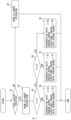
- Step S1 which is a boom lowering operation determination step
- the control device 19 determines whether the operation performed on the operation device 16 is a boom lowering operation (that is, an operation to retract the boom cylinder 2). More specifically, the control device 19 detects an operation direction of the operation lever 16a on the basis of the operation signal.
- the control device 19 determines whether the operation performed is the boom lowering operation. For example, when the operation lever 16a is operated in a first direction, the control device 19 determines that the operation performed is a boom raising operation. As a result, the processing transitions to Step S2. On the other hand, when the operation lever 16a is operated in a second direction, the control device 19 determines that the operation performed is a boom lowering operation. As a result, the processing transitions to Step S3.
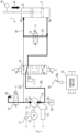
- Step S2 which is a boom cylinder extension step, the control device 19 extends the boom cylinder 2. More specifically, the control device 19 operates the directional control valve 13 according to the operation signal. For example, the control device 19 outputs the operation command corresponding to the operation signal to the directional control valve 13. Accordingly, the directional control valve 13 connects the discharge port 11b to the head-end port 2a and connects the rod-end port 2b to the tank 20, as illustrated in Fig. 3 . Note that in the directional control valve 13, the opening degree between the discharge port 11b and the head-end port 2a is a full opening degree in the present embodiment. Meanwhile, the directional control valve 13 cuts off the suction port 11a from the head-end port 2a and the rod-end port 2b.
- the control device 19 outputs the rotational speed command and the capacity command that correspond to the operation signal.
- the hydraulic pump motor 11 discharges the working fluid from the discharge port 11b at a flow rate corresponding to the operation signal.
- the working fluid discharged is brought to the head-end port 2a via the directional control valve 13 (the arrow A1 in Fig. 3 ).
- the working fluid is drained from the rod-end port 2b to the tank 20 via the directional control valve 13 (the arrow A2 in Fig. 3 ).
- the boom cylinder 2 is extended at a speed corresponding to the operation signal (refer to the arrow A and the dash-dot-dot line in Fig. 3 ).
- the boom can be raised at a speed corresponding to the operation signal.
- the control device 19 ends the boom cylinder extraction and retraction process.
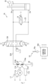
- Step S3 which is a boom cylinder retraction step, the control device 19 retracts the boom cylinder 2. More specifically, the control device 19 operates the directional control valve 13, the regeneration valve 14, and the unloader valve 15 according to the operation signal. For example, the control device 19 outputs the operation command corresponding to the operation signal to the directional control valve 13. Accordingly, the control device 19 causes the directional control valve 13 to connect the head-end port 2a to the suction port 11a, as illustrated in Fig. 4 . Furthermore, the control device 19 outputs the regeneration command to the regeneration valve 14. Accordingly, the control device 19 causes the regeneration valve 14 to open the regeneration passage 23. As a result, the head-end port 2a and the rod-end port 2b are placed in communication. Moreover, the control device 19 outputs the unloading command to the unloader valve 15. Accordingly, the control device 19 causes the unloader valve 15 to connect the discharge passage 22 to the tank 20. As a result, the hydraulic pump motor 11 is unloaded.
- the working fluid flows as follows. Specifically, the boom cylinder 2 is under the empty weight of the boom in the retracting direction. Therefore, the boom cylinder 2 is retracted under the empty weight of the boom. Thus, the working fluid is drained from the head-end port 2a. Part of the working fluid drained is supplied to the rod-end port 2b through the regeneration passage 23. In other words, part of the working fluid is regenerated from the head-end port 2a to the rod-end port 2b (refer to the arrow B1 in Fig. 4 ).
- the remaining part is supplied to the suction port 11a of the hydraulic pump motor 11 via the directional control valve 13 (refer to the arrow B2 in Fig. 4 ). Subsequently, the remaining part rotatably drives the electric motor 12 via the hydraulic pump motor 11 and then is drained from the discharge port 11b to the tank 20 via the unloader valve 15.
- the electric motor 12 When the electric motor 12 is rotatably driven, the electric motor 12 generates electric power.
- the fluid energy of the remaining part is regenerated as electrical energy.
- the potential energy of the boom is regenerated as electrical energy.
- energy can be regenerated using the working fluid drained.
- the control device 19 retracts the boom cylinder 2 at a speed corresponding to the operation signal. More specifically, the control device 19 outputs the rotational speed command and the capacity command that correspond to the operation signal. Accordingly, the hydraulic pump motor 11 can cause the working fluid to flow into the suction port 11a at a flow rate corresponding to the operation signal; thus, the flow rate of the working fluid that is drained from the head-end port 2a of the boom cylinder 2 can be controlled and set to the flow rate corresponding to the operation signal.
- the flow rate of the working fluid that is regenerated to the rod-end port 2b can be controlled and set to the flow rate corresponding to the operation signal and therefore, the boom cylinder 2 can be retracted at a speed corresponding to the operation signal (refer to the arrow B and the dash-dot-dot line in Fig. 4 ).
- the boom can be lowered at a speed corresponding to the operation signal.
- control device 19 performs the following feedback control in the boom lowering operation. Specifically, the control device 19 changes the suction flow rate at the hydraulic pump motor 11 according to the measurement result of the stroke sensor 18. More specifically, the control device 19 changes the suction flow rate at the hydraulic pump motor 11 by outputting the capacity command and the rotational speed command according to the measurement result of the stroke sensor 18. In this manner, the control device 19 performs the feedback control of the speed of the boom cylinder 2. This leads to a reduced occurrence of hunting in the boom cylinder 2.
- Step S4 which is a first coil temperature determination step, the control device 19 determines whether a coil temperature T of the electric motor 12 is higher than or equal to a first predetermined temperature T1. More specifically, the control device 19 estimates the coil temperature T on the basis of the temperature of the casing measured by the temperature sensor 17. Subsequently, the control device 19 determines whether the coil temperature T is higher than or equal to the first predetermined temperature T1. When the coil temperature T is lower than the first predetermined temperature T1, the processing proceeds to Step S5. On the other hand, when the coil temperature T is higher than or equal to the first predetermined temperature T1, the processing proceeds to Step S6.
- Step S5 which is a first opening degree control step, the control device 19 controls the opening degree of the regeneration valve 14 according to the coil temperature T. More specifically, the control device 19 sets an opening degree R of the regeneration valve 14 to at least a predetermined first regeneration opening degree R1, for example, a full opening degree. Furthermore, the control device 19 sets the opening degree between the head-end port 2a and the suction port 11a, that is, an opening degree D of the directional control valve 13, to at least a predetermined first regeneration opening degree D1, for example, a full opening degree.
- each of the first regeneration opening degree R1 and the first regeneration opening degree D1 does not necessarily need to be the full opening degree; it is sufficient that each of the first regeneration opening degree R1 and the first regeneration opening degree D1 be at least 85% of the full opening degree. Subsequently, when the boom lowering operation ends, the control device 19 ends the boom cylinder extraction and retraction process.
- Step S6 which is a second coil temperature determination step, the control device 19 determines whether the coil temperature T of the electric motor 12 is higher than or equal to a second predetermined temperature T2. More specifically, the control device 19 determines whether the coil temperature T estimated in Step S4 is higher than or equal to the second predetermined temperature T2 (> the first predetermined temperature T1). When the coil temperature T is lower than the second predetermined temperature T2, the processing proceeds to Step S7. On the other hand, when the coil temperature T is higher than or equal to the second predetermined temperature T2, the processing proceeds to Step S8.
- Step S7 which is a second opening degree control step, the control device 19 reduces the opening degree of the regeneration valve 14. More specifically, the control device 19 reduces the opening degree R of the regeneration valve 14 from the first regeneration opening degree R1. In other words, the control device 19 reduces the opening degree R of the regeneration valve 14 to a second regeneration opening degree R2 (an opening degree that is, for example, 50% or more and less than 85% of the opening degree in the fully open state). As a result, a pressure loss occurs in the working fluid flowing in the hydraulic drive device 1. Therefore, the fluid energy of the working fluid to be supplied to the hydraulic pump motor 11 can be reduced.
- the second regeneration opening degree R2 is not limited to the aforementioned numerical range; it is sufficient that the second regeneration opening degree R2 be less than the first regeneration opening degree R1.
- the control device 19 reduces the opening degree of the directional control valve 13. More specifically, the control device 19 reduces the opening degree D of the directional control valve 13 from the first regeneration opening degree D1. In other words, the control device 19 reduces the opening degree D of the directional control valve 13 to a second regeneration opening degree D2 (an opening degree that is, for example, 50% or more and less than 85% of the opening degree in the fully open state).
- a second regeneration opening degree D2 an opening degree that is, for example, 50% or more and less than 85% of the opening degree in the fully open state.
- the second regeneration opening degree D2 is not limited to the aforementioned numerical range; it is sufficient that the second regeneration opening degree D2 be less than the first regeneration opening degree D1.
- the fluid energy of the working fluid is reduced using the regeneration valve 14 and the directional control valve 13.
- This allows for a reduction in energy to be regenerated using the electric motor 12.
- the control device 19 ends the boom cylinder extraction and retraction process when the boom lowering operation ends.
- Step S8 which is a third opening degree control step, the control device 19 further reduces the opening degree of the regeneration valve 14. More specifically, the control device 19 reduces the opening degree R of the regeneration valve 14 to a regeneration lower limit value RU.
- the regeneration lower limit value RU is the lower limit value of the opening degree R during regeneration.
- the regeneration lower limit value RU is an opening degree that is approximately 50% of the opening degree in the fully open state.
- the regeneration lower limit value RU is not limited to the aforementioned numerical range; it is sufficient that the regeneration lower limit value RU be an opening degree that is 20% or more and less than 50% of the opening degree in the fully open state.
- control device 19 further reduces the opening degree of the directional control valve 13. More specifically, the control device 19 causes the directional control valve 13 to reduce the opening degree D of the directional control valve 13 to a regeneration lower limit value DU.
- the regeneration lower limit value DU is the lower limit value of the opening degree D during regeneration.
- the regeneration lower limit value DU is an opening degree that is approximately 50% of the opening degree in the fully open state. Note that the regeneration lower limit value DU is not limited to the aforementioned numerical range; it is sufficient that the regeneration lower limit value DU be an opening degree that is 20% or more and less than 50% of the opening degree in the fully open state.
- the fluid energy of the working fluid is further reduced using the regeneration valve 14 and the directional control valve 13.
- This allows for a further reduction in energy to be regenerated using the electric motor 12.
- it is possible to further prevent an excessive increase in the coil temperature of the electric motor 12.
- control device 19 controls the pump capacity of the hydraulic pump motor 11 and the rotational speed of the electric motor 12 according to the coil temperature during regeneration. More specifically, according to the estimated coil temperature, the control device 19 limits the capacity command and the rotational speed command to be output. Thus, each of the pump capacity of the hydraulic pump motor 11 and the rotational speed of the electric motor 12 is limited. As a result, the suction flow rate at the hydraulic pump motor 11 can be reduced. This allows for a reduction in the amount of energy to be regenerated using the electric motor 12 during regeneration. Therefore, it is possible to prevent an excessive increase in the coil temperature.
- the opening degree of the regeneration valve 14 is controlled according to the coil temperature. Therefore, it is possible to cause an energy loss at the regeneration valve 14 before the coil temperature increases excessively by energy regeneration. This prevents an excessive increase in the coil temperature of the electric motor 12.
- the control device 19 when the coil temperature T is higher than or equal to the first predetermined temperature T1, the control device 19 reduces the opening degree R of the regeneration valve 14. Therefore, it is possible to cause an energy loss during regeneration. Accordingly, it is possible to reduce the load on the coil during regeneration. Thus, the increase in the coil temperature is reduced.
- the opening degree of the regeneration valve 14 when the coil temperature T is lower than the first predetermined temperature T1, the opening degree of the regeneration valve 14 remains large, making it possible to reduce the energy loss during regeneration. Thus, the regeneration efficiency in the hydraulic drive device 1 can be maintained at a high level.
- the control device 19 when the coil temperature is higher than or equal to the predetermined value, the control device 19 reduces the opening degree of the directional control valve 13. Therefore, it is possible to cause a pressure loss. This allows for a reduction in the load on the electric motor 12 during regeneration. Thus, the increase in the coil temperature is reduced. On the other hand, when the coil temperature is lower than the predetermined value, the opening degree of the directional control valve 13 remains large, making it possible to reduce the pressure loss during regeneration. Thus, the regeneration efficiency in the hydraulic drive device 1 can be maintained at a high level.
- the control device 19 controls the rotational speed of the electric motor 12 according to the coil temperature. Therefore, it is possible to reduce the suction flow rate at the hydraulic pump motor 11 by reducing the rotational speed of the electric motor 12. Accordingly, it is possible to reduce the amount of energy regeneration in the electric motor 12; thus, the increase in the coil temperature is reduced.
- the control device 19 controls the pump capacity of the hydraulic pump motor 11 according to the coil temperature. Therefore, it is possible to reduce the suction flow rate at the hydraulic pump motor 11 by reducing the pump capacity of the hydraulic pump motor 11. Accordingly, it is possible to reduce the amount of energy regeneration in the electric motor 12; thus, the increase in the coil temperature is reduced.
- the control device 19 actuates the unloader valve 15 when regeneration is performed using the electric motor 12. Therefore, it is possible to reduce the increase in discharge pressure at the hydraulic pump motor 11. Thus, the regeneration efficiency in the electric motor 12 can be maintained at a high level.
- the suction flow rate at the hydraulic pump motor 11 is changed according to the measurement result of the stroke sensor 18, and thus the feedback control of the operation speed or the acceleration of the boom cylinder 2 is performed. Therefore, the occurrence of hunting in the boom cylinder 2 is reduced.
- a hydraulic drive device 1A according to Embodiment 2 is similar in configuration to the hydraulic drive device 1 according to Embodiment 1. Therefore, the configuration of the hydraulic drive device 1A according to Embodiment 2 will be described focusing on differences from the hydraulic drive device 1 according to Embodiment 1; elements that are the same as those of the hydraulic drive device 1 according to Embodiment 1 share the same reference signs, and as such, description of the elements will be omitted.
- the hydraulic drive device 1A includes a hydraulic pump motor 11A, the electric motor 12, a directional control valve 13A, and the regeneration valve 14. Furthermore, the hydraulic drive device 1A includes the operation device 16, the temperature sensor 17, the stroke sensor 18, and a control device 19A.
- the hydraulic pump motor 11A includes a first port 11Aa, a second port 11Ab, and the shaft 11c.
- the first port 11Aa is connected to the tank 20 via a tank passage 21A.
- the second port 11Ab is connected to a pump passage 22A.
- the hydraulic pump motor 11A draws in the working fluid through the first port 11Aa and discharges the working fluid from the second port 11Ab.
- the hydraulic pump motor 11A rotates the shaft 11c backward. Subsequently, the hydraulic pump motor 11A drains the working fluid from the first port 11Aa.
- the hydraulic pump motor 11A which is a swash plate pump of the variable capacity type, includes the regulator 11d.
- the directional control valve 13A switches the direction of the working fluid flowing between the hydraulic pump motor 11A and the head-end port 2a.
- the directional control valve 13A is connected to the second port 11Ab of the hydraulic pump motor 11A via the pump passage 22A. Furthermore, the directional control valve 13A is connected to the head-end port 2a and the rod-end port 2b of the boom cylinder 2. Moreover, the directional control valve 13A is connected to the tank 20.
- the directional control valve 13A When the operation command is input to the directional control valve 13A, the directional control valve 13A connects the second port 11Ab to the head-end port 2a. Furthermore, the directional control valve 13A opens and closes the path between the rod-end port 2b and the tank 20 according to the operation command that is input to the directional control valve 13A. Thus, the directional control valve 13A can switch the direction of the working fluid flowing between the hydraulic pump motor 11A and the head-end port 2a. When causing the working fluid to flow from the head-end port 2a to the second port 11Ab, the directional control valve 13A controls the opening degree between the head-end port 2a and the second port 11Ab (that is, the opening degree of the directional control valve 13A) according to the operation command.
- the directional control valve 13A is an electric spool valve. Note that the directional control valve 13A is not limited to the electric spool valve.
- the control device 19A controls the operation of each of the directional control valve 13A, the regeneration valve 14, and the unloader valve 15 according to an operation signal that is input to the control device 19A, as with the control device 19 according to Embodiment 1. Furthermore, the control device 19A changes the discharge flow rate and the suction flow rate at the hydraulic pump motor 11A according to the measurement result of the stroke sensor 18 in the present embodiment. Furthermore, the control device 19A controls the opening degree of each of the directional control valve 13A and the regeneration valve 14 according to the suction pressure measured by the temperature sensor 17.
- the boom cylinder extension and retraction process is performed as in the hydraulic drive device 1 according to Embodiment 1.
- the boom cylinder extension and retraction process performed by the control device 19A is similar to the boom cylinder extension and retraction process performed by the control device 19 according to Embodiment 1.
- the boom cylinder extension and retraction process performed by the control device 19A will be described focusing on differences from the boom cylinder extension and retraction process performed by the control device 19 according to Embodiment 1.
- Step S2 which is the boom cylinder extension step
- the control device 19A extends the boom cylinder 2. More specifically, the control device 19A operates the directional control valve 13A according to the operation signal. For example, the control device 19A outputs the operation command corresponding to the operation signal to the directional control valve 13A. Accordingly, the directional control valve 13A connects the second port 11Ab to the head-end port 2a and connects the rod-end port 2b to the tank 20. Furthermore, the control device 19A outputs the rotational speed command and the capacity command that correspond to the operation signal. As a result, the hydraulic pump motor 11A discharges the working fluid from the second port 11Ab at a flow rate corresponding to the operation signal. Thus, the boom can be raised at a speed corresponding to the operation signal. Subsequently, when the boom raising operation ends, the control device 19A ends the boom cylinder extraction and retraction process.
- Step S3 which is the boom cylinder retraction step, the control device 19A retracts the boom cylinder 2. More specifically, the control device 19A operates the directional control valve 13A and the regeneration valve 14 according to the operation signal. For example, the control device 19A outputs the operation command corresponding to the operation signal to the directional control valve 13A. Thus, the control device 19A causes the directional control valve 13A to connect the head-end port 2a to the second port 11Ab and cuts off the path between the rod-end port 2b and the tank 20. Furthermore, the control device 19A outputs the regeneration command to the regeneration valve 14, causing the regeneration valve 14 to open the regeneration passage 23.
- the control device 19A controls the suction flow rate to retract the boom cylinder 2 at a speed corresponding to the operation signal, and performs the feedback control of the speed or the acceleration of the boom cylinder 2 according to the measurement result of the stroke sensor 18.
- the hydraulic drive device 1A according to the present embodiment produces substantially the same advantageous effects as those produced by the hydraulic drive device 1 according to Embodiment 1.
- the hydraulic cylinder that supplies the working fluid may be hydraulic cylinders other than the boom cylinder 2 such as an arm cylinder and a lift cylinder, for example.
- the directional control valves 13, 13A and the regeneration valve 14 do not necessarily need to both have adjustable opening degrees; it is sufficient that at least one of the directional control valves 13, 13A and the regeneration valve 14 be configured so that the opening degree thereof can be adjusted.
- the control devices 19, 19A do not necessarily need to reduce the opening degrees of both of the directional control valve 13 and the regeneration valve 14. It is sufficient that the control devices 19, 19A reduce the opening degree of at least one of the directional control valve 13 and the regeneration valve 14.
- control devices 19, 19A may selectively reduce the opening degrees of the directional control valves 13, 13A and the regeneration valve 14 according to the coil temperature. For example, according to an increase in the coil temperature, the control devices 19, 19A first reduce the opening degree of the regeneration valve 14, and then reduce the opening degrees of the directional control valves 13, 13A. Furthermore, when the coil temperature increases excessively, the control devices 19, 19A do not necessarily need to limit the pump capacities of the hydraulic pump motors 11, 11A and the rotational speed of the electric motor 12. Moreover, the control devices 19, 19A do not necessarily need to perform the feedback control of the speed of the boom cylinder 2.
- the drive source for the hydraulic pump motors 11, 11A is not limited to the electric motor 12 and may be a hybrid drive source that uses the electric motor 12 and an engine.
- a hydraulic drive device drives a hydraulic cylinder by supplying and draining a working fluid to and from each of a head-end port and a rod-end port of the hydraulic cylinder and includes: a hydraulic pump motor that discharges the working fluid and is rotatably driven by the working fluid supplied to the hydraulic pump motor; an electric motor connected to the hydraulic pump motor; a directional control valve that switches a direction of the working fluid flowing between the hydraulic pump motor and the head-end port; a regeneration valve that opens and closes a regeneration passage connecting the head-end port and the rod-end port; a temperature sensor that measures a coil temperature of the electric motor; and a control device that controls an operation of each of the directional control valve and the regeneration valve.
- the control device controls an opening degree of the regeneration valve according to the coil temperature measured by the temperature sensor when causing the regeneration valve to open the regeneration passage and causing the directional control valve to connect the head-end port and the hydraulic pump motor.
- the opening degree of the regeneration valve is controlled according to the coil temperature. Therefore, it is possible to cause an energy loss at the regeneration valve before the coil temperature increases excessively by energy regeneration. This prevents an excessive increase in the coil temperature of the electric motor.
- the control device may reduce the opening degree of the regeneration valve.
- the control device when the coil temperature is higher than or equal to the predetermined temperature, the control device reduces the opening degree of the regeneration valve. Therefore, it is possible to cause an energy loss during regeneration. Accordingly, it is possible to reduce the load on the coil during regeneration. Thus, the increase in the coil temperature is reduced.
- the opening degree of the regeneration valve remains large, making it possible to reduce the energy loss during regeneration.
- the regeneration efficiency in the hydraulic drive device can be maintained at a high level.
- the control device may cause the directional control valve to reduce an opening degree between the head-end port and the hydraulic pump motor.
- the control device when the coil temperature is higher than or equal to the predetermined value, the control device reduces the opening degree of the directional control valve. Therefore, it is possible to cause a pressure loss. This allows for a reduction in the load on the electric motor during regeneration. Thus, the increase in the coil temperature is reduced. On the other hand, when the coil temperature is lower than the predetermined temperature, the opening degree of the directional control valve remains large, making it possible to reduce the pressure loss during regeneration. Thus, the regeneration efficiency in the hydraulic drive device can be maintained at a high level.
- control device may control a rotational speed of the electric motor according to the coil temperature measured by the temperature sensor.
- the control device controls the rotational speed of the electric motor according to the coil temperature. Therefore, it is possible to reduce the suction flow rate at the hydraulic pump motor by reducing the rotational speed of the electric motor. Accordingly, it is possible to reduce the amount of energy regeneration in the electric motor; thus, the increase in the coil temperature is reduced.
- the control device controls the pump capacity of the hydraulic pump motor according to the coil temperature. Therefore, it is possible to reduce the suction flow rate at the hydraulic pump motor by reducing the pump capacity of the hydraulic pump motor. Accordingly, it is possible to reduce the amount of energy regeneration in the electric motor; thus, the increase in the coil temperature is reduced.
- the hydraulic drive device may further include an unloader valve
- the hydraulic pump motor may include a discharge port through which the working fluid is discharged and a suction port through which the working fluid is drawn in
- the directional control valve may switch a connection target of the head-end port between the discharge port and the suction port
- the unloader valve may connect, to a tank, a discharge passage connecting the discharge port and the directional control valve
- the control device may actuate the unloader valve when causing the directional control valve to connect the head-end port to the suction port.
- control device actuates the unloader valve when regeneration is performed using the electric motor. Therefore, it is possible to reduce the increase in discharge pressure at the hydraulic pump motor. Thus, the regeneration efficiency in the electric motor can be maintained at a high level.
- the hydraulic drive device may further include a speed-related sensor that measures an operation speed of the hydraulic cylinder, and the control device may perform feedback control of the operation speed or an acceleration of the hydraulic cylinder by changing a suction flow rate at the hydraulic pump motor according to a measurement result of the speed-related sensor.
Landscapes
- Engineering & Computer Science (AREA)
- General Engineering & Computer Science (AREA)
- Physics & Mathematics (AREA)
- Fluid Mechanics (AREA)
- Mechanical Engineering (AREA)
- Chemical & Material Sciences (AREA)
- Analytical Chemistry (AREA)
- Mining & Mineral Resources (AREA)
- Civil Engineering (AREA)
- Structural Engineering (AREA)
- Fluid-Pressure Circuits (AREA)
Applications Claiming Priority (2)
| Application Number | Priority Date | Filing Date | Title |
|---|---|---|---|
| JP2022101450A JP7847486B2 (ja) | 2022-06-23 | 2022-06-23 | 液圧駆動装置 |
| PCT/JP2023/019118 WO2023248681A1 (ja) | 2022-06-23 | 2023-05-23 | 液圧駆動装置 |
Publications (2)
| Publication Number | Publication Date |
|---|---|
| EP4545802A1 true EP4545802A1 (de) | 2025-04-30 |
| EP4545802A4 EP4545802A4 (de) | 2026-07-08 |
Family
ID=89379749
Family Applications (1)
| Application Number | Title | Priority Date | Filing Date |
|---|---|---|---|
| EP23826869.2A Pending EP4545802A4 (de) | 2022-06-23 | 2023-05-23 | Hydraulische antriebsvorrichtung |
Country Status (4)
| Country | Link |
|---|---|
| EP (1) | EP4545802A4 (de) |
| JP (1) | JP7847486B2 (de) |
| CN (1) | CN119630891A (de) |
| WO (1) | WO2023248681A1 (de) |
Family Cites Families (14)
| Publication number | Priority date | Publication date | Assignee | Title |
|---|---|---|---|---|
| JP2008157407A (ja) | 2006-12-26 | 2008-07-10 | Hy:Kk | 液圧駆動装置 |
| US20110056194A1 (en) | 2009-09-10 | 2011-03-10 | Bucyrus International, Inc. | Hydraulic system for heavy equipment |
| KR101652112B1 (ko) | 2009-12-23 | 2016-08-29 | 두산인프라코어 주식회사 | 하이브리드 굴삭기 붐 구동시스템 및 그 제어방법 |
| JP5530728B2 (ja) | 2010-01-20 | 2014-06-25 | 株式会社神戸製鋼所 | 油圧制御装置及びこれを備えた油圧式作業機械 |
| JP5515087B2 (ja) * | 2011-06-15 | 2014-06-11 | 日立建機株式会社 | 作業機械の動力回生装置 |
| KR101580933B1 (ko) | 2011-07-06 | 2015-12-30 | 스미도모쥬기가이고교 가부시키가이샤 | 쇼벨 및 쇼벨의 제어방법 |
| JP2013068011A (ja) | 2011-09-22 | 2013-04-18 | Hitachi Constr Mach Co Ltd | 油圧作業機械の駆動装置 |
| WO2013175658A1 (ja) * | 2012-05-23 | 2013-11-28 | 株式会社小松製作所 | ハイブリッド作業機械及びハイブリッド作業機械の制御方法 |
| US9279236B2 (en) | 2012-06-04 | 2016-03-08 | Caterpillar Inc. | Electro-hydraulic system for recovering and reusing potential energy |
| CN104903595B (zh) | 2013-01-08 | 2017-03-08 | 日立建机株式会社 | 工作机械的液压系统 |
| JP6522386B2 (ja) | 2015-03-26 | 2019-05-29 | 住友重機械工業株式会社 | ショベル |
| JP7382792B2 (ja) | 2019-10-31 | 2023-11-17 | 川崎重工業株式会社 | 再生装置、それを備える液圧駆動システム、及びその制御装置 |
| WO2021225645A1 (en) * | 2020-05-05 | 2021-11-11 | Parker-Hannifin Corporation | Hydraulic dissipation of electric power |
| JP7478588B2 (ja) | 2020-05-18 | 2024-05-07 | 川崎重工業株式会社 | 油圧ショベル駆動システム |
-
2022
- 2022-06-23 JP JP2022101450A patent/JP7847486B2/ja active Active
-
2023
- 2023-05-23 EP EP23826869.2A patent/EP4545802A4/de active Pending
- 2023-05-23 WO PCT/JP2023/019118 patent/WO2023248681A1/ja not_active Ceased
- 2023-05-23 CN CN202380049091.5A patent/CN119630891A/zh active Pending
Also Published As
| Publication number | Publication date |
|---|---|
| CN119630891A (zh) | 2025-03-14 |
| US20260022712A1 (en) | 2026-01-22 |
| JP2024002330A (ja) | 2024-01-11 |
| JP7847486B2 (ja) | 2026-04-17 |
| WO2023248681A1 (ja) | 2023-12-28 |
| EP4545802A4 (de) | 2026-07-08 |
Similar Documents
| Publication | Publication Date | Title |
|---|---|---|
| US10184225B2 (en) | Working machine | |
| KR101121705B1 (ko) | 건설기계의 붐 위치에너지 회생 장치 및 방법 | |
| CN104093994B (zh) | 液压驱动系统 | |
| EP2730704B1 (de) | Regenerativer hydraulikkreis für einen bagger and steuerungsverfahren für den bagger | |
| CN104619996B (zh) | 电动式液压作业机械的液压驱动装置 | |
| US9702118B2 (en) | Hydraulic regenerative and recovery parasitic mitigation system | |
| EP2857696A1 (de) | Hydraulisches geschlossenes umlaufsystem | |
| US9995018B2 (en) | Control system of hybrid construction machine | |
| US20160312443A1 (en) | Control system of hybrid construction machine | |
| WO2012166224A2 (en) | Hydraulic control system having cylinder stall strategy | |
| WO2012166225A2 (en) | Hydraulic control system having cylinder stall strategy | |
| CN110177952A (zh) | 建设机械 | |
| EP4545808A1 (de) | Hydraulische antriebsvorrichtung | |
| US20260022712A1 (en) | Hydraulic drive device | |
| EP4549746A1 (de) | Hydraulische antriebsvorrichtung | |
| EP4545809A1 (de) | Hydraulische antriebsvorrichtung | |
| US20250382980A1 (en) | Hydraulic drive device | |
| JP2008185098A (ja) | 作業機械における制御システム | |
| CN113544389B (zh) | 作业机械 | |
| JP2008185099A (ja) | 作業機械における制御システム | |
| JP2013044399A (ja) | 油圧駆動システム |
Legal Events
| Date | Code | Title | Description |
|---|---|---|---|
| STAA | Information on the status of an ep patent application or granted ep patent |
Free format text: STATUS: THE INTERNATIONAL PUBLICATION HAS BEEN MADE |
|
| PUAI | Public reference made under article 153(3) epc to a published international application that has entered the european phase |
Free format text: ORIGINAL CODE: 0009012 |
|
| STAA | Information on the status of an ep patent application or granted ep patent |
Free format text: STATUS: REQUEST FOR EXAMINATION WAS MADE |
|
| 17P | Request for examination filed |
Effective date: 20250123 |
|
| AK | Designated contracting states |
Kind code of ref document: A1 Designated state(s): AL AT BE BG CH CY CZ DE DK EE ES FI FR GB GR HR HU IE IS IT LI LT LU LV MC ME MK MT NL NO PL PT RO RS SE SI SK SM TR |
|
| DAV | Request for validation of the european patent (deleted) | ||
| DAX | Request for extension of the european patent (deleted) | ||
| A4 | Supplementary search report drawn up and despatched |
Effective date: 20260610 |
|
| RIC1 | Information provided on ipc code assigned before grant |
Ipc: F15B 11/024 20060101AFI20260603BHEP Ipc: F15B 11/00 20060101ALI20260603BHEP Ipc: F15B 21/14 20060101ALI20260603BHEP Ipc: E02F 9/20 20060101ALI20260603BHEP Ipc: E02F 9/22 20060101ALI20260603BHEP Ipc: E02F 9/24 20060101ALI20260603BHEP Ipc: F15B 21/08 20060101ALI20260603BHEP Ipc: F15B 11/042 20060101ALI20260603BHEP |