EP4545733A2 - Bathhouse - Google Patents
Bathhouse Download PDFInfo
- Publication number
- EP4545733A2 EP4545733A2 EP25164654.3A EP25164654A EP4545733A2 EP 4545733 A2 EP4545733 A2 EP 4545733A2 EP 25164654 A EP25164654 A EP 25164654A EP 4545733 A2 EP4545733 A2 EP 4545733A2
- Authority
- EP
- European Patent Office
- Prior art keywords
- building
- bathhouse
- internal
- external
- internal building
- Prior art date
- Legal status (The legal status is an assumption and is not a legal conclusion. Google has not performed a legal analysis and makes no representation as to the accuracy of the status listed.)
- Withdrawn
Links
Images


Classifications
-
- E—FIXED CONSTRUCTIONS
- E04—BUILDING
- E04H—BUILDINGS OR LIKE STRUCTURES FOR PARTICULAR PURPOSES; SWIMMING OR SPLASH BATHS OR POOLS; MASTS; FENCING; TENTS OR CANOPIES, IN GENERAL
- E04H3/00—Buildings or groups of buildings for public or similar purposes; Institutions, e.g. infirmaries or prisons
- E04H3/10—Buildings or groups of buildings for public or similar purposes; Institutions, e.g. infirmaries or prisons for meetings, entertainments, or sports
- E04H3/14—Gymnasiums; Other sporting buildings
- E04H3/16—Gymnasiums; Other sporting buildings for swimming
-
- A—HUMAN NECESSITIES
- A61—MEDICAL OR VETERINARY SCIENCE; HYGIENE
- A61H—PHYSICAL THERAPY APPARATUS, e.g. DEVICES FOR LOCATING OR STIMULATING REFLEX POINTS IN THE BODY; ARTIFICIAL RESPIRATION; MASSAGE; BATHING DEVICES FOR SPECIAL THERAPEUTIC OR HYGIENIC PURPOSES OR SPECIFIC PARTS OF THE BODY
- A61H33/00—Bathing devices for special therapeutic or hygienic purposes
- A61H33/0087—Therapeutic baths with agitated or circulated water
-
- A—HUMAN NECESSITIES
- A61—MEDICAL OR VETERINARY SCIENCE; HYGIENE
- A61H—PHYSICAL THERAPY APPARATUS, e.g. DEVICES FOR LOCATING OR STIMULATING REFLEX POINTS IN THE BODY; ARTIFICIAL RESPIRATION; MASSAGE; BATHING DEVICES FOR SPECIAL THERAPEUTIC OR HYGIENIC PURPOSES OR SPECIFIC PARTS OF THE BODY
- A61H33/00—Bathing devices for special therapeutic or hygienic purposes
- A61H33/06—Artificial hot-air or cold-air baths; Steam or gas baths or douches, e.g. sauna or Finnish baths
-
- A—HUMAN NECESSITIES
- A61—MEDICAL OR VETERINARY SCIENCE; HYGIENE
- A61H—PHYSICAL THERAPY APPARATUS, e.g. DEVICES FOR LOCATING OR STIMULATING REFLEX POINTS IN THE BODY; ARTIFICIAL RESPIRATION; MASSAGE; BATHING DEVICES FOR SPECIAL THERAPEUTIC OR HYGIENIC PURPOSES OR SPECIFIC PARTS OF THE BODY
- A61H33/00—Bathing devices for special therapeutic or hygienic purposes
- A61H33/06—Artificial hot-air or cold-air baths; Steam or gas baths or douches, e.g. sauna or Finnish baths
- A61H33/063—Heaters specifically designed therefor
-
- A—HUMAN NECESSITIES
- A61—MEDICAL OR VETERINARY SCIENCE; HYGIENE
- A61H—PHYSICAL THERAPY APPARATUS, e.g. DEVICES FOR LOCATING OR STIMULATING REFLEX POINTS IN THE BODY; ARTIFICIAL RESPIRATION; MASSAGE; BATHING DEVICES FOR SPECIAL THERAPEUTIC OR HYGIENIC PURPOSES OR SPECIFIC PARTS OF THE BODY
- A61H33/00—Bathing devices for special therapeutic or hygienic purposes
- A61H33/14—Devices for gas baths with ozone, hydrogen, or the like
-
- A—HUMAN NECESSITIES
- A61—MEDICAL OR VETERINARY SCIENCE; HYGIENE
- A61H—PHYSICAL THERAPY APPARATUS, e.g. DEVICES FOR LOCATING OR STIMULATING REFLEX POINTS IN THE BODY; ARTIFICIAL RESPIRATION; MASSAGE; BATHING DEVICES FOR SPECIAL THERAPEUTIC OR HYGIENIC PURPOSES OR SPECIFIC PARTS OF THE BODY
- A61H33/00—Bathing devices for special therapeutic or hygienic purposes
- A61H33/06—Artificial hot-air or cold-air baths; Steam or gas baths or douches, e.g. sauna or Finnish baths
- A61H2033/061—Artificial hot-air baths
-
- A—HUMAN NECESSITIES
- A61—MEDICAL OR VETERINARY SCIENCE; HYGIENE
- A61H—PHYSICAL THERAPY APPARATUS, e.g. DEVICES FOR LOCATING OR STIMULATING REFLEX POINTS IN THE BODY; ARTIFICIAL RESPIRATION; MASSAGE; BATHING DEVICES FOR SPECIAL THERAPEUTIC OR HYGIENIC PURPOSES OR SPECIFIC PARTS OF THE BODY
- A61H2201/00—Characteristics of apparatus not provided for in the preceding codes
- A61H2201/01—Constructive details
- A61H2201/0119—Support for the device
- A61H2201/0126—Support for the device on a wall
Definitions
- the invention relates to a bathhouse and a method of building a bathhouse.
- Chlorine is added to keep the bath water clean from bacteria and contaminants. Chlorine compounds in combination with the moist air create a very corrosive climate which mainly attacks metals.
- high demands are placed on choice of material and the design of both the house structure and the installations of peripherals and furnishings of the bathhouse. For example, electronics, illuminators, channelization for ventilation, electricity and heating installations, etc., are subjected to corrosive attacks.
- the choice of material and the design of the house structure are largely determined by the bath climate.
- An objective with the invention is to provide a bathhouse which can be built in a rational and cost effective way with reduced climate impact.
- a bathhouse comprising an internal building which encloses and shields a wet environment and an external building which encloses the internal building, wherein the walls of the internal building and the walls of the external building are arranged at a distance from each other such that a space is formed between the internal building and the external building.
- the invention is based on the insight that such a bathhouse has great advantages since the climatic barrier which shields the bath can be separated from the climate barrier which shields against the outdoor climate.
- the space formed between the internal building and the external building may have standard indoor climate. This means that the temperature gradient across the climate barrier which shields the bath can be considerably reduced in comparison with outer walls and roof of a traditional bathhouse.
- Such a bathhouse has great advantages since the climate barrier which shields the bath can be separated from the climate barrier which shields adjacent dry rooms.
- the risk of leakage of air and vapor into adjacent dry rooms, and problem with moisture and corrosion resulting therefrom, can be eliminated or at least substantially reduced.
- the space formed between the internal building and the external building can be ventilated for removing any leakage from the internal building. In this way, traditional building technology and materials can be used for an adjacent building providing the dry rooms outside the external building.
- the roof of the internal building and the roof of the external building are suitably arranged at a distance from each other such that the space formed between the internal building and the external building extends around and over the internal building.
- the invention also opens for reuse and exploitation of already existing buildings.
- the internal building may be built inside an already existing building which then constitutes the external building of the bathhouse.
- buildings which have been used as machine halls can be used for building the bathhouse.
- the construction work with the internal building can be performed indoors, i.e., inside the external building.
- the use of the external building as weather protection facilitates the implementation and shortens construction time for the internal building.
- bathhouse is intended to include not only traditional bathhouses with swimming pools, but also swimming halls with pools, spa facilities, adventure pools with rides such as slides and similar, which all in some way provide bath indoors in swimming pools or other pool.
- the internal building has a load-carrying structure which is independent of the external building.
- the internal building can be built independently and the external building does not need to be dimensioned to carry any load from the internal building.
- the internal building is freestanding relative to the external building.
- the internal building and the external building do not need to be adapted to be reciprocally incorporated, though some adaptation of the external building may be required to provide access to the internal building and to facilitate the construction of the internal building.
- the temperature in the space formed between the internal building and the external building is controlled to be equal to or higher than a predetermined minimum temperature, and preferably the bathhouse has a ventilation system arranged to ventilate the space formed between the internal building and the external building.
- the space can constitute a buffer zone which can have indoor climate, or at least indoor temperature, and any leakage from the internal building to the space can be taken care of effectively.
- the bathhouse has a control equipment which controls the temperature in the space formed between the internal building and the external building towards a target value in the range +10-30°C, suitably in the range +15-30°C and preferably in the range +18-30°C. Even if it is entirely possible to control the temperature towards a target value in the range +10-18°C, it is often suitable that the temperature in the space is controlled towards a target value in the range +18-25°C. In this way, the temperature in the space formed between the internal building and the external building can be adapted to the bathhouse climate in the internal building. A relatively small temperature gradient across the walls of the internal building can be achieved such that condensation is counteracted.
- the distance between the walls of the internal building and the walls of the external building is in the range 0.3-30 meters, suitably in the range 1-30 meters and preferably in the range 1.5-30 meters.
- the distance can be 0.3-5 meters, preferably 1-3 meters, whereas when using an already existing building constituting the external building, the distance can be significantly larger.
- a distance of 2 meters will give a good buffer zone at the same time as there is sufficient space for facilitating construction of the internal building and for arranging channelization and equipment for operating the bathhouse in this space.
- the distance between the walls may however vary for different positions and the measure mentioned above is to be regarded as a nominal measure which is present for the major part of or substantially the entire space, but deviations may occur, for example where windows are situated, where the distance can be somewhat smaller than the nominal measure and/or at other single positions, where the distance can be larger than the nominal measure.
- the distance between the roof of the internal building and the roof of the external building may be in the size of 0.3-5 meters, preferably 1-3 meters.
- the distance can of course be larger, for example in the case an already existing building is used as the external building, and the existing building has a ceiling height that substantially exceeds the requisite height of the internal building.
- the bathhouse has a passage for entry to the internal building, wherein the passage connects a position outside the external building with a position inside the internal building, and the passage is shielded against the space formed between the internal building and the external building.
- the passage connects a position outside the external building with a position inside the internal building, and the passage is shielded against the space formed between the internal building and the external building.
- users of the bathhouse can easily get into the bath via the passage, at the same time as they cannot reach the space formed between the internal building and the external building which space is not intended for other than operation and maintenance personnel.
- the space formed between the internal building and the external building is shielded against all rooms of the bathhouse intended for users of the bathhouse.
- the bathhouse has a further building which adjoins the external building, or the bathhouse is connected to a further building arranged adjacent to the external building, and the passage connects the further building and the internal building to each other.
- changing rooms, shower rooms and/or halls for sport can be situated adjacent to the bath.
- the users of the bathhouse can use the changing rooms and showers in the further building and then reach the internal building by walking via the passage from a position indoors in the further building into the bath.
- the external building and the further building are built as one house with a continuous roof structure in common.
- one and the same house can be used for both the external building of the bathhouse and other facilities directly adjacent to the bath.
- One or more interior walls of the house can constitute walls of the external building of the bathhouse.
- the passage has a lock to counteract air flow in the direction from inside the internal building to outside the internal building when passing into and out from the internal building, and preferably the bathhouse has a ventilation system arranged to ventilate the passage.
- the ventilation system can be arranged to create an overpressure in the lock relative to the air pressure inside the internal building.
- the lock comprises a room provided with one or more shower units.
- showers can be arranged such that users of the bathhouse in a natural way or compelling way will take a shower immediately before entering into the bath which is important for hygienic reasons.
- the showers can of course be used also after completed bath.
- the walls and/or roof of the internal building are made of wood, and preferably the walls and/or roof of the internal building are made of cross-laminated wood plates.
- a time efficient and cost effective construction method is achieved where a major part of the internal building can be prefabricated.
- the walls and/or roof of the internal building comprises one or more wood elements with a first inner surface faced towards the enclosed wet environment and a second outer surface faced towards the external building, and a vapour barrier which is arranged outside the second outer surface of the wood element, and an insulation layer which is arranged outside the vapour barrier.
- the vapour barrier can be for example an airtight plastic film or membrane with an adapted resistance to water vapour migration.
- the invention also relates to a method of building a bathhouse and a method of operating a bathhouse.
- the advantages associated with these methods are substantially the same as described hereinabove for the different embodiments of the bathhouse.
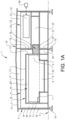
- Fig. 1A shows a bathhouse 1 which comprises an internal building 2 and an external building 3.
- the internal building 2 encloses and shields a wet environment.
- a pool 4 is arranged inside the internal building 2.
- the pool 4 can be for example a swimming pool made in stainless steel which is filled with water for bath. In this case, the pool 4 is arranged above ground level 5 but it could also be lowered to or below the ground level 5.
- the foundations 6 of the internal building for the pool 4 and joists 7 for the floor of the bath section can suitably be made of concrete.
- the internal building 2 and the external building 3 may have a concrete base plate 8 in common, onto which the internal building 2 is placed.
- the internal building 2 has suitably a load-carrying structure which is independent of the external building 3.
- the walls and roof of the internal building are made by wood.
- the internal building 2 has a frame 9 of glued laminated wood.
- the glued laminated wood frame 9 comprises beams 10 and pillars 11 for supporting walls 12 and roof 13 of the internal building 2.
- the walls 12 and roof 13 of the internal building which are arranged to enclose and shield the wet environment, can be produced by one or more wood elements.
- the walls 12 and the roof 13 can be made of cross-laminated wood plates.
- the walls 12 and the roof 13 of the internal building form an inner climate shield which encloses the bath which has a wet environment.
- the internal building 2 is suitably freestanding relative to the external building 3, i.e., the walls and the roof of the internal building 2 and the walls and the roof of the external building 3 are not reciprocally incorporated or interconnected with each other, and walls and roof are not common to the buildings.
- the external building 3 of the bathhouse encloses the internal building 2.
- the internal building 2 is built inside the external building 3.
- the walls 14 and the roof 15 of the external building enclose the internal building 2.
- the walls 14 and the roof 15 of the external building thus form an outer climate barrier against the surrounding outdoor environment.
- the external building 3 may have a glued laminated wood frame 16 comprising beams 17 and pillars 18.
- the walls 14 and the roof 15 of the external building can be made of one or more wood elements in the same way as described for the internal building. Different types of frame, and wall and roof elements, can however be used to the external building 3.
- the walls and the roof of the external building are preferably insulated for reducing heat losses to the surrounding.
- the external building 3 has a frame of steel beams such as a truss for the roof and steel pillars.
- the roof can be provided with a waterproof sheet, a vapour barrier, insulation and a load-bearing plate.
- the walls may comprise sandwich elements, plates och insulation.
- the external building 3 has suitably foundations 19 for the pillars 18 and further the external building 3 and the internal building 2 may have the base plate 8 in common as described hereinabove. In other words; when the external building 3 is built, the internal building 2 can be built on the base plate 8 inside the external building 3. Of course, any preparatory land work, piling and installation of further foundations for the internal building and/or the external building can be performed in accordance with adopted construction technology if required.
- the walls 12 of the internal building and the walls 14 of the external building are arranged at distance from each other such that a space 20 is formed between the internal building 2 and the external building 3.
- the space 20 is formed between the roof 13 of the internal building and the roof 15 of the external building since the roofs are arranged at distance from each other.
- the inner climate shield and the outer climate shield are separated from each other.
- the space between the internal building and the external building will hereinafter also be called buffer zone.
- the bathhouse 1 has a further building 22 which adjoins to the external building 3. More precisely, the external building 3 and the further building 22 are built as one house 23 with a continuous roof structure 21 in common. In this case, the external building 3 and the adjoining further building 22 have a wall 14' in common which at the same time constitutes an interior wall of the house 23 with common continuous roof structure 21.
- the bathhouse 1 has a passage 24 for entry to the internal building 2.
- the passage 24 connects a position 25 outside the external building 3 with a position 26 inside the internal building 2.
- users can get into the bath and out from the bath.
- the passage 24 extending from the external building 3 to the internal building 2 is shielded against the space 20 formed between the internal building 2 and the external building 3.
- the passage 24 has suitably covering floor, walls and ceiling.
- the space 20 has an environment and the passage has another environment which are separated from each other.
- the space 20 formed between the internal building 2 and the external building 3 is suitably shielded against all rooms of the bathhouse intended for users of the bathhouse.
- the passage 24 can be provided with a lock 27 to counteract air flow in the direction from inside the internal building 2 to outside the internal building when passing into and out from the internal building 2. In this way, air from the bath containing chlorine compounds can be prevented from reaching rooms in the further building 22.
- doors can be installed in the passage 24 which shield the space of the lock.
- the lock 27 may be a part of or the entire passage 24.
- a first door 28 may be arranged to open and close to the position 25 outside the external building 3, i.e., here to the further building 22, and a second door 29 may be arranged to open and close to the position 26 inside the internal building 2.
- a lock function can be achieved.
- the lock function can be further improved by a ventilation system of the bathhouse 1 arranged to ventilate the passage 24 and particularly the part which forms the lock 27.
- the ventilation system can be arranged to create an overpressure in the lock 27 relative to the air pressure inside the internal building 2. In this way, transportation of air from the bath to the passage 24 when the second door 29 is open to the bath is counteracted.
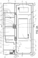
- FIG. 2A shows a plan view of the bathhouse in Fig. 1A . See cut along A-A in Fig. 2A .
- the bathhouse 1 comprises as previously described the internal building 2 and the external building 3.
- the pool 4 there are also a department 30 for family baths and a multipool 31 arranged inside the internal building 2.
- the adjoining further building 22 may comprise a number of changing rooms, such as "LADIES” 31, "MEN” 32 and special changing room 33, with a said passage 24 arranged for each of the changing rooms for entry/exit into and out from the bath in the internal building 2.
- Each passage 24 may be provided with one said lock 27 for counteracting air flow out from the bath to the changing rooms as described hereinabove with reference to Fig. 1A .
- the bathhouse entrance hall 36 may have an entrance 39 into the changing rooms 31, 32, 33 from which rooms the bath can be reached via respective passage 24.
- Both a wall portion 14" of the wall 14 of the external building which shields the bathhouse entrance hall 36 and a wall portion 12" of the wall 12 of the internal building at a corresponding position, can be provided with windows.
- the climate lock 40 may have a first sliding door arranged in the wall portion 14" and a second sliding door arranged in the wall portion 12". Between the first sliding door and the second sliding door a channel 41 is arranged which connects the further building 22 and the internal building 2. In the same way as described for passage 24 for entry to the bath, this channel 41 is suitably shielded from the space 20 and ventilated for counteracting air to flow out from the internal building and into the café 37. Further, an overpressure in the climate lock 40 relative to the pressure in the internal building 2 can be created when the sliding door to the internal building 2 is open.
- the further building 22 may include other rooms 42, such as for example fan rooms, rooms having emergency exits, and rooms with gates 43 to the surroundings for introduction and lifting of materials and building elements during the construction of the bathhouse.
- the distance between the walls of the internal building and the walls of the external building is indicated by a nominal measure denoted X, where X ⁇ 2 meters.
- the distance X creating the space or buffer zone extends from the outside of the wall of the internal building to the inside of the wall of the external building.
- the distance X' is however smaller, such as X' ⁇ 1 meter.
- the buffer zone 20 can be narrower locally. Between the wall portion 12" of the internal building 2 and the wall portion 14" of the external building 3, locally at the windows the distance can be even smaller, for example X" ⁇ 0.5 meters.
- the invention also relates to a method of building a bathhouse 1 with the internal building 2 which encloses and shields the wet environment and the external building 3 which encloses the internal building.
- the method comprises to provide the external building 3, which can be performed by using an already existing building or by new production of the external building 3. Further, to build the internal building 2 inside the existing external building 3 such that the walls 12 of the internal building and the walls 14 of the external building are arranged at a distance from each other and a space 20 is formed between the internal building 2 and the external building 3.
- the internal building can be built such that the distance between the walls 12 of the internal building and the walls 14 of the external building is in the range 0.3-30 meters, suitably in the range 1-30 meters, and preferably in the range 1.5-30 meters.
- Fig. 1B shows a further example embodiment of the bathhouse 1.
- the bathhouse 1 can be connected to a further building 22' arranged adjacent to the external building 3 but at a certain distance from the external building 3.
- the passage 24 extends from the further building 22' to the external building 3, into the external building 3, through the buffer zone 20 and further into inside the internal building 2.
- the further building 22' may have for example a multi-arena with changing rooms and/or a hotel section, and it is possible to move, via the passage 24, between these rooms and the bath in the internal building 2 which has a pool 4.
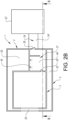
- Fig. 2 B shows a plan view of the bathhouse 1 in Fig. 1B .
- the lock 27 has been combined with showers.
- the lock 27, which constitutes part of the passage 24, comprises a room provided with one or more shower units 45.
- the passage 24 is shielded against the buffer zone 20, i.e., here the combined lock and shower room 46 is shielded against the space 20 formed between the internal building 2 and the external building 3.
- the first door 28 can be arranged to open and close to the passage part 24' of the passage 24 which connects the external building 3 and the further building 22', i.e., to open and close to the further building 22', and the second door 29 can be arranged to open and close to the bath inside the internal building 2.
- Fig. 4 shows a variant of the wall 12 where also a sound-absorbing sheet 56 is arranged on the inside of the wall 12 with an air gap 57 between the wood element 50 and the sound-absorbing sheet 56.
- the thickness of the insulation layer 54' has been increased to maintain a temperature above the condensation point throughout the wall 12. This means that the temperature in the wood element 50 inside the vapour barrier 53, should be higher than the condensation point for the air in the bath in the internal building 2.
- the temperature in the insulation layer 54' is however not critical since the relative humidity in the buffer zone 20 is low. This results in even lower relative humidity in the insulation layer 54' which contains the same amount of moisture as in the buffer zone, but higher temperature than the air in the buffer zone 20.
- the temperature in the space 20 formed between the internal building 2 and the external building 3 can suitably be controlled to be able to maintain the desired temperature.
- the temperature can be controlled to be equal to or higher than a predetermined minimum temperature. This can be achieved by a ventilation system and/or a heating source such as radiators or similar.
- the space 20 also works as buffer zone between the internal building 2 and the external building 3 in case of a leakage from the internal building 2.
- the bathhouse 1 has suitably a ventilation system arranged to ventilate the buffer zone 20 which gives the opportunity to ventilate air such that the external building and ducting installations or other equipment in the buffer zone are not exposed to the corrosive air of the bath in case of a leakage from the internal building 2.
- the temperature and/or the air quality in the buffer zone 20 can be controlled by conventional ventilation equipment for houses.
- the invention also relates to a method of operating of a bathhouse built as described hereinabove.
- the method comprises to maintain a temperature which is equal to or higher than a predetermined minimum temperature in the space 20 formed between the internal building 2 and the external building 3.
- the minimum temperature in the buffer zone 20 can be adapted to the temperature in the internal building 2 and the outdoor temperature.
- the temperature in the internal building 2 is often in the range +28-33°C.
- the temperature in the space 20 formed between the internal building 2 and the external building 3 can be controlled towards a target value in the range +10-30°C, suitably in the range +15-30°C and preferably in the range +18-30°C.
- the temperature in the buffer zone is advantageously controlled to a usual indoor temperature in the range +18-25°C.
- the bathhouse 1 has a control equipment which by means of a ventilation system controls the temperature in the space 20.
- the control equipment 60 and the ventilation system 61 arranged for ventilating the buffer zone 20 are schematically illustrated in Fig. 1A .
- the ventilation system 61 which comprises a ventilation unit, channel system, etc., can be provided with ventilation components well known to the person skilled in the art.
- the ventilation system 61 of the bathhouse 1 is suitably arranged to ventilate the passage 24 and particularly the part which forms the lock 27.
- the ventilation system 61 may comprise a further ventilation unit with associated channel system.
- the ventilation system 61 has a further ventilation unit with associated channel system for ventilating the internal building 2.
- the ventilation system 61 which is schematically illustrated can of course be divided and the different ventilation units can be placed on the substantially same position or on different positions with the respective ducting channels for air to and from the various spaces.
- the major part of these ventilation channels is advantageously arranged in the buffer zone 20 where the climate is not corrosive. This makes it possible to choose simpler materials and simplifies maintenance resulting in reduced costs.
Landscapes
- Health & Medical Sciences (AREA)
- Architecture (AREA)
- Engineering & Computer Science (AREA)
- Public Health (AREA)
- Physical Education & Sports Medicine (AREA)
- Epidemiology (AREA)
- Pain & Pain Management (AREA)
- Rehabilitation Therapy (AREA)
- Life Sciences & Earth Sciences (AREA)
- Animal Behavior & Ethology (AREA)
- General Health & Medical Sciences (AREA)
- Veterinary Medicine (AREA)
- Structural Engineering (AREA)
- Civil Engineering (AREA)
- Residential Or Office Buildings (AREA)
- Buildings Adapted To Withstand Abnormal External Influences (AREA)
Abstract
Description
- The invention relates to a bathhouse and a method of building a bathhouse.
- In the design and construction of bathhouses there are building physical requirements which are significantly different from other house building. One challenge is to apply technology solutions which in a safe way can be implemented in the construction process and competence offered by the market. The conditions which create a lot of challenges are primarily that a bathhouse climate often has a temperature of +30°C and a relative humidity of 55%. The condensation point of bathhouse air is about +22°C. In addition, the outdoor temperature may vary a lot and be as low as down to -30°C. This means that a very large temperature gradient across the walls of the bathhouse in the size of 60°C may be present.
- This in turn places high demands on the building to eliminate the risk of condensation, such as a highly insulated structure, minimization of cold bridges and a tight vapour barrier. Should there be deficiencies in this, condensation of water vapor may take place and condensate is formed within walls and roof causing subsequent problems of moisture and mold and weakening of the structure. Thus, a specific structure, which must be free from defects during the entire life of the building is required.
- Furthermore, the environment in a bathhouse is very aggressive due to supply of chlorine into the bath water of the pools. Chlorine is added to keep the bath water clean from bacteria and contaminants. Chlorine compounds in combination with the moist air create a very corrosive climate which mainly attacks metals. To avoid problem associated with corrosion, as far as possible, high demands are placed on choice of material and the design of both the house structure and the installations of peripherals and furnishings of the bathhouse. For example, electronics, illuminators, channelization for ventilation, electricity and heating installations, etc., are subjected to corrosive attacks. The choice of material and the design of the house structure are largely determined by the bath climate.
- To limit the risks and secure bearing capacity of the structure, concrete structures are traditionally used to a large extent. These constructions are however associated with long construction times, high costs and large carbon dioxide emissions.
- An objective with the invention is to provide a bathhouse which can be built in a rational and cost effective way with reduced climate impact.
- This objective is achieved by a bathhouse comprising an internal building which encloses and shields a wet environment and an external building which encloses the internal building, wherein the walls of the internal building and the walls of the external building are arranged at a distance from each other such that a space is formed between the internal building and the external building.
- The invention is based on the insight that such a bathhouse has great advantages since the climatic barrier which shields the bath can be separated from the climate barrier which shields against the outdoor climate. The space formed between the internal building and the external building may have standard indoor climate. This means that the temperature gradient across the climate barrier which shields the bath can be considerably reduced in comparison with outer walls and roof of a traditional bathhouse.
- Further, such a bathhouse has great advantages since the climate barrier which shields the bath can be separated from the climate barrier which shields adjacent dry rooms. Hereby, the risk of leakage of air and vapor into adjacent dry rooms, and problem with moisture and corrosion resulting therefrom, can be eliminated or at least substantially reduced. The space formed between the internal building and the external building can be ventilated for removing any leakage from the internal building. In this way, traditional building technology and materials can be used for an adjacent building providing the dry rooms outside the external building.
- By a smaller temperature gradient across the walls and roof of the external building as compared to a traditional bathhouse, the energy losses of the bathhouse can be reduced.
- The possibility to perform installations in the space formed between the internal building and the external building is very beneficial since these can be made in an indoor environment shielded from the aggressive environment of the bath as well as the outdoor environment.
- Further, an increased freedom to use less complicated building technology and lighter building materials of walls and roof forming the internal building, which encloses the wet environment, is achieved. For example, wooden structures (which replace concrete structures) can be used which will shorten construction times and reduce costs as well as carbon footprint and other environmental impact. The risk of condensation in walls and roof is also reduced at the same time as arranging of wall penetrations and installations of the peripherals are facilitated.
- In the same way as for the walls, the roof of the internal building and the roof of the external building are suitably arranged at a distance from each other such that the space formed between the internal building and the external building extends around and over the internal building.
- The invention also opens for reuse and exploitation of already existing buildings. The internal building may be built inside an already existing building which then constitutes the external building of the bathhouse. For example, buildings which have been used as machine halls can be used for building the bathhouse. Both in the case when an existing building is used and when the external building is a new building, the construction work with the internal building can be performed indoors, i.e., inside the external building. The use of the external building as weather protection facilitates the implementation and shortens construction time for the internal building.
- It should be stressed that the term bathhouse is intended to include not only traditional bathhouses with swimming pools, but also swimming halls with pools, spa facilities, adventure pools with rides such as slides and similar, which all in some way provide bath indoors in swimming pools or other pool.
- According to one embodiment of the bathhouse, the internal building has a load-carrying structure which is independent of the external building. Hereby, the internal building can be built independently and the external building does not need to be dimensioned to carry any load from the internal building.
- According to a further embodiment of the bathhouse, the internal building is freestanding relative to the external building. Hereby, the internal building and the external building do not need to be adapted to be reciprocally incorporated, though some adaptation of the external building may be required to provide access to the internal building and to facilitate the construction of the internal building.
- According to a further embodiment of the bathhouse, the temperature in the space formed between the internal building and the external building is controlled to be equal to or higher than a predetermined minimum temperature, and preferably the bathhouse has a ventilation system arranged to ventilate the space formed between the internal building and the external building. Hereby, the space can constitute a buffer zone which can have indoor climate, or at least indoor temperature, and any leakage from the internal building to the space can be taken care of effectively.
- According to a further embodiment, the bathhouse has a control equipment which controls the temperature in the space formed between the internal building and the external building towards a target value in the range +10-30°C, suitably in the range +15-30°C and preferably in the range +18-30°C. Even if it is entirely possible to control the temperature towards a target value in the range +10-18°C, it is often suitable that the temperature in the space is controlled towards a target value in the range +18-25°C. In this way, the temperature in the space formed between the internal building and the external building can be adapted to the bathhouse climate in the internal building. A relatively small temperature gradient across the walls of the internal building can be achieved such that condensation is counteracted.
- According to a further embodiment of the bathhouse, the distance between the walls of the internal building and the walls of the external building, is in the range 0.3-30 meters, suitably in the range 1-30 meters and preferably in the range 1.5-30 meters.
- In pure new constructions, the distance can be 0.3-5 meters, preferably 1-3 meters, whereas when using an already existing building constituting the external building, the distance can be significantly larger. A distance of 2 meters will give a good buffer zone at the same time as there is sufficient space for facilitating construction of the internal building and for arranging channelization and equipment for operating the bathhouse in this space.
- The distance between the walls may however vary for different positions and the measure mentioned above is to be regarded as a nominal measure which is present for the major part of or substantially the entire space, but deviations may occur, for example where windows are situated, where the distance can be somewhat smaller than the nominal measure and/or at other single positions, where the distance can be larger than the nominal measure.
- In a similar way, the distance between the roof of the internal building and the roof of the external building may be in the size of 0.3-5 meters, preferably 1-3 meters. The distance can of course be larger, for example in the case an already existing building is used as the external building, and the existing building has a ceiling height that substantially exceeds the requisite height of the internal building.
- According to a further embodiment, the bathhouse has a passage for entry to the internal building, wherein the passage connects a position outside the external building with a position inside the internal building, and the passage is shielded against the space formed between the internal building and the external building. Hereby, users of the bathhouse can easily get into the bath via the passage, at the same time as they cannot reach the space formed between the internal building and the external building which space is not intended for other than operation and maintenance personnel. Preferably, the space formed between the internal building and the external building is shielded against all rooms of the bathhouse intended for users of the bathhouse.
- According to a further embodiment, the bathhouse has a further building which adjoins the external building, or the bathhouse is connected to a further building arranged adjacent to the external building, and the passage connects the further building and the internal building to each other. Hereby, changing rooms, shower rooms and/or halls for sport can be situated adjacent to the bath. The users of the bathhouse can use the changing rooms and showers in the further building and then reach the internal building by walking via the passage from a position indoors in the further building into the bath.
- According to a further embodiment of the bathhouse, the external building and the further building are built as one house with a continuous roof structure in common. Hereby, one and the same house can be used for both the external building of the bathhouse and other facilities directly adjacent to the bath. One or more interior walls of the house can constitute walls of the external building of the bathhouse.
- According to a further embodiment of the bathhouse, the passage has a lock to counteract air flow in the direction from inside the internal building to outside the internal building when passing into and out from the internal building, and preferably the bathhouse has a ventilation system arranged to ventilate the passage. Hereby, dispersion of chlorine compounds from the bath to the surroundings can be counteracted in a rational way. For example, the ventilation system can be arranged to create an overpressure in the lock relative to the air pressure inside the internal building.
- According to a further embodiment of the bathhouse, the lock comprises a room provided with one or more shower units. Hereby, showers can be arranged such that users of the bathhouse in a natural way or compelling way will take a shower immediately before entering into the bath which is important for hygienic reasons. The showers can of course be used also after completed bath.
- According to a further embodiment of the bathhouse, the walls and/or roof of the internal building are made of wood, and preferably the walls and/or roof of the internal building are made of cross-laminated wood plates. Hereby, a time efficient and cost effective construction method is achieved where a major part of the internal building can be prefabricated.
- According to a further embodiment of the bathhouse, the walls and/or roof of the internal building comprises one or more wood elements with a first inner surface faced towards the enclosed wet environment and a second outer surface faced towards the external building, and a vapour barrier which is arranged outside the second outer surface of the wood element, and an insulation layer which is arranged outside the vapour barrier. Hereby, a wall safe against condensation can be achieved which in addition is relatively insensitive to single minor leakage through the wall. The vapour barrier can be for example an airtight plastic film or membrane with an adapted resistance to water vapour migration. Further, by the use of wood elements, it is possible to arrange wall penetrations from installations in the space outside the internal building into the environment inside the internal building in a relatively easy way, both during the construction production and after the bathhouse has been put into operation.
- The invention also relates to a method of building a bathhouse and a method of operating a bathhouse. The advantages associated with these methods are substantially the same as described hereinabove for the different embodiments of the bathhouse.
- Further advantages and advantageous features of the invention are disclosed in the following description and the claims.
- With reference to the appended drawings, below follows a more detailed description of embodiments of the invention cited as examples.
- In the drawings:
-
Fig. 1A is a cut side view of a bathhouse, -
Fig. 1B is a cut side view illustrating a variant of the bathhouse, -
Fig. 2A is a plan view showing the bathhouse inFig. 1A , -
Fig. 2B is a plan view showing the bathhouse inFig. 1B , -
Fig. 3 is a cross section view showing a part of a wall, and -
Fig. 4 is a cross section view showing a variant of a wall. -
Fig. 1A shows a bathhouse 1 which comprises aninternal building 2 and anexternal building 3. Theinternal building 2 encloses and shields a wet environment. Apool 4 is arranged inside theinternal building 2. Thepool 4 can be for example a swimming pool made in stainless steel which is filled with water for bath. In this case, thepool 4 is arranged above ground level 5 but it could also be lowered to or below the ground level 5. Thefoundations 6 of the internal building for thepool 4 andjoists 7 for the floor of the bath section, can suitably be made of concrete. Theinternal building 2 and theexternal building 3 may have aconcrete base plate 8 in common, onto which theinternal building 2 is placed. - The
internal building 2 has suitably a load-carrying structure which is independent of theexternal building 3. Although many materials and designs could be used for theinternal building 2, in this example embodiment the walls and roof of the internal building are made by wood. For this purpose, theinternal building 2 has a frame 9 of glued laminated wood. The glued laminated wood frame 9 comprises beams 10 andpillars 11 for supportingwalls 12 androof 13 of theinternal building 2. Thewalls 12 androof 13 of the internal building which are arranged to enclose and shield the wet environment, can be produced by one or more wood elements. For example, thewalls 12 and theroof 13 can be made of cross-laminated wood plates. In other words; thewalls 12 and theroof 13 of the internal building form an inner climate shield which encloses the bath which has a wet environment. Theinternal building 2 is suitably freestanding relative to theexternal building 3, i.e., the walls and the roof of theinternal building 2 and the walls and the roof of theexternal building 3 are not reciprocally incorporated or interconnected with each other, and walls and roof are not common to the buildings. - The
external building 3 of the bathhouse encloses theinternal building 2. Theinternal building 2 is built inside theexternal building 3. Thewalls 14 and the roof 15 of the external building enclose theinternal building 2. Thewalls 14 and the roof 15 of the external building thus form an outer climate barrier against the surrounding outdoor environment. Theexternal building 3 may have a glued laminated wood frame 16 comprisingbeams 17 andpillars 18. Thewalls 14 and the roof 15 of the external building can be made of one or more wood elements in the same way as described for the internal building. Different types of frame, and wall and roof elements, can however be used to theexternal building 3. The walls and the roof of the external building are preferably insulated for reducing heat losses to the surrounding. According to an alternative embodiment, theexternal building 3 has a frame of steel beams such as a truss for the roof and steel pillars. The roof can be provided with a waterproof sheet, a vapour barrier, insulation and a load-bearing plate. The walls may comprise sandwich elements, plates och insulation. - The
external building 3 has suitablyfoundations 19 for thepillars 18 and further theexternal building 3 and theinternal building 2 may have thebase plate 8 in common as described hereinabove. In other words; when theexternal building 3 is built, theinternal building 2 can be built on thebase plate 8 inside theexternal building 3. Of course, any preparatory land work, piling and installation of further foundations for the internal building and/or the external building can be performed in accordance with adopted construction technology if required. - The
walls 12 of the internal building and thewalls 14 of the external building are arranged at distance from each other such that aspace 20 is formed between theinternal building 2 and theexternal building 3. In a corresponding way, thespace 20 is formed between theroof 13 of the internal building and the roof 15 of the external building since the roofs are arranged at distance from each other. Hereby, the inner climate shield and the outer climate shield are separated from each other. The space between the internal building and the external building will hereinafter also be called buffer zone. - In the example embodiment illustrated in
Fig. 1A , the bathhouse 1 has afurther building 22 which adjoins to theexternal building 3. More precisely, theexternal building 3 and thefurther building 22 are built as onehouse 23 with acontinuous roof structure 21 in common. In this case, theexternal building 3 and the adjoining further building 22 have a wall 14' in common which at the same time constitutes an interior wall of thehouse 23 with commoncontinuous roof structure 21. - Further, the bathhouse 1 has a
passage 24 for entry to theinternal building 2. Thepassage 24 connects aposition 25 outside theexternal building 3 with aposition 26 inside theinternal building 2. By means of thepassage 24 users can get into the bath and out from the bath. Thepassage 24 extending from theexternal building 3 to theinternal building 2 is shielded against thespace 20 formed between theinternal building 2 and theexternal building 3. For this purpose, thepassage 24 has suitably covering floor, walls and ceiling. In other words, thespace 20 has an environment and the passage has another environment which are separated from each other. Further, thespace 20 formed between theinternal building 2 and theexternal building 3 is suitably shielded against all rooms of the bathhouse intended for users of the bathhouse. - In this example embodiment illustrated in
Fig. 1A , thepassage 24 connects thefurther building 22 and theinternal building 2 to each other. This means that users of the bathhouse may move from a place indoors of thefurther building 22 to place indoors of theinternal building 2 to reach the bath without passing outdoors. They can move from changing rooms, showers, etc., directly to the bath in theinternal building 2, and certainly also move via thepassage 24 in the opposite direction from the bath to changing rooms, showers, etc., after completing the bath. - As also is shown in the corresponding view in
Fig. 2A , thepassage 24 can be provided with alock 27 to counteract air flow in the direction from inside theinternal building 2 to outside the internal building when passing into and out from theinternal building 2. In this way, air from the bath containing chlorine compounds can be prevented from reaching rooms in thefurther building 22. For example, doors can be installed in thepassage 24 which shield the space of the lock. Thelock 27 may be a part of or theentire passage 24. Afirst door 28 may be arranged to open and close to theposition 25 outside theexternal building 3, i.e., here to thefurther building 22, and asecond door 29 may be arranged to open and close to theposition 26 inside theinternal building 2. By making sure that thefirst door 28 and thesecond door 29 have door closers and cannot be set open, a lock function can be achieved. The lock function can be further improved by a ventilation system of the bathhouse 1 arranged to ventilate thepassage 24 and particularly the part which forms thelock 27. The ventilation system can be arranged to create an overpressure in thelock 27 relative to the air pressure inside theinternal building 2. In this way, transportation of air from the bath to thepassage 24 when thesecond door 29 is open to the bath is counteracted. - As mentioned above,
Fig. 2A shows a plan view of the bathhouse inFig. 1A . See cut along A-A inFig. 2A . The bathhouse 1 comprises as previously described theinternal building 2 and theexternal building 3. In addition to thepool 4, there are also adepartment 30 for family baths and a multipool 31 arranged inside theinternal building 2. - The adjoining further building 22 may comprise a number of changing rooms, such as "LADIES" 31, "MEN" 32 and
special changing room 33, with a saidpassage 24 arranged for each of the changing rooms for entry/exit into and out from the bath in theinternal building 2. Eachpassage 24 may be provided with one saidlock 27 for counteracting air flow out from the bath to the changing rooms as described hereinabove with reference toFig. 1A . Further, as illustrated it is possible to arrange anentrance 34 to thefurther building 22, elevator andstairwell 35, and abathhouse entrance hall 36 with acafé 37, kitchen andstorage 38, etc. Thebathhouse entrance hall 36 may have anentrance 39 into the changingrooms respective passage 24. - Both a
wall portion 14" of thewall 14 of the external building which shields thebathhouse entrance hall 36 and awall portion 12" of thewall 12 of the internal building at a corresponding position, can be provided with windows. - It is also possible to arrange a
smaller climate lock 40, to enable goods the bathers would like to buy to be brought from thecafé 37 into the bath inside theinternal building 2, and to arrange for the associated payment of the goods. Theclimate lock 40 may have a first sliding door arranged in thewall portion 14" and a second sliding door arranged in thewall portion 12". Between the first sliding door and the second sliding door achannel 41 is arranged which connects thefurther building 22 and theinternal building 2. In the same way as described forpassage 24 for entry to the bath, thischannel 41 is suitably shielded from thespace 20 and ventilated for counteracting air to flow out from the internal building and into thecafé 37. Further, an overpressure in theclimate lock 40 relative to the pressure in theinternal building 2 can be created when the sliding door to theinternal building 2 is open. - In addition, the
further building 22 may includeother rooms 42, such as for example fan rooms, rooms having emergency exits, and rooms withgates 43 to the surroundings for introduction and lifting of materials and building elements during the construction of the bathhouse. - Further, in the example embodiment illustrated in
Fig. 2A , the distance between the walls of the internal building and the walls of the external building is indicated by a nominal measure denoted X, where X≈2 meters. The distance X creating the space or buffer zone extends from the outside of the wall of the internal building to the inside of the wall of the external building. At some positions where windows are arranged on the internal building and on the external building the distance X' is however smaller, such as X'≈1 meter. In these areas with windows, thebuffer zone 20 can be narrower locally. Between thewall portion 12" of theinternal building 2 and thewall portion 14" of theexternal building 3, locally at the windows the distance can be even smaller, for example X"≈0.5 meters. - The invention also relates to a method of building a bathhouse 1 with the
internal building 2 which encloses and shields the wet environment and theexternal building 3 which encloses the internal building. The method comprises to provide theexternal building 3, which can be performed by using an already existing building or by new production of theexternal building 3. Further, to build theinternal building 2 inside the existingexternal building 3 such that thewalls 12 of the internal building and thewalls 14 of the external building are arranged at a distance from each other and aspace 20 is formed between theinternal building 2 and theexternal building 3. The internal building can be built such that the distance between thewalls 12 of the internal building and thewalls 14 of the external building is in the range 0.3-30 meters, suitably in the range 1-30 meters, and preferably in the range 1.5-30 meters. -
Fig. 1B shows a further example embodiment of the bathhouse 1. Same reference numerals as inFig. 1A have been used for corresponding components and positions. As shown inFig. 1B , the bathhouse 1 can be connected to a further building 22' arranged adjacent to theexternal building 3 but at a certain distance from theexternal building 3. Thepassage 24 extends from the further building 22' to theexternal building 3, into theexternal building 3, through thebuffer zone 20 and further into inside theinternal building 2. The further building 22' may have for example a multi-arena with changing rooms and/or a hotel section, and it is possible to move, via thepassage 24, between these rooms and the bath in theinternal building 2 which has apool 4. -
Fig. 2 B shows a plan view of the bathhouse 1 inFig. 1B . In this example embodiment thelock 27 has been combined with showers. Thelock 27, which constitutes part of thepassage 24, comprises a room provided with one ormore shower units 45. In the same way as previously described, thepassage 24 is shielded against thebuffer zone 20, i.e., here the combined lock andshower room 46 is shielded against thespace 20 formed between theinternal building 2 and theexternal building 3. Thefirst door 28 can be arranged to open and close to the passage part 24' of thepassage 24 which connects theexternal building 3 and the further building 22', i.e., to open and close to the further building 22', and thesecond door 29 can be arranged to open and close to the bath inside theinternal building 2. -
Figure 3 shows a cross section view of an example embodiment of awall 12 of theinternal building 2. Thewall 12 has awood element 50 with a firstinner surface 51 faced towards the enclosed wet environment and a second outer surface 52 faced towards theexternal building 3, and avapour barrier 53 which is arranged outside the second outer surface 52 of the wood element, and aninsulation layer 54 which is arranged outside thevapour barrier 53, and in some cases an outer layer 55 which is boundary to the buffer zone. The outer layer 55 can be a surface layer for providing a surface with increased cleanability or a sheet material for improving the ability to walk on the roof of the internal building where access is required to perform installations. -
Fig. 4 shows a variant of thewall 12 where also a sound-absorbingsheet 56 is arranged on the inside of thewall 12 with anair gap 57 between thewood element 50 and the sound-absorbingsheet 56. To compensate for the temperature drop across thissheet 56, the thickness of the insulation layer 54' has been increased to maintain a temperature above the condensation point throughout thewall 12. This means that the temperature in thewood element 50 inside thevapour barrier 53, should be higher than the condensation point for the air in the bath in theinternal building 2. The temperature in the insulation layer 54' is however not critical since the relative humidity in thebuffer zone 20 is low. This results in even lower relative humidity in the insulation layer 54' which contains the same amount of moisture as in the buffer zone, but higher temperature than the air in thebuffer zone 20. - For all embodiments of the bathhouse, the temperature in the
space 20 formed between theinternal building 2 and theexternal building 3 can suitably be controlled to be able to maintain the desired temperature. The temperature can be controlled to be equal to or higher than a predetermined minimum temperature. This can be achieved by a ventilation system and/or a heating source such as radiators or similar. - The
space 20 also works as buffer zone between theinternal building 2 and theexternal building 3 in case of a leakage from theinternal building 2. The bathhouse 1 has suitably a ventilation system arranged to ventilate thebuffer zone 20 which gives the opportunity to ventilate air such that the external building and ducting installations or other equipment in the buffer zone are not exposed to the corrosive air of the bath in case of a leakage from theinternal building 2. - Thus, the temperature and/or the air quality in the
buffer zone 20 can be controlled by conventional ventilation equipment for houses. - The invention also relates to a method of operating of a bathhouse built as described hereinabove. The method comprises to maintain a temperature which is equal to or higher than a predetermined minimum temperature in the
space 20 formed between theinternal building 2 and theexternal building 3. The minimum temperature in thebuffer zone 20 can be adapted to the temperature in theinternal building 2 and the outdoor temperature. The temperature in theinternal building 2 is often in the range +28-33°C. The temperature in thespace 20 formed between theinternal building 2 and theexternal building 3 can be controlled towards a target value in the range +10-30°C, suitably in the range +15-30°C and preferably in the range +18-30°C. The temperature in the buffer zone is advantageously controlled to a usual indoor temperature in the range +18-25°C. - For this purpose, the bathhouse 1 has a control equipment which by means of a ventilation system controls the temperature in the
space 20. Thecontrol equipment 60 and theventilation system 61 arranged for ventilating thebuffer zone 20 are schematically illustrated inFig. 1A . Theventilation system 61 which comprises a ventilation unit, channel system, etc., can be provided with ventilation components well known to the person skilled in the art. - As previously described, the
ventilation system 61 of the bathhouse 1 is suitably arranged to ventilate thepassage 24 and particularly the part which forms thelock 27. For achieving this, theventilation system 61 may comprise a further ventilation unit with associated channel system. In the same way, theventilation system 61 has a further ventilation unit with associated channel system for ventilating theinternal building 2. Theventilation system 61 which is schematically illustrated can of course be divided and the different ventilation units can be placed on the substantially same position or on different positions with the respective ducting channels for air to and from the various spaces. The major part of these ventilation channels is advantageously arranged in thebuffer zone 20 where the climate is not corrosive. This makes it possible to choose simpler materials and simplifies maintenance resulting in reduced costs. - It is to be understood that the present invention is not limited to the embodiments described above and illustrated in the drawings; rather, the skilled person will recognize that many changes and modifications may be made within the scope of the appended claims.
Claims (15)
- A bathhouse (1) comprising an internal building (2) which encloses and shields a wet environment and an external building (3) which encloses the internal building, wherein the walls (12) of the internal building and the walls (14) of the external building are arranged at a distance from each other such that a space (20) is formed between the internal building (2) and the external building (3), characterized in that the walls (12) and/or roof (13) of the internal building comprises one or more wood elements (50) with a first inner surface (51) faced towards the enclosed wet environment and a second outer surface (52) faced towards the external building (3), and a vapour barrier (53) which is arranged outside the second outer surface (52) of the wood element, and an insulation layer (54) which is arranged outside the vapour barrier (53).
- A bathhouse according to claim 1, characterized in that the internal building (2) has a load-carrying structure (9) which is independent of the external building (3).
- A bathhouse according to claim 1 or 2, characterized in that the internal building (2) is freestanding relative to the external building (3).
- A bathhouse according to any preceding claim, characterized in that the temperature in the space (20) formed between the internal building (2) and the external building (3) is controlled to be equal to or higher than a predetermined minimum temperature.
- A bathhouse according to claim 4, characterized in that the bathhouse (1) has a ventilation system (61) arranged to ventilate the space (20) formed between the internal building (2) and the external building (3).
- A bathhouse according to any preceding claim, characterized in that the bathhouse (1) has a control equipment (60) which controls the temperature in the space (20) formed between the internal building (2) and the external building (3) towards a target value in the range +10-30°C, suitably in the range +15-30°C and preferably in the range +18-30°C.
- A bathhouse according to any preceding claim, characterized in that the distance (20) between the walls (12) of the internal building and the walls (14) of the external building is in the range 0.3-30 meters, suitably in the range 1-30 meters and preferably in the range 1.5-30 meters.
- A bathhouse according to any preceding claim, characterized in that the bathhouse (1) has a passage (24) for entry to the internal building (2), the passage connecting a position (25) outside the external building (3) with a position (26) inside the internal building (2), and the passage being shielded against the space (20) formed between the internal building (2) and the external building (3).
- A bathhouse according to claim 8, characterized in that the bathhouse (1) has a further building (22) which adjoins the external building (3), or the bathhouse (1) is connected to a further building (22') arranged adjacent to the external building (3), and the passage (24) connects the further building (22; 22') and the internal building (2) to each other.
- A bathhouse according to claim 9, characterized in that the external building (3) and the further building (22) are built as one house (23) with a continuous roof structure (21) in common.
- A bathhouse according to any of claims 8-10, characterized in that the passage (24) has a lock (27) to counteract air flow in the direction from inside the internal building to outside the internal building when passing into and out from the internal building (2).
- A bathhouse according to any of claims 8-11, characterized in that the bathhouse (1) has a ventilation system (61) arranged to ventilate the passage (24).
- A bathhouse according to claim 11 or 12, characterized in that the ventilation system (61) is arranged to create an overpressure in the lock (27) relative to the air pressure inside the internal building (2).
- A bathhouse according to claim 11 or 13, characterized in that the lock (27) comprises a room (46) provided with one or more shower units (45).
- A bathhouse according to any preceding claim, characterized in that the walls (12) and/or roof (13) of the internal building are made of wood, and preferably made of cross-laminated wood plates.
Applications Claiming Priority (3)
| Application Number | Priority Date | Filing Date | Title |
|---|---|---|---|
| SE2150700A SE545206C2 (en) | 2021-06-01 | 2021-06-01 | A BATH HOUSE WITH AN INTERIOR BUILDING THAT ENCLOSES AND PROTECTS A WET ENVIRONMENT AND AN OUTER BUILDING THAT ENCLOSES THE INTERIOR BUILDING |
| EP22703924.5A EP4347974B1 (en) | 2021-06-01 | 2022-02-03 | Bathhouse |
| PCT/EP2022/052626 WO2022253470A1 (en) | 2021-06-01 | 2022-02-03 | A bathhouse and a method of building a bathhouse |
Related Parent Applications (2)
| Application Number | Title | Priority Date | Filing Date |
|---|---|---|---|
| EP22703924.5A Division EP4347974B1 (en) | 2021-06-01 | 2022-02-03 | Bathhouse |
| EP22703924.5A Division-Into EP4347974B1 (en) | 2021-06-01 | 2022-02-03 | Bathhouse |
Publications (2)
| Publication Number | Publication Date |
|---|---|
| EP4545733A2 true EP4545733A2 (en) | 2025-04-30 |
| EP4545733A3 EP4545733A3 (en) | 2025-08-06 |
Family
ID=80446438
Family Applications (2)
| Application Number | Title | Priority Date | Filing Date |
|---|---|---|---|
| EP22703924.5A Active EP4347974B1 (en) | 2021-06-01 | 2022-02-03 | Bathhouse |
| EP25164654.3A Withdrawn EP4545733A3 (en) | 2021-06-01 | 2022-02-03 | Bathhouse |
Family Applications Before (1)
| Application Number | Title | Priority Date | Filing Date |
|---|---|---|---|
| EP22703924.5A Active EP4347974B1 (en) | 2021-06-01 | 2022-02-03 | Bathhouse |
Country Status (3)
| Country | Link |
|---|---|
| EP (2) | EP4347974B1 (en) |
| SE (1) | SE545206C2 (en) |
| WO (1) | WO2022253470A1 (en) |
Family Cites Families (12)
| Publication number | Priority date | Publication date | Assignee | Title |
|---|---|---|---|---|
| DE1684634C3 (en) * | 1967-05-03 | 1974-10-31 | Ibaco Bau-Coordinierungsgesellschaft Mbh & Co Kg, 5620 Velbert | All-weather indoor pool |
| CH467919A (en) * | 1967-11-02 | 1969-01-31 | Jules Egli Ag Bauunternehmung | swimming pool |
| FR2127117A5 (en) * | 1971-02-24 | 1972-10-13 | Walrave Louis | |
| AT331001B (en) * | 1973-11-14 | 1976-07-26 | Groll Hartmut | BUILDINGS FOR SPORTY OR HEALTH PURPOSES |
| AT329815B (en) * | 1974-03-25 | 1976-05-25 | Maderna Alfons | UNDERFLOOR POOL |
| DE2614529C3 (en) * | 1976-04-03 | 1979-10-31 | Roland 6953 Gundelsheim Bender | Insulating cladding for rooms |
| DE2740196A1 (en) * | 1977-09-07 | 1979-03-08 | Fritz Klinke | Prefabricated steel swimming pool unit for cellar - has connecting lugs and flanges for panelled hangar structure and floor |
| DE3230749C2 (en) * | 1982-08-18 | 1986-04-30 | Wolfgang Dipl.-Kaufm. 5100 Aachen Wever | Device for dehumidifying a swimming pool |
| US4718130A (en) * | 1984-08-31 | 1988-01-12 | Interpools Systems, Inc. | Interdome enclosure system for a heated swimming pool |
| DE3808436A1 (en) * | 1988-03-14 | 1989-09-28 | Rolf Eisele | Indoor swimming pool |
| DE102007047486A1 (en) * | 2007-10-04 | 2009-04-09 | Salz, Jürgen F. | building |
| RU175360U1 (en) * | 2017-06-28 | 2017-12-01 | Юрий Степанович Левчук | BATTERY BATHROOM "IN BLACK" |
-
2021
- 2021-06-01 SE SE2150700A patent/SE545206C2/en unknown
-
2022
- 2022-02-03 WO PCT/EP2022/052626 patent/WO2022253470A1/en not_active Ceased
- 2022-02-03 EP EP22703924.5A patent/EP4347974B1/en active Active
- 2022-02-03 EP EP25164654.3A patent/EP4545733A3/en not_active Withdrawn
Also Published As
| Publication number | Publication date |
|---|---|
| WO2022253470A1 (en) | 2022-12-08 |
| EP4347974A1 (en) | 2024-04-10 |
| SE545206C2 (en) | 2023-05-23 |
| SE2150700A1 (en) | 2022-12-02 |
| EP4347974C0 (en) | 2025-05-07 |
| EP4545733A3 (en) | 2025-08-06 |
| EP4347974B1 (en) | 2025-05-07 |
Similar Documents
| Publication | Publication Date | Title |
|---|---|---|
| Knaack et al. | Façades: principles of construction | |
| CA1230461A (en) | Enclosure conditioned housing system | |
| Knaack et al. | Fassaden: Prinzipien der Konstruktion | |
| Ostojić et al. | Energy analysis and refurbishment strategy for Zagreb University buildings: Former Faculty of Technology in Zagreb by Alfred Albini | |
| Lstiburek et al. | Air pressure and building envelopes | |
| EP4347974B1 (en) | Bathhouse | |
| CN107269106B (en) | Noiseless closed fireproof high-rise building without digging ground well and with natural air conditioner two-storey building garage | |
| RU2112850C1 (en) | Dwelling building with added structures | |
| SE2250631A1 (en) | A bath house and a method of constructing a bath house | |
| JP2022155960A (en) | Renovation method and building | |
| JP2007162388A (en) | Building | |
| JP4873932B2 (en) | building | |
| JP4607739B2 (en) | building | |
| JP5133615B2 (en) | building | |
| JP4542497B2 (en) | building | |
| CN208329680U (en) | Accessible household elevator outside a kind of building | |
| NO20180399A1 (en) | Housing system consisting of several floors with ISO containers. | |
| Jasiczak et al. | W sprawie nowoczesnego budownictwa wielkopłytowego. Postulaty rozwiązań technicznych i kierunki rozwoju | |
| JP4695486B2 (en) | building | |
| JP5467755B2 (en) | building | |
| JP4701074B2 (en) | building | |
| DK201870139A1 (en) | RESTORABLE FLOOR HOUSING SYSTEM | |
| Meijs et al. | Components and Connections in Architecture. Principles of Construction | |
| Charles | Steel Structures that Breathe: Two Extensively Glazed Buildings that Integrate Natural Ventilation within Structural Members | |
| Hagerman | Hammer & Hand's construction methods and approach to the glasswood commercial passive house retrofit |
Legal Events
| Date | Code | Title | Description |
|---|---|---|---|
| PUAI | Public reference made under article 153(3) epc to a published international application that has entered the european phase |
Free format text: ORIGINAL CODE: 0009012 |
|
| STAA | Information on the status of an ep patent application or granted ep patent |
Free format text: STATUS: THE APPLICATION HAS BEEN PUBLISHED |
|
| AC | Divisional application: reference to earlier application |
Ref document number: 4347974 Country of ref document: EP Kind code of ref document: P |
|
| AK | Designated contracting states |
Kind code of ref document: A2 Designated state(s): AL AT BE BG CH CY CZ DE DK EE ES FI FR GB GR HR HU IE IS IT LI LT LU LV MC MK MT NL NO PL PT RO RS SE SI SK SM TR |
|
| PUAL | Search report despatched |
Free format text: ORIGINAL CODE: 0009013 |
|
| AK | Designated contracting states |
Kind code of ref document: A3 Designated state(s): AL AT BE BG CH CY CZ DE DK EE ES FI FR GB GR HR HU IE IS IT LI LT LU LV MC MK MT NL NO PL PT RO RS SE SI SK SM TR |
|
| RIC1 | Information provided on ipc code assigned before grant |
Ipc: E04H 3/16 20060101AFI20250702BHEP Ipc: A61H 33/06 20060101ALI20250702BHEP |
|
| STAA | Information on the status of an ep patent application or granted ep patent |
Free format text: STATUS: THE APPLICATION IS DEEMED TO BE WITHDRAWN |
|
| 18D | Application deemed to be withdrawn |
Effective date: 20260207 |