EP4545430A2 - Kassette und vorrichtung zur verwendung bei der entsorgung von abfallstoffen in ein langgestrecktes flexibles rohr - Google Patents
Kassette und vorrichtung zur verwendung bei der entsorgung von abfallstoffen in ein langgestrecktes flexibles rohr Download PDFInfo
- Publication number
- EP4545430A2 EP4545430A2 EP25163809.4A EP25163809A EP4545430A2 EP 4545430 A2 EP4545430 A2 EP 4545430A2 EP 25163809 A EP25163809 A EP 25163809A EP 4545430 A2 EP4545430 A2 EP 4545430A2
- Authority
- EP
- European Patent Office
- Prior art keywords
- cassette
- sides
- projecting
- receptacle
- generally
- Prior art date
- Legal status (The legal status is an assumption and is not a legal conclusion. Google has not performed a legal analysis and makes no representation as to the accuracy of the status listed.)
- Pending
Links
Images


Classifications
-
- B—PERFORMING OPERATIONS; TRANSPORTING
- B65—CONVEYING; PACKING; STORING; HANDLING THIN OR FILAMENTARY MATERIAL
- B65F—GATHERING OR REMOVAL OF DOMESTIC OR LIKE REFUSE
- B65F1/00—Refuse receptacles; Accessories therefor
- B65F1/0006—Flexible refuse receptables, e.g. bags, sacks
-
- B—PERFORMING OPERATIONS; TRANSPORTING
- B65—CONVEYING; PACKING; STORING; HANDLING THIN OR FILAMENTARY MATERIAL
- B65F—GATHERING OR REMOVAL OF DOMESTIC OR LIKE REFUSE
- B65F1/00—Refuse receptacles; Accessories therefor
- B65F1/04—Refuse receptacles; Accessories therefor with removable inserts
- B65F1/06—Refuse receptacles; Accessories therefor with removable inserts with flexible inserts, e.g. bags or sacks
- B65F1/062—Refuse receptacles; Accessories therefor with removable inserts with flexible inserts, e.g. bags or sacks having means for storing or dispensing spare bags
-
- B—PERFORMING OPERATIONS; TRANSPORTING
- B65—CONVEYING; PACKING; STORING; HANDLING THIN OR FILAMENTARY MATERIAL
- B65F—GATHERING OR REMOVAL OF DOMESTIC OR LIKE REFUSE
- B65F2230/00—Shapes of refuse receptacles
- B65F2230/148—Sleeve
-
- B—PERFORMING OPERATIONS; TRANSPORTING
- B65—CONVEYING; PACKING; STORING; HANDLING THIN OR FILAMENTARY MATERIAL
- B65F—GATHERING OR REMOVAL OF DOMESTIC OR LIKE REFUSE
- B65F2240/00—Types of refuse collected
- B65F2240/132—Diapers
-
- B—PERFORMING OPERATIONS; TRANSPORTING
- B65—CONVEYING; PACKING; STORING; HANDLING THIN OR FILAMENTARY MATERIAL
- B65F—GATHERING OR REMOVAL OF DOMESTIC OR LIKE REFUSE
- B65F2240/00—Types of refuse collected
- B65F2240/136—Dog dirt
Definitions
- the invention generally relates to the disposing of waste materials into a waste storage container and in particular relates to a cassette and a waste storage container for use in disposing waste materials.
- the loading of the cassette into the container generally requires the user to insert the cassette into a cassette holding area of the container, to pull from the cassette a portion of flexible tubing, to form a knot in the end of the flexible tubing and to pass the knotted end of the flexible tubing into an enclosure of the container in which waste material is stored.
- the invention provides a cassette for packing waste material into an elongated tube of flexible material, the cassette, comprising a ring-shaped receptacle defining a central opening, the central opening extending along a generally vertical axis, the ring-shaped receptacle defining a storage area receiving a length of elongated tube of flexible material in a folded condition outward of the central opening.
- the cassette further includes a plurality of projecting elements in a spaced apart relationship, the projecting elements extending from a periphery of the cassette and being configured to support the cassette in a waste storage container.
- ring-shape means a closed figure.
- Specific examples include an annular shape, an oval shape, a rectangular or square shape, hexagonal, octagonal, and/or any other polygonal closed figure shape.
- the plurality of projecting elements lie in a common imaginary plane, which is preferably horizontal.
- Each projecting element has an extent in a peripheral direction of the cassette that is significantly larger than a thickness of the projecting element measured along the vertical axis.
- the projecting elements are equally spaced around the periphery of the cassette.
- At least one projecting element includes a male or female interlocking component configured to engage a complementary male or female interlocking component in the waste storage container.
- the invention provides a cassette for packing waste material into an elongated tube of flexible material, the cassette, comprising a ring-shaped receptacle defining a central opening, the central opening extending along a generally vertical axis, the ring-shaped receptacle defining a storage area receiving the elongated tube of flexible material in a collapsed condition outward of the central opening.
- the cassette further comprises a lip projecting outwardly from the cassette and extending along at least a portion of the periphery of the cassette, the lip having a variable projection width.
- the receptacle includes a first pair of generally parallel sides and a second pair of generally parallel sides, which extend generally transversally to the first pair of parallel sides.
- the first and second pairs of sides are major sides
- the cassette including a first pair of generally parallel minor sides and a second pair of generally parallel minor sides, the minor sides being shorter than the major sides.
- the projection width of the lip is larger in the vicinity of the minor sides than the projection width in the vicinity of the major sides.
- the invention provides a cassette for packing waste material into an elongated tube of flexible material, for use in a waste storage container, the storage container including a cassette holder, the cassette holder having a rim defining a hollow area for removably receiving the cassette, the hollow area having an outer peripheral wall portion having a generally octagonal configuration, the wall portion including a first pair of opposed cassette support elements and a second pair of opposed cassette support elements, the cassette having a body configured to matingly fit the hollow area and having means to engage the rim to suspend the cassette from the rim.
- the cassette including a plurality spaced apart projecting elements configured for engaging the first and second pairs of opposed cassette support elements.
- the cassette has a generally octagonal configuration including minor sides and major sides, the minor sides being shorter than the major sides, the projecting elements being associated with minor sides of the cassette.
- the plurality of spaced apart projecting elements lie in a common imaginary plane.
- the invention further provides a cassette for packing waste material into an elongated tube of flexible material, for use in a waste storage container
- the storage container including a cassette holder, the cassette holder having a component moveable between an opened position and a closed position, the component including a top face and a bottom face generally opposite the top face, the component including an aperture and an elongated projection that extends from the bottom face, the elongated projection extending at partially around the aperture, the elongated projection including a first and second generally opposite and parallel sides, a third side generally transverse to the first and second sides, a fourth side extending obliquely between the first side and the third side and fifth side extending obliquely between the second side and the third side, cassette comprising:
- the gap is configured to dispense the elongated tube of flexible material from the storage area.
- the invention further provides a waste storage container including:
- the plurality of projecting supports include a first pair of generally opposed projecting supports and a second pair of generally opposed projecting supports.
- the cassette holder defines a generally octagonal recessed area to matingly receive the cassette.
- the invention provides a waste storage container for use with a cassette for packing waste material into an elongated tube of flexible material, the waste storage container including:
- the invention provides a refill for a cassette for packing waste material into an elongated tube of flexible material, the cassette comprising a ring-shaped receptacle defining a central opening, the central opening extending along a generally vertical axis, the ring-shaped receptacle defining a storage area receiving a length of elongated tube of flexible material in a folded condition outward of the central opening, the refill including:
- the means for retaining are releasable to allow the elongated flexible tube to be dispensed from the receptacle when the cover is mounted to the receptacle.
- means for releasing include a tear-away wrapper and/or a plurality of bands encircling the cover and the flexible tube in a collapsed condition.
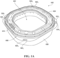
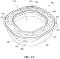
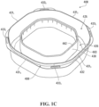
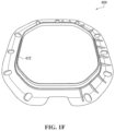
- FIGS 1A to 1G illustrate a cassette 400 and various elements of the cassette 400 in accordance with an embodiment of the invention.
- the cassette 400 includes a receptacle 408.
- the receptacle 408 defines a storage area 425 for holding an elongated tube of flexible material (not illustrated).
- the tube is collapsed (e.g., folded) to fit into the storage area 425.
- the tube would typically be round in cross-section but that is not essential.
- the tube could have other shapes as well, such as oval, rectangular, etc.
- the receptacle 408 is ring-shaped.
- ring-shape means a closed figure. Specific examples include an annular shape, an oval shape, a rectangular or square shape, hexagonal, octagonal, and/or any other polygonal closed figure shape.
- the receptacle 408 has an inner wall 430 defining a central, generally vertically extending opening 402.
- the opening is octagonal having four major sides (longer sides) and four minor sides (shorter sides).
- the receptacle 408 also includes an outer wall 432 that is laterally outwardly spaced apart from the inner wall 430.
- the outer wall 432 is also octagonal and has major sides and minor sides.
- a bottom portion 435 of the receptacle 408 connects the inner wall 430 and outer wall 432.
- the ring-shaped receptacle 408 defines the central opening 402, which extends along a generally vertical axis and also defines the storage area 425 for receiving the elongated tube of flexible material in a collapsed (e.g., folded) condition outward of the central opening 402.
- the ring shaped receptacle 408 has a clearance 488 that is located outwardly of an imaginary projection of the inner wall 430 extending downwardly along the vertical axis.
- the clearance 488 is formed by an oblique wall 412 connecting with the lower end portion 438 of the inner wall 430 and extending outwardly and downwardly thereform.
- the oblique wall 412 defines a corner 444 with the lower end portion of the inner wall 430 having an angle ⁇ substantially less than 270 degrees.
- the oblique wall 412 joins with the outer wall 432 through a bottom wall 440 that is substantially horizontal.
- the width of the bottom wall 440 is substantially less than the width of the oblique wall 412. In other embodiments, the width of the bottom wall 440 may be larger than the width of the oblique wall 412 or may be substantially equal. As illustrated, the oblique wall 412 forms a chamfer-like structure.
- the oblique wall 412 is provided on the full periphery of the receptacle 408 of the cassette 400, the oblique wall 412 may be partial (i.e., not on the full periphery of the opening 402 of the cassette 400) in other examples of implementation.
- the oblique wall 412 reduces the width of the storage area 425 near the bottom 435 of the storage area 425.
- the storage area 425 defines a first portion 482 that is located laterally outward of the oblique wall 412 and that vertically registers with the oblique wall 412 having a reduced width relative a second portion 481 of the storage area 425 located above the first portion 482 and above the oblique wall 412.
- the clearance 488 and the oblique wall 412 may be omitted and in such cases the bottom portion 435 comprises the bottom wall 440.
- the bottom portion would be formed by a horizontal flat wall only.
- the cassette 400 includes a cover 404 that is located above the storage area 425.
- the cover 404 is designed to maintain the elongated tube (not illustrated) into the storage area 425 while allowing the tube to be dispensed therefrom in a controlled fashion.
- the cover 404 has a shape that corresponds to the shape of the receptacle 408, that is it is octagonal, however that is not essential. It is possible to use a cover that is of a different shape than the shape of the receptacle 408.
- the cover 404 has a top portion 470 that merges with a central funnel-like structure 471.
- the funnel-like structure 471 has downwardly descending wall portion 472.
- the cover 404 is releasably attached to the top of the inner wall 430 of the receptacle 408 by the downwardly descending wall portion 472 by a mechanical fastener or otherwise. In other embodiments, the cover 404 is non-removable from the receptacle 408.
- the cover 404 also includes an outer peripheral wall 473 defined by an upturned lip 474.
- the lip 474 is laterally inwardly located from the upper peripheral edge 463 of the outer wall 432 of the receptacle 408 to define a gap 410 that extends along the entire periphery of the lip 474 to allow the accumulated tube in the storage area to be dispensed.
- the top peripheral edge of the outer peripheral wall 473 and the top peripheral edge 463 of the outer wall 432 define the gap 410, in this embodiment.
- the gap 410 may be defined around the top peripheral edge 462 of the inner wall 430 and in such cases a cover may be releasably or non-releasably attached to the top peripheral edge 463 of the outer wall 432 of the receptacle 408.
- the cover 404 may be omitted, and is such cases the gap 410 is defined by the top peripheral edges 463 462 of the outer wall 432 and the inner wall 430.
- the funnel-like structure 471 of the cover 404 and/or the upturned lip 474 may be omitted. It is appreciated that the cover 404 may be made in numerous ways in various embodiments of the invention.
- the shape of the cassette 400 is octagonal but that is a specific example of implementation.
- the cassette 400 has eight sides 431 1 431 2 431 3 431 4 433 1 433 2 433 3 433 4 .
- the four sides 433 1 433 2 433 3 433 4 are the ones located at the corner and may be referred to as the minor sides, while the other sides 431 1 431 2 431 3 431 4 may be referred to as the major sides.
- the minor sides 433 1 433 2 433 3 433 4 are shorter than the major sides 431 1 431 2 431 3 431 4 .
- each of four sides 433 1 , 433 2 , 433 3 , 433 4 may be longer in length in comparison to the length of each of the other four sides 431 1 , 431 2 , 431 3 , 431 4 . Yet, in other cases, the length of all of the sides 431 1 431 2 , 431 3 , 431 4 , 433 1 , 433 2 , 433 3 , 433 4 may be substantially equal in length.
- the cassette 400 may be generally square, rectangular, circular, hexagon shaped, oval shaped, any combination of the aforementioned shapes and/or any other suitable shape.
- the opening 402 is illustrated as a generally octagonal shape, the dimensions of the opening 402 may take on various sizes and shapes in examples of implementation.
- the opening 402 may be generally square, rectangular, circular, hexagon shaped, octagon shaped, any combination of the aforementioned shapes and/or any other suitable shape.
- the cover 404 may generally take the corresponding shape of the opening 402 on one side and the corresponding shape of the outer sidewall 432 on the other side.
- FIGS 2A and 2B illustrate a waste container 101 and various elements of the waste storage container 101 in which the cassette 400 described earlier is used, in accordance with an embodiment of the invention.
- the waste container 101 includes a base 10 and a main body 12 that engages with the base 10 to form a bin 24 for holding the waste enclosed in the tube.
- the bin 24 has outer walls defining an enclosure, which holds the waste-filled tube.
- the bin 24 includes two parts (i.e., the base 10 and the main body 12), in other embodiments, the bin 24 may be one piece.
- the waste storage container 101 also includes a closure assembly 17, which incorporates a cassette holder 14 and a top portion 16.
- FIGS 3A to 3D illustrate various elements of the closure assembly 17 in accordance with an embodiment of the invention.
- the closure assembly 17 engages with the upper end of the body 12 to form an upper wall of the bin 24 to hold the bin 24 closed.
- the closure assembly 17 defines a cassette holder 14 configured for receiving the cassette 400.
- the closure assembly 17 includes a top portion 16.
- Figures 4A and 4B illustrate the top portion 16.
- the top portion 16 is removably mountable on the cassette holder 14, as shown in Figure 2B .
- the top portion 16 of the closure assembly 17 defines a structure for guiding waste material to be disposed into the central opening 402 of the cassette 400.
- the structure for guiding the waste material is shaped as a funnel 206 having a wider opening at the top 241 that narrows toward a central opening 218 that registers with the central opening 402 of the cassette 400.
- the periphery of the bottom edge 242 of the funnel 206 defines the central opening 218.
- the funnel 206 and the central opening 402 form essentially a chute through which the waste to be disposed of is pushed into the bin 24.
- the chute may include a hinged, sliding or pivotable barrier to maintain the chute closed while no waste is being discarded.
- the barrier is configured to open when waste is to be inserted through chute.
- the shape of the central opening 218 generally matches the shape of the central opening 402 of the cassette 400 or is slightly smaller such as to avoid the cassette 400 from being exposed to waste material being pushed into the chute. If the central opening 218 of the top portion 16 of the closure mechanism 17 was made larger than the central opening 402 of the cassette 400, the cassette 400 would project into the path of the disposed waste which would be undesirable.
- a most preferred arrangement is one where an aperture, defined by the openings 402 and 218, into which the waste is being placed by the user is essentially vertical without any significant inward projections on which waste can collect.
- the opening 218 is illustrated as a generally octagonal, the opening 218 may take on various sizes and shapes, in other examples of implementation. For example, the opening 218 may be generally square, rectangular, circular, hexagon shaped, octagon shaped, any combination of the aforementioned shapes and/or any other suitable shape.
- the funnel 206 is pivotally mounted to the top portion 16.
- Figure 4A shows the case where the funnel 206 is in a closed position, overlying the cassette
- Figure 4B shows the case where the funnel 206 is in an open position.
- the pivotal connection allows opening the closure assembly 17 for removing a spent cassette 400 and installation of a new cassette (refill).
- the funnel 206 is hingedly attached to the top portion 16 by the hinge member 214 such that the funnel 206 can be pivoted; however in other cases, other mechanisms may be provided for attaching the funnel 206 to the top portion 16.
- the funnel 206 when closed down is configured to engage the cassette 400 such as to keep the cassette 400 firmly in place against motion forces resulting from a user pulling the tube and placing waste into it and also to provide some additional retention to the dispensing of the tube and avoid that too much tube length is being pulled (i.e., more than necessary).
- the lower side 216 of the funnel 206 has a structure designed to engage the cassette 400.
- the funnel 206 has a downward projection 249 that is configured to enter the gap 410 of the cassette 400 through which the tube is dispensed. In this fashion, the tube is constrained to slide against the projection 249 as it is being dispensed and requires some additional level of pulling force thus avoiding dispensing too much length.
- the downward projection 249 is a continuous wall portion 251 that penetrates the gap 410 over a significant portion of its length.
- the continuous wall portion 251 has the same general configuration as the gap of the cassette such as to mate with it.
- the continuous wall portion 251 engages five out of eight sides of the gap 410, but more less extent of engagement is possible.
- the wall 251 tapers upwardly at its ends.
- the depth of penetration of the downward projection 249 into the gap 410 is selected to account for a variable height of flexible tubing stack in the receptacle 408, as flexible tubing is being dispensed in use. In other words, the depth of penetration needs not be to much to prevent the funnel 206 of being closed when a new cassette, in which the flexible tubing stack is at its maximum.
- the wall 251 is spaced inwardly from the periphery of the funnel 206 to provide a flange 246 that extends continuously around the periphery of the funnel 206.
- the flange 246 is designed to further engage the cassette 400 and to hold it in place once the funnel 206 is closed, as it will be discussed below.
- the rim portion 22 is configured to matingly engage the cassette 400 such that the cassette 400 is securely held in place.
- the cassette 400 is suspended from the rim portion; in other words, the cassette 400 is not supported by its bottom.
- the rim portion 22 defines a hollow area 314 having an outer peripheral wall portion that is complementary to the shape of the cassette 400.
- the wall portion has a first pair of opposed cassette support elements and a second pair of opposed cassette support elements.
- the first and second pair of cassette support elements include inwardly extending projections 306 1 306 2 306 3 306 4 that are used to hold the cassette.
- the outer peripheral wall of the hollow area 314 of the cassette holder 14 is has a generally octagonal configuration, including the first pair of opposed cassette support elements 306 1 306 2 and the second pair of opposed cassette support elements 306 3 306 4 .
- the peripheral wall has generally straight sides 393, 393 2 393 3 393 4 that generally correspond in length to the major sides 431 1 431 2 431 3 431 4 of the cassette and corners 391, 391 2 391 3 391 4 that correspond in length generally to the minor sides 433 1 433 2 433 3 433 4 of the cassette 400.
- the generally straight sides are parallel in pairs, that is the sides 393 1 and 393 4 are substantially parallel with each other and the sides 393 2 and 393 3 are parallel with each other.
- the corners 391 1 391 2 391 391 4 are also parallel in pairs, that is the corners 391, and 391 4 are parallel with each other and the corners 391 3 and 391 2 are parallel with each other.
- the cassette 400' (a variant of the cassette 400) is shaped such that larger clearances 315 1 315 2 315 3 315 4 exist between the cassette 400 and the rim 22.
- the cassette 400 includes a plurality of projecting elements 502 1 502 2 502 3 502 4 that are configured to engage the projecting supports 306 1 306 2 306 3 306 4 of the cassette holder 14.
- the plurality of projecting elements 502 1 502 2 502 3 502 4 are provided in a spaced apart relationship, where the projecting elements 502 1 502 2 502 3 502 4 extend from a periphery of the cassette 400 and are configured to support the cassette 400 in the waste storage container 101.
- the plurality of projecting elements 502 1 502 2 502 3 502 4 lie in a common imaginary plane, which is generally horizontal.
- the projecting elements 502 1 502 2 502 3 502 4 are generally equally spaced around the periphery of the cassette 400.
- each of the projecting elements 502 1 502 2 502 3 502 4 has an extent in a peripheral direction of the cassette 400 that is significantly larger than a thickness of the projecting element 502 3 502 2 502 3 502 4 measured along the vertical axis.
- the plurality of projecting elements 502 1 502 2 502 3 502 4 is shown as four, in other examples of implementation, the number of projecting elements 502, 502 2 502 3 502 4 may be more or less than four.
- the plane from with plurality of projecting elements 502, 502 2 502 3 502 4 lie may not be a common imaginary plane and the direction of projection may vary from the horizontal plane (e.g., projects in an inclining or declining fashion from the horizontal plane).
- the projecting elements 502 1 502 2 502 3 502 4 are not equally spaced around the periphery of the cassette 400, but are provided in a staggered orientation.
- the projecting clements 502 1 502 2 502 3 502 4 are defined by a continuous lip 499 with extends outwardly from the outer wall.
- the lip 499 has a variable width along the periphery of the receptacle and it is less wide at the major sides 431 1 431 2 431 3 431 4 and wider at the minor sides 433 1 433 2 433 3 433 4 such as to create an interference with the projecting supports 306, 306 2 306 3 306 4 .
- the lip 499 that projects outwardly from the cassette 400 extends along at least a portion of the periphery of the cassette 400 and has a variable projection width.
- an interlock is provided between the projecting elements 502 1 502 2 502 3 502 4 and the projecting supports 306 1 306 2 306 3 306 4 .
- the interlock includes a male/female interconnection.
- the male part 308 1 308 2 308 3 308 4 of the interlock is formed on the projecting supports 306, 306 1 , 306 3 306 4 and the female part 504 1 504 2 504 3 504 4 on the projecting elements 502, 502 2 502 3 502 4 such that when the cassette 400 is placed in the opening 314 of the cassette holder 14, the male parts 308 1 308 2 308 3 308 4 will engage the female parts 504 1 504 2 504 3 504 4 .
- the male part 308, 308 2 308 3 308 4 of the interlock is formed on the projecting elements 502, 502 2 502 3 502 4 and the female part 504, 504 2 504 3 504 4 on the projecting supports 306 1 306 2 306 3 306 4 .
- the interlock is provided between each of the projecting elements 502 1 502 2 502 3 502 4 and the projecting supports 306 1 306 2 306 3 306 4 , in other embodiments, not all of the projecting elements 502 1 502 2 502 3 502 4 and the projecting supports 306 1 306 2 306 3 306 4 include the interlock.
- At least one of the projecting elements 502 1 502 2 502 3 502 4 includes a male or female interlocking component configured to engage a complementary male or female interlocking component in the waste storage container 101.
- the interlocking component of at least one of the projecting elements 502 1 502 2 502 3 502 4 is a female interlocking component.
- the male parts 308 1 308 2 308 3 308 4 can be made as tongues that extend generally parallel to the minor sides 433 1 433 2 433 3 433 4 and they are shorter than the minor sides 433 1 433 2 433 3 433 4 of the cassette 400.
- the female parts 504, 504 2 504 3 504 4 receive the tongues.
- the female parts 504 1 504 2 504 3 504 4 can be slots which are complementary to the tongues (as shown in Figures 3A to 3D ).
- the interlocking component of one or more of the projecting elements 502 1 502 2 502 3 502 4 is an elongated slot configured for receiving a male interlocking component in the waste storage container 101.
- the female parts 504 1 ' 504 2 ' 504 3 ' 504 4 ' can be cut outs or clearances that are larger than the tongues and simply clear the tongues (as shown in Figure 5A ).
- the projecting elements 502 1 502 2 502 3 502 4 are located closer to the upper end of the cassette 400 than to its bottom such that the cassette 400 cannot be installed upside down. If the cassette 400 is attempted to be installed upside down, the lip 499 defined by the projecting elements 502 1 502 2 502 3 502 4 will engage the projecting supports 306 1 306 2 306 3 306 4 but the funnel 206 will not be able to be closed which will make it clear to the user that the cassette 400 is improperly installed.
- the flange 246 of the funnel 206 rests on top of the male projecting parts 308 3 308 2 308 3 308 4 preventing the projecting elements 502, 502 2 502 3 502 4 to be lifted off the projecting supports 306 1 306 2 306 3 306 4 .
- the flange 246 will engage the tops of the tongues of the male projecting parts 308 1 308 2 308 3 308 4 .
- Another option is to provide in the flange 246 recesses (not illustrated) that register with the tongues of the male projecting parts 308 1 308 2 308 3 308 4 such that they are received in the recesses when the funnel 206 is closed. In this fashion, the flange 246 bears directly on the lip 499 defined by the projecting elements 502, 502 2 502 3 502 4 of the cassette 400 to bring even more stability.
- the male/female interlock engagement can obviously vary and may include rounded pins and complementary holes and any other combinations of shapes.
- the arrangement may also be such as to require the cassette 400 to be placed in a specific angular orientation, in other words, locate a specific projecting element of the cassette in a specific projecting support on the rim.
- the closure assembly 17 may also include a spring-biased lid 18, which is hingedly attached to the top portion 16 by the hinge member 214 such that the lid 18 can be opened to provide the user access to the funnel, for example to dispose of waste materials.
- An actuator 212 is shown in the form of a button which keeps the lid 18 closed (e.g., Figure 2A ). When a user actuates the actuator (e.g., pushes the button) this causes the lid 18 to move from a closed position (e.g., Figure 2A ) to an open position (e.g., Figure 4A ).
- FIG. 6 is a flowchart for a method 600 of replacing a cassette in accordance with an embodiment of the invention.
- the user takes a new cassette (refill) and removes the tear band 418, if equipped to open the gap 410 (step 602).
- the closure assembly 17 is opened by lifting the funnel 206 to expose the old cassette 400 (step 604).
- the old cassette 400 is removed (step 606) and a new one put in place (step 608).
- the lip 499 defined by the projecting elements 502, 502 2 502 3 502 4 of the cassette 400 rests on the projecting supports 306 1 306 2 306 3 306 4 and the male/female interlocks engage.
- the tube is prepared for use (e.g., a knot may be tied in the end portion to form a bag and is inserted into the opening 218 of the funnel 206 and into the enclosure of the bin 24) and the funnel 206 is closed (step 610).
- a refill can be considered that uses one or more components of the spent cassette.
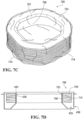
- a refill is shown in Figure 7A and 7B .
- the refill 701 has no receptacle 408, in other words the original receptacle 408 is being re-used.
- the refill 701 has a replacement cover 702 to which a length of elongated tubing 704 in an accumulated or pleated condition is attached to the cover 702.
- the pleats of the tube 704 can be retained to one another to prevent the tube 704 from unraveling before it is being installed in the old receptacle 408.
- This can be accomplished by a plurality of tear-away bands 705 that hold the tube against the cover 702.
- the cover 702 is put on the old receptacle 408 (after the old cover is removed) and the tear-away bands 705 are removed to release the tube 704, that can now be pulled out of the gap and used for receiving waste.
- FIG. 7C and 7D Another example, is that of refill 750 shown in Figures 7C and 7D .
- the refill 750 is provided without the receptacle 408, in other words the original receptacle 408 is also being re-used.
- the refill 750 has a tube support portion 756 having a cover part 754 with a depending vertical wall 756 that defines a tubular structure dimensioned to slip over the inner wall 430 of the original receptacle.
- a connecting element 752 engages the top peripheral edge 462 of the inner wall 430 of the receptacle 408 and to hold the refill 750 in place when installed in the receptacle 408.
- a layer of shrink-wrap 724 or other suitable material holds the tube 714 against the vertical wall 756.
- the shrink-wrap prevents the tube 714 from unraveling before it is being installed in the old receptacle 408. Once the refill 750 is put into the old receptacle 408 and the shrink-wrap 724 is removed, the cassette so re-loaded is ready for use.
- the shrink-wrap can be removed by providing a suitable tear-band (not illustrated).
- cassette 400 and the waste container 101 may be used to dispose of various waste materials including but not limited to disposable baby diapers, cat litter, animal feces, garbage, other soiled materials, or any other suitable waste materials/objects.
Landscapes
- Engineering & Computer Science (AREA)
- Mechanical Engineering (AREA)
- Refuse Receptacles (AREA)
Applications Claiming Priority (3)
| Application Number | Priority Date | Filing Date | Title |
|---|---|---|---|
| US201562175970P | 2015-06-15 | 2015-06-15 | |
| EP16741389.7A EP3307651B8 (de) | 2015-06-15 | 2016-06-14 | Kassette zur verwendung bei der entsorgung von abfallstoffen über ein langgestrecktes flexibles rohr |
| PCT/IB2016/053505 WO2016203370A2 (en) | 2015-06-15 | 2016-06-14 | Cassette and apparatus for use in disposing waste materials into an elongated flexible tube |
Related Parent Applications (2)
| Application Number | Title | Priority Date | Filing Date |
|---|---|---|---|
| EP16741389.7A Division-Into EP3307651B8 (de) | 2015-06-15 | 2016-06-14 | Kassette zur verwendung bei der entsorgung von abfallstoffen über ein langgestrecktes flexibles rohr |
| EP16741389.7A Division EP3307651B8 (de) | 2015-06-15 | 2016-06-14 | Kassette zur verwendung bei der entsorgung von abfallstoffen über ein langgestrecktes flexibles rohr |
Publications (2)
| Publication Number | Publication Date |
|---|---|
| EP4545430A2 true EP4545430A2 (de) | 2025-04-30 |
| EP4545430A3 EP4545430A3 (de) | 2025-05-14 |
Family
ID=56497810
Family Applications (2)
| Application Number | Title | Priority Date | Filing Date |
|---|---|---|---|
| EP25163809.4A Pending EP4545430A3 (de) | 2015-06-15 | 2016-06-14 | Kassette und vorrichtung zur verwendung bei der entsorgung von abfallstoffen in ein langgestrecktes flexibles rohr |
| EP16741389.7A Active EP3307651B8 (de) | 2015-06-15 | 2016-06-14 | Kassette zur verwendung bei der entsorgung von abfallstoffen über ein langgestrecktes flexibles rohr |
Family Applications After (1)
| Application Number | Title | Priority Date | Filing Date |
|---|---|---|---|
| EP16741389.7A Active EP3307651B8 (de) | 2015-06-15 | 2016-06-14 | Kassette zur verwendung bei der entsorgung von abfallstoffen über ein langgestrecktes flexibles rohr |
Country Status (7)
| Country | Link |
|---|---|
| US (2) | US10696476B2 (de) |
| EP (2) | EP4545430A3 (de) |
| CA (3) | CA2989524C (de) |
| ES (1) | ES3027009T3 (de) |
| HU (1) | HUE071156T2 (de) |
| PL (1) | PL3307651T3 (de) |
| WO (1) | WO2016203370A2 (de) |
Families Citing this family (18)
| Publication number | Priority date | Publication date | Assignee | Title |
|---|---|---|---|---|
| US12410005B2 (en) * | 2012-10-24 | 2025-09-09 | Munchkin, Inc. | Cassette for dispensing pleated tubing |
| USD1077510S1 (en) | 2019-11-06 | 2025-06-03 | Munchkin, Inc. | Cassette |
| CA2970656C (en) * | 2014-12-11 | 2024-01-09 | Munchkin, Inc. | Container for receving multiple flexible bag assemblies |
| JP1592679S (de) * | 2015-02-25 | 2017-12-11 | ||
| EP3408194A1 (de) * | 2016-01-28 | 2018-12-05 | Edgewell Personal Care Brands, LLC | Kassette mit kavität mit ungleichmässiger auskleidung |
| US10392188B1 (en) * | 2016-02-19 | 2019-08-27 | Joe L. Harrison | Nested liner assembly for a trash receptacle |
| EP4058381B1 (de) * | 2019-11-12 | 2024-08-07 | Kevin Bavendiek | Nachfüllkassette |
| USD943301S1 (en) * | 2020-04-22 | 2022-02-15 | Angelcare Canada Inc. | Film-dispensing cassette for garbage |
| USD947564S1 (en) * | 2020-07-20 | 2022-04-05 | Guangzhou Qianzhou Envi. Tech. Co., Ltd. | Film-dispensing cassette for garbage |
| GB2600912B (en) * | 2020-09-28 | 2023-04-26 | Sangenic International Ltd | Waste storage refill |
| EP3984916A1 (de) * | 2020-10-19 | 2022-04-20 | Venture Alliance Limited | Abfallentsorgungsvorrichtung |
| CN218877754U (zh) * | 2022-12-07 | 2023-04-18 | 深圳市杉川机器人有限公司 | 打包袋盒、打包模块及猫砂盆 |
| JP2026508107A (ja) * | 2023-01-27 | 2026-03-10 | エンジェルケア カナダ インコーポレイテッド | 廃棄物処分デバイス |
| GB2628147B (en) * | 2023-03-16 | 2025-04-16 | Unisort Ltd | Bin liner system |
| AU2024297274A1 (en) * | 2023-07-12 | 2026-02-05 | Angelcare Canada Inc. | Waste-disposal device |
| GB2633546A (en) * | 2023-07-26 | 2025-03-19 | Unisan Ltd | Waste receptacle |
| WO2025059386A1 (en) * | 2023-09-12 | 2025-03-20 | Munchkin, Inc. | Cassette for dispensing pleated tubing |
| CN223162449U (zh) * | 2024-08-27 | 2025-07-29 | 江苏中恒宠物用品股份有限公司 | 一种垃圾袋存储盒 |
Citations (1)
| Publication number | Priority date | Publication date | Assignee | Title |
|---|---|---|---|---|
| CA2640384A1 (en) | 2007-10-05 | 2009-04-05 | Les Developpements Angelcare Inc. | Cassette and apparatus for packing disposable objects into an elongated tube of flexible material |
Family Cites Families (104)
| Publication number | Priority date | Publication date | Assignee | Title |
|---|---|---|---|---|
| DE816342C (de) | 1948-10-02 | 1951-10-11 | Hans Sikora | Vorrichtung an Konservengefaessen zur Verhinderung des Abrutschens aufeinandergestellter Gefaesse |
| US3452368A (en) | 1966-10-07 | 1969-07-01 | Fts Corp | Portable waste disposer |
| US3534866A (en) | 1968-12-30 | 1970-10-20 | Shell Oil Co | Stacking and nesting bin box |
| US3547309A (en) | 1969-01-24 | 1970-12-15 | Chester County Mushroom Sales | Stackable and nestable plastic lugs |
| US3536192A (en) * | 1969-02-17 | 1970-10-27 | John R Couper | Container for incremental withdraw of tubular plastic |
| US3638827A (en) | 1969-06-12 | 1972-02-01 | T O Plastics Inc | Nestable tray |
| US3613943A (en) | 1969-12-31 | 1971-10-19 | Phillips Petroleum Co | Nesting and stacking container |
| US3746159A (en) | 1971-08-19 | 1973-07-17 | Coleman Co | Cartridge package for a sanitary toilet |
| DE2239880A1 (de) | 1972-08-14 | 1974-02-28 | Cordes Werner | Verfahren zur ablage und lagerung von muell und muellbehaelter zur durchfuehrung des verfahrens |
| US3888406A (en) | 1973-01-02 | 1975-06-10 | J Timothy Nippes | Trash disposal apparatus |
| US3853223A (en) | 1973-06-14 | 1974-12-10 | F Nowlain | Rope container |
| GB0114312D0 (en) | 2001-06-12 | 2001-08-01 | Sangenic International Ltd | Spool for a waste storage device |
| FR2425384A1 (fr) | 1978-05-12 | 1979-12-07 | Scido | Dispositif pour le conditionnement d'objets dans une gaine tubulaire continue et comprenant un mecanisme d'entrainement positif de la gaine |
| GB2176459A (en) | 1985-06-14 | 1986-12-31 | Grace W R & Co | Taped bag chain with cassette |
| GB8705120D0 (en) | 1987-03-05 | 1987-04-08 | Process Improvements Ltd | Packs of flexible tubing |
| EP0303517A1 (de) | 1987-08-13 | 1989-02-15 | van der Mescht, Leon | Vorrichtung zum Abgeben eines flexiblen Schlauches |
| GB8818365D0 (en) | 1988-08-02 | 1988-09-07 | Process Improvements Ltd | Cassette containing flexible tubing to be dispensed therefrom |
| GB2221889A (en) | 1988-08-17 | 1990-02-21 | Process Improvements Ltd | Device for packaging objects in flexible tubing |
| US4917263A (en) | 1988-12-09 | 1990-04-17 | Yaakov Korb | Household container assembly with adaptable lid for a plurality of bags |
| USD322030S (en) | 1988-12-22 | 1991-12-03 | Chumenti Vincent A | Combined tape dispenser and display package |
| US5337581A (en) | 1990-03-08 | 1994-08-16 | Gene Lott | Refrigerated waste container with germicidal lamp |
| US5117778A (en) | 1991-10-07 | 1992-06-02 | Imamura Alvin H | Moated animal feeding dish |
| JPH05146700A (ja) | 1991-11-29 | 1993-06-15 | Fujitsu General Ltd | 厨芥処理装置 |
| JPH05286503A (ja) | 1992-04-10 | 1993-11-02 | Fujitsu General Ltd | 厨芥処理装置 |
| JPH06183505A (ja) | 1992-12-18 | 1994-07-05 | Fujimori Kogyo Kk | ごみ処理用シャードフィルムカセット |
| DE9319683U1 (de) | 1993-12-21 | 1994-04-28 | Kreth Julius | Vorrichtung zum Verpacken von Abfällen |
| EP0772550A2 (de) | 1994-08-11 | 1997-05-14 | John C. Marrelli | Wiederverwendbarer kunststoffbehälter zur verpackung von einwegkunststoffmüllsäcken sowie verfahren zur verpackung |
| JP3042826B2 (ja) | 1995-02-21 | 2000-05-22 | キヤノン株式会社 | インクタンク、および該インクタンクを着脱自在に保持するホルダを備えたインクジェット記録装置 |
| GB2292725B (en) | 1994-08-26 | 1998-04-15 | Process Improvements 1989 Ltd | Apparatus for using packs of flexible tubing in packaging |
| USD381472S (en) | 1995-11-03 | 1997-07-22 | Anthony Catalano | Spill catching pet bowl |
| EP0861191B1 (de) * | 1995-11-17 | 2000-05-24 | Captiva Holding | Vorrichtung zum sammeln und einschliessen von krankenhausabfällen und hausmüll |
| US5947295A (en) | 1996-04-08 | 1999-09-07 | Lutin; Matthew | Liner dispenser for waste containers |
| US5632401A (en) | 1996-05-13 | 1997-05-27 | Hurd; John W. | Garbage container and liner dispensing system |
| US5699925A (en) | 1996-05-14 | 1997-12-23 | Petruzzi; Thomas G. | Interlocking stackable container storage system |
| GB9621864D0 (en) | 1996-10-21 | 1996-12-11 | Process Improvements 1989 Ltd | Apparatus for packaging packs of odorous waste in flexible tubing |
| US5813200A (en) * | 1996-12-17 | 1998-09-29 | Mondial Industries, Ltd. | Packaging and disposal system |
| WO1999020547A1 (en) | 1997-10-17 | 1999-04-29 | Gianni Tronchin | Container for waste collection provided with refillable dispenser of disposable continuous bags |
| GB9802738D0 (en) * | 1998-02-09 | 1998-04-08 | Sangenic International Ltd | Waste storage device |
| JP3256847B2 (ja) | 1998-08-20 | 2002-02-18 | 岩崎工業株式会社 | 屑入れ |
| US7002988B1 (en) | 1998-12-04 | 2006-02-21 | Tekelec | Methods and systems for communicating SS7 messages over packet-based network using transport adapter layer interface |
| US6116780A (en) | 1999-01-20 | 2000-09-12 | American Innotek, Inc. | Disposable toilet system |
| JP2000247401A (ja) | 1999-02-25 | 2000-09-12 | Biotech Research:Kk | 使用済み紙おむつ等貯留容器 |
| GB9908206D0 (en) | 1999-04-09 | 1999-06-02 | Sangenic International Limited | Waste storage device |
| EP1324919B1 (de) | 2000-09-07 | 2005-06-01 | Karl-Erik Wessmann | Vorrichtung zur getrennten abdichtung mehrerer objekte |
| US6370847B1 (en) | 2000-10-02 | 2002-04-16 | Tim Allan Nygaard Jensen | Sealable diaper-disposal system and method |
| US20020078665A1 (en) | 2000-12-21 | 2002-06-27 | Salman Nabil Enrique | Portable packaging device and method for forming individually packaged articles |
| US20020130060A1 (en) | 2001-03-16 | 2002-09-19 | Carson John P. | Packaging system |
| US7350663B2 (en) | 2001-04-10 | 2008-04-01 | Playtex Products, Inc. | Waste storage device |
| US20050044819A1 (en) | 2003-09-02 | 2005-03-03 | Chomik Richard S. | Waste storage device |
| KR20040014517A (ko) | 2001-05-02 | 2004-02-14 | 새니퀘스트 인더스트리즈 코포레이션 | 폐기물 처리 장치 |
| US7694493B2 (en) | 2001-05-02 | 2010-04-13 | Playtex Products, Inc. | Waste disposal device including a geared rotating cartridge |
| US7712285B2 (en) | 2001-05-02 | 2010-05-11 | Playtex Products, Inc. | Waste disposal device including a sensing mechanism for delaying the rotation of a cartridge |
| US8091325B2 (en) | 2001-05-02 | 2012-01-10 | Playtex Products, Inc. | Waste disposal device including a diaphragm for twisting a flexible tubing dispensed from a cartridge |
| US7146785B2 (en) | 2001-05-02 | 2006-12-12 | Stravitz David M | Waste disposal devices |
| US7617659B2 (en) | 2001-05-02 | 2009-11-17 | Playtex Products, Inc. | Waste disposal device including a cartridge movable by rollers |
| US7503159B2 (en) | 2001-05-02 | 2009-03-17 | Playtex Products, Inc. | Waste disposal device including an external actuation mechanism to operate a cartridge |
| US7434377B2 (en) | 2001-05-02 | 2008-10-14 | Playtex Products, Inc. | Waste disposal device including a rotatable geared rim to operate a cartridge |
| US7708188B2 (en) | 2001-05-02 | 2010-05-04 | Playtex Products, Inc. | Waste disposal device including a hamper accessible through a movable door |
| US7958704B2 (en) | 2001-05-02 | 2011-06-14 | Playtex Products, Inc. | Waste disposal device including a mechanism for scoring a flexible tubing dispensed from a cartridge |
| US7316100B2 (en) | 2001-05-02 | 2008-01-08 | Playtex Products, Inc. | Waste disposal device including a film cutting and sealing device |
| SE523546C2 (sv) | 2001-08-10 | 2004-04-27 | Danfo Ab | Foliekassett |
| CA2387183C (en) | 2001-12-31 | 2009-05-12 | Moniteurs Angelcare Inc. | Cassette for dispensing pleated tubing |
| CA2366435C (en) | 2002-01-02 | 2011-03-15 | Playtex Products, Inc. | Improved odor control cassette |
| JP2003241353A (ja) | 2002-02-13 | 2003-08-27 | Fuji Photo Film Co Ltd | 感光材料現像処理装置 |
| CA2482592C (en) | 2002-04-17 | 2008-02-19 | Playtex Products, Inc. | Composite trash container |
| WO2004011164A2 (en) | 2002-07-31 | 2004-02-05 | Stravitz David M | Waste disposal device |
| CA2441837A1 (en) | 2002-11-20 | 2004-05-20 | Les Developpements Angelcare Inc. | Apparatus for packing objects into an elongated tube |
| JP3774429B2 (ja) | 2002-11-27 | 2006-05-17 | 株式会社グリーンライフ | 廃棄物処理装置 |
| US7086569B2 (en) | 2003-01-06 | 2006-08-08 | Stravitz David M | All-purpose dispenser |
| US6672472B1 (en) | 2003-02-14 | 2004-01-06 | Elayne D. Rockwood | Soiled clothing container |
| AU2003900951A0 (en) | 2003-02-21 | 2003-03-13 | Julie Hautop | Sanitary napkin disposal assembly |
| US6941733B2 (en) | 2003-04-03 | 2005-09-13 | Playtex Products, Inc. | Waste disposal apparatus |
| JP2004358914A (ja) | 2003-06-06 | 2004-12-24 | Canon Inc | インクタンク |
| GB0324764D0 (en) | 2003-10-23 | 2003-11-26 | Sangenic International Ltd | Waste storage device |
| GB2409866A (en) | 2004-01-08 | 2005-07-13 | Medicart Int Ltd | Waste packaging system |
| US20050150804A1 (en) | 2004-01-13 | 2005-07-14 | Jing-Ji Chen | Device for preventing ants from entering containers |
| US6925781B1 (en) | 2004-02-03 | 2005-08-09 | Playtex Products, Inc. | Integrated cutting tool for waste disposal method and apparatus |
| US6993891B2 (en) | 2004-04-03 | 2006-02-07 | Bobbi Sue Richardson | Waste disposal system with flexible tubing |
| US6931684B1 (en) | 2004-06-16 | 2005-08-23 | Patricia H. W. Henegar | Bed having an integral refuse disposal system |
| GB2432779B (en) * | 2004-09-02 | 2008-05-14 | Playtex Products Inc | Waste disposal apparatus |
| US7861881B2 (en) | 2004-10-28 | 2011-01-04 | General Mills Cereals, Llc. | Removable overcap for microwaveable packaged good article |
| US7406814B2 (en) | 2005-04-25 | 2008-08-05 | International Refills Company Ltd. | Apparatus for packing disposable objects into an elongated tube of flexible material |
| CA2518325C (en) * | 2005-09-07 | 2013-01-22 | Les Developpements Angelcare Inc. | Apparatus for forming waste containing packs |
| DE202005015117U1 (de) | 2005-09-24 | 2007-02-15 | Melitta Haushaltsprodukte Gmbh & Co. Kg | Vorrichtung zum Verpacken von Hygieneartikeln |
| DE202005015081U1 (de) | 2005-09-24 | 2007-02-08 | Melitta Haushaltsprodukte Gmbh & Co. Kg | Kassette für einen Folienschlauch |
| US7775717B2 (en) | 2005-10-12 | 2010-08-17 | Sealed Air Corporation (Us) | Compacted bag configuration and method for making the same |
| DE202005020171U1 (de) | 2005-12-23 | 2006-06-08 | Gazo, Robert | Beutelspender |
| GB0622909D0 (en) | 2006-11-16 | 2006-12-27 | Sangenic International Ltd | Waste storage device |
| US20080272140A1 (en) * | 2007-05-04 | 2008-11-06 | Playtex Products, Inc. | Cassette for dispensing flexible tubing therefrom |
| DE202007009842U1 (de) | 2007-07-12 | 2008-11-20 | Sangenic International Ltd., Cramlington | Verbesserte Kassette für eine Abfallaufbewahrungsvorrichtung |
| DE202007019629U1 (de) | 2007-10-05 | 2014-11-20 | International Refills Co., Ltd. | Vorrichtung zur Verpackung von Wegwerfobjekten in einen länglichen Schlauch aus flexiblem Material |
| KR101353972B1 (ko) | 2008-05-19 | 2014-01-22 | 산제닉 인터내셔날 리미티드 | 폐기물 저장 장치 |
| TW201006652A (en) | 2008-08-01 | 2010-02-16 | Pegatron Corp | Injection molding machine and heat insulation structure of barrel thereof |
| GB0902471D0 (en) | 2009-02-13 | 2009-04-01 | Sangenic International Ltd | Waste storage device |
| KR20110027557A (ko) | 2009-09-10 | 2011-03-16 | 아프리카 칠드런즈 프로덕츠 가부시키가이샤 | 오물 처리 장치용 필름 수납 카세트 |
| US8635838B2 (en) * | 2009-10-30 | 2014-01-28 | Munchkin, Inc. | System for disposing waste packages such as diapers |
| CA2930991C (en) * | 2010-10-13 | 2017-06-06 | Les Developpements Angelcare Inc. | Film-dispensing cassette and rimmed bag for waste-disposal unit |
| WO2012109756A1 (en) * | 2011-02-18 | 2012-08-23 | Angelcare Development Inc. | Waste-disposal system for film-dispensing units |
| KR101704549B1 (ko) | 2011-06-10 | 2017-02-22 | 삼성전자주식회사 | 문자 입력 인터페이스 제공 방법 및 장치 |
| US9345369B2 (en) | 2011-08-23 | 2016-05-24 | Dry Flush Llc | Bagging toilet |
| AU2011101275A4 (en) | 2011-10-06 | 2011-11-17 | Darren James French | Waste bin liners |
| GB2505150A (en) | 2012-05-25 | 2014-02-26 | Sangenic International Ltd | Rollers to seal waste between film sheets |
| USD695541S1 (en) | 2012-10-24 | 2013-12-17 | Munchkin, Inc. | Cassette |
| KR102237146B1 (ko) | 2013-06-04 | 2021-04-08 | 버틀러 컨셉츠 리미티드 | 위생 용기 또는 그에 관련된 개량 |
-
2016
- 2016-06-14 PL PL16741389.7T patent/PL3307651T3/pl unknown
- 2016-06-14 EP EP25163809.4A patent/EP4545430A3/de active Pending
- 2016-06-14 CA CA2989524A patent/CA2989524C/en active Active
- 2016-06-14 ES ES16741389T patent/ES3027009T3/es active Active
- 2016-06-14 WO PCT/IB2016/053505 patent/WO2016203370A2/en not_active Ceased
- 2016-06-14 US US15/736,895 patent/US10696476B2/en active Active
- 2016-06-14 CA CA3074061A patent/CA3074061C/en active Active
- 2016-06-14 CA CA3074060A patent/CA3074060C/en active Active
- 2016-06-14 HU HUE16741389A patent/HUE071156T2/hu unknown
- 2016-06-14 EP EP16741389.7A patent/EP3307651B8/de active Active
-
2020
- 2020-05-21 US US16/880,469 patent/US11059667B2/en active Active
Patent Citations (1)
| Publication number | Priority date | Publication date | Assignee | Title |
|---|---|---|---|---|
| CA2640384A1 (en) | 2007-10-05 | 2009-04-05 | Les Developpements Angelcare Inc. | Cassette and apparatus for packing disposable objects into an elongated tube of flexible material |
Also Published As
| Publication number | Publication date |
|---|---|
| EP3307651B8 (de) | 2025-05-21 |
| WO2016203370A2 (en) | 2016-12-22 |
| CA3074061A1 (en) | 2016-12-22 |
| WO2016203370A3 (en) | 2017-02-09 |
| EP4545430A3 (de) | 2025-05-14 |
| CA3074061C (en) | 2020-10-20 |
| CA3074060C (en) | 2021-07-13 |
| EP3307651B1 (de) | 2025-04-09 |
| US11059667B2 (en) | 2021-07-13 |
| CA3074060A1 (en) | 2016-12-22 |
| PL3307651T3 (pl) | 2025-06-16 |
| EP3307651A2 (de) | 2018-04-18 |
| HUE071156T2 (hu) | 2025-08-28 |
| US20200277135A1 (en) | 2020-09-03 |
| CA2989524C (en) | 2020-10-20 |
| CA2989524A1 (en) | 2016-12-22 |
| US20180362250A1 (en) | 2018-12-20 |
| ES3027009T3 (en) | 2025-06-12 |
| EP3307651C0 (de) | 2025-04-09 |
| US10696476B2 (en) | 2020-06-30 |
Similar Documents
| Publication | Publication Date | Title |
|---|---|---|
| US11059667B2 (en) | Cassette and apparatus for use in disposing waste materials into an elongated flexible tube | |
| US10913626B2 (en) | Cassette for dispensing pleated tubing | |
| US10081489B2 (en) | Waste-disposal system for film-dispensing units | |
| CA3030263C (en) | Cassette and apparatus for packing disposable objects into an elongated tube of flexible material | |
| GB2526132A (en) | Suspension file storage container | |
| JP2005145542A (ja) | 摺り切り具付の蓋および蓋付の容器 | |
| HK40010654B (en) | Cassette for dispensing pleated tubing | |
| HK40010654A (en) | Cassette for dispensing pleated tubing |
Legal Events
| Date | Code | Title | Description |
|---|---|---|---|
| PUAI | Public reference made under article 153(3) epc to a published international application that has entered the european phase |
Free format text: ORIGINAL CODE: 0009012 |
|
| STAA | Information on the status of an ep patent application or granted ep patent |
Free format text: STATUS: REQUEST FOR EXAMINATION WAS MADE |
|
| REG | Reference to a national code |
Ref country code: DE Ref legal event code: R079 Free format text: PREVIOUS MAIN CLASS: B65B0067120000 Ipc: B65F0001060000 |
|
| PUAL | Search report despatched |
Free format text: ORIGINAL CODE: 0009013 |
|
| 17P | Request for examination filed |
Effective date: 20250314 |
|
| AC | Divisional application: reference to earlier application |
Ref document number: 3307651 Country of ref document: EP Kind code of ref document: P |
|
| AK | Designated contracting states |
Kind code of ref document: A2 Designated state(s): AL AT BE BG CH CY CZ DE DK EE ES FI FR GB GR HR HU IE IS IT LI LT LU LV MC MK MT NL NO PL PT RO RS SE SI SK SM TR |
|
| AK | Designated contracting states |
Kind code of ref document: A3 Designated state(s): AL AT BE BG CH CY CZ DE DK EE ES FI FR GB GR HR HU IE IS IT LI LT LU LV MC MK MT NL NO PL PT RO RS SE SI SK SM TR |
|
| RIC1 | Information provided on ipc code assigned before grant |
Ipc: B65B 67/12 20060101ALI20250404BHEP Ipc: B65F 1/06 20060101AFI20250404BHEP |