EP4545355A2 - Kindersitz - Google Patents
Kindersitz Download PDFInfo
- Publication number
- EP4545355A2 EP4545355A2 EP25164479.5A EP25164479A EP4545355A2 EP 4545355 A2 EP4545355 A2 EP 4545355A2 EP 25164479 A EP25164479 A EP 25164479A EP 4545355 A2 EP4545355 A2 EP 4545355A2
- Authority
- EP
- European Patent Office
- Prior art keywords
- seat
- end part
- child
- sidewalls
- seat shell
- Prior art date
- Legal status (The legal status is an assumption and is not a legal conclusion. Google has not performed a legal analysis and makes no representation as to the accuracy of the status listed.)
- Pending
Links
Images




Classifications
-
- B—PERFORMING OPERATIONS; TRANSPORTING
- B60—VEHICLES IN GENERAL
- B60N—SEATS SPECIALLY ADAPTED FOR VEHICLES; VEHICLE PASSENGER ACCOMMODATION NOT OTHERWISE PROVIDED FOR
- B60N2/00—Seats specially adapted for vehicles; Arrangement or mounting of seats in vehicles
- B60N2/24—Seats specially adapted for vehicles; Arrangement or mounting of seats in vehicles for particular purposes or particular vehicles
- B60N2/26—Seats specially adapted for vehicles; Arrangement or mounting of seats in vehicles for particular purposes or particular vehicles for children
- B60N2/28—Seats readily mountable on, and dismountable from, existing seats or other parts of the vehicle
- B60N2/2821—Seats readily mountable on, and dismountable from, existing seats or other parts of the vehicle having a seat and a base part
- B60N2/2827—Seats readily mountable on, and dismountable from, existing seats or other parts of the vehicle having a seat and a base part part of the base being supported by the seat sub-frame
-
- B—PERFORMING OPERATIONS; TRANSPORTING
- B60—VEHICLES IN GENERAL
- B60N—SEATS SPECIALLY ADAPTED FOR VEHICLES; VEHICLE PASSENGER ACCOMMODATION NOT OTHERWISE PROVIDED FOR
- B60N2/00—Seats specially adapted for vehicles; Arrangement or mounting of seats in vehicles
- B60N2/24—Seats specially adapted for vehicles; Arrangement or mounting of seats in vehicles for particular purposes or particular vehicles
- B60N2/26—Seats specially adapted for vehicles; Arrangement or mounting of seats in vehicles for particular purposes or particular vehicles for children
- B60N2/28—Seats readily mountable on, and dismountable from, existing seats or other parts of the vehicle
- B60N2/2821—Seats readily mountable on, and dismountable from, existing seats or other parts of the vehicle having a seat and a base part
-
- B—PERFORMING OPERATIONS; TRANSPORTING
- B60—VEHICLES IN GENERAL
- B60N—SEATS SPECIALLY ADAPTED FOR VEHICLES; VEHICLE PASSENGER ACCOMMODATION NOT OTHERWISE PROVIDED FOR
- B60N2/00—Seats specially adapted for vehicles; Arrangement or mounting of seats in vehicles
- B60N2/24—Seats specially adapted for vehicles; Arrangement or mounting of seats in vehicles for particular purposes or particular vehicles
- B60N2/26—Seats specially adapted for vehicles; Arrangement or mounting of seats in vehicles for particular purposes or particular vehicles for children
- B60N2/28—Seats readily mountable on, and dismountable from, existing seats or other parts of the vehicle
- B60N2/2821—Seats readily mountable on, and dismountable from, existing seats or other parts of the vehicle having a seat and a base part
- B60N2/2824—Seats readily mountable on, and dismountable from, existing seats or other parts of the vehicle having a seat and a base part part of the base being supported by the vehicle frame
-
- B—PERFORMING OPERATIONS; TRANSPORTING
- B60—VEHICLES IN GENERAL
- B60N—SEATS SPECIALLY ADAPTED FOR VEHICLES; VEHICLE PASSENGER ACCOMMODATION NOT OTHERWISE PROVIDED FOR
- B60N2/00—Seats specially adapted for vehicles; Arrangement or mounting of seats in vehicles
- B60N2/24—Seats specially adapted for vehicles; Arrangement or mounting of seats in vehicles for particular purposes or particular vehicles
- B60N2/26—Seats specially adapted for vehicles; Arrangement or mounting of seats in vehicles for particular purposes or particular vehicles for children
- B60N2/28—Seats readily mountable on, and dismountable from, existing seats or other parts of the vehicle
- B60N2/2839—Seats readily mountable on, and dismountable from, existing seats or other parts of the vehicle having a front guard or barrier
-
- B—PERFORMING OPERATIONS; TRANSPORTING
- B60—VEHICLES IN GENERAL
- B60N—SEATS SPECIALLY ADAPTED FOR VEHICLES; VEHICLE PASSENGER ACCOMMODATION NOT OTHERWISE PROVIDED FOR
- B60N2/00—Seats specially adapted for vehicles; Arrangement or mounting of seats in vehicles
- B60N2/24—Seats specially adapted for vehicles; Arrangement or mounting of seats in vehicles for particular purposes or particular vehicles
- B60N2/26—Seats specially adapted for vehicles; Arrangement or mounting of seats in vehicles for particular purposes or particular vehicles for children
- B60N2/28—Seats readily mountable on, and dismountable from, existing seats or other parts of the vehicle
- B60N2/2851—Seats readily mountable on, and dismountable from, existing seats or other parts of the vehicle provided with head-rests
-
- B—PERFORMING OPERATIONS; TRANSPORTING
- B60—VEHICLES IN GENERAL
- B60N—SEATS SPECIALLY ADAPTED FOR VEHICLES; VEHICLE PASSENGER ACCOMMODATION NOT OTHERWISE PROVIDED FOR
- B60N2/00—Seats specially adapted for vehicles; Arrangement or mounting of seats in vehicles
- B60N2/24—Seats specially adapted for vehicles; Arrangement or mounting of seats in vehicles for particular purposes or particular vehicles
- B60N2/26—Seats specially adapted for vehicles; Arrangement or mounting of seats in vehicles for particular purposes or particular vehicles for children
- B60N2/28—Seats readily mountable on, and dismountable from, existing seats or other parts of the vehicle
- B60N2/2869—Seats readily mountable on, and dismountable from, existing seats or other parts of the vehicle rotatable about a vertical axis
-
- B—PERFORMING OPERATIONS; TRANSPORTING
- B60—VEHICLES IN GENERAL
- B60N—SEATS SPECIALLY ADAPTED FOR VEHICLES; VEHICLE PASSENGER ACCOMMODATION NOT OTHERWISE PROVIDED FOR
- B60N2/00—Seats specially adapted for vehicles; Arrangement or mounting of seats in vehicles
- B60N2/24—Seats specially adapted for vehicles; Arrangement or mounting of seats in vehicles for particular purposes or particular vehicles
- B60N2/26—Seats specially adapted for vehicles; Arrangement or mounting of seats in vehicles for particular purposes or particular vehicles for children
- B60N2/28—Seats readily mountable on, and dismountable from, existing seats or other parts of the vehicle
- B60N2/2872—Seats readily mountable on, and dismountable from, existing seats or other parts of the vehicle provided with side rests
-
- B—PERFORMING OPERATIONS; TRANSPORTING
- B60—VEHICLES IN GENERAL
- B60N—SEATS SPECIALLY ADAPTED FOR VEHICLES; VEHICLE PASSENGER ACCOMMODATION NOT OTHERWISE PROVIDED FOR
- B60N2/00—Seats specially adapted for vehicles; Arrangement or mounting of seats in vehicles
- B60N2/24—Seats specially adapted for vehicles; Arrangement or mounting of seats in vehicles for particular purposes or particular vehicles
- B60N2/26—Seats specially adapted for vehicles; Arrangement or mounting of seats in vehicles for particular purposes or particular vehicles for children
- B60N2/28—Seats readily mountable on, and dismountable from, existing seats or other parts of the vehicle
- B60N2/2887—Fixation to a transversal anchorage bar, e.g. isofix
-
- B—PERFORMING OPERATIONS; TRANSPORTING
- B60—VEHICLES IN GENERAL
- B60N—SEATS SPECIALLY ADAPTED FOR VEHICLES; VEHICLE PASSENGER ACCOMMODATION NOT OTHERWISE PROVIDED FOR
- B60N2/00—Seats specially adapted for vehicles; Arrangement or mounting of seats in vehicles
- B60N2/90—Details or parts not otherwise provided for
- B60N2/995—Lower-leg-rests, e.g. calf-rests
Definitions
- the present invention relates to child safety seats.
- a child safety seat is typically used in an automobile vehicle to properly restrain a child in the event of accidental collision.
- the installation of a child safety seat in a rearward facing position can offer better protection because it allows the collision energy to be dispersed across a larger area of the child's body (i.e., the child's torso and head).
- safety experts and car seat manufacturers usually recommend to seat a child in the rearward facing position till the age of 2 years. As the child grows older, the child safety seat may be installed in the forward facing position.
- Some existing child safety seats allow to rotationally adjust a child seat between the rearward facing position and the forward facing position, and can further set the child seat in a sideways facing position for facilitating retrieval or placement of a child.
- the support base of the child safety seat is attached on a vehicle seat at a location that is usually not distant from the vehicle door, the child seat may adversely collide against the vehicle door when it rotates toward the sideways facing position.
- the present application describes a child safety seat that is more flexibly adjustable and can offer a more convenient use.
- a child seat includes a seat shell, and a retractable front end part rotatable relative to the seat shell between a retracted position and a deployed position.
- the seat shell has a front end, a seat portion and two sidewalls.
- the front end has an opening.
- Each of the two sidewalls has an inner cavity, the two sidewalls respectively protruding at a left and a right side of the seat portion, an interior space for receiving a child being defined at least partially between the two sidewalls.
- the front end part has a transversal portion and two side portions connected with the transversal portion, the transversal portion extending along a width direction of the seat shell, and the two side portions being respectively connected pivotally with the two sidewalls of the seat shell.
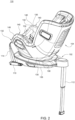
- FIGS. 1-3 are perspective views illustrating an embodiment of a child safety seat 100 in different positions.
- the child safety seat 100 includes a support base 102, and a child seat 104 disposed on the support base 102.
- the support base 102 is adapted to be installed on a vehicle seat, and can provide stable support for the child safety seat 100.
- the support base 102 can have a suitable structure for positioning the child seat 104 on the support base 102 in different orientations, such as a forward facing position shown in FIG. 1 , a rearward facing position shown in FIG. 2 , and a sideways facing position shown in FIG. 3 .
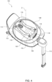
- FIG. 4 is a perspective view illustrating the support base 102.
- the support base 102 can include a shell body 106, a rotary platform 108, two latch devices 110 and a support leg 112.
- the shell body 106 can have an end forming a support panel 114 protruding upward.
- the two latch devices 110 can be assembled with the shell body 106, and can be disposed at a left and a right side of the shell body 106 adjacent to the support panel 114.
- the rotary platform 108 is pivotally connected with the shell body 106 about a pivot axis Z, and is adapted to receive the installation of the child seat 104.
- the pivot axis Z can vertically pass through the rotary platform 108, and can extend vertically or slightly tilted an angle (e.g., about 10 degrees to about 15 degrees) relative to a vertical axis.
- the rotary platform 108 can be provided with a plurality of latches 116 that are operatively connected with a release actuator 118. When the child seat 104 is installed on the rotary platform 108, the latches 116 can engage with the child seat 104 so that the child seat 104 and the rotary platform 108 are locked to each other.
- the release actuator 118 is operable to cause the latches 116 to move and disengage from the child seat 104 for removing the child seat 104 from the rotary platform 108.
- the rotary platform 108 can have a protruding portion 120, and four latches 116 can be provided on the protruding portion 120.
- FIG. 1 illustrates the child seat 104 and the rotary platform 108 in a forward facing position
- FIG. 2 illustrates the child seat 104 and the rotary platform 108 in a rearward facing position
- FIG. 3 illustrates the child seat 104 and the rotary platform 108 in a sideways facing position.
- a child When the child safety seat 100 is installed in the rearward facing position on a vehicle seat, a child can sit on the child seat 104 facing the seatback of the vehicle seat. When the child safety seat 100 is set in the sideways facing position, a child can sit on the child seat 104 facing a door of the vehicle.
- An angular displacement between the forward facing position and the sideways facing position can be about 90 degrees, and an angular displacement between the rearward facing position and the sideways facing position can also be about 90 degrees.
- the support base 102 may include a plurality of latching parts (not shown) for locking the child seat 104 and the rotary platform 108 in any of the forward facing position, the rearward facing position and the sideways facing position.
- the shell body 106 can be assembled with a plurality of latching parts operable to move upward for locking engagement with the rotary platform 108 and downward for disengaging from the rotary platform 108.
- the seat shell 130 can have a front end 134, a seat portion 136, a backrest portion 138 and two sidewalls 140.
- the seat portion 136 can extend between the front end 134 and the backrest portion 138, and the two sidewalls 140 can respectively protrude upward from the seat portion 136 at a left and a right side thereof.
- An interior space of the seat shell 130 suitable for receiving a child can be defined at least partially between the two sidewalls 140.
- Each sidewall 140 can have a hollow structure, which can include two opposite sidewall surfaces 142 and 144, a sidewall edge 146, and an inner cavity 148 (better shown in FIGS. 6-8 ) between the two sidewall surfaces 142 and 144. More specifically, the sidewall surface 142 can face the interior space of the seat shell 130, and the sidewall surface 144 can face an outer side of the seat shell 130.
- the sidewall edge 146 can be located above the seat portion 136, can be respectively connected with the two sidewall surfaces 142 and 144, and can extend to the front end 134 of the seat shell 130 with an inclination so that a front portion of the sidewall edge 146 can face forward.
- the inner cavity 148 of the sidewall 140 can be delimited at least partially by the two sidewall surfaces 142 and 144 and the sidewall edge 146.
- the front end 134 of the seat shell 130 can have an opening 150, which can extend transversally relative to the seat shell 130 and can be respectively connected with the inner cavities 148 of the two sidewalls 140.
- the front end part 132 can be pivotally connected with the seat shell 130, whereby the front end part 132 can rotate relative to the seat shell 130 between a deployed position and a retracted position. In the deployed position, the front end part 132 can extend outside the opening 150, and can project forward and downward. In the retracted position, the front end part 132 can be stowed and received at least partially inside the opening 150.
- the front end part 132 is thereby pivotally connected with the two sidewalls 140 about a pivot axis Y defined by the pivot shafts 158, which can be located above the seat portion 136.
- Each side portion 154 can have a width that is smaller than a width of the inner cavity 148 at a location adjacent to the sidewall 140, whereby the side portion 154 can be retracted at least partially into the inner cavity 148 of the sidewall 140 when the front end part 132 is in the retracted position.
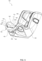
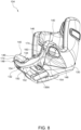
- FIG. 5 illustrates the front end part 132 of the child seat 104 in the deployed position.
- the transversal portion 152 of the front end part 132 can extend outside the opening 150 of the seat shell 130 and can be positioned in front of the seat portion 136.
- each side portion 154 of the front end part 132 can form a smooth profile extension relative to the sidewall 140 adjacent thereto that projects forward and downward from the opening 150.
- each side portion 154 can have a front surface 160 that inclines forward and downward and forms a generally smooth profile extension from the sidewall edge 146 of the sidewall 140 adjacent thereto.
- the front end part 132 can provide support for the feet or legs of a child in the deployed position.
- FIG. 8 illustrates the front end part 132 of the child seat 104 in the retracted position.
- the transversal portion 152 of the front end part 132 can be stowed and received at least partially inside the opening 150 of the seat shell 130, and more particularly can be positioned in a hollow interior of the seat portion 136 below an upper surface 136A of the seat portion 136.
- the two side portions 154 of the front end part 132 can be respectively received at least partially inside the inner cavities 148 of the two sidewalls 140, whereby the front surface 160 of each side portion 154 can form an angle with respect to the sidewall edge 146 of the sidewall 140 adjacent thereto.
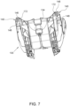
- FIG. 7 is a perspective view illustrating some inner construction details of the seat shell 130. For the sake of clarity, FIG. 7 omits the representation of the front end part 132.
- the child seat 104 can further include a latching mechanism 162 for locking the front end part 132 in the deployed position.
- the latching mechanism 162 can include two latches 164, two springs 166, a release actuator 168 and two cables 170.
- the two latches 164 can be respectively connected with the coupling ends 156 of the two side portions 154, and can move relative to the front end part 132 to engage with or disengage from the seat shell 130.
- each latch 134 can engage with a locking opening 172 provided in the seat shell 130 for locking the front end part 132 in the deployed position, wherein the locking opening 172 can be exemplarily placed inside the inner cavity 148 of the sidewall 140.
- each latch 164 can be slidably connected with the coupling end 156 of the side portion 154 associated therewith, and can slide relative to the front end part 132 to engage with or disengage from the seat shell 130.
- the two springs 166 can be respectively connected with the two latches 164, and can respectively bias the two latches 164 to move for engaging with the seat shell 130.
- the release actuator 168 can be assembled with the front end part 132, and can be respectively connected with the two latches 164 via the two cables 170. According to an example of construction, the release actuator 168 can be provided on the transversal portion 152 of the front end part 132. The release actuator 168 is operable by a caregiver to urge the two latches 164 to move and disengage from the seat shell 130, whereby the front end part 132 can be unlocked for adjustment between the deployed position and the retracted position.
- the latching mechanism 162 can further be configured to lock the front end part 132 in the retracted position.
- each latch 164 can engage with another locking opening 174 provided in the seat shell 130 for locking the front end part 132 in the retracted position.
- the locking opening 174 can be exemplarily provided on the sidewall edge 146.
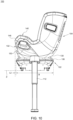
- FIG. 9 is a schematic view illustrating the child safety seat 100 with the seat shell 130 in the sideways facing position and the front end part 132 in the deployed position
- FIG. 10 is a schematic view illustrating the child safety seat 100 with the seat shell 130 in the sideways facing position and the front end part 132 in the retracted position.
- the front end part 132 when the seat shell 130 is in the sideways facing position on the support base 102 and the front end part 132 in the deployed position, the front end part 132 can sideways protrude a distance L1 from the support base 102. More specifically, an image projection of the front end part 132 on a bottom plane P of the support base 102 can protrude the distance L1 from an image projection B of the support base 102 on the bottom plane P.
- the front end part 132 when the seat shell 130 is in the sideways facing position on the support base 102 and the front end part 132 in the retracted position, the front end part 132 can sideways protrude a distance L2 from the support base 102, wherein the distance L2 can be substantially smaller than the distance L1 because the transversal portion 152 of the front end part 132 can be generally positioned in the hollow interior of the seat portion 136. According to an example of construction, the distance L2 can be equal to or smaller than about half the distance L1.
- an image projection of the front end part 132 on the bottom plane P of the support base 102 can be within the boundary of the image projection B of the support base 102 on the bottom plane P when the seat shell 130 is in the sideways facing position on the support base 102 and the front end part 132 in the retracted position. Accordingly, when the child safety seat 100 is used inside a vehicle, a caregiver can first adjust the front end part 132 to the retracted position, and then rotate the child seat 104 from the forward or rearward facing position to the sideways facing position for retrieving a child from the child seat 104 or placing a child on the child seat 104. With the front end part 132 in the retracted position, collision between the child seat 104 (in particular the front end part 132 thereof) and a door of the vehicle can be prevented as the child seat 104 rotates to the sideways facing position.
- Advantages of the structures described herein include the ability to provide a child safety seat that is adjustable to different orientations as needed and has a front end part retractable to prevent undesirable interference with a vehicle environment during the adjustment of the child safety seat. Accordingly, the child safety seat can be more flexible and convenient in use.
Landscapes
- Engineering & Computer Science (AREA)
- Aviation & Aerospace Engineering (AREA)
- Transportation (AREA)
- Mechanical Engineering (AREA)
- Health & Medical Sciences (AREA)
- Child & Adolescent Psychology (AREA)
- General Health & Medical Sciences (AREA)
- Seats For Vehicles (AREA)
Applications Claiming Priority (3)
| Application Number | Priority Date | Filing Date | Title |
|---|---|---|---|
| CN201911396862.XA CN113119820B (zh) | 2019-12-30 | 2019-12-30 | 儿童安全座椅 |
| EP22205101.3A EP4155122B1 (de) | 2019-12-30 | 2020-12-21 | Kindersitz |
| EP20216156.8A EP3845412B1 (de) | 2019-12-30 | 2020-12-21 | Kindersicherheitssitz |
Related Parent Applications (3)
| Application Number | Title | Priority Date | Filing Date |
|---|---|---|---|
| EP22205101.3A Division-Into EP4155122B1 (de) | 2019-12-30 | 2020-12-21 | Kindersitz |
| EP22205101.3A Division EP4155122B1 (de) | 2019-12-30 | 2020-12-21 | Kindersitz |
| EP20216156.8A Division EP3845412B1 (de) | 2019-12-30 | 2020-12-21 | Kindersicherheitssitz |
Publications (2)
| Publication Number | Publication Date |
|---|---|
| EP4545355A2 true EP4545355A2 (de) | 2025-04-30 |
| EP4545355A3 EP4545355A3 (de) | 2025-08-13 |
Family
ID=73856452
Family Applications (3)
| Application Number | Title | Priority Date | Filing Date |
|---|---|---|---|
| EP25164479.5A Pending EP4545355A3 (de) | 2019-12-30 | 2020-12-21 | Kindersitz |
| EP22205101.3A Active EP4155122B1 (de) | 2019-12-30 | 2020-12-21 | Kindersitz |
| EP20216156.8A Active EP3845412B1 (de) | 2019-12-30 | 2020-12-21 | Kindersicherheitssitz |
Family Applications After (2)
| Application Number | Title | Priority Date | Filing Date |
|---|---|---|---|
| EP22205101.3A Active EP4155122B1 (de) | 2019-12-30 | 2020-12-21 | Kindersitz |
| EP20216156.8A Active EP3845412B1 (de) | 2019-12-30 | 2020-12-21 | Kindersicherheitssitz |
Country Status (8)
| Country | Link |
|---|---|
| US (3) | US11485258B2 (de) |
| EP (3) | EP4545355A3 (de) |
| JP (3) | JP7234197B2 (de) |
| KR (2) | KR102505487B1 (de) |
| CN (2) | CN117068012A (de) |
| ES (2) | ES2937974T3 (de) |
| TW (2) | TWI831621B (de) |
| WO (1) | WO2021136714A1 (de) |
Families Citing this family (5)
| Publication number | Priority date | Publication date | Assignee | Title |
|---|---|---|---|---|
| CN117068012A (zh) * | 2019-12-30 | 2023-11-17 | 宝钜瑞士股份有限公司 | 儿童安全座椅 |
| CN118596960A (zh) * | 2021-01-29 | 2024-09-06 | 宝钜瑞士股份有限公司 | 婴儿载具 |
| CN115123033B (zh) * | 2022-05-05 | 2024-04-05 | 好孩子儿童用品有限公司 | 一种安全座椅 |
| WO2023242056A2 (en) * | 2022-06-13 | 2023-12-21 | Wonderland Switzerland Ag | Seat angle adjustment mechanism, support plate, and child safety seat |
| US11701985B1 (en) * | 2022-09-10 | 2023-07-18 | Ken Cabral | Pivoting car seat mount |
Family Cites Families (29)
| Publication number | Priority date | Publication date | Assignee | Title |
|---|---|---|---|---|
| US707859A (en) * | 1900-11-15 | 1902-08-26 | Roland A Mills | Hand tenoning-machine. |
| DE3900906A1 (de) * | 1988-01-14 | 1990-07-26 | Richard Ambros | Universal- automobilsitz fuer kleine und grosse insassen, insbesondere mitinsassen |
| JPH01111394A (ja) | 1987-10-23 | 1989-04-28 | Nec Corp | 半導体レーザ |
| JPH0433144Y2 (de) * | 1989-09-21 | 1992-08-10 | ||
| US5505519A (en) * | 1994-09-29 | 1996-04-09 | Natt; Theresa A. | Leg rest attachments for child car seats |
| US6068335A (en) | 1997-09-11 | 2000-05-30 | Cosco, Inc. | Retainer |
| GB9824728D0 (en) * | 1998-11-11 | 1999-01-06 | Britax Roemer Kindersicherheit Gmbh | Child safety seat |
| JP2000301970A (ja) * | 1999-04-20 | 2000-10-31 | Riiman Kk | チャイルドシート |
| US7066536B2 (en) * | 2002-02-11 | 2006-06-27 | Graco Children's Products Inc. | Child seat |
| US7073859B1 (en) * | 2004-08-19 | 2006-07-11 | Pamela S. Wilson | Pivotable child seat for use in a vehicle |
| EP1683443B1 (de) * | 2005-01-19 | 2012-02-22 | Aisin Seiki Kabushiki Kaisha | Ottoman |
| US7673934B2 (en) * | 2007-06-26 | 2010-03-09 | Wonderland Nurserygoods Co., Ltd. | Dual purpose high chair |
| US20090224584A1 (en) * | 2008-03-04 | 2009-09-10 | Gm Global Technology Operations, Inc. | Active material actuated seat base extender |
| US8348337B2 (en) | 2010-03-17 | 2013-01-08 | Britax Child Safety, Inc. | Child safety seat with energy absorbing apparatus |
| DE102011013373B4 (de) * | 2011-03-09 | 2017-07-13 | Robby Sacher | Säuglingslagerungssystem zur schwenkbaren Lagerung in einem Kraftfahrzeug und außerhalb davon |
| CN203126572U (zh) * | 2013-02-22 | 2013-08-14 | 宝钜(中国)儿童用品有限公司 | 汽车安全座椅 |
| PL2865562T3 (pl) * | 2013-10-23 | 2019-01-31 | Wonderland Switzerland Ag | Dziecięcy fotelik bezpieczeństwa |
| JP6542633B2 (ja) * | 2015-10-05 | 2019-07-10 | アップリカ・チルドレンズプロダクツ合同会社 | チャイルドシート |
| CN106671836B (zh) | 2015-11-06 | 2020-04-03 | 宝钜儿童用品香港股份有限公司 | 调整机构及具有该调整机构的儿童安全座椅 |
| US10322651B2 (en) * | 2016-06-14 | 2019-06-18 | Wonderland Switzerland Ag | Child safety seat |
| US10464450B1 (en) * | 2016-09-12 | 2019-11-05 | Steven B. Peterson | Appendage support for child seat |
| KR101850832B1 (ko) * | 2016-09-13 | 2018-04-20 | 주식회사 쁘레베베 | 카시트의 회전장치 |
| US10227022B2 (en) * | 2016-09-20 | 2019-03-12 | Toyota Boshoku Kabushiki Kaisha | Tilt arm for seat and vehicle seat |
| US10272804B2 (en) * | 2016-11-08 | 2019-04-30 | Wonderland Switzerland Ag | Child safety seat |
| US10688892B2 (en) * | 2017-03-17 | 2020-06-23 | Wonderland Switzerland Ag | Child safety seat |
| US10479306B2 (en) * | 2017-08-25 | 2019-11-19 | Ford Global Technologies, Llc | Restraint bar for vehicle seating assembly |
| CA3023122C (en) * | 2017-11-08 | 2020-10-27 | Britax Child Safety, Inc. | Multi-position anti-rebound bar |
| CN110497826B (zh) * | 2019-09-27 | 2022-05-24 | 创是实业(香港)有限公司 | 安全座椅底座操控组件、安全座椅底座、套件和操控方法 |
| CN117068012A (zh) | 2019-12-30 | 2023-11-17 | 宝钜瑞士股份有限公司 | 儿童安全座椅 |
-
2019
- 2019-12-30 CN CN202311034612.8A patent/CN117068012A/zh active Pending
- 2019-12-30 CN CN201911396862.XA patent/CN113119820B/zh active Active
-
2020
- 2020-12-18 TW TW112106337A patent/TWI831621B/zh active
- 2020-12-18 TW TW109145057A patent/TWI797522B/zh active
- 2020-12-21 EP EP25164479.5A patent/EP4545355A3/de active Pending
- 2020-12-21 US US17/128,462 patent/US11485258B2/en active Active
- 2020-12-21 EP EP22205101.3A patent/EP4155122B1/de active Active
- 2020-12-21 EP EP20216156.8A patent/EP3845412B1/de active Active
- 2020-12-21 ES ES20216156T patent/ES2937974T3/es active Active
- 2020-12-21 WO PCT/EP2020/087509 patent/WO2021136714A1/en not_active Ceased
- 2020-12-21 ES ES22205101T patent/ES3034383T3/es active Active
- 2020-12-28 JP JP2020218284A patent/JP7234197B2/ja active Active
- 2020-12-29 KR KR1020200186322A patent/KR102505487B1/ko active Active
-
2022
- 2022-09-28 US US17/955,349 patent/US12059983B2/en active Active
-
2023
- 2023-02-22 JP JP2023026455A patent/JP7622117B2/ja active Active
- 2023-02-24 KR KR1020230024694A patent/KR102616345B1/ko active Active
-
2024
- 2024-07-12 US US18/771,166 patent/US20240359602A1/en active Pending
-
2025
- 2025-01-15 JP JP2025005544A patent/JP2025066759A/ja active Pending
Also Published As
| Publication number | Publication date |
|---|---|
| KR102505487B1 (ko) | 2023-03-02 |
| EP3845412B1 (de) | 2022-12-14 |
| US20230019074A1 (en) | 2023-01-19 |
| JP7622117B2 (ja) | 2025-01-27 |
| JP2023065509A (ja) | 2023-05-12 |
| TWI797522B (zh) | 2023-04-01 |
| EP4155122B1 (de) | 2025-04-23 |
| KR20230031874A (ko) | 2023-03-07 |
| EP3845412A1 (de) | 2021-07-07 |
| US12059983B2 (en) | 2024-08-13 |
| JP2025066759A (ja) | 2025-04-23 |
| CN113119820B (zh) | 2023-09-08 |
| EP4545355A3 (de) | 2025-08-13 |
| JP2021109651A (ja) | 2021-08-02 |
| TW202323084A (zh) | 2023-06-16 |
| CN113119820A (zh) | 2021-07-16 |
| EP4155122A1 (de) | 2023-03-29 |
| KR102616345B1 (ko) | 2023-12-20 |
| KR20210086985A (ko) | 2021-07-09 |
| TWI831621B (zh) | 2024-02-01 |
| US20210197695A1 (en) | 2021-07-01 |
| US11485258B2 (en) | 2022-11-01 |
| TW202130528A (zh) | 2021-08-16 |
| ES3034383T3 (en) | 2025-08-18 |
| WO2021136714A1 (en) | 2021-07-08 |
| CN117068012A (zh) | 2023-11-17 |
| ES2937974T3 (es) | 2023-04-03 |
| US20240359602A1 (en) | 2024-10-31 |
| JP7234197B2 (ja) | 2023-03-07 |
Similar Documents
| Publication | Publication Date | Title |
|---|---|---|
| US12059983B2 (en) | Child safety seat | |
| EP3919321B1 (de) | Kindersicherheitssitz | |
| US20250206208A1 (en) | Child Safety Seat | |
| HK40105682A (zh) | 未成年人汽车座椅系统 | |
| WO2024191743A2 (en) | Seat with lift out carrier |
Legal Events
| Date | Code | Title | Description |
|---|---|---|---|
| PUAI | Public reference made under article 153(3) epc to a published international application that has entered the european phase |
Free format text: ORIGINAL CODE: 0009012 |
|
| STAA | Information on the status of an ep patent application or granted ep patent |
Free format text: STATUS: REQUEST FOR EXAMINATION WAS MADE |
|
| 17P | Request for examination filed |
Effective date: 20250318 |
|
| AC | Divisional application: reference to earlier application |
Ref document number: 3845412 Country of ref document: EP Kind code of ref document: P Ref document number: 4155122 Country of ref document: EP Kind code of ref document: P |
|
| AK | Designated contracting states |
Kind code of ref document: A2 Designated state(s): AL AT BE BG CH CY CZ DE DK EE ES FI FR GB GR HR HU IE IS IT LI LT LU LV MC MK MT NL NO PL PT RO RS SE SI SK SM TR |
|
| PUAL | Search report despatched |
Free format text: ORIGINAL CODE: 0009013 |
|
| AK | Designated contracting states |
Kind code of ref document: A3 Designated state(s): AL AT BE BG CH CY CZ DE DK EE ES FI FR GB GR HR HU IE IS IT LI LT LU LV MC MK MT NL NO PL PT RO RS SE SI SK SM TR |
|
| RIC1 | Information provided on ipc code assigned before grant |
Ipc: B60N 2/28 20060101AFI20250710BHEP |