EP4545304A1 - Machine for checking flexographic plates, or offset plates, or plate assembly, or printed surfaces - Google Patents
Machine for checking flexographic plates, or offset plates, or plate assembly, or printed surfaces Download PDFInfo
- Publication number
- EP4545304A1 EP4545304A1 EP24208740.1A EP24208740A EP4545304A1 EP 4545304 A1 EP4545304 A1 EP 4545304A1 EP 24208740 A EP24208740 A EP 24208740A EP 4545304 A1 EP4545304 A1 EP 4545304A1
- Authority
- EP
- European Patent Office
- Prior art keywords
- plate
- machine
- offset
- plates
- printing
- Prior art date
- Legal status (The legal status is an assumption and is not a legal conclusion. Google has not performed a legal analysis and makes no representation as to the accuracy of the status listed.)
- Pending
Links
Images



Classifications
-
- B—PERFORMING OPERATIONS; TRANSPORTING
- B41—PRINTING; LINING MACHINES; TYPEWRITERS; STAMPS
- B41F—PRINTING MACHINES OR PRESSES
- B41F33/00—Indicating, counting, warning, control or safety devices
-
- B—PERFORMING OPERATIONS; TRANSPORTING
- B41—PRINTING; LINING MACHINES; TYPEWRITERS; STAMPS
- B41F—PRINTING MACHINES OR PRESSES
- B41F33/00—Indicating, counting, warning, control or safety devices
- B41F33/0036—Devices for scanning or checking the printed matter for quality control
-
- B—PERFORMING OPERATIONS; TRANSPORTING
- B41—PRINTING; LINING MACHINES; TYPEWRITERS; STAMPS
- B41F—PRINTING MACHINES OR PRESSES
- B41F33/00—Indicating, counting, warning, control or safety devices
- B41F33/0027—Devices for scanning originals, printing formes or the like for determining or presetting the ink supply
-
- B—PERFORMING OPERATIONS; TRANSPORTING
- B41—PRINTING; LINING MACHINES; TYPEWRITERS; STAMPS
- B41F—PRINTING MACHINES OR PRESSES
- B41F33/00—Indicating, counting, warning, control or safety devices
- B41F33/02—Arrangements of indicating devices, e.g. counters
-
- B—PERFORMING OPERATIONS; TRANSPORTING
- B41—PRINTING; LINING MACHINES; TYPEWRITERS; STAMPS
- B41F—PRINTING MACHINES OR PRESSES
- B41F5/00—Rotary letterpress machines
- B41F5/24—Rotary letterpress machines for flexographic printing
-
- B—PERFORMING OPERATIONS; TRANSPORTING
- B41—PRINTING; LINING MACHINES; TYPEWRITERS; STAMPS
- B41P—INDEXING SCHEME RELATING TO PRINTING, LINING MACHINES, TYPEWRITERS, AND TO STAMPS
- B41P2200/00—Printing processes
- B41P2200/10—Relief printing
- B41P2200/12—Flexographic printing
-
- B—PERFORMING OPERATIONS; TRANSPORTING
- B41—PRINTING; LINING MACHINES; TYPEWRITERS; STAMPS
- B41P—INDEXING SCHEME RELATING TO PRINTING, LINING MACHINES, TYPEWRITERS, AND TO STAMPS
- B41P2200/00—Printing processes
- B41P2200/10—Relief printing
- B41P2200/13—Offset printing
Definitions
- the present invention relates to a machine for checking flexographic plates, or of offset plates, or printing plates assemblies, or printed surfaces.
- the present invention concerns a machine that allows for a preventive quality control of flexographic plates, or offset plates, or printing plates assemblies, or printed surfaces, so as to avoid the use of unsuitable plates and to avoid the creation of relative print tests or to speed up the initialization of new print jobs whilst, in all these circumstances, reducing energy consumption and therefore CO 2 .
- the above tests can be carried out on specific dedicated machines, which have the function of allowing the execution of verification tests on the plates used in the printing job.
- the printing tests performed must then allow the operator to carry out a check, essentially of a visual nature, of the qualitative characteristics of the plate, in order to identify any defects or inaccuracies that could be the consequence of errors in the construction of the plate itself.
- This verification time is inevitably added to the time needed to run the print tests on the dedicated machine.
- the technical aim of the present invention is therefore to improve the state of the art in the printing sector, in particular - but not only - flexographic printing sector.
- Another aim of the present invention is to make available a machine for checking flexographic printing plates, or offset plates, or printing plate assemblies, or printed surfaces, which allows qualitative checks to be carried out on a flexographic plate even when it has just been produced, and therefore upstream of any other test, or even on offset plates, or on plate assemblies, or on printed surfaces, just produced, or in order to speed up the initialization of new printing jobs on existing machines without control systems, in any case reducing energy consumption and therefore CO 2 in all these circumstances.
- Another object of the present invention is to provide a machine for checking flexographic printing plates which allows the user to avoid the mounting of unsuitable plates and related printing tests to check the quality of a given plate.
- a further object of the present invention is to provide a machine for checking flexographic printing plates, or offset plates, or printing plate assemblies, or printed surfaces, which is constructionally simple and economical.
- Another object of the present invention is to devise a machine for checking flexographic printing plates, or offset plates, or printing plate assemblies, or printed surfaces, which is immediate, intuitive and versatile to use.
- the machine comprises a base, and a support plane, associated with the base, for at least one printing plate, or an offset plate, or a plate assembly, or a printed surface, the surface or physical characteristics of which must be automatically verified, validated and controlled.
- the machine also comprises a control unit, and a scanning unit for the surface of the at least one printing plate or an offset plate, or a plate assembly, or a printed surface, to be checked.
- the scanning unit is operationally connected to the control unit, and is configured to acquire a real image of the at least one printing plate, or the offset plate, or the plate assembly, or the printed surface, to be checked.
- the control unit is configured to perform a comparison between the real image of the at least one printing plate, or the offset plate, or the plate assembly, or the printed surface, acquired by the scanning unit, and the reference image corresponding to the plate creation file, or to the file of a sheet comprising multiple plates, or the offset plate creation file, or the file of the final print to be produced.
- the scanning unit comprises a carriage, and guide means, provided in the base, for the aforementioned carriage; the carriage is slidable, above the support plane, along a predetermined direction.
- the scanning unit further comprises at least one scanning sensor installed on the carriage; the scanning sensor is fixed below the lower surface, in use, of the carriage, so as to be positioned facing the support plane, and at a given distance from the upper surface of the at least one printing plate, or offset plate, or plate assembly, or printed surface, to be checked.
- the numeral 1 generally indicates a machine for checking flexographic printing plates, or offset plates, or printing plate assemblies, or printed surfaces, according to the present invention.
- the machine 1 comprises a base, indicated overall by 2.
- the machine 1 also includes a support plane 3.
- the support plane 3 is associated with the base 2, and it defines a support surface for at least one printing plate, or offset plate for offset printing, or plate mounting, or printed surface 4, whose surface or physical characteristics must be verified and controlled.
- a single sheet 5 (typically made of photopolymer) can also be positioned on the support plane 3, from which different plates 4 will then be obtained, by cutting, or different offset plates, or different plate assemblies, or different printed surfaces.
- the dotted lines represent - schematically and only for better understanding - the cutting lines through which different plates 4 (or offset plates, or plate assemblies, or printed surfaces) will be obtained starting from the single sheet 5.
- the plates, or the plate assemblies 4 can be either new or used (and therefore possibly superficially worn to a certain extent).
- printed surfaces can also be made of printed films (transparent or non-transparent).
- the machine 1 also comprises a scanning unit, generally indicated by 7, of the surface of the at least one printing plate, or offset plate, or plate assembly, or printed surface, 4 to be checked.
- the scanning unit 7 is operatively connected to the control unit 6, and it is configured to acquire a real image of the at least one printing plate, or offset plate, or plate assembly, or printed surface, 4 to be checked.
- control unit 6 is configured to carry out the comparison between the real image of the at least one printing plate, or offset plate, or plate assembly, or printed surface 4, acquired by the scanning unit 7, and at least one corresponding reference image 8, relating to the creation file of a plate 4 (or to the creation file of a sheet 5 comprising several plates 4), or of an offset plate, or of the plate assembly, or of a printed surface, and the respective creation or printing file.
- the at least one reference image 8 can be supplied as input to the control unit 6 by the operator responsible for checking the at least one printing plate 4, or offset plate, or plate assembly, or printed surface.
- the at least one reference image 8 consists of a graphic file for the creation of a printing plate 4, or of a sheet 5 comprising several plates 4, or, more generally, of a respective file for the creation or printing of the material to be produced.
- the machine 1 is also equipped with a user interface 9 (schematically represented in the aforementioned figure 3 ), operationally connected to, and interlocked with, the control unit 6, comprising at least one screen or monitor.
- a user interface 9 (schematically represented in the aforementioned figure 3 ), operationally connected to, and interlocked with, the control unit 6, comprising at least one screen or monitor.
- the operator in charge can set and insert the main parameters (for example, dimensional parameters) and instructions to carry out the verification of the characteristics of one or more printing plates 4, or offset plates, or plate assemblies, or printed surfaces, to be verified.
- main parameters for example, dimensional parameters
- control unit 6 allows, automatically, to highlight (preferably, but not exclusively, on a screen of the user interface 9) any discrepancies (or defects D) between the real image I of the at least one printing plate 4, or offset plate, or plate assembly, or printed surface, and the at least one corresponding reference image 8 of the creation file of a printing plate 4, or of the creation file of a sheet 5 comprising several printing plates 4 or the respective creation or printing file of the material to be produced, so as to prevent, upstream of any other operational or production step, any errors or inaccuracies in the execution of the printing.
- the operator is able to find out, very quickly and precisely, whether a certain cliché 4 (or each cliché 4 positioned on the support plane 3), or offset plate, or cliché assembly, or printed surface, is suitable or not to carry out the printing job or jobs for which it was created, or whether it instead presents defects.
- the operator without any discretion of his own, and in an objective manner, is able to easily ascertain whether a certain printing plate 4 (or offset plate, or plate assembly) is affected by manufacturing defects of such a magnitude as to compromise the execution of the printing job, or jobs, for which it was created, or whether the printed surface is not compliant and presents defects.
- the comparison between the at least one real image of the at least one printing plate 4, or offset plate, or plate assembly, or printed surface, and the at least one corresponding reference image 8, can be carried out in various ways.
- the invention nevertheless provides for the use of specific algorithms that allow for the automatic highlighting of the differences between the images, for an immediate comparison of the same, and therefore for an immediate and automatic identification of any manufacturing defects of the printing plate 4, or offset plate, or plate assembly, or printed surface.
- the user interface 9 is configured to show, superimposed in transparency (or with other more or less similar solutions), the real image I of the at least one printing plate, or offset plate, or plate assembly, or printed surface 4, and the respective reference image 8; as better clarified below, any defects D are shown, or highlighted, by means of closed lines or circles that enclose the affected areas of the screen or with other similar solutions (for example, areas highlighted with different colors).
- the machine 1 in its different specially developed versions, can carry out, as mentioned, the verification of one or more printing plates, or offset plates, or plate assemblies, or printed surfaces 4, arranged on the aforementioned support plane 3.
- the support plane 3 (and therefore the at least one printing plate 4, or offset plate, or plate assembly, or printed surface, to be checked) is fixed, while the scanning unit 7 moves with respect to it; in other versions of the invention, the scanning unit 7 could instead be kept fixed, while the support plane 3 is movable.
- the support plane 3 for at least one printing plate, or offset plate, or plate assembly, or printed surface 4 comprises at least one plate of transparent, or translucent, material, for reasons that will become clearer later.
- the support plane 3 may comprise at least one glass plate, transparent or translucent.
- the scanning unit 7 comprises a carriage 10, and guide means 11 for the said carriage 10; the guide means 11 are provided in the base 2.
- the carriage 10 is movable, in a sliding manner, above the support plane 3, that is, in other words, it can translate with respect to the latter.
- the carriage 10 is movable, above the support plane 3, along a predetermined direction A.
- the base 2 of the machine 1 has a roughly box-like shape; on its upper surface is installed the support plane 3 of the at least one printing plate 4, or offset plate, or plate assembly, or printed surface.
- the carriage 10 of the scanning unit 7, on the other hand, is substantially shaped like a portal, and is wider than the base 2.
- the guiding means 11 comprise, in more detail, first lateral guides 12, along which the carriage 10 can slide.
- the first lateral guides 12 are integral with the lateral sides of the base 2 and, in more detail, extend along the external sides of the upper side members 13 of the base 2; the first lateral guides 12 therefore define the sliding direction A of the carriage 10.
- the carriage 10 can translate, along the guide means 11 (and therefore along the first lateral guides 12), manually, or, more preferably, automatically.
- the scanning unit 7 comprises a drive unit, suitable for carrying out the translational movement of the carriage 10 itself along the guide means 11.
- the drive unit housed inside the carriage 10, may comprise at least one actuator; said actuator may be of any type suitable for carrying out such translational movement.
- the drive unit comprises, more specifically, two rotary actuators, for example two electric motors.
- the aforementioned actuators are installed at the two ends 14 of the carriage 10. On the output axes of the above actuators respective toothed wheels (or pinions) are mounted, which engage two respective racks 15, mounted on the base 2 so as to be parallel to the lateral guides 12.
- the racks 15 are mounted, parallel to the first lateral guides 12, along the external sides of the upper side members 13 of the base 2.
- the aforementioned drive unit may comprise a single electric motor, on which a first gear wheel is mounted, which engages a first rack 15, placed on one side of the base 2, and a transmission to transmit the motion to a second gear wheel, supported by the carriage 10, which engages a second rack 15, placed on the other side of the base 2.
- the scanning unit 7 comprises at least one scanning sensor 16.
- the aforementioned scanning sensor 16 comprises at least one linear sensor, or other type of sensor.
- the scanning sensor 16 is installed on the carriage 10.
- the aforementioned scanning sensor 16 through a relative motion with respect to the at least one printing plate 4, or offset plate, or plate assembly, or printed surface, (in particular through its translational motion with respect to the printing plate 4, or offset plate, or plate assembly, or printed surface, which is instead kept fixed), and therefore through successive steps, provides for the acquisition of the complete real image of the same.
- a linear sensor or another type of sensor or camera
- the latter produces an image consisting of a single line of pixels; the complete image is constructed by a processor (in this case, that of the control unit 6) by exploiting the relative motion between the linear camera itself and the surface of the object (printing plate, or offset plate, or plate assembly, or printed surface 4) of which the image is to be produced.
- the scanning sensor 16 is fixed below the lower surface, in use, of the carriage 10.
- the scanning sensor 16 is fixed below the lower surface, in use, of the carriage 10 so as to be positioned facing the support plane 3, and at a certain distance (for example, a few millimeters) from the upper surface of the at least one printing plate, or offset plate, or plate assembly, or printed surface 4 to be checked.
- the scanning sensor 16 may be fixed beneath the lower surface, in use, of the carriage 10 in an adjustable/registrable manner, to allow the scanning unit 7 to adapt to printing plates 4, or offset plates, or plate assemblies, or printed surfaces of different thicknesses (for example, typically the thickness of the plates may vary between 1.14 mm to 5 mm).
- the lighting device 17 comprises one or more first lighting bodies, positioned in proximity to the scanning sensor 16 (therefore mounted on the carriage 10).
- two first lighting bodies may be provided, positioned at the two long sides of the scanning sensor 16 (i.e., upstream and downstream of the scanning sensor 16 with reference to the translation direction A of the carriage 10).
- the lighting device comprises at least a second lighting body 18 (represented, schematically, in figure 3 ), and translation means 19 of the aforementioned second lighting body 18 below the support plane 3.
- the translation means 19 of the second lighting body 18 are configured to advance the second lighting body 18 together with the carriage 10, at the same speed.
- the second lighting body 18 can have a width (intended as the dimension perpendicular to the aforementioned translation direction A) such as to also illuminate the printing plates, or offset plates, or plate assemblies, or printed surfaces 4, of larger dimensions (and therefore it can have a width substantially comparable to that of the support plane 3).
- the second lighting body 18 is associated with a respective support 20 (visible, for example, in figure 5 ).
- the translation means 19 of the second lighting body 18 include second lateral guides 21.
- the second lateral guides 21 are fixed to the internal surfaces of the upper side members 13 of the base 2.
- the support 20 of the second lighting body 18 comprises, at the respective ends, sliding shoes along the aforementioned second lateral guides 21.
- the translation means 19 of the second lighting body 18 can be, for example, of the belt type.
- the translation means 19 of the second lighting body 18 comprise an electric motor 22, on the output axis of which a toothed pulley 23 is mounted.
- the electric motor 22 is mounted on the front (or rear, depending on the chosen convention) face of the base 2.
- the operation of the toothed belt 24 determines the advancement of the support 20 of the second lighting body 18 along the second lateral guides 21, and therefore along the predetermined sliding direction A.
- locking/constraint means may be provided for the at least one printing plate, or offset plate, or plate assembly, or printed surface 4, on the support plane 3.
- the scanning unit 7 is fixed with respect to the base 2, and the support plane 3 is slidable, with respect to the scanning unit 7, along a predetermined direction A.
- the scanning unit 7 is fixed with respect to the base 2, and the at least one printing plate, or offset plate, or plate assembly, or printed surface 4 is movable, with respect to the scanning unit 7, by means of a drive system (for example a conveyor belt, or the like).
- a drive system for example a conveyor belt, or the like.
- the machine 1 is started, and then the scanning unit 7, and in particular the carriage 10, starting from one end of the support plane 3 itself, is translated (manually, or, more preferably, automatically), along the first guide means 11, so as to progressively cover the entire surface of the at least one printing plate, or offset plate, or plate assembly, or printed surface 4.
- the control unit 6 can thus progressively reconstruct the real image of the at least one printing plate 4 or offset plate, or plate assembly, or printed surface (or of the various printing plates, or offset plates, or plate assemblies, or printed surfaces 4). Once the acquisition is complete, the carriage 10 stops at the other end of the support plane 3, and then returns to the starting position to begin another acquisition cycle.
- the second illuminating body 18 is translated simultaneously with the carriage 10, with the same advancement speed, so as to always be in the correct position with respect to the scanning sensor 16 (preferably, underneath it).
- the transparent or translucent support plane 3 allows the passage of light through the plate 5 (or at least one cliché, or offset plate, or cliché assembly, or printed surface 4), which is also made of an essentially transparent or translucent photopolymer, thus facilitating detection by the scanning sensor 16.
- the translucent material of the support plane 3 helps and facilitates the reconstruction of the image.
- the real image, acquired by the scanning unit 7, of the at least one printing plate, or offset plate, or plate assembly, or printed surface 4 (or even of the entire sheet 5 comprising several plates 4) can be compared with the corresponding reference image 8, previously supplied as input to the control unit 6 (for example in .pdf format), so as to highlight (also with the aid of special algorithms) any differences between the real image of the at least one printing plate, or offset plate, or plate assembly, or printed surface 4, and the aforementioned reference image 8, which could potentially give rise to an incorrect printing job.
- Figures 13-20 show, for illustrative but not limiting purposes, some screenshots of the user interface 9 of the machine 1 according to the invention, relating to some examples of verification, carried out by the machine 1 according to the invention, of flexographic plates, or groups of flexographic plates.
- figure 13 is a screenshot of the user interface 9, showing the result of the acquisition of image I of a given flexographic plate, carried out by the scanning unit 7.
- Figure 14 is a screenshot of the user interface 9, showing the comparison between image I of the printing plate in figure 13 and the respective reference image 8, superimposed in transparency.
- Figure 15 is a screenshot of the same user interface 9 of the machine, which shows the automatic detection of defects D that emerged from the comparison carried out by the control unit 6.
- Defects D are highlighted, for example, by closed lines, or circles or other similar solutions, which enclose the affected areas, in order to draw the operator's attention while validating, automatically or otherwise, the analyzed product.
- Figure 16 is a screenshot of the user interface 9, showing the result of the acquisition of image I of another flexographic plate, performed by the scanning unit 7.
- Figure 17 is a screenshot of the user interface 9, showing the comparison between image I of the printing plate in figure 16 and the respective reference image 8, superimposed in transparency.
- Figure 18 is a screenshot of the same user interface 9, showing the automatic detection of defects D that emerged from the comparison carried out by the control unit 6.
- the defects D are highlighted by closed lines, or circles, which enclose the affected areas, in order to draw the operator's attention.
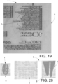
- One of the defects D in figure 18 is better visible in the enlargement of figure 19 .
- Figure 20 is a screenshot of the user interface 9, showing the comparison between image I of a group of flexographic plates and the respective reference images 8, where it is highlighted that the central plate of the group was mounted by mistake (and therefore does not correspond to the expected one, therefore there is no overlap between the two transparent images).
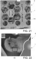
- Figure 21 is a screenshot of the user interface 9, showing the result of the acquisition of the image I of a printed film, performed by the scanning unit 7.
- Figure 22 is a screenshot of the machine's user interface 9, which represents a zoom, or enlargement, of the screenshot in Figure 21 , in particular at a first box R1.
- Figure 23 is a screenshot of the user interface 9, which represents a further zoom, or enlargement, of the screenshot in Figure 22 , in particular at a second box R2.
- machine 1 is able to highlight any defects even down to the printing grid level of a printed surface (for example a printed film, but not only).
- machine 1 is able to highlight, automatically and immediately, the defects D of a printing plate, or offset plate, or plate assembly, or printed surface 4, and in such a way as to allow the operator to evaluate the conformity, or otherwise, of the product.
- FIG. 11, 12 Another embodiment of the machine 1 according to the invention is illustrated in Figures 11, 12 .
- This embodiment of the machine 1 differs from that illustrated in the previous Figures 1-10 in that the scanning unit 7 includes at least one touch probe T.
- the touch probe T is configured to detect the physical characteristics of the printing plate, or offset plate, or plate assembly, or printed surface 4 to be evaluated, in order to obtain a three-dimensional scan.
- the touch probe T is operationally connected to the control unit 6, and thus also to the scanning sensor 16.
- the detections carried out by the touch probe T contribute, together with those of the scanning sensor 16, to reconstruct the real image of the printing plate, or offset plate, or plate assembly, or printed surface 4 to be evaluated, in three dimensions (therefore also considering the thickness of the object being evaluated).
- the touch probe T is associated with respective translation means 19, fixed to the carriage 10, which is able to translate the touch probe T in a direction perpendicular to the predetermined direction A; the touch probe T can thus reach all positions on the support plane 3.
- the touch probe T is particularly - but not exclusively - useful for detecting the wear of a printing plate, or offset plate, or plate assembly 4 (therefore detecting any discrepancies in thickness compared to the nominal one).
- the scan carried out with the aid of the touch probe T can, therefore, determine whether a certain printing plate, or offset plate, or plate assembly 4, used and therefore worn, is, or is not, within the acceptable dimensional tolerances for carrying out a certain job.
- the machine is an important tool for the operator in charge of printing, especially flexographic printing and not only, since it allows to automatically and preventively check - and therefore before any other operational or production phase - the quality of the printing plate, or offset plate, or plate assembly, or printed surface, so as to avoid, possibly, assembling of plates that are not compliant in terms of physical or surface characteristics and above all to avoid the creation of relative print tests or, even worse, to start or continue an incorrect printing job.
- the manufacturer thus avoids putting into circulation a product affected by manufacturing defects that could compromise the printing work.
Landscapes
- Engineering & Computer Science (AREA)
- Mechanical Engineering (AREA)
- Quality & Reliability (AREA)
- Inking, Control Or Cleaning Of Printing Machines (AREA)
- Investigating Materials By The Use Of Optical Means Adapted For Particular Applications (AREA)
Abstract
A machine (1) for checking flexographic printing plates, or offset plates, or plate assemblies, or printed surfaces, comprising a base (2), a support plane (3), associated with the base (2), for at least one printing plate, or offset plate, or plate assembly, or printed surface (4), the surface or physical characteristics of which are to be checked and controlled, a control unit (6), and a surface scanning unit (7) of the at least one printing plate, or offset plate, or plate assembly, or printed surface (4) to be checked. The scanning unit (7) is operatively connected to the control unit (6), and it is configured to acquire a real image (I) of the at least one printing plate, or offset plate, or plate assembly, or printed surface (4) to be checked. The control unit (6) is configured to automatically compare the real image (I) of at least one printing plate, or offset plate, or plate assembly, or printed surface (4), acquired by the scanning unit (7), and the reference image (8) corresponding to the creation file of a plate or a sheet of multiple plates or the creation file of the offset plate or the file of the final print to be produced, to automatically recognize any discrepancies or defects (D) in the analyzed material, in order to avoid the use of incorrect plates, avoid the creation of expensive print tests, automatically recognize and avoid an incorrect print or in order to speed up the initialization of new print jobs on existing machines without control systems, in any case reducing energy consumption and therefore CO2 in all these circumstances.
Description
- The present invention relates to a machine for checking flexographic plates, or of offset plates, or printing plates assemblies, or printed surfaces.
- More specifically, the present invention concerns a machine that allows for a preventive quality control of flexographic plates, or offset plates, or printing plates assemblies, or printed surfaces, so as to avoid the use of unsuitable plates and to avoid the creation of relative print tests or to speed up the initialization of new print jobs whilst, in all these circumstances, reducing energy consumption and therefore CO2.
- In various printing sectors, and in particular in the flexographic printing sector, with reference, by way of example only, to some application areas such as box factories and the like, but not only, before carrying out a specific printing job, it is necessary to carry out expensive and laborious printing tests with inks to verify the quality of the plate used, and/or its correct positioning on the printing cylinder.
- Such tests can be quite time-consuming, and of course the printing press cannot start operating profitably until the quality and/or positioning checks have given the expected results.
- The above tests can be carried out on specific dedicated machines, which have the function of allowing the execution of verification tests on the plates used in the printing job.
- By using such testing machines, we avoid having to carry out tests directly on the printing machine, which would be extremely expensive and laborious.
- The printing tests performed must then allow the operator to carry out a check, essentially of a visual nature, of the qualitative characteristics of the plate, in order to identify any defects or inaccuracies that could be the consequence of errors in the construction of the plate itself.
- To be effective, carrying out these visual checks naturally requires a certain amount of time, and also the skill of an expert operator.
- This verification time is inevitably added to the time needed to run the print tests on the dedicated machine.
- Furthermore, no matter how quickly these operations can be carried out, there remains a certain margin of uncertainty due to the human factor, namely the visual control carried out by the operator.
- Therefore, the need is felt to improve the state of the art in order to limit the time required for mounting unsuitable plates and the related printing tests, and also to be able to eliminate the uncertainties caused by possible errors committed by the operator in charge of quality checks.
- In fact, in cases where a plate is found to be affected by errors or inaccuracies, the economic damage for the user can be considerable, especially because a lot of time is wasted in returning the defective plate to the manufacturer, and in producing a replacement with the related new delivery.
- Similar considerations can be made for the field of offset printing, where the plates are absolutely not checked before use. This aspect can therefore lead to huge losses of material and money in the case of erroneous prints not previously checked.
- It should also be noted that there are numerous printing machines in operation on the market, including rotogravure, which do not have any in-line control system for the printed film.
- In order to initialize such printing machines, it is therefore necessary to consume several hundred meters before being able to verify with certainty the correctness of the printed material.
- It is therefore necessary to create an automated offline system that allows for the automatic verification and validation of such situations in order to avoid numerous wastes.
- The technical aim of the present invention is therefore to improve the state of the art in the printing sector, in particular - but not only - flexographic printing sector. Within such technical aim, it is an object of the present invention to develop a machine for checking flexographic printing plates, or offset plates, or printing plate assemblies, or printed surfaces, which allows the previously mentioned drawbacks to be overcome automatically and without human discretion.
- Another aim of the present invention is to make available a machine for checking flexographic printing plates, or offset plates, or printing plate assemblies, or printed surfaces, which allows qualitative checks to be carried out on a flexographic plate even when it has just been produced, and therefore upstream of any other test, or even on offset plates, or on plate assemblies, or on printed surfaces, just produced, or in order to speed up the initialization of new printing jobs on existing machines without control systems, in any case reducing energy consumption and therefore CO2 in all these circumstances.
- Another object of the present invention is to provide a machine for checking flexographic printing plates which allows the user to avoid the mounting of unsuitable plates and related printing tests to check the quality of a given plate.
- A further object of the present invention is to provide a machine for checking flexographic printing plates, or offset plates, or printing plate assemblies, or printed surfaces, which is constructionally simple and economical.
- Another object of the present invention is to devise a machine for checking flexographic printing plates, or offset plates, or printing plate assemblies, or printed surfaces, which is immediate, intuitive and versatile to use.
- This aim and these objects are all achieved by the machine for checking flexographic printing plates, or offset plates, or printing plate assemblies, or printed surfaces, according to the attached
claim 1. - The machine comprises a base, and a support plane, associated with the base, for at least one printing plate, or an offset plate, or a plate assembly, or a printed surface, the surface or physical characteristics of which must be automatically verified, validated and controlled.
- The machine also comprises a control unit, and a scanning unit for the surface of the at least one printing plate or an offset plate, or a plate assembly, or a printed surface, to be checked.
- The scanning unit is operationally connected to the control unit, and is configured to acquire a real image of the at least one printing plate, or the offset plate, or the plate assembly, or the printed surface, to be checked.
- The control unit is configured to perform a comparison between the real image of the at least one printing plate, or the offset plate, or the plate assembly, or the printed surface, acquired by the scanning unit, and the reference image corresponding to the plate creation file, or to the file of a sheet comprising multiple plates, or the offset plate creation file, or the file of the final print to be produced. The dependent claims refer to preferred and advantageous embodiments of the invention.
- According to another aspect of the invention, the scanning unit comprises a carriage, and guide means, provided in the base, for the aforementioned carriage; the carriage is slidable, above the support plane, along a predetermined direction.
- The scanning unit further comprises at least one scanning sensor installed on the carriage; the scanning sensor is fixed below the lower surface, in use, of the carriage, so as to be positioned facing the support plane, and at a given distance from the upper surface of the at least one printing plate, or offset plate, or plate assembly, or printed surface, to be checked.
- These and further advantages will be better understood by any person skilled in the art from the following description and the attached drawings, given as a nonlimiting example, in which:
-
Figure 1 is an axonometric view of the machine according to the invention; -
Figure 2 is a side view of the machine; -
Figure 3 is a front view of the machine; -
Figure 4 is a top view of the machine; -
Figure 5 is an isometric view of the machine with some parts removed; -
Figure 6 is an axonometric view of the machine with some parts removed, from a different angle; -
Figure 7 is a side view of the machine, with some parts removed; -
Figure 8 is a front view of the machine, with some parts removed; -
Figure 9 is a top view of the machine, with some parts removed; -
Figure 10 is a detail offigure 5 ; -
Figure 11 is a front view of the machine, according to another embodiment of the invention; -
Figure 12 is a top view of the machine according to the embodiment of -
Figure 11 ; -
Figure 13 is a screenshot of the machine's user interface, showing the result of the image acquisition of a flexographic plate, carried out by the scanning unit; -
Figure 14 is a screenshot of the machine's user interface, showing the comparison between the cliché image inFigure 13 and the respective reference image; -
Figure 15 is a screenshot of the machine's user interface, showing the automatic detection of defects that emerged from the comparison ofFigure 14 ; -
Figure 16 is a screenshot of the machine's user interface, showing the result of the image acquisition of another flexographic plate, performed by the scanning unit; -
Figure 17 is a screenshot of the machine's user interface, showing the comparison between the cliché image inFigure 16 and the respective reference image; -
Figure 18 is a screenshot of the machine's user interface, showing the automatic detection of defects that emerged from the comparison ofFigure 17 ; -
Figure 19 is an enlargement ofFigure 18 , corresponding to one of the defects detected; -
Figure 20 is a screenshot of the machine's user interface, showing the comparison between the image of a group of flexographic plates and their respective reference images, highlighting that the central plate of the group has been mounted by mistake; -
Figure 21 is a screenshot of the machine's user interface, showing the result of the image acquisition of a printed film, performed by the scanning unit; -
Figure 22 is a screen shot of the machine interface, which represents a zoom, or enlargement, of the screen inFigure 21 ; -
Figure 23 is a screen shot of the machine interface, which represents a zoom, or enlargement, of the screen inFigure 22 . - With reference to the attached figures, the
numeral 1 generally indicates a machine for checking flexographic printing plates, or offset plates, or printing plate assemblies, or printed surfaces, according to the present invention. - The
machine 1 comprises a base, indicated overall by 2. - The
machine 1 also includes asupport plane 3. - The
support plane 3 is associated with thebase 2, and it defines a support surface for at least one printing plate, or offset plate for offset printing, or plate mounting, or printedsurface 4, whose surface or physical characteristics must be verified and controlled. - In more detail - and with reference to the schematic representation in figure 1 - a single sheet 5 (typically made of photopolymer) can also be positioned on the
support plane 3, from whichdifferent plates 4 will then be obtained, by cutting, or different offset plates, or different plate assemblies, or different printed surfaces. In fact, infigure 1 , the dotted lines represent - schematically and only for better understanding - the cutting lines through which different plates 4 (or offset plates, or plate assemblies, or printed surfaces) will be obtained starting from thesingle sheet 5. - This allows for the optimization of the production phase of the plates 4 (or offset plates, or plate assemblies, or printed surfaces), exploiting, as much as possible, the entire surface of the
sheet 5, minimizing waste and scrap. - Alternatively, on the
support plane 3 it is also possible to place - obviously - one ormore plates 4, already made and finished (i.e., already cut), to be checked, or more offset plates, or more plate assemblies, or more printed surfaces. - It should be noted that the plates, or the
plate assemblies 4, can be either new or used (and therefore possibly superficially worn to a certain extent). - Furthermore, printed surfaces can also be made of printed films (transparent or non-transparent).
- The
machine 1 also comprises - and with particular reference to figure 3 - a control unit 6 (represented schematically);control unit 6 is configured to manage and supervise the operation ofmachine 1, as better described below. - According to one aspect of the invention, the
machine 1 also comprises a scanning unit, generally indicated by 7, of the surface of the at least one printing plate, or offset plate, or plate assembly, or printed surface, 4 to be checked. - The
scanning unit 7 is operatively connected to thecontrol unit 6, and it is configured to acquire a real image of the at least one printing plate, or offset plate, or plate assembly, or printed surface, 4 to be checked. - According to another aspect of the invention, the
control unit 6 is configured to carry out the comparison between the real image of the at least one printing plate, or offset plate, or plate assembly, or printedsurface 4, acquired by thescanning unit 7, and at least onecorresponding reference image 8, relating to the creation file of a plate 4 (or to the creation file of asheet 5 comprising several plates 4), or of an offset plate, or of the plate assembly, or of a printed surface, and the respective creation or printing file. - In more detail, the at least one
reference image 8 can be supplied as input to thecontrol unit 6 by the operator responsible for checking the at least oneprinting plate 4, or offset plate, or plate assembly, or printed surface. - In an embodiment of the invention of particular practical interest, the at least one
reference image 8 consists of a graphic file for the creation of aprinting plate 4, or of asheet 5 comprisingseveral plates 4, or, more generally, of a respective file for the creation or printing of the material to be produced. - The
machine 1 is also equipped with a user interface 9 (schematically represented in the aforementionedfigure 3 ), operationally connected to, and interlocked with, thecontrol unit 6, comprising at least one screen or monitor. - By means of the
aforementioned user interface 9, the operator in charge can set and insert the main parameters (for example, dimensional parameters) and instructions to carry out the verification of the characteristics of one ormore printing plates 4, or offset plates, or plate assemblies, or printed surfaces, to be verified. - By means of the aforementioned comparison, the
control unit 6 allows, automatically, to highlight (preferably, but not exclusively, on a screen of the user interface 9) any discrepancies (or defects D) between the real image I of the at least oneprinting plate 4, or offset plate, or plate assembly, or printed surface, and the at least onecorresponding reference image 8 of the creation file of aprinting plate 4, or of the creation file of asheet 5 comprisingseveral printing plates 4 or the respective creation or printing file of the material to be produced, so as to prevent, upstream of any other operational or production step, any errors or inaccuracies in the execution of the printing. - More specifically, through the aforementioned comparison, the operator is able to find out, very quickly and precisely, whether a certain cliché 4 (or each
cliché 4 positioned on the support plane 3), or offset plate, or cliché assembly, or printed surface, is suitable or not to carry out the printing job or jobs for which it was created, or whether it instead presents defects. - In other words, the operator, without any discretion of his own, and in an objective manner, is able to easily ascertain whether a certain printing plate 4 (or offset plate, or plate assembly) is affected by manufacturing defects of such a magnitude as to compromise the execution of the printing job, or jobs, for which it was created, or whether the printed surface is not compliant and presents defects.
- This saves the time needed to mount unsuitable plates, and avoids the physical production of expensive and laborious proofs, and of course prevents a print job from being started that will not produce the desired results, in the event that a particular plate 4 (or offset plate, or plate assembly) is not suitable for carrying it out.
- This also avoids having to ship the defective printing plate 4 (or offset plate, or plate assembly) to the user who requested it.
- The comparison between the at least one real image of the at least one
printing plate 4, or offset plate, or plate assembly, or printed surface, and the at least onecorresponding reference image 8, can be carried out in various ways. - Given that such a comparison could be carried out directly and visually by the operator, the invention nevertheless provides for the use of specific algorithms that allow for the automatic highlighting of the differences between the images, for an immediate comparison of the same, and therefore for an immediate and automatic identification of any manufacturing defects of the
printing plate 4, or offset plate, or plate assembly, or printed surface. - According to an aspect of the invention, the
user interface 9 is configured to show, superimposed in transparency (or with other more or less similar solutions), the real image I of the at least one printing plate, or offset plate, or plate assembly, or printedsurface 4, and therespective reference image 8; as better clarified below, any defects D are shown, or highlighted, by means of closed lines or circles that enclose the affected areas of the screen or with other similar solutions (for example, areas highlighted with different colors). - According to the invention, the
machine 1, in its different specially developed versions, can carry out, as mentioned, the verification of one or more printing plates, or offset plates, or plate assemblies, or printedsurfaces 4, arranged on theaforementioned support plane 3. - In this version of the
machine 1, the support plane 3 (and therefore the at least oneprinting plate 4, or offset plate, or plate assembly, or printed surface, to be checked) is fixed, while thescanning unit 7 moves with respect to it; in other versions of the invention, thescanning unit 7 could instead be kept fixed, while thesupport plane 3 is movable. - According to one aspect of the invention, the
support plane 3 for at least one printing plate, or offset plate, or plate assembly, or printed surface 4 (or for thephotopolymer sheet 5, from whichseveral plates 4 will be obtained) comprises at least one plate of transparent, or translucent, material, for reasons that will become clearer later. - For example, the
support plane 3 may comprise at least one glass plate, transparent or translucent. - According to another aspect of the invention, the
scanning unit 7 comprises acarriage 10, and guide means 11 for the saidcarriage 10; the guide means 11 are provided in thebase 2. - The
carriage 10 is movable, in a sliding manner, above thesupport plane 3, that is, in other words, it can translate with respect to the latter. - In more detail, the
carriage 10 is movable, above thesupport plane 3, along a predetermined direction A. - The
base 2 of themachine 1 has a roughly box-like shape; on its upper surface is installed thesupport plane 3 of the at least oneprinting plate 4, or offset plate, or plate assembly, or printed surface. - The
carriage 10 of thescanning unit 7, on the other hand, is substantially shaped like a portal, and is wider than thebase 2. - The guiding means 11 comprise, in more detail, first lateral guides 12, along which the
carriage 10 can slide. - The first lateral guides 12 are integral with the lateral sides of the
base 2 and, in more detail, extend along the external sides of theupper side members 13 of thebase 2; the first lateral guides 12 therefore define the sliding direction A of thecarriage 10. - The
carriage 10 can translate, along the guide means 11 (and therefore along the first lateral guides 12), manually, or, more preferably, automatically. - In this second case, the
scanning unit 7 comprises a drive unit, suitable for carrying out the translational movement of thecarriage 10 itself along the guide means 11. - The drive unit, housed inside the
carriage 10, may comprise at least one actuator; said actuator may be of any type suitable for carrying out such translational movement. - In the embodiment illustrated in the attached figures, the drive unit comprises, more specifically, two rotary actuators, for example two electric motors.
- The aforementioned actuators are installed at the two ends 14 of the
carriage 10. On the output axes of the above actuators respective toothed wheels (or pinions) are mounted, which engage tworespective racks 15, mounted on thebase 2 so as to be parallel to the lateral guides 12. - In more detail, as shown in the detail of
figure 10 , theracks 15 are mounted, parallel to the first lateral guides 12, along the external sides of theupper side members 13 of thebase 2. - Alternatively, the aforementioned drive unit may comprise a single electric motor, on which a first gear wheel is mounted, which engages a
first rack 15, placed on one side of thebase 2, and a transmission to transmit the motion to a second gear wheel, supported by thecarriage 10, which engages asecond rack 15, placed on the other side of thebase 2. - According to another aspect of the invention, the
scanning unit 7 comprises at least onescanning sensor 16. - In an embodiment of the invention of particular practical interest, and particularly advantageous, the
aforementioned scanning sensor 16 comprises at least one linear sensor, or other type of sensor. - The
scanning sensor 16 is installed on thecarriage 10. - The
aforementioned scanning sensor 16, through a relative motion with respect to the at least oneprinting plate 4, or offset plate, or plate assembly, or printed surface, (in particular through its translational motion with respect to theprinting plate 4, or offset plate, or plate assembly, or printed surface, which is instead kept fixed), and therefore through successive steps, provides for the acquisition of the complete real image of the same. - In the specific case in which a linear sensor, or another type of sensor or camera, is used, the latter produces an image consisting of a single line of pixels; the complete image is constructed by a processor (in this case, that of the control unit 6) by exploiting the relative motion between the linear camera itself and the surface of the object (printing plate, or offset plate, or plate assembly, or printed surface 4) of which the image is to be produced.
- In this embodiment, the
scanning sensor 16 is fixed below the lower surface, in use, of thecarriage 10. - In more detail, the
scanning sensor 16 is fixed below the lower surface, in use, of thecarriage 10 so as to be positioned facing thesupport plane 3, and at a certain distance (for example, a few millimeters) from the upper surface of the at least one printing plate, or offset plate, or plate assembly, or printedsurface 4 to be checked. Thescanning sensor 16 may be fixed beneath the lower surface, in use, of thecarriage 10 in an adjustable/registrable manner, to allow thescanning unit 7 to adapt toprinting plates 4, or offset plates, or plate assemblies, or printed surfaces of different thicknesses (for example, typically the thickness of the plates may vary between 1.14 mm to 5 mm). - The adjustment/registration of the
scanning sensor 16 with respect to thecarriage 10 can also be carried out manually, or in an automated manner, by means of a specifically designed linear actuator. - Both in the case in which the
carriage 10 can be moved along the lateral guides 12 manually, and in the case in which it can be moved automatically, thescanning unit 7 further comprises a sensor E, operationally connected to thescanning sensor 16 and to thecontrol unit 6, which detects the movement of thecarriage 10 along the lateral guides 12, thanks to the presence of a reference M along the aforementioned lateral guides 12; thecontrol unit 6, therefore, uses the information provided by the sensor E to construct the real image I of the at least one printing plate, or offset plate, or plate assembly, or printedsurface 4, synchronizing the images taken by thescanning sensor 16 with its movement detected, precisely, by the aforementioned sensor E. - According to another aspect of the invention, the
scanning unit 7 comprises alighting device 17 of the reading area of thescanning sensor 16. - In more detail, the
lighting device 17 comprises one or more first lighting bodies, positioned in proximity to the scanning sensor 16 (therefore mounted on the carriage 10). - For example, two first lighting bodies may be provided, positioned at the two long sides of the scanning sensor 16 (i.e., upstream and downstream of the
scanning sensor 16 with reference to the translation direction A of the carriage 10). Furthermore, the lighting device comprises at least a second lighting body 18 (represented, schematically, infigure 3 ), and translation means 19 of the aforementionedsecond lighting body 18 below thesupport plane 3. - The translation means 19 of the
second lighting body 18 are configured to advance thesecond lighting body 18 together with thecarriage 10, at the same speed. - The
second lighting body 18 can have a width (intended as the dimension perpendicular to the aforementioned translation direction A) such as to also illuminate the printing plates, or offset plates, or plate assemblies, or printedsurfaces 4, of larger dimensions (and therefore it can have a width substantially comparable to that of the support plane 3). - The
second lighting body 18 is associated with a respective support 20 (visible, for example, infigure 5 ). - With reference to
figures 5-10 , which show themachine 1 with some parts of thebase 2 removed for greater clarity, the translation means 19 of thesecond lighting body 18 include second lateral guides 21. - The second lateral guides 21 are fixed to the internal surfaces of the
upper side members 13 of thebase 2. - The
support 20 of thesecond lighting body 18 comprises, at the respective ends, sliding shoes along the aforementioned second lateral guides 21. - Furthermore, the translation means 19 of the
second lighting body 18 can be, for example, of the belt type. - In more detail, in the specific embodiment illustrated in the figures, the translation means 19 of the
second lighting body 18 comprise anelectric motor 22, on the output axis of which atoothed pulley 23 is mounted. - The
electric motor 22 is mounted on the front (or rear, depending on the chosen convention) face of thebase 2. - A
toothed belt 24, closed in a ring, is wound around thetoothed pulley 23 and afurther return pulley 25, supported on the rear (or front) face, in use; thesupport 20 of thesecond lighting body 18 is, in turn, fixed to the aforementionedtoothed belt 24. - Therefore, the operation of the
toothed belt 24 determines the advancement of thesupport 20 of thesecond lighting body 18 along the second lateral guides 21, and therefore along the predetermined sliding direction A. - Furthermore, other types of locking/constraint means may be provided for the at least one printing plate, or offset plate, or plate assembly, or printed
surface 4, on thesupport plane 3. - In an alternative embodiment of the
machine 1 according to the invention, thescanning unit 7 is fixed with respect to thebase 2, and thesupport plane 3 is slidable, with respect to thescanning unit 7, along a predetermined direction A. - In another alternative embodiment of the
machine 1 according to the invention, thescanning unit 7 is fixed with respect to thebase 2, and the at least one printing plate, or offset plate, or plate assembly, or printedsurface 4 is movable, with respect to thescanning unit 7, by means of a drive system (for example a conveyor belt, or the like). - The operation of the
machine 1 according to the invention is, in light of what has been described, completely intuitive. - Once the at least one printing plate, or offset plate, or plate assembly, or printed surface 4 (or more printing plates, or offset plates, or plate assembly, or printed surfaces 4) to be checked has been positioned (and possibly blocked) on the
support plane 3, themachine 1 is started, and then thescanning unit 7, and in particular thecarriage 10, starting from one end of thesupport plane 3 itself, is translated (manually, or, more preferably, automatically), along the first guide means 11, so as to progressively cover the entire surface of the at least one printing plate, or offset plate, or plate assembly, or printedsurface 4. - The
control unit 6 can thus progressively reconstruct the real image of the at least oneprinting plate 4 or offset plate, or plate assembly, or printed surface (or of the various printing plates, or offset plates, or plate assemblies, or printed surfaces 4). Once the acquisition is complete, thecarriage 10 stops at the other end of thesupport plane 3, and then returns to the starting position to begin another acquisition cycle. - At the same time as the
carriage 10 performs its translation and image acquisition stroke, the second illuminatingbody 18 is translated simultaneously with thecarriage 10, with the same advancement speed, so as to always be in the correct position with respect to the scanning sensor 16 (preferably, underneath it). - In fact, the transparent or
translucent support plane 3 allows the passage of light through the plate 5 (or at least one cliché, or offset plate, or cliché assembly, or printed surface 4), which is also made of an essentially transparent or translucent photopolymer, thus facilitating detection by thescanning sensor 16. - Even in the case of offset plates, or plate assemblies, or printed surfaces, the translucent material of the
support plane 3 helps and facilitates the reconstruction of the image. - Subsequently, the real image, acquired by the
scanning unit 7, of the at least one printing plate, or offset plate, or plate assembly, or printed surface 4 (or even of theentire sheet 5 comprising several plates 4) can be compared with thecorresponding reference image 8, previously supplied as input to the control unit 6 (for example in .pdf format), so as to highlight (also with the aid of special algorithms) any differences between the real image of the at least one printing plate, or offset plate, or plate assembly, or printedsurface 4, and theaforementioned reference image 8, which could potentially give rise to an incorrect printing job. -
Figures 13-20 show, for illustrative but not limiting purposes, some screenshots of theuser interface 9 of themachine 1 according to the invention, relating to some examples of verification, carried out by themachine 1 according to the invention, of flexographic plates, or groups of flexographic plates. - In more detail,
figure 13 is a screenshot of theuser interface 9, showing the result of the acquisition of image I of a given flexographic plate, carried out by thescanning unit 7. -
Figure 14 is a screenshot of theuser interface 9, showing the comparison between image I of the printing plate infigure 13 and therespective reference image 8, superimposed in transparency. -
Figure 15 is a screenshot of thesame user interface 9 of the machine, which shows the automatic detection of defects D that emerged from the comparison carried out by thecontrol unit 6. - Defects D are highlighted, for example, by closed lines, or circles or other similar solutions, which enclose the affected areas, in order to draw the operator's attention while validating, automatically or otherwise, the analyzed product.
-
Figure 16 is a screenshot of theuser interface 9, showing the result of the acquisition of image I of another flexographic plate, performed by thescanning unit 7. -
Figure 17 is a screenshot of theuser interface 9, showing the comparison between image I of the printing plate infigure 16 and therespective reference image 8, superimposed in transparency. -
Figure 18 is a screenshot of thesame user interface 9, showing the automatic detection of defects D that emerged from the comparison carried out by thecontrol unit 6. - Also in this case, it is noted that the defects D are highlighted by closed lines, or circles, which enclose the affected areas, in order to draw the operator's attention. One of the defects D in
figure 18 is better visible in the enlargement offigure 19 . -
Figure 20 is a screenshot of theuser interface 9, showing the comparison between image I of a group of flexographic plates and therespective reference images 8, where it is highlighted that the central plate of the group was mounted by mistake (and therefore does not correspond to the expected one, therefore there is no overlap between the two transparent images). -
Figure 21 is a screenshot of theuser interface 9, showing the result of the acquisition of the image I of a printed film, performed by thescanning unit 7. -
Figure 22 is a screenshot of the machine'suser interface 9, which represents a zoom, or enlargement, of the screenshot inFigure 21 , in particular at a first box R1. -
Figure 23 , on the other hand, is a screenshot of theuser interface 9, which represents a further zoom, or enlargement, of the screenshot inFigure 22 , in particular at a second box R2. - As can be seen in
Figure 23 ,machine 1 is able to highlight any defects even down to the printing grid level of a printed surface (for example a printed film, but not only). - As these examples clearly show, therefore,
machine 1 is able to highlight, automatically and immediately, the defects D of a printing plate, or offset plate, or plate assembly, or printedsurface 4, and in such a way as to allow the operator to evaluate the conformity, or otherwise, of the product. - Another embodiment of the
machine 1 according to the invention is illustrated inFigures 11, 12 . - This embodiment of the
machine 1 differs from that illustrated in the previousFigures 1-10 in that thescanning unit 7 includes at least one touch probe T. - The touch probe T is configured to detect the physical characteristics of the printing plate, or offset plate, or plate assembly, or printed
surface 4 to be evaluated, in order to obtain a three-dimensional scan. - The touch probe T is operationally connected to the
control unit 6, and thus also to thescanning sensor 16. - Thanks to this, the detections carried out by the touch probe T contribute, together with those of the
scanning sensor 16, to reconstruct the real image of the printing plate, or offset plate, or plate assembly, or printedsurface 4 to be evaluated, in three dimensions (therefore also considering the thickness of the object being evaluated). - The touch probe T is associated with respective translation means 19, fixed to the
carriage 10, which is able to translate the touch probe T in a direction perpendicular to the predetermined direction A; the touch probe T can thus reach all positions on thesupport plane 3. - The touch probe T is particularly - but not exclusively - useful for detecting the wear of a printing plate, or offset plate, or plate assembly 4 (therefore detecting any discrepancies in thickness compared to the nominal one).
- The scan carried out with the aid of the touch probe T can, therefore, determine whether a certain printing plate, or offset plate, or
plate assembly 4, used and therefore worn, is, or is not, within the acceptable dimensional tolerances for carrying out a certain job. - We have thus seen how the invention achieves the proposed aims.
- The machine is an important tool for the operator in charge of printing, especially flexographic printing and not only, since it allows to automatically and preventively check - and therefore before any other operational or production phase - the quality of the printing plate, or offset plate, or plate assembly, or printed surface, so as to avoid, possibly, assembling of plates that are not compliant in terms of physical or surface characteristics and above all to avoid the creation of relative print tests or, even worse, to start or continue an incorrect printing job.
- This result is obtained automatically, very quickly and extremely reliably, thus significantly limiting possible errors due to the human factor.
- The manufacturer thus avoids putting into circulation a product affected by manufacturing defects that could compromise the printing work.
- This saves significant economic, time and energy resources, reducing the energy consumption of printers.
- Considering that false starts in printing are estimated at 4-5% for each printer and that the invention can serve numerous printers, the energy savings and reduction of CO2 emissions are considerable, considering wasted energy, ink and material.
- The proposed construction solution is very simple, economical, and easy and intuitive to use.
- The present invention has been described according to preferred embodiments, but equivalent variants can be conceived without departing from the scope of protection offered by the following claims.
Claims (13)
- Machine (1) for checking flexographic printing plates, or offset plates, or plate assemblies, or printed surfaces, characterized in that it comprises a base (2),a support plane (3), associated with said base (2), for at least one printing plate (4), or offset plate, or plate assembly, or printed surface, the surface or physical characteristics of which are to be checked and controlled,a control unit (6),a surface scanning unit (7) of the at least one printing plate, or offset plate, or plate assembly, or printed surface (4) to be checked,said scanning unit (7) being operatively connected to said control unit (6), and configured to acquire a real image (I) of the at least one printing plate, or offset plate, or plate assembly, or printed surface (4) to be checked,said control unit (6) being configured to automatically compare said real image (I) of the at least one printing plate, or offset plate, or plate assembly, or printed surface (4), acquired by said scanning unit (7), and the reference image (8) corresponding to the creation file of a printing plate, or of a sheet of multiple plates, or the creation file of an offset plate or the file of the final print to be made, to automatically recognize any physical or superficial defects (D) in the analyzed object in order to validate it or not to avoid the use of incorrect or worn plates, or to avoid the creation of expensive print tests, or to automatically recognize and avoid an erroneous print or in order to speed up the initialization of new print jobs on existing machines without control systems, reducing in any case, in all these circumstances, energy consumption and therefore CO2.
- Machine (1) according to claim 1, wherein said scanning unit (7) comprises a carriage (10), and guide means (11), provided in said base (2), for said carriage (10), said carriage (10) being slidable, above said support plane (3), along a predetermined direction (A), or said scanning unit (7) is fixed with respect to said base (2), and said support plane (3) is slidable, with respect to said scanning unit (7), along a predetermined direction (A), or said scanning unit (7) is fixed with respect to said base (2), and said at least one printing plate, or offset plate, or plate assembly, or printed surface (4), is movable with respect to said scanning unit (7) by means of a drag system.
- Machine (1) according to claim 2, wherein said scanning unit (7) comprises at least one scanning sensor (16) installed on said carriage (10), said scanning sensor (16) being fixed below the lower surface, in use, of said carriage (10) so as to be positioned facing said support plane (3), and at a given distance from the upper surface of the at least one printing plate, or offset plate, or plate assembly, or printed surface (4) to be checked.
- Machine (1) according to claim 3, wherein said scanning sensor (16) comprises at least one linear sensor, or other type of sensor.
- Machine (1) according to claim 4, wherein said guide means (11) comprise first lateral guides (12) along which said carriage (10) moves, said first lateral guides (12) being integral with the lateral sides of said base (2), and defining said sliding direction (A) of said carriage (10).
- Machine (1) according to claim 5, wherein said scanning unit (7) comprises a drive unit suitable for carrying out the translation of said carriage (10) along said guide means (11), said drive unit comprising two rotary actuators, installed at the two ends (14) of said carriage (10), on whose output axes are mounted respective toothed wheels which engage two respective racks (15), mounted, on said base (2), parallel to said lateral guides (12).
- Machine (1) according to one of the preceding claims, wherein said support plane (3) for at least one printing plate, or offset plate, or plate assembly, or printed surface (4), comprises at least one sheet of transparent or translucent material.
- Machine (1) according to claim 7, wherein said scanning unit (7) comprises at least one lighting device (18) of the reading area of said scanning sensor (16).
- Machine (1) according to claim 8, wherein said lighting device (18) comprises at least one lighting body (18) and translation means (19) of said lighting body (18) underneath said support plane (3), said translation means (19) being configured to move said lighting body (18) forward together with said carriage (10), at the same speed.
- Machine (1) according to claim 5, wherein said scanning unit (7) comprises a sensor (E), operatively connected to said scanning sensor (16) and to said control unit (6), configured to detect the movement of said carriage (10) along said lateral guides (12), thanks to the presence of a reference (M) along said lateral guides (12), said control unit (6) being then configured to use the information provided by said sensor (E) to construct the real image (I) of the at least one printing plate, or offset plate, or plate assembly, or printed surface (4), by synchronizing the images taken by said scanning sensor (16) with its movement detected by said sensor (E).
- Machine (1) according to claim 3, wherein said scanning unit (7) comprises at least one touch probe (T), operatively connected to said control unit (6), configured to detect the physical characteristics of the printing plate, or offset plate, or plate assembly, or printed surface (4) to be evaluated, so as to obtain a three-dimensional scan thereof.
- Machine (1) according to claim 11, wherein said touch probe (T) is associated with respective translation means (19), fixed to said carriage (10), capable of translating said touch probe (T) in a direction perpendicular to said predetermined direction (A), so that said touch probe (T) can reach all positions on said support plane (3).
- Machine (1) according to claim 1, comprising a user interface (9) operationally connected to, and interlocked with, said control unit (6), comprising at least one screen or monitor, said user interface (9) being configured to show, superimposed in transparency, or with similar solutions, the real image (I) of the at least one printing plate, or offset plate, or plate assembly, or printed surface (4), and the respective reference image (8), in which any differences or defects (D) are automatically shown and highlighted by closed lines, or circles, which enclose the areas of the screen concerned or with other similar solutions, in order to validate the product or not.
Applications Claiming Priority (1)
| Application Number | Priority Date | Filing Date | Title |
|---|---|---|---|
| IT102023000022305A IT202300022305A1 (en) | 2023-10-24 | 2023-10-24 | FLEXOGRAPHIC PLATE CHECKING MACHINE |
Publications (1)
| Publication Number | Publication Date |
|---|---|
| EP4545304A1 true EP4545304A1 (en) | 2025-04-30 |
Family
ID=89897361
Family Applications (1)
| Application Number | Title | Priority Date | Filing Date |
|---|---|---|---|
| EP24208740.1A Pending EP4545304A1 (en) | 2023-10-24 | 2024-10-24 | Machine for checking flexographic plates, or offset plates, or plate assembly, or printed surfaces |
Country Status (2)
| Country | Link |
|---|---|
| EP (1) | EP4545304A1 (en) |
| IT (1) | IT202300022305A1 (en) |
Citations (5)
| Publication number | Priority date | Publication date | Assignee | Title |
|---|---|---|---|---|
| DE3234313A1 (en) * | 1981-09-16 | 1983-03-31 | Toshiba Kikai K.K., Tokyo | METHOD AND DEVICE FOR MEASURING THE PERCENTAGE OF THE GRID FOR PHOTOGRAPHIC FILMS |
| ITBO20090387A1 (en) * | 2009-06-16 | 2010-12-17 | Bieffebi Societa Per Azioni | APPARATUS FOR THE CONTROL OF GEOMETRIC PARAMETERS OF PRINTING GROUPS MADE OF FLEXOGRAPHIC CLICHES MOUNTED ON RESPECTIVE CYLINDERS, FLEXOGRAPHIC CLICHES MOUNTED ON THEIR RESPECTIVE SLEEVE PORTACLICHÉ AND CYLINDERS / SLEEVES INK DISTRIBUTORS |
| EP3251850A1 (en) * | 2016-06-01 | 2017-12-06 | Windmöller & Hölscher KG | Flexographic printing machine with mounter |
| CN112810298A (en) * | 2019-11-18 | 2021-05-18 | 博斯特比勒费尔德有限公司 | Method and test station for determining printing parameters of a printing press |
| EP3988313A1 (en) * | 2020-10-22 | 2022-04-27 | Heidelberger Druckmaschinen AG | Device for measuring elevations of the surface of a rotating body and system |
-
2023
- 2023-10-24 IT IT102023000022305A patent/IT202300022305A1/en unknown
-
2024
- 2024-10-24 EP EP24208740.1A patent/EP4545304A1/en active Pending
Patent Citations (5)
| Publication number | Priority date | Publication date | Assignee | Title |
|---|---|---|---|---|
| DE3234313A1 (en) * | 1981-09-16 | 1983-03-31 | Toshiba Kikai K.K., Tokyo | METHOD AND DEVICE FOR MEASURING THE PERCENTAGE OF THE GRID FOR PHOTOGRAPHIC FILMS |
| ITBO20090387A1 (en) * | 2009-06-16 | 2010-12-17 | Bieffebi Societa Per Azioni | APPARATUS FOR THE CONTROL OF GEOMETRIC PARAMETERS OF PRINTING GROUPS MADE OF FLEXOGRAPHIC CLICHES MOUNTED ON RESPECTIVE CYLINDERS, FLEXOGRAPHIC CLICHES MOUNTED ON THEIR RESPECTIVE SLEEVE PORTACLICHÉ AND CYLINDERS / SLEEVES INK DISTRIBUTORS |
| EP3251850A1 (en) * | 2016-06-01 | 2017-12-06 | Windmöller & Hölscher KG | Flexographic printing machine with mounter |
| CN112810298A (en) * | 2019-11-18 | 2021-05-18 | 博斯特比勒费尔德有限公司 | Method and test station for determining printing parameters of a printing press |
| EP3988313A1 (en) * | 2020-10-22 | 2022-04-27 | Heidelberger Druckmaschinen AG | Device for measuring elevations of the surface of a rotating body and system |
Also Published As
| Publication number | Publication date |
|---|---|
| IT202300022305A1 (en) | 2025-04-24 |
| US20250178335A1 (en) | 2025-06-05 |
Similar Documents
| Publication | Publication Date | Title |
|---|---|---|
| EP3199346B1 (en) | Device for offline inspection and color measurement of printed sheets for the production of banknotes and like printed securities | |
| CN1781704B (en) | Machine for mounting curved printing plates in mutual alignment with efficient data processing system | |
| US6026172A (en) | System and method for zoom lens calibration and method using same | |
| EP0636475B1 (en) | Automatic inspection of printing plates or cylinders | |
| JPH04223172A (en) | Printing package manufacture device and method and device for inspecting cutting quality | |
| EP3215367B1 (en) | Device and method for controlling direct printing machines | |
| EP1911588B2 (en) | Colour gauge head positioning device | |
| CN104520106B (en) | Method and apparatus for making galley be oriented on impression cylinder | |
| AU2013229059B2 (en) | Method of checking producibility of a composite security design of a security document on a line of production equipment and digital computer environment for implementing the same | |
| DE102015205238A1 (en) | SYSTEM FOR DETECTING UNINTERRUPTED INK JETS IN PRINT HEADS THAT EXPRESS CLEAR MATERIAL USING A LIGHT TRANSMITTER SUBSTRATE | |
| US20260138360A2 (en) | Machine for checking flexographic printing plates, or offset plates, or printing plates assemblies, or printed surfaces | |
| US20250178335A1 (en) | Machine for checking flexographic printing plates, or offset plates, or printing plates assemblies, or printed surfaces | |
| EP2974865B1 (en) | Method for the localization of a fault on a printing substrate and device for carrying out said method | |
| DE102007041673A1 (en) | Print image information producing method, involves converting sheet imaging data into portable data format and is compared with portable data format reference file and providing sheet imaging data with specific geometric resolution | |
| EP4385743A1 (en) | Method and device for synchronising a process for printing on cardboard | |
| US20140043643A1 (en) | Method and device for the control and management of the printing parameters of a printing machine, particularly with a plurality of consecutive printing processes | |
| JP2808234B2 (en) | Stamped character inspection system | |
| EP0909647A2 (en) | Control console for a printing machine | |
| EP1897690A1 (en) | Method of automatically adjusting the printing pressure in flexographic printers | |
| JP2019215348A (en) | Image inspection robot | |
| CN214472871U (en) | Table type motor vehicle number plate detection device | |
| JP5829933B2 (en) | Inspection device for display panel of vehicle instrument | |
| CN121424852A (en) | A control method and apparatus for an automated stamping device that can be cascaded and expanded. | |
| JPH03220556A (en) | Method and device for inspecting and correcting original pattern plate | |
| JPS6076347A (en) | Checkup procedure for printed matter and device therefor |
Legal Events
| Date | Code | Title | Description |
|---|---|---|---|
| PUAI | Public reference made under article 153(3) epc to a published international application that has entered the european phase |
Free format text: ORIGINAL CODE: 0009012 |
|
| STAA | Information on the status of an ep patent application or granted ep patent |
Free format text: STATUS: THE APPLICATION HAS BEEN PUBLISHED |
|
| AK | Designated contracting states |
Kind code of ref document: A1 Designated state(s): AL AT BE BG CH CY CZ DE DK EE ES FI FR GB GR HR HU IE IS IT LI LT LU LV MC ME MK MT NL NO PL PT RO RS SE SI SK SM TR |
|
| STAA | Information on the status of an ep patent application or granted ep patent |
Free format text: STATUS: REQUEST FOR EXAMINATION WAS MADE |
|
| 17P | Request for examination filed |
Effective date: 20251024 |