EP0909647A2 - Control console for a printing machine - Google Patents
Control console for a printing machine Download PDFInfo
- Publication number
- EP0909647A2 EP0909647A2 EP98115979A EP98115979A EP0909647A2 EP 0909647 A2 EP0909647 A2 EP 0909647A2 EP 98115979 A EP98115979 A EP 98115979A EP 98115979 A EP98115979 A EP 98115979A EP 0909647 A2 EP0909647 A2 EP 0909647A2
- Authority
- EP
- European Patent Office
- Prior art keywords
- printing
- control panel
- control
- panel according
- Prior art date
- Legal status (The legal status is an assumption and is not a legal conclusion. Google has not performed a legal analysis and makes no representation as to the accuracy of the status listed.)
- Granted
Links
Images
Classifications
-
- B—PERFORMING OPERATIONS; TRANSPORTING
- B41—PRINTING; LINING MACHINES; TYPEWRITERS; STAMPS
- B41F—PRINTING MACHINES OR PRESSES
- B41F33/00—Indicating, counting, warning, control or safety devices
Definitions
- the invention relates to a control panel for a printing press.
- Control and display elements to be structurally combined with the printing press.
- Printing presses with a substantial range of functions are usually one or provided several control desks.
- An easy-to-use control panel is table-shaped constructed, with input and display elements at working height.
- Storage areas can be provided and additional holders for a vertical arrangement of the Copies.
- the connection and power supply are in the form of inputs and outputs on the control panel provided by plugs, couplings and the like.
- At printers with one Printer control system are provided in the control panel computing means that can be connected to a computer network of the print shop.
- the object of the invention is to develop a control panel that takes up little space and low material and cost expenditure combines a multitude of functions, whereby the influence of external disturbing variables is reduced.
- the task is solved with a control panel that has the characteristics of Claim 1 has.
- the device for printing form production can be a device for in the control panel Production of a test print can be integrated.
- the computing means used for control can be connected to a network of a Printing company be connected, with circulation-related data on the customer, on Number of copies, the type of paper used and the completion date from a computer the production control can be transferred to a control computer in the control panel can. Likewise, data used to illustrate the printing forms and for Presetting of the printing press are required by a computer Prepress to be transferred.
- Aid facilities such as e.g. B. job bags, storage containers and data cartridges can be omitted.
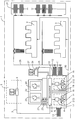
- FIG. 1 In the drawing is schematically a printing house 1 with two printing machines 2, 3, a control panel 4 and a prepress department 5 shown.
- a Layout computer 6 of the prepress department 5 is connected to a network 7 Control unit 8 connected.
- the control unit 8 contains at least hardware for one Computer, digital storage elements, a program system for realizing several Functions and interfaces or components for input and output of data or Signals.
- At the control panel 4 are an input point 9 and two output points 10, 11 for Pressure plates 12 are provided.
- the printing plates 12 for one print image each are located each in dustproof cassettes 13.
- a device 14 for printing form production and an image recording arrangement 15 installed.
- the Device 14 contains a processing table 16 for a printing plate 12, which in three Coordinate directions can be positioned. On one on the processing table 16 held printing plate 12, a laser 17 can be focused, with the energy in focus is sufficient to generate 12 pixels on the surface of the printing plates.
- the Image recording arrangement 15 contains a camera 18, with an imaged printing plate 12 using a measuring table 19 for scanning the camera 18 in at least two Directions can be positioned.
- control panel 4 for simultaneous imaging of multiple printing plates 12 multiple devices 14 for Printing form production can be provided. It is also possible within the Control panel 4, the device 14 for printing form production and Image recording arrangement 5 structurally to combine, so that the processing table 16th at the same time the measuring table 19.
- the handling of the pressure plate 12 within the Control panel 4 can be done so that the purpose of an entrance control not illustrated printing plate 12 of the image recording arrangement 15 is supplied, then the Device 14 for printing form production and then the image recording arrangement 14 is fed again for a final inspection.
- the one used for handling Conveying device can the pressure plates 12 in straight guides or on circular paths transport.
- Control elements 20 and display elements 21 are also provided on the control panel 4.
- a holder 22 for a test specimen 23 and for a OK copy 24 On a console 25 connected to the control panel 4 is a Computer 26 with a monitor 27.
- the control panel 4 is also available via a conveyor system 28 the printing presses 2, 3 and a storage system 29 in connection. Furthermore, that is Control panel 4 connected to printing presses 2, 3 via control lines 30.
- the control panel 4 serves to control at least one of the printing presses 2, 3 as well as the control of the methods for imaging the printing plate 12 and the Obtaining image signals with the aid of the image recording arrangement 15.
- the image data one generated on the layout computer 6 in the prepress department 5 Print images are transmitted to the computer of the control unit 8 via the network 7.
- Printing forms 12 can be preconditioned in the cassette 13. B. on brought to a certain temperature or in a certain humidity being held. While a printing plate 12 is being conveyed from the input point 9
- the processing table 16 can be followed by further processing steps for a Preparation for imaging is required. An example is cleaning and a coating of the printing plates 12 to be imaged.
- the illustration of the Printing plate 16 occurs pixel by pixel, with the processing table 16 positioning steps executes that perpendicular to the optical axis of the radiation emanating from the laser 17 lies.
- the pressure plate 12 can additionally in the direction of optical axis.
- the laser 17 is in accordance with the image data modulated.
- the image data originating from the computer 6 in the Control unit 8 to be processed for imaging data.
- pixels are generated on the surface of the printing plates. are ink-repellent.
- a printing plate 12 which is on the measuring table 19, with the help of the camera 18 the surface reproducing image data are obtained and fed to the control unit 8.
- the control unit 8 contains computing means for image analysis and pixel by pixel Target-actual comparison, which enables quality control of the imaging.
- the Image data of a set of printing plates 12 belonging to a print image can be the Computer 26 are supplied, the program for generating a print image contains the monitor 27.
- the operator of the printing press 2, 3 has the possibility visually check whether the printing plates 12 are correctly imaged.
- a can be sent to the control panel 4 Device for generating a test print connected or in the Control panel 4 can be integrated.
- the printing plates 12 belonging to a printed image are subjected to quality control stored in cassettes 13, which for further transport of the printing plates 12 to the Printing machines 2, 3 are docked at the issuing points 10, 11.
- a conveyor system 28 is provided for further transport.
- the cassettes 13 with the printing plates 12 are via guide rails depending on the scheduling to the printing units of the printing presses 2, 3 or promoted to the storage systems 29.
- an intermediate storage for printing plates 12 If a job is to be printed repeatedly, the sentence belonging to the job can be used can be fetched from the storage system 29 on pressure plates 12.
- the printing plates 12 for an order become an automatic system Plate feed to the respective printing unit of the printing presses 2, 3, where they are in the preparation phase for printing onto the respective printing form cylinders become.
- the image data from the computer 6 and the image data from the surface of the illustrated printing plates 12 are together with data on the printing presses 2, 3, on the substrate, the printing ink and other procedural variables for one Presetting of the printing presses 2, 3 and of the printing presses 2, 3 connected units used.
- the control of the printing presses 2, 3 takes place with the help of the control elements 20 and the display elements 21 from the control panel 4.
- a Part of the control elements 20 and the display elements 21 is provided Operations in imaging the printing plate 12 and in the extraction of it Control image data reproducing the printed image.
Landscapes
- Inking, Control Or Cleaning Of Printing Machines (AREA)
- Manufacture Or Reproduction Of Printing Formes (AREA)
- Exposure And Positioning Against Photoresist Photosensitive Materials (AREA)
Abstract
Description
Die Erfindung betrifft ein Steuerpult für eine Druckmaschine. Bei Druckmaschinen oder Druckvorrichtungen mit nur wenigen zu steuernden Betriebsvorgängen ist es bekannt, Bedien- und Anzeigeelemente mit der Druckmaschine baulich zu Vereinigen. Druckmaschinen mit einem erheblichen Funktionsumfang werden in der Regel ein oder mehrere Steuerpulte beigestellt. Ein bedienfreundliches Steuerpult ist tischförmig aufgebaut, wobei Eingabe- und Anzeigeelemente in Arbeitshöhe liegen. Zur Abmusterung von Druckexemplaren und zum Vergleich mit Vorlagen können auf dem Steuerpult Ablageflächen vorgesehen sein und zusätzlich Halter für eine vertikale Anordnung der Exemplare. Im Steuerpult selbst sind Stromversorgungen, signalverarbeitende Elemente und Stellelemente im wesentlichen berührungssicher untergebracht. Zur signaltechnischen Verbindung und zur Energieversorgung sind am Steuerpult Ein- und Ausgänge in Form von Steckern, Kupplungen und dergleichen vorgesehen. Bei Druckereien mit einem Druckerei-Steuerungssystem sind im Steuerpult rechentechnische Mittel vorgesehen, die mit einem Rechner-Netzwerk der Druckerei verbunden sein können.The invention relates to a control panel for a printing press. For printing machines or Printing devices with only a few operations to be controlled, it is known Control and display elements to be structurally combined with the printing press. Printing presses with a substantial range of functions are usually one or provided several control desks. An easy-to-use control panel is table-shaped constructed, with input and display elements at working height. For sampling of printed copies and for comparison with templates can be made on the control panel Storage areas can be provided and additional holders for a vertical arrangement of the Copies. In the control panel itself there are power supplies, signal processing elements and control elements housed essentially touch-safe. For signaling The connection and power supply are in the form of inputs and outputs on the control panel provided by plugs, couplings and the like. At printers with one Printer control system are provided in the control panel computing means that can be connected to a computer network of the print shop.
Es sind weiterhin Steuerpulte bekannt, die Ablagen für bebilderte Druckplatten oder Druckexemplare, für Werkzeuge, Meßmittel und Hilfsstoffe aufweisen.There are also control desks known, the shelves for illustrated printing plates or Print copies, for tools, measuring equipment and auxiliary materials.
Aus Platzgründen und aus herstellungsbedingten Gründen sind Einrichtungen, die nicht primär zur Steuerung oder Regelung von Betriebsvorgängen dienen, in separaten Gehäusen untergebracht. Als Beispiele seien Registerstanzen, Vorrichtungen zur Herstellung von Druckformen und Drückplattenleser genannt. Zur Vereinfachung der Druckvorbereitung einer Druckform ist in der DE 43 06 677 C2 eine Lösung beschrieben, bei der eine Registerstanze und ein Plattenleser in einem Gerät untergebracht sind.For space and manufacturing reasons, facilities are not serve primarily to control or regulate operating processes, in separate Housings housed. Examples are register punches, devices for Manufacture of printing forms and pressure plate readers. To simplify the Preparation of a printing form for printing is described in DE 43 06 677 C2, in which a register punch and a plate reader are accommodated in one device.
Bei zusammengestellten Geräten verschiedener Hersteller ist die Bedienung in den meisten Fällen nicht einheitlich und es besteht häufig keine Kompatibilität der Steuerungsdaten. Zudem benötigen mehrere einzeln aufgestellte Komponenten mehr Material und eine größere Aufstellfläche. Der Transport von Daten und Material zwischen den Komponenten gestaltet sich schwierig und störanfällig.When devices from different manufacturers are put together, the operation is in the in most cases not uniform and there is often no compatibility of the Control data. In addition, several individually installed components require more Material and a larger footprint. The transport of data and material between the components are difficult and prone to failure.
Aufgabe der Erfindung ist es, ein Steuerpult zu entwickeln, das bei geringem Platzbedarf und geringem Material- und Kostenaufwand eine Vielzahl von Funktionen in sich vereint, wobei der Einfluß von außen angreifender Störgrößen verringert ist.The object of the invention is to develop a control panel that takes up little space and low material and cost expenditure combines a multitude of functions, whereby the influence of external disturbing variables is reduced.
Die Lösung der Aufgabe gelingt mit einem Steuerpult, das die Merkmale des
Anspruches 1 aufweist.The task is solved with a control panel that has the characteristics of
Dadurch, daß in das Steuerpult mindestens eine Einrichtung zur Druckform-Herstellung integriert ist, entstehen eine Reihe von Vorteilen: Durch Vermeidung einer separat aufgestellten Einrichtung zur Druckform-Herstellung wird weniger Aufstellfläche und weniger umbautes Volumen benötigt. Energieversorgungseinrichtungen und rechentechnische Mittel müssen nicht mehrfach vorgesehen werden. Die Bedien- und Anzeigeelemente des Steuerpultes dienen sowohl der Steuerung der Druckmaschine als auch der Steuerung der Betriebsvorgänge bei der Herstellung der Druckform. Die Bedienung aller Komponenten vereinfacht sich, weil die Bedienoberfläche für alle Bedienelemente vereinheitlicht ist. Die Kontrolle der Druckform-Herstellung und der Druckmaschine selbst läßt sich mit einem ganzheitlichen Datenkonzept realisieren. Neben der Einrichtung zur Druckform-Herstellung kann in das Steuerpult eine Vorrichtung zur Herstellung eines Probedruckes integriert sein. Characterized in that at least one device for printing form production in the control panel Integrated, there are a number of advantages: By avoiding a separate erected device for printing form production is less footprint and less volume is needed. Energy supply facilities and computing means need not be provided multiple times. The operating and Display elements of the control panel serve both to control the printing press and also the control of the operations in the production of the printing form. The Operation of all components is simplified because the user interface for everyone Controls is unified. The control of the printing form production and the Printing machine itself can be realized with a holistic data concept. Next the device for printing form production can be a device for in the control panel Production of a test print can be integrated.
Die zur Steuerung dienenden rechentechnischen Mittel können an ein Netzwerk einer Druckerei angebunden sein, wobei auflagenbezogene Daten zum Kunden, zur Auflagenzahl, zur verwendeten Papiersorte und zum Fertigstelltermin von einem Rechner der Produktions-Steuerung auf einen Steuerrechner im Steuerpult übertragen werden können. Ebenso können Daten, die zur Bebilderung der Druckformen und zur Voreinstellung der Druckmaschine benötigt werden, von einem Rechner der Druckvorstufe übertragen werden.The computing means used for control can be connected to a network of a Printing company be connected, with circulation-related data on the customer, on Number of copies, the type of paper used and the completion date from a computer the production control can be transferred to a control computer in the control panel can. Likewise, data used to illustrate the printing forms and for Presetting of the printing press are required by a computer Prepress to be transferred.
Die Handhabung der Druckformen wird weniger störanfällig. Hilfseinrichtungen, wie z. B. Auftragstaschen, Ablagebehälter und Datenkassetten, können entfallen.The handling of the printing forms is less prone to failure. Aid facilities such as e.g. B. job bags, storage containers and data cartridges can be omitted.
Die Erfindung soll nachstehend anhand eines Ausführungsbeispieles näher erläutert
werden: In der Zeichnung ist schematisch eine Druckerei 1 mit zwei Druckmaschinen
2, 3, einem Steuerpult 4 und einer Druck-Vorstufenabteilung 5 dargestellt. Ein
Layout-Rechner 6 der Druck-Vorstufenabteilung 5 ist über ein Netzwerk 7 mit einer
Steuereinheit 8 verbunden. Die Steuereinheit 8 enthält mindestens Hardware für einen
Rechner, digitale Speicherelemente, ein Programmsystem zur Realisierung mehrerer
Funktionen und Schnittstellen bzw. Bauelemente zur Ein.- und Ausgabe von Daten bzw.
Signalen. Am Steuerpult 4 sind eine Eingabestelle 9 und zwei Ausgabestellen 10, 11 für
Druckplatten 12 vorgesehen. Die Druckplatten 12 für je ein Druckbild befinden sich
jeweils in staubdichten Kassetten 13. Innerhalb des Steuerpultes 4 sind eine Einrichtung
14 zur Druckformherstellung und eine Bildaufnahmeanordnung 15 installiert. Die
Einrichtung 14 enthält einen Bearbeitungstisch 16 für eine Druckplatte 12, der in drei
Koordinatenrichtungen positionierbar ist. Aufeine auf dem Bearbeitungstisch 16
gehaltene Druckplatte 12 ist ein Laser 17 fokussierbar, wobei die Energie im Fokus
ausreichend ist, um auf der Oberfläche der Druckplatten 12 Bildpunkte zu erzeugen. Die
Bildaufnahmeanordnung 15 enthält eine Kamera 18, wobei eine bebilderte Druckplatte 12
mit Hilfe eines Meßtisches 19 zum Abtasten bezuglich der Kamera 18 in mindestens zwei
Richtungen positionierbar ist.The invention will be explained in more detail below using an exemplary embodiment
are: In the drawing is schematically a
In einer nicht weiter dargestellten Variante können innerhalb des Steuerpultes 4 zur
simultanen Bebilderung mehrerer Druckplatten 12 mehrere Einrichtungen 14 zur
Druckform-Herstellung vorgesehen sein. Ebenso ist es möglich, innerhalb des
Steuerpultes 4 die Einrichtung 14 zur Druckform-Herstellung und die
Bildaufnahmeanordnung 5 baulich zu vereinigen, so daß der Bearbeitungstisch 16
gleichzeitig der Meßtisch 19 ist. Die Handhabung der Druckplatte 12 innerhalb des
Steuerpultes 4 kann so geschehen, daß zwecks einer Eingangskontrolle die nicht
bebilderte Druckplatte 12 der Bildaufnahmeanordnung 15 zugeführt wird, danach der
Einrichtung 14 zur Druckform-Herstellung und danach der Bildaufnahmeanordnung 14
zwecks einer Endkontrolle erneut zugeführt wird. Die zur Handhabung dienende
Fördereinrichtung kann die Druckplatten 12 in Geradführungen oder auf Kreisbahnen
transportieren.In a variant not shown, within the control panel 4 for
simultaneous imaging of
Am Steuerpult 4 sind weiterhin Bedienelemente 20 und Anzeigeelemente 21 vorgesehen.
Am Steuerpult 4 befindet sich ein Halter 22 für ein Testexemplar 23 und für ein
OK-Exemplar 24. Auf einer mit dem Steuerpult 4 verbundenen Konsole 25 steht ein
Rechner 26 mit einem Monitor 27. Das Steuerpult 4 steht über ein Fördersystem 28 mit
den Druckmaschinen 2, 3 und einem Lagersystem 29 in Verbindung. Weiterhin ist das
Steuerpult 4 über Steuerleitungen 30 mit den Druckmaschinen 2, 3 verbunden.
Das Steuerpult 4 dient sowohl der Steuerung mindestens einer der Druckmaschinen 2, 3
als auch der Steuerung der Verfahren zur Bebilderung der Druckplatte 12 und der
Gewinnung von Bildsignalen mit Hilfe der Bildaufnahmeanordnung 15. Die Bilddaten
eines auf dem Layout-Rechner 6 in der Druckvorstufenabteilung 5 generierten
Druckbildes werden über das Netzwerk 7 zu dem Rechner der Steuereinheit 8 übertragen. The control panel 4 serves to control at least one of the printing presses 2, 3
as well as the control of the methods for imaging the
In der Kassette 13 an der Eingabestelle 9 befinden sich unbebilderte Druckformen 12. Die
Druckformen 12 können in der Kassette 13 vorkonditioniert werden, wozu sie z. B. auf
eine bestimmte Temperatur gebracht werden oder in einer bestimmten Luftfeuchtigkeit
gehalten werden. Während des Förderns einer Druckplatte 12 von der Eingabestelle 9 auf
den Bearbeitungstisch 16 können weitere Bearbeitungsschritte folgen, die für eine
Vorbereitung zur Bebilderung erforderlich sind. Als Beispiel seien eine Reinigung und
eine Beschichtung der zu bebildernden Druckplatten 12 genannt. Die Bebilderung der
Druckplatte 16 geschieht pixelweise, wobei der Bearbeitungstisch 16 Positionierschritte
ausführt, die senkrecht zur optischen Achse der vom Laser 17 ausgehenden Strahlung
liegt. Zur Fokussierung der Strahlung kann die Druckplatte 12 zusätzlich in Richtung der
optischen Achse positioniert werden. Der Laser 17 wird entsprechend den Bilddaten
moduliert. Hierzu können die vom Rechner 6 stammenden Bilddaten in der
Steuereinheit 8 zu Bebilderungsdaten verarbeitet werden. Durch die Bebilderung werden
auf der Oberfläche der Druckplatten 12 Bildpunkte erzeugt, die farbannehmend bzw.
farbabstoßend sind. Gleichzeitig mit der Bebilderung können von einer Druckplatte 12,
die sich auf dem Meßtisch 19 befindet, mit Hilfe der Kamera 18 die Oberfläche
wiedergebende Bilddaten gewonnen werden und der Steuereinheit 8 zugeführt werden.
Die Steuereinheit 8 enthält rechentechnische Mittel zur Bildanalyse und zum pixelweisen
Soll-Ist-Vergleich, wodurch eine Qualitätskontrolle der Bebilderung möglich ist. Die
Bilddaten eines zu einem Druckbild gehörenden Satzes von Druckplatten 12 können dem
Rechner 26 zugeführt werden, der ein Programm zum Generieren eines Druckbildes auf
dem Monitor 27 enthält. Der Bediener der Druckmaschine 2, 3 hat so die Möglichkeit
visuell zu überprüfen, ob die Druckplatten 12 richtig bebildert sind.There are
Zusätzlich zu der Erzeugung eines sogenannten Softproofes kann an das Steuerpult 4 eine Einrichtung zum Erzeugen eines Probedruckes angeschlossen sein oder in das Steuerpult 4 integriert sein. In addition to the generation of a so-called soft proof, a can be sent to the control panel 4 Device for generating a test print connected or in the Control panel 4 can be integrated.
Die zu einem Druckbild gehörenden Druckplatten 12 werden nach der Qualitätskontrolle
in Kassetten 13 abgelegt, die zum Weitertransport der Druckplatten 12 zu den
Druckmaschinen 2, 3 an den Ausgabestellen 10, 11 angedockt sind. Zum Weitertransport
ist ein Fördersystem 28 vorgesehen. Die Kassetten 13 mit den Druckplatten 12 werden
über Führungsschienen je nach Disponierung zu den Druckwerken der Druckmaschinen
2, 3 oder zu den Lagersystemen 29 gefördert. Für die nacheinander abzuarbeitenden
Aufträge kann im Steuerpult 4 ein Zwischenlager für Druckplatten 12 vorgesehen sein.
Soll ein Auftrag wiederholt gedruckt werden, dann kann der zum Auftrag gehörende Satz
an Druckplatten 12 aus dem Lagersystem 29 geholt werden.The
Die Druckplatten 12 für einen Auftrag werden einem System zum automatischen
Platteneinzug dem jeweiligen Druckwerk der Druckmaschinen 2, 3 zugeführt, wo sie in
der Vorbereitungsphase zum Drucken auf die jeweiligen Druckformzylinder aufgespannt
werden. Die Bilddaten aus dem Rechner 6 und die Bilddaten von der Oberfläche der
bebilderten Druckplatten 12 werden gemeinsam mit Daten zu den Druckmaschinen 2, 3,
zum Bedruckstoff, zur Druckfarbe und zu weiteren verfahrenstechnischen Größen für eine
Voreinstellung der Druckmaschinen 2, 3 und der an die Druckmaschinen 2, 3
angeschlossenen Aggregate verwendet. Die Steuerung der Druckmaschinen 2, 3 erfolgt
mit Hilfe der Bedienelemente 20 und der Anzeigeelemente 21 vom Steuerpult 4 aus. Ein
Teil der Bedienelemente 20 und der Anzeigeelemente 21 ist dazu vorgesehen,
Betriebsvorgänge bei der Bebilderung der Druckplatte 12 und bei der Gewinnung von das
Druckbild wiedergebenden Bilddaten zu steuern. The
- 11
- Druckereiprinting house
- 2, 32, 3
- DruckmaschinePrinting press
- 44th
- SteuerpultControl panel
- 55
- DruckvorstufenabteilungPrepress department
- 66
- Layout-RechnerLayout calculator
- 77
- Netzwerknetwork
- 88th
- SteuereinheitControl unit
- 99
- EingabestelleEntry point
- 10,1110.11
- AusgabestelleIssuing office
- 1212th
- DruckplattenPrinting plates
- 1313
- KassettenCassettes
- 1414
- EinrichtungFacility
- 1515
- BildaufnahmeanordnungImage acquisition arrangement
- 1616
- BearbeitungstischMachining table
- 1717th
- Laserlaser
- 1818th
- Kameracamera
- 1919th
- MeßtischMeasuring table
- 2020th
- BedienelementeControls
- 2121
- AnzeigeelementDisplay element
- 2222
- Halterholder
- 2323
- TestexemplarTest copy
- 2424th
- OK-ExemplarOK copy
- 2525th
- Konsoleconsole
- 2626
- Rechnercomputer
- 2727
- Monitor monitor
- 2828
- FördersystemConveyor system
- 2929
- LagersystemStorage system
- 3030th
- SteuerleitungenControl lines
Claims (7)
mit Bedien- und Anzeigeelementen für die Steuerung von Betriebsvorgängen der Druckmaschine,
dadurch gekennzeichnet,
daß eine Einrichtung zur Druckform-Herstellung (14) integriert ist.Control panel for a printing press,
with operating and display elements for the control of operations of the printing press,
characterized,
that a device for printing form production (14) is integrated.
dadurch gekennzeichnet,
daß eine Eingabestelle für unbebilderte Druckformen (12) vorgesehen ist, daß eine Anordnung zur Bebilderung der Druckformen (12) vorgesehen ist, und daß mindestens eine Vorrichtung zum Speichern (8) von zu einem Druckbild gehörenden bebilderten Druckformen (12) vorgesehen ist.Control panel according to claim 1,
characterized,
that an input point for unimaged printing forms (12) is provided, that an arrangement for imaging the printing forms (12) is provided, and that at least one device is provided for storing (8) of illustrated printing forms (12) belonging to a print image.
dadurch gekennzeichnet
daß die Einrichtung (14) zur Druckform-Herstellung mit einer Vorrichtung (28) zum Fördern der bebilderten Druckformen (12) zur Druckmaschine (2, 3) gekoppelt ist.Control panel according to claim 2,
characterized
that the device (14) for printing form production is coupled to a device (28) for conveying the illustrated printing forms (12) to the printing press (2, 3).
dadurch gekennzeichnet,
daß der Anordnung (14) zur Bebilderung eine Qualitätskontrollvorrichtung für die bebilderten Druckformen (12) zugeordnet ist. Control panel according to claim 2,
characterized,
that the arrangement (14) for imaging is associated with a quality control device for the illustrated printing forms (12).
dadurch gekennzeichnet,
daß zum Visualisieren der Bebilderung dem Steuerpult (4) ein Farbbildschirm (27) zugeordnet ist.Control panel according to claim 4,
characterized,
that a color screen (27) is assigned to the control panel (4) for visualizing the illustration.
dadurch gekennzeichnet,
daß zusätzlich eine Einrichtung zum Erzeugen eines Probedruckes integriert ist.Control panel according to claim 1,
characterized,
that an additional device for generating a test print is integrated.
dadurch gekennzeichnet,
daß die das Druckbild wiedergebenden Bilddaten über den Bus eines mit der Einrichtung (14) zur Druckform-Herstellung in Verbindung stehenden Rechner-Netzwerkes (7) abrufbar sind.Control panel according to claim 1,
characterized,
that the image data reproducing the print image can be called up via the bus of a computer network (7) connected to the device (14) for printing form production.
Applications Claiming Priority (2)
| Application Number | Priority Date | Filing Date | Title |
|---|---|---|---|
| DE19743819 | 1997-10-05 | ||
| DE19743819A DE19743819A1 (en) | 1997-10-05 | 1997-10-05 | Control panel for a printing press |
Publications (3)
| Publication Number | Publication Date |
|---|---|
| EP0909647A2 true EP0909647A2 (en) | 1999-04-21 |
| EP0909647A3 EP0909647A3 (en) | 1999-09-29 |
| EP0909647B1 EP0909647B1 (en) | 2003-02-12 |
Family
ID=7844546
Family Applications (1)
| Application Number | Title | Priority Date | Filing Date |
|---|---|---|---|
| EP98115979A Expired - Lifetime EP0909647B1 (en) | 1997-10-05 | 1998-08-25 | Control console for a printing machine |
Country Status (4)
| Country | Link |
|---|---|
| US (1) | US6161480A (en) |
| EP (1) | EP0909647B1 (en) |
| JP (1) | JPH11192686A (en) |
| DE (2) | DE19743819A1 (en) |
Families Citing this family (7)
| Publication number | Priority date | Publication date | Assignee | Title |
|---|---|---|---|---|
| DE19961605A1 (en) * | 1999-01-18 | 2000-07-20 | Heidelberger Druckmasch Ag | Printing press for multiple color printing has image transfer process which prepares print masters for subsequent application to transfer rollers while previous images are being printed |
| JP3472541B2 (en) * | 2000-09-14 | 2003-12-02 | 株式会社東京機械製作所 | Printing material lifting device |
| FR2818191B1 (en) * | 2000-12-14 | 2003-08-15 | Jean Lucien Sarda | METHOD FOR DEINKING, CLEANING AND MAINTENANCE OF PRINTING PRESSES AND DEVICE FOR CARRYING OUT THIS METHOD |
| US6633821B2 (en) * | 2001-01-08 | 2003-10-14 | Xerox Corporation | System for sensing factory workspace |
| DE10163418B4 (en) * | 2001-05-03 | 2012-03-08 | Heidelberger Druckmaschinen Ag | Process for sequence control in a printing production plant |
| US6722279B2 (en) * | 2001-12-05 | 2004-04-20 | Heidelberger Druckmaschinen Ag | Device and corresponding method for rapid image data transfer in printing presses |
| EP1829356A1 (en) * | 2004-12-20 | 2007-09-05 | Koenig & Bauer AG | Communications system with a network for transmitting image data to at least one illustrating device and communications system with a network for controlling and/or monitoring a printing machine having a number of sections |
Citations (5)
| Publication number | Priority date | Publication date | Assignee | Title |
|---|---|---|---|---|
| EP0243661A1 (en) * | 1986-04-30 | 1987-11-04 | Heidelberger Druckmaschinen Aktiengesellschaft | Printing machine with at least one printing unit |
| DE3835107A1 (en) * | 1987-10-14 | 1989-04-27 | Ricoh Kk | OFFSET PRINTER |
| DE3908270A1 (en) * | 1988-03-15 | 1989-09-28 | Dainippon Printing Co Ltd | DEVICE AND PRINTING SYSTEM FOR DEVELOPING A LITHOGRAPHIC PLATE FOR PRINTING AND MEASURING ITS IMAGE SIZE |
| DE4041430A1 (en) * | 1989-12-22 | 1991-07-04 | Ricoh Kk | CONTROL DEVICE FOR A MATRIX COPIER |
| DE19506425A1 (en) * | 1995-02-24 | 1996-08-29 | Heidelberger Druckmasch Ag | Offset printing useful esp. for ink amt. adjustment and control |
Family Cites Families (10)
| Publication number | Priority date | Publication date | Assignee | Title |
|---|---|---|---|---|
| US3781109A (en) * | 1970-12-31 | 1973-12-25 | Coded Signatures Inc | Data encoding and decoding apparatus and method |
| DE2430762A1 (en) * | 1974-06-26 | 1976-01-15 | Gruner & Jahr | PROCESS FOR INFORMATION PROCESSING FOR THE PRODUCTION OF A PRINTING FORM AND DEVICE FOR CARRYING OUT THE PROCESS |
| US4495582A (en) * | 1982-06-04 | 1985-01-22 | Harris Graphics Corporation | Control system for pre-setting and operation of a printing press and collator |
| JPS6262762A (en) * | 1985-09-12 | 1987-03-19 | Tokyo Kikai Seisakusho:Kk | Production step managing system for newspaper printing |
| JPH0764525A (en) * | 1990-02-05 | 1995-03-10 | Scitex Corp Ltd | Apparatus and method for processing of color image |
| DE4306677C2 (en) * | 1993-03-04 | 1995-01-19 | Heidelberger Druckmasch Ag | Device for printing preparation with a printing form of a printing press |
| US5528377A (en) * | 1994-03-29 | 1996-06-18 | E. I. Du Pont De Nemours And Company | Extended density color printing |
| JP2962686B2 (en) * | 1997-02-07 | 1999-10-12 | 株式会社金田機械製作所 | Plate making equipment for newspaper printing |
| DE69810733T2 (en) * | 1997-10-24 | 2003-07-10 | Fuji Photo Film Co., Ltd. | Apparatus for making a printing plate and printer and printing system using this device |
| JP3007077B1 (en) * | 1998-09-09 | 2000-02-07 | 株式会社金田機械製作所 | Plate making equipment for newspaper printing |
-
1997
- 1997-10-05 DE DE19743819A patent/DE19743819A1/en not_active Withdrawn
-
1998
- 1998-08-25 EP EP98115979A patent/EP0909647B1/en not_active Expired - Lifetime
- 1998-08-25 DE DE59807171T patent/DE59807171D1/en not_active Expired - Fee Related
- 1998-10-02 US US09/165,874 patent/US6161480A/en not_active Expired - Fee Related
- 1998-10-05 JP JP10282585A patent/JPH11192686A/en active Pending
Patent Citations (5)
| Publication number | Priority date | Publication date | Assignee | Title |
|---|---|---|---|---|
| EP0243661A1 (en) * | 1986-04-30 | 1987-11-04 | Heidelberger Druckmaschinen Aktiengesellschaft | Printing machine with at least one printing unit |
| DE3835107A1 (en) * | 1987-10-14 | 1989-04-27 | Ricoh Kk | OFFSET PRINTER |
| DE3908270A1 (en) * | 1988-03-15 | 1989-09-28 | Dainippon Printing Co Ltd | DEVICE AND PRINTING SYSTEM FOR DEVELOPING A LITHOGRAPHIC PLATE FOR PRINTING AND MEASURING ITS IMAGE SIZE |
| DE4041430A1 (en) * | 1989-12-22 | 1991-07-04 | Ricoh Kk | CONTROL DEVICE FOR A MATRIX COPIER |
| DE19506425A1 (en) * | 1995-02-24 | 1996-08-29 | Heidelberger Druckmasch Ag | Offset printing useful esp. for ink amt. adjustment and control |
Also Published As
| Publication number | Publication date |
|---|---|
| EP0909647A3 (en) | 1999-09-29 |
| EP0909647B1 (en) | 2003-02-12 |
| US6161480A (en) | 2000-12-19 |
| JPH11192686A (en) | 1999-07-21 |
| DE19743819A1 (en) | 1999-04-08 |
| DE59807171D1 (en) | 2003-03-20 |
Similar Documents
| Publication | Publication Date | Title |
|---|---|---|
| DE3924989C2 (en) | ||
| EP0884178B1 (en) | Process for regulating the inking in a printing machine | |
| EP1620265B2 (en) | System for inspecting a printed image | |
| EP3215367B1 (en) | Device and method for controlling direct printing machines | |
| DE3220803C2 (en) | Color density measuring system for determining the color density values of printed products | |
| DE10055583B4 (en) | Method for planning and process control of production processes | |
| EP2953019B1 (en) | Method for identification of print control elements for quality data acquisition | |
| EP0356705B1 (en) | Data reading unit for an ink control devices | |
| DE102007043103A1 (en) | Calibration of colorimeters in a printing machine | |
| EP3304404A1 (en) | Method for producing spare parts for packaging machines | |
| EP0909647B1 (en) | Control console for a printing machine | |
| DE19533810B4 (en) | Method for controlling an imaging of a printing form support for a printing press | |
| US6748860B2 (en) | Operating panel for a printing machine, inking control system for a printing machine, and inking control method | |
| DE102009007864A1 (en) | Method for color measuring of print substrate, involves carrying out color analysis of print image applied on print substrate by computer with test element, where areas of print image are determined on basis of analyzed data by computer | |
| DE3225229A1 (en) | COLOR SCANING SYSTEM FOR THE PRODUCTION OF COLOR SEPARATIONS | |
| DE102007041673A1 (en) | Print image information producing method, involves converting sheet imaging data into portable data format and is compared with portable data format reference file and providing sheet imaging data with specific geometric resolution | |
| DE4228904A1 (en) | Checking printing forms e.g. of non-impact printer for quality control prior to printing - using photoelectric or piezoelectric scanner to generate digital signals which reproduce surface structure and position of register marks from each form in set, and comparing with stored values | |
| DE102008031995A1 (en) | Print image error correction method for printing machine i.e. sheet-fed offset printing machine, involves automatically correcting data of print image by transferred correction value in print preliminary stage | |
| EP1099948A2 (en) | System and method for optical inspection | |
| EP1361056A1 (en) | Projection of information from ancillary systems in a control console | |
| EP2711885B1 (en) | Process device with conversion equipment | |
| EP2685397A1 (en) | System for the fast and optimised processing of medical samples | |
| DE10163418A1 (en) | Arrangement for process control in print production operation, has printer(s) with machine terminal connected to terminals in other divisions enabling order entry for consumable materials | |
| DE2502277A1 (en) | ELECTRONIC SYSTEM FOR THE PRODUCTION OF CONSTRUCTION DOCUMENTS FOR BUILDINGS | |
| DE102015210443A1 (en) | Device for determining, measuring and / or controlling a typographical element arranged on a substrate |
Legal Events
| Date | Code | Title | Description |
|---|---|---|---|
| PUAI | Public reference made under article 153(3) epc to a published international application that has entered the european phase |
Free format text: ORIGINAL CODE: 0009012 |
|
| 17P | Request for examination filed |
Effective date: 19980825 |
|
| AK | Designated contracting states |
Kind code of ref document: A2 Designated state(s): BE CH DE FR GB IT LI NL |
|
| AX | Request for extension of the european patent |
Free format text: AL;LT;LV;MK;RO;SI |
|
| PUAL | Search report despatched |
Free format text: ORIGINAL CODE: 0009013 |
|
| AK | Designated contracting states |
Kind code of ref document: A3 Designated state(s): AT BE CH CY DE DK ES FI FR GB GR IE IT LI LU MC NL PT SE |
|
| AX | Request for extension of the european patent |
Free format text: AL;LT;LV;MK;RO;SI |
|
| RIC1 | Information provided on ipc code assigned before grant |
Free format text: 6B 41F 33/00 A, 6B 41C 1/10 B, 6B 41C 1/00 B |
|
| AKX | Designation fees paid |
Free format text: BE CH DE FR GB IT LI NL |
|
| 17Q | First examination report despatched |
Effective date: 20011122 |
|
| GRAH | Despatch of communication of intention to grant a patent |
Free format text: ORIGINAL CODE: EPIDOS IGRA |
|
| GRAH | Despatch of communication of intention to grant a patent |
Free format text: ORIGINAL CODE: EPIDOS IGRA |
|
| GRAA | (expected) grant |
Free format text: ORIGINAL CODE: 0009210 |
|
| AK | Designated contracting states |
Designated state(s): BE CH DE FR GB IT LI NL |
|
| PG25 | Lapsed in a contracting state [announced via postgrant information from national office to epo] |
Ref country code: NL Free format text: LAPSE BECAUSE OF FAILURE TO SUBMIT A TRANSLATION OF THE DESCRIPTION OR TO PAY THE FEE WITHIN THE PRESCRIBED TIME-LIMIT Effective date: 20030212 Ref country code: IT Free format text: LAPSE BECAUSE OF FAILURE TO SUBMIT A TRANSLATION OF THE DESCRIPTION OR TO PAY THE FEE WITHIN THE PRESCRIBED TIME-LIMIT;WARNING: LAPSES OF ITALIAN PATENTS WITH EFFECTIVE DATE BEFORE 2007 MAY HAVE OCCURRED AT ANY TIME BEFORE 2007. THE CORRECT EFFECTIVE DATE MAY BE DIFFERENT FROM THE ONE RECORDED. Effective date: 20030212 |
|
| REG | Reference to a national code |
Ref country code: GB Ref legal event code: FG4D Free format text: NOT ENGLISH |
|
| REG | Reference to a national code |
Ref country code: CH Ref legal event code: EP |
|
| REF | Corresponds to: |
Ref document number: 59807171 Country of ref document: DE Date of ref document: 20030320 Kind code of ref document: P |
|
| GBT | Gb: translation of ep patent filed (gb section 77(6)(a)/1977) |
Effective date: 20030411 |
|
| NLV1 | Nl: lapsed or annulled due to failure to fulfill the requirements of art. 29p and 29m of the patents act | ||
| PG25 | Lapsed in a contracting state [announced via postgrant information from national office to epo] |
Ref country code: BE Free format text: LAPSE BECAUSE OF NON-PAYMENT OF DUE FEES Effective date: 20030831 |
|
| ET | Fr: translation filed | ||
| PLBE | No opposition filed within time limit |
Free format text: ORIGINAL CODE: 0009261 |
|
| STAA | Information on the status of an ep patent application or granted ep patent |
Free format text: STATUS: NO OPPOSITION FILED WITHIN TIME LIMIT |
|
| 26N | No opposition filed |
Effective date: 20031113 |
|
| BERE | Be: lapsed |
Owner name: *HEIDELBERGER DRUCKMASCHINEN A.G. Effective date: 20030831 |
|
| PGFP | Annual fee paid to national office [announced via postgrant information from national office to epo] |
Ref country code: GB Payment date: 20040726 Year of fee payment: 7 |
|
| PGFP | Annual fee paid to national office [announced via postgrant information from national office to epo] |
Ref country code: FR Payment date: 20040820 Year of fee payment: 7 |
|
| PGFP | Annual fee paid to national office [announced via postgrant information from national office to epo] |
Ref country code: CH Payment date: 20040826 Year of fee payment: 7 |
|
| PG25 | Lapsed in a contracting state [announced via postgrant information from national office to epo] |
Ref country code: GB Free format text: LAPSE BECAUSE OF NON-PAYMENT OF DUE FEES Effective date: 20050825 |
|
| PG25 | Lapsed in a contracting state [announced via postgrant information from national office to epo] |
Ref country code: LI Free format text: LAPSE BECAUSE OF NON-PAYMENT OF DUE FEES Effective date: 20050831 Ref country code: CH Free format text: LAPSE BECAUSE OF NON-PAYMENT OF DUE FEES Effective date: 20050831 |
|
| REG | Reference to a national code |
Ref country code: CH Ref legal event code: PL |
|
| GBPC | Gb: european patent ceased through non-payment of renewal fee |
Effective date: 20050825 |
|
| PG25 | Lapsed in a contracting state [announced via postgrant information from national office to epo] |
Ref country code: FR Free format text: LAPSE BECAUSE OF NON-PAYMENT OF DUE FEES Effective date: 20060428 |
|
| REG | Reference to a national code |
Ref country code: FR Ref legal event code: ST Effective date: 20060428 |
|
| PGFP | Annual fee paid to national office [announced via postgrant information from national office to epo] |
Ref country code: DE Payment date: 20070904 Year of fee payment: 10 |
|
| PG25 | Lapsed in a contracting state [announced via postgrant information from national office to epo] |
Ref country code: DE Free format text: LAPSE BECAUSE OF NON-PAYMENT OF DUE FEES Effective date: 20090303 |