EP4545192A2 - Systeme zur erzeugung von wasserstoff - Google Patents
Systeme zur erzeugung von wasserstoff Download PDFInfo
- Publication number
- EP4545192A2 EP4545192A2 EP25161941.7A EP25161941A EP4545192A2 EP 4545192 A2 EP4545192 A2 EP 4545192A2 EP 25161941 A EP25161941 A EP 25161941A EP 4545192 A2 EP4545192 A2 EP 4545192A2
- Authority
- EP
- European Patent Office
- Prior art keywords
- anode
- hydrogen gas
- cathode
- transducer
- aqueous solution
- Prior art date
- Legal status (The legal status is an assumption and is not a legal conclusion. Google has not performed a legal analysis and makes no representation as to the accuracy of the status listed.)
- Pending
Links
Images










Classifications
-
- C—CHEMISTRY; METALLURGY
- C25—ELECTROLYTIC OR ELECTROPHORETIC PROCESSES; APPARATUS THEREFOR
- C25B—ELECTROLYTIC OR ELECTROPHORETIC PROCESSES FOR THE PRODUCTION OF COMPOUNDS OR NON-METALS; APPARATUS THEREFOR
- C25B1/00—Electrolytic production of inorganic compounds or non-metals
- C25B1/01—Products
- C25B1/02—Hydrogen or oxygen
- C25B1/04—Hydrogen or oxygen by electrolysis of water
-
- B—PERFORMING OPERATIONS; TRANSPORTING
- B06—GENERATING OR TRANSMITTING MECHANICAL VIBRATIONS IN GENERAL
- B06B—METHODS OR APPARATUS FOR GENERATING OR TRANSMITTING MECHANICAL VIBRATIONS OF INFRASONIC, SONIC, OR ULTRASONIC FREQUENCY, e.g. FOR PERFORMING MECHANICAL WORK IN GENERAL
- B06B1/00—Methods or apparatus for generating mechanical vibrations of infrasonic, sonic, or ultrasonic frequency
- B06B1/02—Methods or apparatus for generating mechanical vibrations of infrasonic, sonic, or ultrasonic frequency making use of electrical energy
- B06B1/0207—Driving circuits
- B06B1/0215—Driving circuits for generating pulses, e.g. bursts of oscillations, envelopes
-
- B—PERFORMING OPERATIONS; TRANSPORTING
- B06—GENERATING OR TRANSMITTING MECHANICAL VIBRATIONS IN GENERAL
- B06B—METHODS OR APPARATUS FOR GENERATING OR TRANSMITTING MECHANICAL VIBRATIONS OF INFRASONIC, SONIC, OR ULTRASONIC FREQUENCY, e.g. FOR PERFORMING MECHANICAL WORK IN GENERAL
- B06B1/00—Methods or apparatus for generating mechanical vibrations of infrasonic, sonic, or ultrasonic frequency
- B06B1/02—Methods or apparatus for generating mechanical vibrations of infrasonic, sonic, or ultrasonic frequency making use of electrical energy
- B06B1/0207—Driving circuits
- B06B1/0223—Driving circuits for generating signals continuous in time
- B06B1/023—Driving circuits for generating signals continuous in time and stepped in amplitude, e.g. square wave, 2-level signal
-
- B—PERFORMING OPERATIONS; TRANSPORTING
- B06—GENERATING OR TRANSMITTING MECHANICAL VIBRATIONS IN GENERAL
- B06B—METHODS OR APPARATUS FOR GENERATING OR TRANSMITTING MECHANICAL VIBRATIONS OF INFRASONIC, SONIC, OR ULTRASONIC FREQUENCY, e.g. FOR PERFORMING MECHANICAL WORK IN GENERAL
- B06B1/00—Methods or apparatus for generating mechanical vibrations of infrasonic, sonic, or ultrasonic frequency
- B06B1/02—Methods or apparatus for generating mechanical vibrations of infrasonic, sonic, or ultrasonic frequency making use of electrical energy
- B06B1/0207—Driving circuits
- B06B1/0223—Driving circuits for generating signals continuous in time
- B06B1/0238—Driving circuits for generating signals continuous in time of a single frequency, e.g. a sine-wave
- B06B1/0246—Driving circuits for generating signals continuous in time of a single frequency, e.g. a sine-wave with a feedback signal
-
- B—PERFORMING OPERATIONS; TRANSPORTING
- B06—GENERATING OR TRANSMITTING MECHANICAL VIBRATIONS IN GENERAL
- B06B—METHODS OR APPARATUS FOR GENERATING OR TRANSMITTING MECHANICAL VIBRATIONS OF INFRASONIC, SONIC, OR ULTRASONIC FREQUENCY, e.g. FOR PERFORMING MECHANICAL WORK IN GENERAL
- B06B1/00—Methods or apparatus for generating mechanical vibrations of infrasonic, sonic, or ultrasonic frequency
- B06B1/02—Methods or apparatus for generating mechanical vibrations of infrasonic, sonic, or ultrasonic frequency making use of electrical energy
- B06B1/06—Methods or apparatus for generating mechanical vibrations of infrasonic, sonic, or ultrasonic frequency making use of electrical energy operating with piezoelectric effect or with electrostriction
- B06B1/0607—Methods or apparatus for generating mechanical vibrations of infrasonic, sonic, or ultrasonic frequency making use of electrical energy operating with piezoelectric effect or with electrostriction using multiple elements
- B06B1/0622—Methods or apparatus for generating mechanical vibrations of infrasonic, sonic, or ultrasonic frequency making use of electrical energy operating with piezoelectric effect or with electrostriction using multiple elements on one surface
-
- C—CHEMISTRY; METALLURGY
- C25—ELECTROLYTIC OR ELECTROPHORETIC PROCESSES; APPARATUS THEREFOR
- C25B—ELECTROLYTIC OR ELECTROPHORETIC PROCESSES FOR THE PRODUCTION OF COMPOUNDS OR NON-METALS; APPARATUS THEREFOR
- C25B1/00—Electrolytic production of inorganic compounds or non-metals
- C25B1/50—Processes
-
- C—CHEMISTRY; METALLURGY
- C25—ELECTROLYTIC OR ELECTROPHORETIC PROCESSES; APPARATUS THEREFOR
- C25B—ELECTROLYTIC OR ELECTROPHORETIC PROCESSES FOR THE PRODUCTION OF COMPOUNDS OR NON-METALS; APPARATUS THEREFOR
- C25B13/00—Diaphragms; Spacing elements
- C25B13/04—Diaphragms; Spacing elements characterised by the material
- C25B13/08—Diaphragms; Spacing elements characterised by the material based on organic materials
-
- C—CHEMISTRY; METALLURGY
- C25—ELECTROLYTIC OR ELECTROPHORETIC PROCESSES; APPARATUS THEREFOR
- C25B—ELECTROLYTIC OR ELECTROPHORETIC PROCESSES FOR THE PRODUCTION OF COMPOUNDS OR NON-METALS; APPARATUS THEREFOR
- C25B15/00—Operating or servicing cells
- C25B15/02—Process control or regulation
- C25B15/023—Measuring, analysing or testing during electrolytic production
- C25B15/025—Measuring, analysing or testing during electrolytic production of electrolyte parameters
- C25B15/029—Concentration
-
- C—CHEMISTRY; METALLURGY
- C25—ELECTROLYTIC OR ELECTROPHORETIC PROCESSES; APPARATUS THEREFOR
- C25B—ELECTROLYTIC OR ELECTROPHORETIC PROCESSES FOR THE PRODUCTION OF COMPOUNDS OR NON-METALS; APPARATUS THEREFOR
- C25B15/00—Operating or servicing cells
- C25B15/08—Supplying or removing reactants or electrolytes; Regeneration of electrolytes
- C25B15/083—Separating products
-
- C—CHEMISTRY; METALLURGY
- C25—ELECTROLYTIC OR ELECTROPHORETIC PROCESSES; APPARATUS THEREFOR
- C25B—ELECTROLYTIC OR ELECTROPHORETIC PROCESSES FOR THE PRODUCTION OF COMPOUNDS OR NON-METALS; APPARATUS THEREFOR
- C25B9/00—Cells or assemblies of cells; Constructional parts of cells; Assemblies of constructional parts, e.g. electrode-diaphragm assemblies; Process-related cell features
- C25B9/13—Single electrolytic cells with circulation of an electrolyte
-
- C—CHEMISTRY; METALLURGY
- C25—ELECTROLYTIC OR ELECTROPHORETIC PROCESSES; APPARATUS THEREFOR
- C25B—ELECTROLYTIC OR ELECTROPHORETIC PROCESSES FOR THE PRODUCTION OF COMPOUNDS OR NON-METALS; APPARATUS THEREFOR
- C25B9/00—Cells or assemblies of cells; Constructional parts of cells; Assemblies of constructional parts, e.g. electrode-diaphragm assemblies; Process-related cell features
- C25B9/17—Cells comprising dimensionally-stable non-movable electrodes; Assemblies of constructional parts thereof
- C25B9/19—Cells comprising dimensionally-stable non-movable electrodes; Assemblies of constructional parts thereof with diaphragms
- C25B9/23—Cells comprising dimensionally-stable non-movable electrodes; Assemblies of constructional parts thereof with diaphragms comprising ion-exchange membranes in or on which electrode material is embedded
-
- C—CHEMISTRY; METALLURGY
- C25—ELECTROLYTIC OR ELECTROPHORETIC PROCESSES; APPARATUS THEREFOR
- C25B—ELECTROLYTIC OR ELECTROPHORETIC PROCESSES FOR THE PRODUCTION OF COMPOUNDS OR NON-METALS; APPARATUS THEREFOR
- C25B9/00—Cells or assemblies of cells; Constructional parts of cells; Assemblies of constructional parts, e.g. electrode-diaphragm assemblies; Process-related cell features
- C25B9/60—Constructional parts of cells
- C25B9/65—Means for supplying current; Electrode connections; Electric inter-cell connections
-
- B—PERFORMING OPERATIONS; TRANSPORTING
- B06—GENERATING OR TRANSMITTING MECHANICAL VIBRATIONS IN GENERAL
- B06B—METHODS OR APPARATUS FOR GENERATING OR TRANSMITTING MECHANICAL VIBRATIONS OF INFRASONIC, SONIC, OR ULTRASONIC FREQUENCY, e.g. FOR PERFORMING MECHANICAL WORK IN GENERAL
- B06B2201/00—Indexing scheme associated with B06B1/0207 for details covered by B06B1/0207 but not provided for in any of its subgroups
- B06B2201/50—Application to a particular transducer type
- B06B2201/55—Piezoelectric transducer
-
- B—PERFORMING OPERATIONS; TRANSPORTING
- B06—GENERATING OR TRANSMITTING MECHANICAL VIBRATIONS IN GENERAL
- B06B—METHODS OR APPARATUS FOR GENERATING OR TRANSMITTING MECHANICAL VIBRATIONS OF INFRASONIC, SONIC, OR ULTRASONIC FREQUENCY, e.g. FOR PERFORMING MECHANICAL WORK IN GENERAL
- B06B2201/00—Indexing scheme associated with B06B1/0207 for details covered by B06B1/0207 but not provided for in any of its subgroups
- B06B2201/70—Specific application
-
- Y—GENERAL TAGGING OF NEW TECHNOLOGICAL DEVELOPMENTS; GENERAL TAGGING OF CROSS-SECTIONAL TECHNOLOGIES SPANNING OVER SEVERAL SECTIONS OF THE IPC; TECHNICAL SUBJECTS COVERED BY FORMER USPC CROSS-REFERENCE ART COLLECTIONS [XRACs] AND DIGESTS
- Y02—TECHNOLOGIES OR APPLICATIONS FOR MITIGATION OR ADAPTATION AGAINST CLIMATE CHANGE
- Y02E—REDUCTION OF GREENHOUSE GAS [GHG] EMISSIONS, RELATED TO ENERGY GENERATION, TRANSMISSION OR DISTRIBUTION
- Y02E60/00—Enabling technologies; Technologies with a potential or indirect contribution to GHG emissions mitigation
- Y02E60/30—Hydrogen technology
- Y02E60/36—Hydrogen production from non-carbon containing sources, e.g. by water electrolysis
Definitions
- the present invention relates to systems for generating hydrogen.
- the present invention more particularly relates to systems for generating hydrogen from a non-carbon contain source using electrolysis of an aqueous solution in combination with ultrasound waves.
- Hydrogen can be produced by splitting the molecules of water into hydrogen and oxygen. They are collected on separate electrodes using the process of electrolysis. Electrolysis is the process that involves passing electric current through an aqueous solution resulting in a chemical reaction. The process separates the solution into its constituent elements or produces a desired chemical product.
- Electrodes are immersed in an aqueous solution, such as an electrolyte solution (a solution comprising an electrically conductive substance). Electrodes are usually made of inert materials (graphite, platinum, stainless steel, etc.) that are connected to a power source, such as a DC current source.
- the elements of a solution are split into positive and negative ions that can be collected at the electrodes; the positive ions collect at the negative electrode (cathode) and the negative ions collect at the positive electrode (anode).
- the electrolysis of water results in a decomposition reaction in which individual water molecules break down into hydrogen and oxygen ions.
- the oxidation 'half reaction' is: 4OH - ⁇ 2H 2 O + O 2 + 4e -
- a reduction reaction occurs at the cathode.
- the reduction 'half reaction' is: 2H 2 O + 2e - ⁇ H 2 + 2OH -
- the hydrogen ions (H+) collect at the cathode (-), whereas hydroxide ions (OH-) collect at the anode (+). Electrolysis of water (H 2 O) therefore produces hydrogen (H 2 ) and oxygen (O 2 ) gases.
- An ionic solution (electrolyte) although not required, is preferably dissolved into the water to facilitate the electrolysis reaction.
- An electrolyte is a solution that is electrically conductive and contains ions. Composition of the electrolyte depends on the specific application of the electrolytic process.
- the electrolyte used is a solution of a salt or an acid dissolved in water.
- the electrolyte may be either a dilute sulfuric acid solution (H 2 SO 4 ) or sodium hydroxide (NaOH) in water.
- the anode Since the anode is connected to the positive terminal of the power source, the anode is positively charged. Conversely, since the cathode is connected to the negative terminal of the power source, the cathode is negatively charged. An electric field is formed between the anode and the cathode in a direction from the anode to the cathode.
- a positive charge is subjected to a force that accelerates the positive charge in the direction of the electric field and a negative charge is subjected to a force that accelerates the negative charge in an opposite direction to the electric field.
- the bond dissociation energy is approximately 460 kJ/mol for each O-H bond. Since water has two O-H bonds, the total energy required to break down one water molecule into hydrogen and oxygen is approximately 920 kJ/mol. One mol of water weighs 18 grams.
- the energy required to break a hydrogen bond in water can range from 5 kJ/mol to 30 kJ/mol. This energy requirement is significantly lower than the approximately 460 kJ/mol needed to break a covalent O-H bond within a water molecule.
- Ultrasound can be used in some electrolysis applications to enhance the process. This is known as sonoelectrolysis or ultrasonic-assisted electrolysis. While ultrasound improves the efficiency of electrolysis, conventional systems that use ultrasound are often not optimized to take into account different temperatures and properties of the aqueous solution.
- the electrodes, used in the hydro-electrolysis process deteriorate as the reaction progresses, needing for downtime while the electrodes are replaced, and incurring frequent replacement of metal electrodes. This increases the overall running cost of the process, rendering it economically inviable.
- the deterioration of the electrode material also results in increased energy being consumed to produce similar amounts of hydrogen gas as compared to new electrodes.
- the present invention provides a method as claimed in claims 1, 6 and 10.
- the present invention also provides preferred embodiments as claimed in the dependent claims.
- the systems of examples of this disclosure have a significant environmental benefit by reducing the energy required to generate hydrogen gas. This in turn reduces the cost of producing hydrogen gas.
- a further benefit of systems of examples of this disclosure is that the systems are capable of using waste water or sea water directly as the aqueous solution, without the sea water needing to be desalinated. This avoids the need for energy intensive and costly desalination.
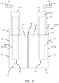
- the oxygen produced is removed from the surface of the anode 107, while the remaining protons (H+) traverse the proton-conductive membrane towards the cathode 105. Simultaneously, electrons travel through the external circuit to reach the cathode 105. At the cathode 105, protons and electrons reunite, resulting in the generation of hydrogen gas.
- the system 1 can include the Polymer Electrolytic Membrane (PEM) and a plurality of ultrasound transducers, placed at optimal locations within the aqueous solution 102.
- the ultrasonic transducers may be positioned close to the anode 107 and/or the cathode 105 but leaving enough space for the aqueous solution 102 to flow easily around the anode 107 and/or the cathode 105.
- ultrasonic transducers may be positioned close to the edges of the reaction vessel 101 to agitate the aqueous solution 102 and move ions towards the anode 107 and/or the cathode 105.
- the PEM 109 is, however, optional and is not required and is omitted in other examples of this disclosure.
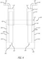
- Figure 4 of the accompanying drawings shows the system 1 without the optional PEM 109.
- the electrodes 105, 107 are circular cross-section rod electrodes.
- the electrodes 105, 107 are inserted into the aqueous solution 102 through a top wall 112 of the reaction vessel 101.
- the electrodes 105, 107 are each flat, rectangular-shaped electrodes positioned parallel to and spaced apart from one another within the reaction vessel 101.
- the electrodes may have different electrode geometries depending on the intended use.
- the electrodes may be flat elongate plates. This geometry would also disrupt any steady, laminar flow within the electrolyte, creating a turbulent vortex and increasing the interaction between water molecules and electrode.
- Electrode/cathode of some examples of this disclosure include, but are not limited to M-shaped electrodes (increasing surface area) (similar to a heat sink), Mesh electrodes (increased surface area) or Porous electrodes (gas diffusion, improved mass transport).
- the electrodes 105, 107 are each mesh or screen electrodes consisting of a mesh or screen structure made of conductive material. These mesh or screen electrodes may be placed vertically on the inner surface of the reaction vessel 101. It is appreciated that various configurations and shapes of electrodes suitable for the intended purpose of electrolysis are contemplated and within the scope of the present invention. Some examples include, but are not limited to, electrodes that are planar and coil-shaped.
- the electrodes 105, 107 may be affected by the chemicals in the aqueous solution 102.
- the choice of electrode material depends on various factors, such as the chemical reaction being performed, the properties of the aqueous solution, and the desired durability and efficiency of the electrodes.
- the cathode 105 and the anode 107 are of graphite, platinum or preferably stainless-steel. In some examples, the cathode 105 and the anode 107 are solid electrodes but in other examples cathode 105 and the anode 107 each comprise an aperture (tubular) or are porous. The structure of cathode 105 and the anode 107 is selected according to the required use and operating parameters of the system 1.
- Platinum electrodes generally have strong corrosion resistance and durability and thus are resistant to deterioration during electrolysis of water. However, platinum electrodes deteriorate over long periods and/or under harsh conditions such as when subjected to a high current density. To minimize or prevent the cathode 105 and the anode 107 from deteriorating during electrolysis, the cathode 105 and the anode 107 may be coated with materials that facilitate better performance and longevity.
- the cathode 105 and the anode 107 are coated with graphene to minimize or prevent the cathode 105 and the anode 107 from deteriorating. This coating not only prevents the cathode 105 and the anode 107 from deteriorating, but also enhances the electrical performance of the cathode 105 and the anode 107.
- Graphene being a 2-D material, is a single layer of carbon atoms arranged in a hexagonal lattice structure, making it resistant to corrosion due to its chemical stability. Moreover, the high electrical conductivity of graphene improves the overall efficiency of the cathode 105 and the anode 107 during the electrolysis process. The electrical conductivity is improved due to the availability of free electrons in the graphene lattice, with the lattice having a hexagonal structure. The presence of Dirac cones in the electronic band structure of graphene indicates the quality of its electrical properties.
- the electronic structure of graphene comprises two conical energy bands meeting at two distinct points (Dirac cones/Dirac Points) which represent the energy dispersion relation for electrons.
- This energy dispersion relation is the product of reduced Planck's constant, the Fermi velocity, and the momentum of the electron.
- the linear relationship between energy and momentum allows the electrons to move with high mobility, presenting excellent electrical conductivity of the material, resulting in higher current densities being handled without deterioration to the electrodes.
- Coating the cathode 105 and the anode 107 with graphene increases the lifespan of the cathode 105 and the anode 107 due to graphene's strong resistance to corrosion in harsh chemical and electrical environments.
- the graphene coating also increases the electrical conductivity property of the cathode 105 and the anode 107 for more efficient operation of the system in performing electrolysis of water to generate hydrogen gas.
- Goldene a 2-D material, that is a single layer of gold atoms.
- Goldene provides similar benefits to graphene.
- gold nanoparticle-based plasmonic photocatalysts driven by the localized surface plasmon resonance excitation of gold nanoparticles can be efficient solar-to-chemical converters due to their wide spectral response and are useful in plasmonic water splitting and H 2 O 2 synthesis from water and oxygen (O 2 ).
- a hydrogen gas collector 113 extends through the top wall 112 of the reaction vessel 101 and is positioned over the cathode 105 to collect hydrogen gas generated during electrolysis.
- An oxygen gas collector 114 extends through the top wall 112 of the reaction vessel 101 and is positioned over the anode 107 to collect oxygen gas generated during electrolysis.
- the hydrogen and oxygen gas collectors 113, 114 are identical or substantially identical to one another and for simplicity the elements of the hydrogen gas collector 113 will be described below.
- the hydrogen and oxygen gas collectors 113, 114 may be different sizes and/or shapes from one another, suitable for the intended purpose of collecting the respective gas.
- a first phase output signal terminal outputs the first phase output signal to the H-bridge circuit.
- a second phase output signal terminal outputs the second phase output signal to the H-bridge circuit.
- a feedback input terminal receives a feedback signal from the H-bridge circuit, the feedback signal is indicative of a parameter of the operation of the H-bridge circuit or the AC drive signal when the H-bridge circuit is driving the ultrasonic transducer 215 with the AC drive signal.
- the sea water is first desalinated to remove the dissolved salts, and then the resulting purified water is electrolyzed to produce hydrogen gas.
- the system 100 is capable of electrolyzing sea water directly to produce hydrogen gas. The expensive and time-consuming process of desalination is eliminated by the systems of some examples of this disclosure.
- ultrasonic waves emitted by the ultrasonic transducer 215 are applied to the sea water, which induces cavitation (formation and collapse of bubbles). This phenomenon creates localized regions of high pressure and temperatures in cavitation bubbles in the sea water for a very short time, leading to increased mass and heat transfer rates. The energy from the cavitation weakens or breaks the hydrogen bonds between water molecules.
- the ultrasonic waves emitted by the ultrasonic transducer 215 displace the solutes present in sea water to facilitate electrolysis proximate to the surface of the cathode 105.
- Improved mass transfer enhances the mixing and movement of reactants near the electrodes 105, 106, improving the distribution of ions in the aqueous solution 102 (sea water).
- the ions move freely within the aqueous solution 102 (sea water) as they would in desalinated sea water with a conventional electrolysis process.
- the systems of examples of this disclosure enable precise control of the frequency and intensity of the ultrasound waves emitted from the ultrasonic transducer to precisely control the system and accommodate for changes in the reaction conditions in the reaction vessel.
- the ultrasound waves reduce dirt formation on the electrodes and promote the formation of more uniform and well-defined electrode surfaces, which improved the efficiency and durability of the electrodes over time.
- ultrasonic transducers are positioned to emit ultrasonic waves upwardly in a direction which is generally aligned with the longitudinal length of the hydrogen or oxygen gas collectors 113, 114.
- the ultrasonic waves emitted by the ultrasonic transducers control the distribution of hydrogen gas bubbles in the aqueous solution 102.
- Having at least one ultrasonic transducer as the source of ultrasound at the base of the respective anode/cathode ensures efficient stirring of the aqueous solution 102.
- the stirring effect exposes more ions to the surface of the anode/cathode for increased gas production.
- Each of the ultrasonic transducers described above is coupled electrically to one or more transducer drivers, such as the transducer driver 202.
- each ultrasonic transducer relative to a respective anode 107 or cathode 105 depends on the specific application and the properties of the aqueous solution 102. Ideally, the transducer is placed in close proximity to the exterior surface 106, 18 of the anode/cathode (either below or to the side of the anode/cathode) to facilitate the formation of cavitation bubbles and enhance the efficiency of the electrolysis process.
- the placement of the ultrasonic transducer in the reaction vessel 101 also depends on the size and geometry of the reaction vessel 101 along with the properties of the aqueous solution 102.
- the size of the reaction vessel 101 affects the rate of electrolysis with the following considerations:
- the rate at which ions reach the cathode 105 and the anode 107 is affected by the distance the ions need to travel to be in contact with the cathode 105 and the anode 107. In smaller reaction vessels, this distance is less, shortening the path for ions to reach the electrodes and resulting in a faster gas production.
- the system 100 comprises a greater number of electrodes than the cathode 105 and the anode 107 of the examples described above.
- Reaction vessel geometry affects the electrolysis process rate due to the following:
- the cathode/anode position is selected based on the geometry of the reaction vessel.
- the spacing between the cathode 105 and the anode 107 is also selected based on the geometry of the reaction vessel 101.
- the distance between the cathode 105 and the anode 107 and their relative positioning affects the quantity of ions contacting them, affecting the reaction rate.
- the shape of the reaction vessel affects the distribution of electrolyte (density of ions) around the cathode 105 and the anode 107.
- electrolyte density of ions
- a uniform electrolyte distribution around the cathode 105 and the anode 107 promotes effective ion transport, increasing reaction rates.
- reaction vessel size optimization requires consideration of the balance between the ion transport distance to the electrodes and the available surface area of electrodes for ions to contact.
- the reaction vessel shape is selected for industrial scale use. This means that the shape of the reaction vessel is adapted for the desired hydrogen gas production capacity, is easy to maintain and operate.
- the reaction vessel size and geometry are parameters that affect the performance, efficiency, and rate of the electrolysis process. Introduction and placement of at least one ultrasonic transducer within the reaction vessel is determined by the reaction vessel's size and geometry. This is also a factor that determines the type of ultrasonic transducer placed within the electrolytic solution.
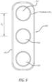
- an ultrasonic transducer array 122 of some examples comprises three ultrasonic transducers 215-217 held by a transducer holder 123.
- Each of the ultrasonic transducers 215-217 has a diameter D T .
- the center of each of the ultrasonic transducers 215-217 is spaced apart from the center of an adjacent one of the ultrasonic transducers 215-217 by a distance S T .
- Figure 10 of the accompanying drawings shows a system of one example with some relevant dimensions labeled.
- the relationships between these dimensions of this example system are summarised in the table show in Figure 11 .
- the dimensions and relationships between the parameters of the components are specific to this described example. This disclosure is not limited to the specific dimension and relationships disclosed herein and other dimensions and relationships are contemplated. For example, those skilled in the art will appreciate that the dimensions and relationships may be modified to scale up the system, for instance for industrial generation of hydrogen gas.
- the anode and the cathode each have a length (l e ) in the range 110% * h v ⁇ l e ⁇ 120%*h v with 70% - 80% of the length (l e ) immersed in the aqueous solution.
- the immersed length of the anode/cathode is denoted as l i .
- the diameter (D e ) of each electrode is 7% ⁇ D v ⁇ 20%.
- each transducer may be 2cm - 5cm.
- other transducer diameters are contemplated, and the selected transducer diameter will depend on the intended use and functionality of the system for generating hydrogen gas.
- the relative dimensions described herein may be scaled up for larger systems for generating hydrogen gas.
- the ultrasonic transducers function using thickness mode vibration to generate ultrasonic waves where the thickness of the ultrasonic transducer is a determining factor for its resonant frequency.
- the ultrasonic transducers function using thickness mode vibration to generate ultrasonic waves where the thickness of the ultrasonic transducer is a determining factor for its resonant frequency.
- other types of ultrasonic transducers are contemplated.
- the spacing between ultrasonic transducers is S T and is set as 1 ⁇ 2*D T .
- the aqueous solution volume can be determined from the maximum fill height (h e ) of 75% to 85% of vessel height.
- Other aqueous solution volumes are, however, contemplated and a skilled person will understand how to calculate the aqueous solution fill volume based on the parameters of the reaction vessel that is configured for an intended purpose.
- the placement of the anode or cathode E s is (25% - 30% of D v + 1 ⁇ 2 * D e ) from the center of the anode/cathode to centre of the cylindrical reaction vessel.
- disc shaped transducers and ultrasonic horns (sonotrodes) of different shapes are selected to transmit ultrasound throughout the electrolytic solution 102 within the reaction vessel 101.
- a system 124 of some examples comprises a membrane-electrode assembly (MEA) 125 for water electrolysis.
- the MEA 125 comprises a Polymer Electrolytic Membrane (PEM) 126 which is positioned or sandwiched between an anode 127 and a cathode 128.
- PEM Polymer Electrolytic Membrane
- the PEM 126 is a Proton Exchange membrane preferably made of perfluoro-sulfonic acid-based materials or similar proton-conducting polymers.
- An example of a PEM is commercially available from Nafion TM of The Chemours Company FC, LLC. of Wilmington, Delaware, USA.
- the PEM 126 conducts protons (H+ ions) and inhibits electron passage.
- the PEM 126 is placed such that it separates the cathode 128 and the anode 127 and facilitates the splitting of water into Hydrogen and Oxygen.
- PEM electrolysis does not require caustic electrolytes, occupies minimal space, and is safer than conventional alkaline electrolysis.
- the oxygen produced is removed from the surface of the anode 127, while the remaining protons (H+) traverse the proton-conductive membrane towards the cathode 128. Simultaneously, electrons travel through the external circuit to reach the cathode 128. At the cathode 128, protons and electrons reunite, resulting in the generation of hydrogen gas.
- the anode 127 and the cathode 128 are each planar or generally planar electrodes. In these examples, the anode 127 and the cathode 128 are each provided with respective gas diffusion layers (GDL). In these examples, the anode 127 and the cathode 128 are each gas diffusion electrodes (GDE) that are preferably made of porous, conductive materials. The anode 127 and the cathode 128 are each preferably coated with at least one catalyst to facilitate electrochemical reactions.
- the anode 127 and the cathode 128 are preferably noble metal electrodes and the oxides of the noble metal(s) are the electrocatalysts (for example, but not limited to, platinum, iridium, iridium dioxide (IrO2), rhodium, rhodium oxide (RhO2)).
- the oxides of the noble metal(s) are the electrocatalysts (for example, but not limited to, platinum, iridium, iridium dioxide (IrO2), rhodium, rhodium oxide (RhO2)).
- the anode 127 and the cathode 128 are each porous and contain interconnected pores or channels throughout its structure. This porosity serves as an enhanced surface area for the catalyst to interact with water molecules, increasing the efficiency of the electrochemical reactions, and proton (H+) diffusion to the cathode side.
- the MEA 125 is positioned within a housing 129 that is preferably a sealed vessel that is configured to enable reactants and products to flow. Seals and gaskets, ensure a tight and secure enclosure resisting the gas and or liquid pressure within the housing 129, and preventing leaks.
- the housing 129 comprises a first housing portion 130 and a second housing portion 131 that are coupled to one another along a seal interface 132.
- the first housing portion 130 comprises side walls 133 that are coupled to an end wall 134.
- a first internal chamber 135 is formed between at least part of the side walls 133 and the end wall 134.
- the anode 127 of the MEA 125 is positioned on an opposite side of the first housing portion 130 to the end wall 134.
- a gas tight or substantially gas tight seal is preferably provided between the anode 127 and the side walls 133.
- An inlet port 136 is provided on the first housing portion 130.
- the inlet port 136 is positioned on the end wall 134.
- the inlet port 136 provides a water flow path to enable water to flow from a water source into the first internal chamber 135.
- An outlet port 137 is provided on the first housing portion 130.
- the outlet port 137 is positioned on the end wall 134 and is spaced apart from the inlet port 136 on an opposite corner of the end wall 134 to the inlet port 136.
- the outlet port 137 provides an oxygen gas and water flow path to enable oxygen gas and water to flow out from the first internal chamber 135 for storage or use.
- the first housing portion 130 comprises an anode connector 138 to enable the anode 127 to be connected to a power source, such as a DC power source 139 as shown in Figure 12 .
- the system 124 comprises at least one ultrasonic transducer 140-146 that is positioned within the first internal chamber 135.
- the system 124 comprises nine ultrasonic transducers 140-146 that are held respectively in three separate transducer holders 147-149 that are coupled to the first housing portion 130.
- Each ultrasonic transducer 140-146 is driven by a respective transducer driver 202 as described herein in relation to the ultrasonic transducer 215.
- the ultrasonic transducers 140-146 emit ultrasonic waves at least partly towards the anode 127 to cause cavitation in water 150 within the first internal chamber 135 proximate to the surface of the anode 127.
- the cavitation weakens hydrogen bonds between water molecules to separate individual water molecules available for interaction with the anode 127 to undergo the oxidation reaction at the anode 127 to oxidize OH- ions and form oxygen gas and H+ ions at the anode 107.
- the H+ ions pass through the PEM 126 to the cathode 128.
- the second housing portion 131 comprises side walls 151 that are coupled to an end wall 152.
- a second internal chamber 153 is formed between at least part of the side walls 151 and the end wall 152.
- the cathode 128 of the MEA 125 is positioned on an opposite side of the second housing portion 131 to the end wall 152.
- a gas tight or substantially gas tight seal is preferably provided between the cathode 128 and the side walls 151.
- At least one hydrogen outlet port 154, 155 is provided on the second housing portion 131.
- two hydrogen outlet ports 154, 155 are provided on the second housing portion 131.
- the hydrogen outlet ports 154, 155 are positioned on the end wall 152.
- Each hydrogen outlet port 154, 155 provides a flow path to enable hydrogen gas to flow from the second internal chamber 153 for storage or use.
- the second housing portion 131 comprises a cathode connector 156 to enable the cathode 128 to be connected to a power source, such as a DC power source 139 as shown in Figure 12 .
- the cathode 128 is a cathode ultrasonic transducer that is driven by a transducer driver 202 or an oscillator to vibrate.
- the vibrations in the cathode 128 help clear any hydrogen gas formed on a surface of the cathode 128 to expose the surface of the cathode 128 to additional H+ ions for generation of hydrogen gas.
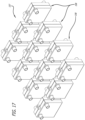
- a system 157 of some examples of this disclosure comprises a plurality of hydrogen generation cells 158.
- Each hydrogen generation cell 158 is a PEM system identical or similar to the system 128 described above.
- the hydrogen generation cells 158 are preferably coupled to one another in an array to produce hydrogen gas from water that is pumped through the hydrogen generation cells 158.
- the operation of the hydrogen generation cells 158 is controlled by the main controller 2 which coordinates the operation of each hydrogen generation cell 158 so the array generates hydrogen gas at a desired rate.
- the main controller 2 activates all or a subset of the hydrogen generation cells 158 to generate hydrogen gas based on a desired hydrogen gas production rate. If the main controller 2 detects that the hydrogen gas production rate of the array is higher than a threshold, then the main controller 2 deactivates one or more of the hydrogen generation cells 158. Conversely, if the main controller 2 detects that the hydrogen gas production rate of the array is lower than the threshold, then the main controller 2 activates one or more of the hydrogen generation cells 158. In this way, the main controller 2 can control the rate of production of hydrogen gas to a safe level for an intended storage volume or use.
- the transducer driver 202 offer precise control to ensure that each ultrasonic transducer is operating at optimal frequency (resonance) to maximize displacement (amplitude/intensity) of the ultrasound wave at the lowest possible power inputs. This is achieved by using the feedback loop function of transducer driver 202, whereby the transducer driver 202 senses the current flowing through the ultrasonic transducer 215 and adjusts the drive frequency of the ultrasonic transducer 215 to maximise the active power consumed by the ultrasonic transducer 215.
- the feedback loop therefore ensures that the transducer driver 202 drives the ultrasonic transducer 215 at or near its resonant (optimum) frequency.
- the feedback loop of the transducer driver 202 is described in detail below.
- multiple ultrasonic transducers are controlled to operate at precise parameters based on their positioning around each other. This ensures that each transducer's ultrasound wave transmission effect on the electrode is maximized and not reduced by the wave from adjacent transducer.
- the transducers are controlled using a single transducer driver 202 with multi-channel transducer control output to drive singular or a plurality of transducers simultaneously.
- microchip In this disclosure, the terms chip, microchip and integrated circuit are interchangeable.
- the microchip or integrated circuit is a single unit which comprises a plurality of interconnected embedded components and subsystems.
- the microchip is, for example, at least partly of a semiconductor, such as silicon, and is fabricated using semiconductor manufacturing techniques.
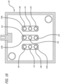
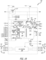
- the transducer driver 202 comprises a second microchip which is referred to herein as a bridge integrated circuit or bridge IC 301 which is electrically connected to the PMIC 300.
- the bridge IC 301 is a microchip for driving a piezoelectric transducer, such as the ultrasonic transducer 215.
- the bridge IC 301 is a single unit which comprises a plurality of interconnected embedded components and subsystems.
- the PMIC 300 and the bridge IC 301 are mounted to the same PCB of the transducer driver 202.
- the voltage control signal VCTL is generated by a digital to analogue converter (DAC) which, in this example, is implemented within the PMIC 300.
- DAC digital to analogue converter
- the DAC is not visible in Figure 18 since the DAC is integrated within the PMIC 300.
- the DAC and the technical benefits of integrating the DAC within the PMIC 300 are described in detail below.
- the PMIC 300 is connected to a power source connector 306 so that the PMIC 300 can receive power from the power supply.
- the microcontroller 303 functions as a master device on the communication bus 302, with the PMIC 300 being a first slave device.
- the communication bus 302 enables the microcontroller 303 to control the following functions within the transducer driver 202:
- the PMIC 300 is, in this example, a self-contained chip or integrated circuit which comprises integrated subsystems and a plurality of pins which provide electrical inputs and outputs to the PMIC 300.
- the references to an integrated circuit or chip in this disclosure are interchangeable and either term encompasses a semiconductor device which may, for instance, be of silicon.
- the PMIC 300 comprises an analogue core 310 which comprises analogue components including a reference block (BG) 311, a LDO 312, a current sensor 313, a temperature sensor 314 and an oscillator 315.
- BG reference block
- LDO LDO
- current sensor current sensor
- temperature sensor 314
- oscillator 315 an oscillator
- the oscillator 315 is coupled to a delay locked loop (DLL) which outputs pulse width modulation (PWM) phases A and B.
- DLL delay locked loop
- PWM pulse width modulation
- the oscillator 315 and the DLL generate a two-phase centre aligned PWM output which drives an H bridge in the bridge IC 301.
- the DLL comprises a plurality of delay lines connected end to end, wherein the total delay of the delay lines is equal to the period of the main clock signal clk_m.
- the DLL is implemented in a digital processor subsystem, referred to herein as a digital core 316, of the PMIC 300 which receives a clock signal from the oscillator 315 and a regulated power supply voltage from the LDO 312.
- the DLL is implemented in a large number (e.g. in the order of millions) of delay gates which are connected end to end in the digital core 316.
- the implementation of the oscillator 315 and the DLL in the same integrated circuit of the PMIC 300 in order to generate a two-phase centre aligned PWM signal is unique since at present no signal generator component in the integrated circuit market comprises this implementation.
- PWM is part of the functionality which enables the transducer driver 202 to track the resonant frequency of the ultrasonic transducer 215 accurately in order to maintain an efficient transfer from electrical energy to kinetic energy in order to optimise the generation of hydrogen gas.
- the PMIC 300 comprises an integrated power switch VSYS which configures the PMIC 300 to power the analogue core 310 by power from a power source.
- the PMIC 300 comprises an embedded analogue to digital converter (ADC) subsystem 318.
- ADC analogue to digital converter
- the implementation of the ADC 318 together with the oscillator 315 in the same integrated circuit is, in itself, unique since there is no other integrated circuit in the integrated circuit market which comprises an oscillator and an ADC implemented as sub-blocks within the integrated circuit.
- an ADC is typically provided as a separate discrete component from an oscillator with the separate ADC and oscillator being mounted to the same PCB.
- the problem with this conventional arrangement is that the two separate components of the ADC and the oscillator take up space unnecessarily on the PCB.
- a further problem is that the conventional ADC and oscillator are usually connected to one another by a serial data communication bus, such as an I2C bus, which has a limited communication speed of up to only 400 kHz.
- the PMIC 300 comprises the ADC 318 and the oscillator 315 integrated within the same integrated circuit which eliminates any lag in communication between the ADC 318 and the oscillator 315, meaning that the ADC 318 and the oscillator 315 can communicate with one another at high speed, such as at the speed of the oscillator 315 (e.g. 20kHz to 40kHz).
- the oscillator 315 is running at 26kHz and generates a clock signal SYS CLOCK at 26kHz. However, in other examples, the oscillator 315 generates a clock signal at a frequency of of 20kHz to 40kHz, preferably 26kHz.
- the integrated circuits described herein are all configured to operate at the high frequency of the oscillator 315.
- the ADC 318 comprises a plurality of feedback input terminals or analogue inputs 319 which comprise a plurality of GPIO inputs (IF_GPIO1-3).
- At least one of the feedback input terminals or the analogue inputs 319 receives the gas pressure signal from the pressure sensor 117.
- At least one of the other feedback input terminals or the analogue inputs 319 receives a feedback signal from an H-bridge circuit in the bridge IC 301, the feedback signal being indicative of a parameter of the operation of the H-bridge circuit or an AC drive signal when the H-bridge circuit is driving the ultrasonic transducer 215 with the AC drive signal.
- the GPIO inputs are used to receive a current sense signal from the bridge IC 301 which is indicative of the route mean square (rms) current reported by the bridge IC 301.
- one of the GPIO inputs is a feedback input terminal which receives a feedback signal from the H-bridge in the bridge IC 301.
- the ADC subsystem 318 samples analogue signals received at the plurality of ADC input terminals 319 at a sampling frequency which is proportional to the frequency of the main clock signal. The ADC subsystem 318 then generates ADC digital signals using the sampled analogue signals.
- the ADC 318 which is incorporated in the PMIC 300 samples not only the RMS current flowing through the H-bridge 334 and the ultrasonic transducer 215 but also voltages available in the system (e.g. VBOOST), the temperature of the PMIC 300 and the GPIO inputs (IF_GPIO1-3).
- the digital core 316 receives the ADC generated digital signals from the ADC subsystem and processes the ADC digital signals to generate the driver control signal.
- the digital core 316 communicates the driver control signal to the PWM signal generator subsystem (DLL 332) to control the PWM signal generator subsystem.
- DLL 332 PWM signal generator subsystem
- Rectification circuits existing in the market today have a very limited bandwidth. Since the oscillator 315 of the PMIC 300 is capable of running at a wide range of 20kHz to 5MHz a high bandwidth rectifier circuit is implemented in the PMIC 300. As will be described below, sensing the RMS current within an H bridge of the bridge IC 301 forms part of a feedback loop which enables the transducer driver 202 to drive the ultrasonic transducer 215 with high precision.
- the feedback loop is a game changer in the industry of driving ultrasound transducers since it accommodates for any process variation in the piezoelectric transducer production (variations of resonance frequencies) and it compensates for temperature effects of the resonance frequency.
- the ADC 318 comprises voltage monitoring inputs VMON and VRTH as well as a temperature monitoring input TEMP.
- the temperature monitoring input TEMP receives a temperature signal from the temperature sensor 314 which is embedded within the PMIC 300. This enables the PMIC 300 to sense the actual temperature within the PMIC 300 accurately so that the PMIC 300 can detect any malfunction within the PMIC 300 as well as malfunction to other components on the printed circuit board which affect the temperature of the PMIC 300.
- the PMIC 300 can then control the bridge IC 301 to prevent excitation of the ultrasonic transducer 215 if there is a malfunction in order to maintain the safety of the system.
- the PMIC 300 comprises a first digital to analogue converter (DAC) 327 which converts digital signals within the PMIC 300 into an analogue voltage control signal which is output from the PMIC 300 via an output pin VDAC0.
- the first DAC 327 converts a digital control signal generated by the digital core 316 into an analogue voltage control signal which is output via the output pin VDAC0 to control a voltage regulator circuit, such as the boost converter 305.
- the voltage control signal thus controls the voltage regulator circuit to generate a predetermined voltage for modulation by the H-bridge circuit to drive the ultrasonic transducer 215 in response to feedback signals which are indicative of the operation of the ultrasonic transducer 215.
- the PMIC 300 comprises a second DAC 328 which converts digital signals within the PMIC 300 into an analogue signal which is output from the PMIC 300 via a second analogue output pin VDAC1.
- Embedding the DAC 327 or the DACs 327, 328 within the same microchip as the other subsystems of the PMIC 300 allows the DACs 327, 328 to communicate with the digital core 316 and other components within the PMIC 300 at high speed with no or minimal communication lag.
- the DACs 327, 328 provide analogue outputs which control external feedback loops.
- the first DAC 327 provides the control signal VCTL to the boost converter 305 to control the operation of the boost converter 305.
- the DACs 327, 328 are configured to provide a drive signal to a DC-DC buck converter instead of or in addition to the boost converter 305.
- Integrating the two independent DAC channels in the PMIC 300 enables the PMIC 300 to manipulate the feedback loop of any regulator used in the transducer driver 202 and allows the transducer driver 202 to regulate the sonication power of the ultrasonic transducer 215 or to set analogue thresholds for absolute maximum current and temperature settings of the ultrasonic transducer 215.
- the PMIC 300 also comprises various functional blocks which include a digital machine (FSM) to implement the functionality of the microchip. These blocks will be described in more detail below.
- FSM digital machine
- a pulse width modulation (PWM) signal generator subsystem 329 is embedded within the PMIC 300.
- the PWM generator system 329 comprises the oscillator 315, and frequency divider 330, a multiplexer 331 and a delay locked loop (DLL) 332.
- DLL delay locked loop
- the PWM generator system 329 is a two phase centre aligned PWM generator.
- the frequency divider 330, the multiplexer 331 and the DLL 332 are implemented in digital logic components (e.g. transistors, logic gates, etc.) within the digital core 316.
- the frequency range which is covered by the oscillator 315 and respectively by the PWM generator system 329 is 20 kHz to 5 MHz or of 20kHz to 40kHz, preferably 26kHz.
- the frequency accuracy of the PWM generator system 329 is ⁇ 1% and the spread over temperature is ⁇ 1%.
- no IC has an embedded oscillator and two phase centre aligned PWM generator that can provide a frequency range of 20kHz to 5MHz.
- the IC of some examples of this disclosure is capable of providing a frequency range of 20kHz up to 105MHz.
- the oscillator 315 generates a main clock signal (clk_m) with a frequency of 20kHz to 5 MHz or of 20kHz to 40kHz, preferably 26kHz.
- the main clock clk_m is input to the frequency divider 330 which divides the frequency of the main clock clk_m by one or more predetermined divisor amounts.
- the frequency divider 330 divides the frequency of the main clock clk_m by 2, 4, 8 and 16 and provides the divided frequency clocks as outputs to the multiplexer 331.
- the multiplexer 331 multiplexes the divided frequency clocks and provides a divided frequency output to the DLL 332.
- This signal which is passed to the DLL 332 is a frequency reference signal which controls the DLL 332 to output signals at a desired frequency.
- the frequency divider 330 and the multiplexer 331 are omitted.
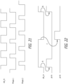
- the oscillator 315 also generates two phases; a first phase clock signal Phase 1 and a second phase clock signal Phase 2.
- the phases of the first phase clock signal and the second phase clock signal are centre aligned. As illustrated in Figure 21 :
- Phase 1 and Phase 2 are then sent to the DLL 332 which generates a double frequency clock signal using the first phase clock signal Phase 1 and the second phase clock signal Phase 2.
- the double frequency clock signal is double the frequency of the main clock signal clk_m.
- an "OR" gate within the DLL 332 generates the double frequency clock signal using the first phase clock signal Phase 1 and the second phase clock signal Phase 2.
- This double frequency clock or the divided frequency coming from the frequency divider 330 is selected based on a target frequency selected and then used as reference for the DLL 332.
- a signal referred to hereafter as “clock” represents the main clock clk_m multiplied by 2
- a signal referred to hereafter as “clock_del” is a replica of clock delayed by one period of the frequency.
- Clock and clock_del are passed through a phase frequency detector.
- a node Vc is then charged or discharged by a charge-pump based on the phase error polarity.
- a control voltage is fed directly to control the delay of every single delay unit within the DLL 332 until the total delay of the DLL 332 is exactly one period.
- the DLL 332 controls the rising edge of the first phase clock signal Phase 1 and the second phase clock signal Phase 2 to be synchronous with the rising edge of the double frequency clock signal.
- the DLL 332 adjusts the frequency and the duty cycle of the first phase clock signal Phase 1 and the second phase clock signal Phase 2 in response to a respective frequency reference signal and a duty cycle control signal to produce a first phase output signal Phase A and a second phase output signal Phase B to drive an H-bridge or an inverter to generate an AC drive signal to drive an ultrasonic transducer.
- the PMIC 300 comprises a first phase output signal terminal PHASE_A which outputs the first phase output signal Phase A to an H-bridge circuit and a second phase output signal terminal PHASE_B which outputs the second phase output signal Phase B to an H-bridge circuit.
- the DLL 332 adjusts the duty cycle of the first phase clock signal Phase 1 and the second phase clock signal Phase 2 in response to the duty cycle control signal by varying the delay of each delay line in the DLL 332 response to the duty cycle control signal.
- the clock is used at double its frequency because this guarantees better accuracy.
- the frequency of the main clock clk_m which it is not in examples of this disclosure
- Phase A is synchronous with clock's rising edge R
- Phase B is synchronous with clock's falling edge F.
- the delay line of the DLL 332 controls the rising edge R and so, for the falling edge F, the PWM generator system 329 would need to rely on a perfect matching of the delay units of the DLL 332 which can be imperfect.
- the PWM generator system 329 uses the double frequency clock so that both Phase A and Phase B are synchronous with the rising edge R of the double frequency clock.
- the delay line of the DLL 332 comprises 25 delay units, with the output of each respective delay unit representing a Phase nth. Eventually the phase of the output of the final delay unit will correspond to the input clock. Considering that all delays will be almost the same, a particular duty cycle is obtained with the output of the specific delay unit with simple logic in the digital core 316.
- a start-up circuit is implemented in the PWM generator system 329 which allows the DLL 332 to start from a known and deterministic condition.
- the start-up circuit furthermore allows the DLL 332 to start with the minimum delay.
- the frequency range covered by the PWM generator system 329 is extended and so the delay units in the DLL 332 can provide delays of 4 ns (for an oscillator frequency of 5 MHz) to 400 ns (for an oscillator frequency of 50 kHz).
- capacitors Cb are included in the PWM generator system 329, with the capacitor value being selected to provide the required delay.
- the Phase A and Phase B are output from the DLL 332 and passed through a digital IO to the bridge IC 301 so that the Phase A and Phase B can be used to control the operation of the bridge IC 301.
- ADC analogue to digital converter
- the ADC 318 samples at least one parameter within the ultrasonic transducer driver chip (PMIC 300) at a sampling rate which is equal to the frequency of the main clock signal clk_m.
- the ADC 318 is a 10 bit analogue to digital converter which is able to unload digital sampling from the microprocessor 303 to save the resources of the microprocessor 303. Integrating the ADC 318 within the PMIC 300 also avoids the need to use an I2C bus that would otherwise slow down the sampling ability of the ADC (a conventional device relies on an I2C bus to communicate data between a dedicated discrete ADC and a microcontroller at a limited clock speed of typically up to 400 kHz).
- one or more of the following parameters can be sampled sequentially by the ADC 318:
- the ADC 318 samples one or more of the above-mentioned sources sequentially, for instance in a round robin scheme.
- the ADC 318 samples the sources at high speed, such as the speed of the oscillator 315 which may be 20kHz to 5MHz.
- the device 202 is configured so that a user or the manufacturer of the device can specify how many samples shall be taken from each source for averaging. For instance, a user can configure the system to take 512 samples from the rms current input, 64 samples from the battery voltage, 64 from the charger input voltage, 32 samples from the external pins and 8 from the NTC pin. Furthermore, the user can also specify if one of the above-mentioned sources shall be skipped.
- the user can specify two digital thresholds which divide the full range into a plurality of zones, such as 3 zones. Subsequently the user can set the system to release an interrupt when the sampled value changes zones e.g. from a zone 2 to a zone 3.
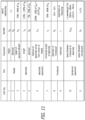
- the PMIC 300 comprises an 8 bit general purpose digital input output port (GPIO). Each port can be configured as digital input and digital output. Some of the ports have an analogue input function, as shown in the table in Figure 23 .
- GPIO general purpose digital input output port
- the GPIO7-GPIO5 ports of the PMIC 300 can be used to set the device's address on the communication (12C) bus 302. Subsequently eight identical devices can be used on the same I2C bus. This is a unique feature in the IC industry since it allows eight identical devices to be used on the same I2C bus without any conflicting addresses. This is implemented by each device reading the state of GPIO7-GPIO5 during the first 100 ⁇ s after the startup of the PMIC 300 and storing that portion of the address internally in the PMIC 300. After the PMIC 300 has been started up the GPIOs can be used for any other purpose.
- the PMIC 300 comprises a six channel LED driver 320.
- the LED driver 320 comprises N-Channel Metal-Oxide Semiconductor (NMOS) current sources which are 5V tolerant.
- NMOS N-Channel Metal-Oxide Semiconductor
- the LED driver 320 is configured to set the LED current in four discrete levels; 5mA, 10mA, 15mA and 20mA.
- the LED driver 320 is configured to dim each LED channel with a 12 bit PWM signal either with or without gamma correction.
- the LED driver 320 is configured to vary the PWM frequency from 300 Hz to 1.5 KHz.
- the PMIC 300 comprises two independent 6 Bit Digital to Analog Converters (DAC) 327, 328 which are incorporated into the PMIC 300.
- the purpose of the DACs 327, 328 is to output an analogue voltage to manipulate the feedback path of an external regulator (e.g. the DC-DC Boost converter 305 a Buck converter or a LDO).
- the DACs 327, 328 can also be used to dynamically adjust the over current shutdown level of the bridge IC 301, as described below.
- each DAC 327, 328 is programmable between 0V and 1.5V or between 0V and V_battery (Vbat).
- the control of the DAC output voltage is done via I2C commands. Having two DAC incorporated in the PMIC 300 is unique and will allow the dynamic monitoring control of the current. If either DAC 327, 328 was an external chip, the speed would fall under the same restrictions of speed limitations due to the I2C protocol.
- An active power monitoring arrangement of the device 202 works with optimum efficiency if all these embedded features are in the PMIC. Had they been external components, the active power monitoring arrangement would be totally inefficient.
- the bridge IC 301 is a microchip which comprises an embedded power switching circuit 333.
- the power switching circuit 333 is an H-bridge 334 which is shown in Figure 25 and which is described in detail below. It is, however, to be appreciated that the bridge IC 301 of other examples may incorporate an alternative power switching circuit to the H-bridge 334, provided that the power switching circuit performs an equivalent function for generating an AC drive signal to drive the ultrasonic transducer 215.
- the bridge IC 301 comprises a first phase terminal PHASE A which receives a first phase output signal Phase A from the PWM signal generator subsystem of the PMIC 300.
- the bridge IC 301 also comprises a second phase terminal PHASE B which receives a second phase output signal Phase B from the PWM signal generator subsystem of the PMIC 300.
- the bridge IC 301 comprises a current sensing circuit 335 which senses current flow in the H-bridge 334 directly and provides an RMS current output signal via the RMS_CURR pin of the bridge IC 301.
- the current sensing circuit 335 is configured for over current monitoring, to detect when the current flowing in the H-bridge 334 is above a predetermined threshold.
- the integration of the power switching circuit 333 comprising the H-bridge 334 and the current sensing circuit 335 all within the same embedded circuit of the bridge IC 301 is a unique combination in the IC market. At present, no other integrated circuit in the IC market comprises an H-bridge with embedded circuitry for sensing the RMS current flowing through the H-bridge.
- the bridge IC 301 comprises a temperature sensor 336 which includes over temperature monitoring.
- the temperature sensor 336 is configured to shut down the bridge IC 301 or disable at least part of the bridge IC 336 in the event that the temperature sensor 336 detects that the bridge IC 301 is operating at a temperature above a predetermined threshold.
- the temperature sensor 336 therefore provides an integrated safety function which prevents damage to the bridge IC 301 or other components within the transducer driver 202 in the event that the bridge IC 301 operates at an excessively high temperature.
- the bridge IC 301 comprises a digital state machine 337 which is integrally connected to the power switching circuit 333.
- the digital state machine 337 receives the phase A and phase B signals from the PMIC 300 and an ENABLE signal, for instance from the microcontroller 303.
- the digital state machine 337 generates timing signals based on the first phase output signal Phase A and the second phase output signal Phase B.
- the digital state machine 337 outputs timing signals corresponding to the phase A and phase B signals as well as a BRIDGE PR and BRIDGE EN signals to the power switching circuit 333 in order to control the power switching circuit 333.
- the digital state machine 337 thus outputs the timing signals to the switches T 1 -T 4 of the H-bridge circuit 334 to control the switches T 1 -T 4 to turn on and off in a sequence such that the H-bridge circuit outputs an AC drive signal for driving the ultrasonic transducer 215.
- the switching sequence comprises a free-float period in which the first switch T 1 and the second switch T 1 are turned off and the third switch T 3 and the fourth switch T 4 are turned on in order to dissipate energy stored by the ultrasonic transducer 215.
- the bridge IC 301 comprises a test controller 338 which enables the bridge IC 301 to be tested to determine whether the embedded components within the bridge IC 301 are operating correctly.
- the test controller 338 is coupled to TEST_DATA, TEST_CLK and TEST_LOAD pins so that the bridge IC 301 can be connected to an external control device which feeds data into and out from the bridge IC 301 to test the operation of the bridge IC 301.
- the bridge IC 301 also comprises a TEST BUS which enables the digital communication bus within the bridge IC 301 to be tested via a TST_PAD pin.
- the bridge IC 301 comprises a power on reset circuit (POR) 339 which controls the startup operation of the bridge IC 301.
- POR power on reset circuit
- the POR 339 ensures that the bridge IC 301 starts up properly only if the supply voltage is within a predetermined range. If the power supply voltage is outside of the predetermined range, for instance if the power supply voltage is too high, the POR 339 delays the startup of the bridge IC 301 until the supply voltage is within the predetermined range.
- the bridge IC 301 comprises a reference block (BG) 340 which provides a precise reference voltage for use by the other subsystems of the bridge IC 301.
- BG reference block
- the bridge IC 301 comprises a current reference 341 which provides a precise current to the power switching circuit 333 and/or other subsystems within the bridge IC 301, such as the current sensor 335.
- the temperature sensor 336 monitors the temperature of the silicon of the bridge IC 301 continuously. If the temperature exceeds the predetermined temperature threshold, the power switching circuit 333 is switched off automatically. In addition, the over temperature may be reported to an external host to inform the external host that an over temperature event has occurred.
- the digital state machine (FSM) 337 generates the timing signals for the power switching circuit 333 which, in this example, are timing signals for controlling the H-bridge 334.
- the bridge IC 301 comprises comparators 342,343 which compare signals from the various subsystems of the bridge IC 301 with the voltage and current references 340,341 and provide reference output signals via the pins of the bridge IC 301.
- the H-bridge 334 of this example comprises four switches in the form of NMOS field effect transistors (FET) switches on both sides of the H-bridge 334.
- the H-bridge 334 comprises four switches or transistors T 1 -T 4 which are connected in an H-bridge configuration, with each transistor T 1 -T 4 being driven by a respective logic input A-D.
- the transistors T 1 -T 4 are configured to be driven by a bootstrap voltage which is generated internally with two external capacitors Cb which are connected as illustrated in Figure 25 .
- the H-bridge 334 comprises various power inputs and outputs which are connected to the respective pins of the bridge IC 301.
- the H-bridge 334 receives the programmable voltage VBOOST which is output from the boost converter 305 via a first power supply terminal, labelled VBOOST in Figure 25 .
- the H-bridge 334 comprises a second power supply terminal, labelled VSS_P in Figure 25 .
- the H-bridge 334 comprises outputs OUTP, OUTN which are configured to connect to respective terminals of the ultrasonic transducer 215 so that the AC drive signal output from the H-bridge 334 can drive the ultrasonic transducer 215.
- the switching of the four switches or transistors T 1 -T 4 is controlled by switching signals from the digital state machine 337 via the logic input A-D. It is to be appreciated that, while Figure 25 shows four transistors T 1 -T 4 , in other examples, the H-bridge 334 incorporates a larger number of transistors or other switching components to implement the functionality of the H-bridge.
- the H-bridge 334 operates at a switching power of 22 W to 50 W in order to deliver an AC drive signal with sufficient power to drive the ultrasonic transducer 215 optimally at or near the resonant frequency of the ultrasonic transducer 215.
- the voltage which is switched by the H-bridge 334 of this example is ⁇ 15 V. In other examples, the voltage is ⁇ 20 V.
- the voltage which is switched by the H-bridge 334 of this example is 100 V - 500 V with a power output of 200 W - 2500 W.
- the H-bridge 334 switches at a frequency of of 20kHz to 40kHz, preferably 26kHz.
- the bridge IC 301 described herein no conventional integrated circuit H-bridge available in the IC market is able to operate at a power of 22 V to 50 V at a frequency range of 26kHz to 5MHz.
- the current sensor 335 comprises positive and negative current sense resistors RshuntP, RshuntN which are connected in series with the respective high and low sides of the H-bridge 334, as shown in Figure 25 .
- the current sense resistors RshuntP, RshuntN are low value resistors which, in this example, are 0.1 ⁇ .
- the current sensor 335 comprises a first voltage sensor in the form of a first operational amplifier 344 which measures the voltage drop across the first current sensor resistor RshuntP and a second voltage sensor in the form of a second operational amplifier 345 which measures the voltage drop across the second current sensor resistor RshuntN.
- the gain of each operational amplifier 344, 345 is 2V/V.
- each operational amplifier 344, 345 is, in this example, 1mA/V.
- the current sensor 335 comprises a pull down resistor Rcs which, in this example, is 2k ⁇ .
- the outputs of the operational amplifiers 344, 345 provide an output CSout which passes through a low pass filter 346 which removes transients in the signal CSout.
- An output Vout of the low pass filter 346 is the output signal of the current sensor 335.
- the current sensor 335 thus measures the AC current flowing through the H-bridge 334 and respectively through the ultrasonic transducer 215.
- the current sensor 335 translates the AC current into an equivalent RMS output voltage (Vout) relative to ground.
- the current sensor 335 has high bandwidth capability since the H-bridge 334 can be operated at a frequency of of 26kHz to 5MHz, preferably 20kHz to 40kHz, preferably 26kHz.
- the output Vout of the current sensor 335 reports a positive voltage which is equivalent to the measured AC rms current flowing through the ultrasonic transducer 215.
- the output voltage Vout of the current sensor 335 is, in this example, fed back to the control circuitry within the bridge IC 301 to enable the bridge IC 301 to shut down the H-bridge 334 in the event that the current flowing through the H-bridge 334 and hence through the transducer 215 is in excess of a predetermined threshold.
- the over current threshold event is reported to the first comparator 342 in the bridge IC 301 so that the bridge IC 301 can report the over current event via the OVC_TRIGG pin of the bridge IC 301.
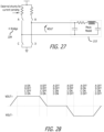
- FIG. 28 A graph showing the output voltage OUTP, OUTN of the H-bridge 334 according to the above switching sequence is shown in Figure 28 of the accompanying drawings.
- the zero output voltage portion of the switching sequence is included to accommodate for the energy stored by the ultrasonic transducer 215 (e.g. the energy stored by the capacitors in the equivalent circuit of the ultrasonic transducer). As described above, this minimises the voltage overshoot in the switching waveform voltage which is applied to the ultrasonic transducer and hence minimises unnecessary power dissipation and heating in the ultrasonic transducer.
- Minimising or removing voltage overshoot also reduces the risk of damage to transistors in the bridge IC 301 by preventing the transistors from being subject to voltages in excess of their rated voltage. Furthermore, the minimisation or removal of the voltage overshoot enables the bridge IC 301 to drive the ultrasonic transducer accurately in a way which minimises disruption to the current sense feedback loop described herein. Consequently, the bridge IC 301 is able to drive the ultrasonic transducer at a power of 22 W to 50 W or 70 W. In some examples, the bridge IC 301 is able to drive the ultrasonic transducer at a frequency of 20 kHz to 5 MHz. In other examples, the bridge IC 301 is able to drive the ultrasonic transducer at a frequency of 20 kHz to 40 kHz.
- the bridge IC 301 of this example is configured to be controlled by the PMIC 300 to operate in two different modes, referred to herein as a forced mode and a native frequency mode. These two modes of operation are novel over existing bridge ICs.
- the native frequency mode is a major innovation which offers substantial benefits in the accuracy and efficiency of driving an ultrasonic transducer as compared with conventional devices.
- the H-bridge 334 is controlled in the sequence described above but at a user selectable frequency.
- the H-bridge transistors T 1 -T 4 are controlled in a forced way irrespective of the inherent resonant frequency of the ultrasonic transducer 215 to switch the output voltage across the ultrasonic transducer 215.
- the forced frequency mode therefore allows the H-bridge 334 to drive the ultrasonic transducer 215, which has a resonant frequency f1, at different frequency f2.
- Driving an ultrasonic transducer at a frequency which is different from its resonant frequency may be appropriate in order to adapt the operation to different applications. For example, it may be appropriate to drive an ultrasonic transducer at a frequency which is slightly off the resonance frequency (for mechanical reasons to prevent mechanical damage to the transducer). Alternatively, it may be appropriate to drive an ultrasonic transducer at a low frequency but the ultrasonic transducer has, because of its size, a different native resonance frequency.
- the transducer driver 202 controls the bridge IC 301 to drive the ultrasonic transducer 215 in the forced frequency mode in response to the configuration of the transducer driver 202 for a particular application or a particular ultrasonic transducer.
- the following native frequency mode of operation is a significant development and provides benefits in improved accuracy and efficiency over conventional ultrasonic drivers that are available on the IC market today.
- the native frequency mode of operation follows the same switching sequence as described above but the timing of the zero output portion of the sequence is adjusted to minimise or avoid problems that can occur due to current spikes in the forced frequency mode operation. These current spikes occur when the voltage across the ultrasonic transducer 215 is switched to its opposite voltage polarity.
- An ultrasonic transducer which comprises a piezoelectric crystal has an electrical equivalent circuit which incorporates a parallel connected capacitor (e.g. see the piezo model in Figure 27 ). If the voltage across the ultrasonic transducer is hard-switched from a positive voltage to a negative voltage, due to the high dV/dt there can be a large current flow current flow as the energy stored in the capacitor dissipates.
- the native frequency mode avoids hard switching the voltage across the ultrasonic transducer 215 from a positive voltage to a negative voltage (and vice versa). Instead, prior to applying the reversed voltage, the ultrasonic transducer 215 (piezoelectric crystal) is left free-floating with zero voltage applied across its terminals for a free-float period.
- the PMIC 300 sets the drive frequency of the bridge IC 301 such that the bridge 334 sets the free-float period such that current flow inside the ultrasonic transducer 215 (due to the energy stored within the piezoelectric crystal) reverses the voltage across the terminals of the ultrasonic transducer 215 during the free-float period.
- the PMIC 300 controls the power delivered through the H-bridge 334 to the ultrasonic transducer 215 to a first value which is a low value (e.g. 5 V).
- the PMIC 300 then controls the power delivered through the H-bridge 334 to the ultrasonic transducer 215 to increase over a period of time to a second value (e.g. 15 V) which is higher than the first value in order to build up the energy stored within the ultrasonic transducer 215.
- a second value e.g. 15 V
- Current spikes still occur during this ramp of the oscillation until the current inside the ultrasonic transducer 215 developed sufficiently.
- those current spikes are kept sufficiently low to minimise the impact on the operation of the ultrasonic transducer 215.
- the transducer driver 202 controls the frequency of the oscillator 315 and the duty cycle (ratio of turn-on time to free-float time) of the AC drive signal output from the H-bridge 334 with high precision.
- the transducer driver 202 performs three control loops to regulate the oscillator frequency and the duty cycle such that the voltage reversal at the terminals of the ultrasonic transducer 215 is as precise as possible and current spikes are minimised or avoided as far as possible.
- the precise control of the oscillator and the duty cycle using the control loops is a significant advance in the field of IC ultrasonic drivers.
- the current sensor 335 senses the current flowing through the ultrasonic transducer 215 during the free-float period.
- the digital state machine 337 adapts the timing signals to switch on either the first switch T1 or the second switch T2 when the current sensor 335 senses that the current flowing through the ultrasonic transducer 215 during the free-float period is zero.
- FIG 29 of the accompanying drawings shows the oscillator voltage waveform 347 (V(osc)), a switching waveform 348 resulting from the turn-on and turn-off the left hand side high switch T1 of the H-bridge 334 and a switching waveform 349 resulting from the turn-on and turn-off the right hand side high switch T2 of the H-bridge 334.
- V(osc) the oscillator voltage waveform 347
- switching waveform 348 resulting from the turn-on and turn-off the left hand side high switch T1 of the H-bridge 334
- a switching waveform 349 resulting from the turn-on and turn-off the right hand side high switch T2 of the H-bridge 334.
- both high switches T1, T2 of the H-bridge 334 are turned off (free-floating phase).
- the duration of the free-float period 350 is controlled by the magnitude of the free-float control voltage 351 (Vphioff).
- FIG. 30 of the accompanying drawings shows the voltage waveform 352 at a first terminal of the ultrasonic transducer 215 (the voltage waveform is reversed at the second terminal of the ultrasonic transducer 215) and the piezo current 353 flowing through the ultrasonic transducer 215.
- the piezo current 353 represents an (almost) ideal sinusoidal waveform (this is never possible in the forced frequency mode or in any bridge in the IC market).
- the left hand side high switch T1 of the H-bridge 334 is turned off (here, the switch T1 is turned off when the piezo current 353 is approximately 6 A).
- the remaining piezo current 353 which flows within the ultrasonic transducer 215 due to the energy stored in the ultrasonic transducer 215 (the capacitor of the piezo equivalent circuit) is responsible for the voltage reversal during the free-float period 350.
- the piezo current 353 decays to zero during the free-float period 350 and into negative current flow domain thereafter.
- the native frequency mode has at least three advantages:
- the PMIC 300 starts by controlling the bridge IC 301 to drive the ultrasonic transducer 215 at a frequency above the resonance of the piezo crystal.
- the PMIC 300 then controls the bridge IC 301 to that the frequency of the AC drive signal decays/reduces during start up.
- the piezo current will develop/increase rapidly.
- the frequency decay/reduction is stopped by the PMIC 300.
- the control loops of the PMIC 300 then take over the regulation of frequency and duty cycle of the AC drive signal.
- the power delivered to the ultrasonic transducer 215 is controlled through the duty cycle and/or a frequency shift and/or by varying the supply voltage.
- the power delivered to the ultrasonic transducer 215 controlled only through the supply voltage.
- the bridge IC 301 is configured to measure the length of time taken for the current flowing through the ultrasonic transducer 215 to fall to zero when the first switch T 1 and the second switch T 2 are turned off and the third switch T 3 and the fourth switch T 4 are turned on. The bridge IC 301 then sets the length of time of the free-float period to be equal to the measured length of time.
- the PMIC 300 and the bridge IC 301 of this example are designed to work together as a companion chip set.
- the PMIC 300 and the bridge IC 301 are connected together electrically for communication with one another.
- there are interconnections between the PMIC 300 and the bridge IC 301 which enable the following two categories of communication:
- the connections between the CS, OC and OT pins of the PMIC 300 and the bridge IC 301 carry CS (current sense), OC (over current) and OT (over temperature) feedback signals from the bridge IC 301 back to the PMIC 300.
- the CS (current sense) feedback signal comprises a voltage equivalent to the rms current flowing through the ultrasonic transducer 215 which is measured by the current sensor 335 of the bridge IC 301.
- the OC (over current) and OT (over temperature) feedback signals are digital signals indicating that either an over current or an over voltage event has been detected by the bridge IC 301.
- the thresholds for the over current and over temperature are set with an external resistor.
- the thresholds can also be dynamically set in response to signals passed to the OC_REF pin of the bridge IC 301 from one of the two DAC channels VDAC0, VDAC1 from the PMIC 300.
- the design of the PMIC 300 and the bridge IC 301 allow the pins of these two integrated circuits to be connected directly to one another (e.g. via copper tracks on a PCB) so that there is minimal or no lag in the communication of signals between the PMIC 300 and the bridge IC 301.
- This provides a significant speed advantage over conventional bridges in the IC market which are typically controlled by signals via a digital communications bus.
- a standard I2C bus is clocked at only 400 kHz, which is too slow for communicating data sampled at the high clock speeds of of 2MHz to 5MHz.
- the volume of hydrogen produced by the systems of some examples of this disclosure may be calculated follows:
- the systems of examples of this disclosure do not require sea water to be desalinated prior to electrolysis. Sea water can be used directly as the electrolytic solution.
- the configuration of the transducer driver and the feedback loop determines and implements the optimum balance between frequency and intensity of the ultrasound flowing through the electrolytic solution to maximize hydrogen production.
- a frequency of 20kHz to 40kHz is set by the transducer driver to produce an optimum balance for a high electrolysis reaction rate.
- a frequency an intensity of 0.1Wcm -2 ⁇ 0.02Wcm -2 is set by the transducer driver to produce an optimum balance for a high electrolysis reaction rate.
- exemplary is used herein to mean serving as an example, instance, illustration, etc., and not necessarily as advantageous.
- “or” is intended to mean an inclusive “or” rather than an exclusive “or”.
- “a” and “an” as used in this application and the appended claims are generally be construed to mean “one or more” unless specified otherwise or clear from context to be directed to a singular form.
- at least one of A and B and/or the like generally means A or B or both A and B.
- such terms are intended to be inclusive in a manner similar to the term “comprising”.
- first,” “second,” or the like are not intended to imply a temporal aspect, a spatial aspect, an ordering, etc. Rather, such terms are merely used as identifiers, names, etc. for features, elements, items, etc.
- a first element and a second element generally correspond to element A and element B or two different or two identical elements or the same element.
- Examples or embodiments of the subject matter and the functional operations described herein can be implemented in digital electronic circuitry, or in computer software, firmware, or hardware, including the structures disclosed in this specification and their structural equivalents, or in combinations of one or more of them.
- Some examples or embodiments are implemented using one or more modules of computer program instructions encoded on a computer-readable medium for execution by, or to control the operation of, a data processing apparatus.
- the computer-readable medium can be a manufactured product, such as hard drive in a computer system or an embedded system.
- the computer-readable medium can be acquired separately and later encoded with the one or more modules of computer program instructions, such as by delivery of the one or more modules of computer program instructions over a wired or wireless network.
- the computer-readable medium can be a machine-readable storage device, a machine-readable storage substrate, a memory device, or a combination of one or more of them.
- the terms “computing device” and “data processing apparatus” encompass all apparatus, devices, and machines for processing data, including by way of example a programmable processor, a computer, or multiple processors or computers.
- the apparatus can include, in addition to hardware, code that creates an execution environment for the computer program in question, e.g., code that constitutes processor firmware, a protocol stack, a database management system, an operating system, a runtime environment, or a combination of one or more of them.
- the apparatus can employ various different computing model infrastructures, such as web services, distributed computing and grid computing infrastructures.
- processors suitable for the execution of a computer program include, by way of example, both general and special purpose microprocessors, and any one or more processors of any kind of digital computer.
- a processor will receive instructions and data from a read-only memory or a random access memory or both.
- the essential elements of a computer are a processor for performing instructions and one or more memory devices for storing instructions and data.
- a computer will also include, or be operatively coupled to receive data from or transfer data to, or both, one or more mass storage devices for storing data, e.g., magnetic, magnetooptical disks, or optical disks.
- mass storage devices for storing data, e.g., magnetic, magnetooptical disks, or optical disks.
- Devices suitable for storing computer program instructions and data include all forms of non-volatile memory, media and memory devices.
- the invention may also broadly consist in the parts, elements, steps, examples and/or features referred to or indicated in the specification individually or collectively in any and all combinations of two or more said parts, elements, steps, examples and/or features.
- one or more features in any of the embodiments described herein may be combined with one or more features from any other embodiment(s) described herein.
Landscapes
- Chemical & Material Sciences (AREA)
- Engineering & Computer Science (AREA)
- Organic Chemistry (AREA)
- Chemical Kinetics & Catalysis (AREA)
- Electrochemistry (AREA)
- Materials Engineering (AREA)
- Metallurgy (AREA)
- Mechanical Engineering (AREA)
- Analytical Chemistry (AREA)
- Automation & Control Theory (AREA)
- Inorganic Chemistry (AREA)
- Electrolytic Production Of Non-Metals, Compounds, Apparatuses Therefor (AREA)
- Physical Or Chemical Processes And Apparatus (AREA)
- Organic Low-Molecular-Weight Compounds And Preparation Thereof (AREA)
- Transducers For Ultrasonic Waves (AREA)
Applications Claiming Priority (4)
| Application Number | Priority Date | Filing Date | Title |
|---|---|---|---|
| US202363466201P | 2023-05-12 | 2023-05-12 | |
| US202363599898P | 2023-11-16 | 2023-11-16 | |
| PCT/GB2024/051240 WO2024236282A1 (en) | 2023-05-12 | 2024-05-13 | Systems for generating hydrogen |
| EP24730404.1A EP4499893B1 (de) | 2023-05-12 | 2024-05-13 | Systeme zur erzeugung von wasserstoff |
Related Parent Applications (2)
| Application Number | Title | Priority Date | Filing Date |
|---|---|---|---|
| EP24730404.1A Division EP4499893B1 (de) | 2023-05-12 | 2024-05-13 | Systeme zur erzeugung von wasserstoff |
| EP24730404.1A Division-Into EP4499893B1 (de) | 2023-05-12 | 2024-05-13 | Systeme zur erzeugung von wasserstoff |
Publications (2)
| Publication Number | Publication Date |
|---|---|
| EP4545192A2 true EP4545192A2 (de) | 2025-04-30 |
| EP4545192A3 EP4545192A3 (de) | 2025-12-10 |
Family
ID=91375019
Family Applications (3)
| Application Number | Title | Priority Date | Filing Date |
|---|---|---|---|
| EP24730404.1A Active EP4499893B1 (de) | 2023-05-12 | 2024-05-13 | Systeme zur erzeugung von wasserstoff |
| EP25161941.7A Pending EP4545192A3 (de) | 2023-05-12 | 2024-05-13 | Systeme zur erzeugung von wasserstoff |
| EP25157229.3A Pending EP4529991A3 (de) | 2023-05-12 | 2024-05-13 | Systeme zur erzeugung von wasserstoff |
Family Applications Before (1)
| Application Number | Title | Priority Date | Filing Date |
|---|---|---|---|
| EP24730404.1A Active EP4499893B1 (de) | 2023-05-12 | 2024-05-13 | Systeme zur erzeugung von wasserstoff |
Family Applications After (1)
| Application Number | Title | Priority Date | Filing Date |
|---|---|---|---|
| EP25157229.3A Pending EP4529991A3 (de) | 2023-05-12 | 2024-05-13 | Systeme zur erzeugung von wasserstoff |
Country Status (7)
| Country | Link |
|---|---|
| US (10) | US12320015B2 (de) |
| EP (3) | EP4499893B1 (de) |
| JP (1) | JP2025533390A (de) |
| KR (1) | KR20250054797A (de) |
| CN (1) | CN119816626A (de) |
| AU (2) | AU2024273826B2 (de) |
| WO (1) | WO2024236282A1 (de) |
Families Citing this family (2)
| Publication number | Priority date | Publication date | Assignee | Title |
|---|---|---|---|---|
| US20230188901A1 (en) * | 2021-12-15 | 2023-06-15 | Shaheen Innovations Holding Limited | Apparatus for transmitting ultrasonic waves |
| CN120556059B (zh) * | 2025-08-04 | 2025-12-09 | 福建浩达智能科技股份有限公司 | 一种节能型海水制氢装置 |
Citations (1)
| Publication number | Priority date | Publication date | Assignee | Title |
|---|---|---|---|---|
| US11325094B2 (en) | 2018-10-29 | 2022-05-10 | Industrial Sonomechanics, Llc | Ultrasonic horn with a large high-amplitude output surface |
Family Cites Families (18)
| Publication number | Priority date | Publication date | Assignee | Title |
|---|---|---|---|---|
| US20120058405A1 (en) * | 2008-07-02 | 2012-03-08 | Kirchoff James A | Cavitation assisted sonochemical hydrogen production system |
| GB0901221D0 (en) * | 2009-01-23 | 2009-03-11 | Htogo Ltd | An electrolysis device for generating hydrogen and oxygen for use in improving the combustion of hydrocarbon fuel |
| WO2017090431A1 (ja) | 2015-11-25 | 2017-06-01 | 中本 義範 | 還元水の製造装置および還元水の製造方法 |
| JP6097987B1 (ja) * | 2016-10-13 | 2017-03-22 | 正裕 井尻 | 酸水素発生装置と、酸水素発生装置を備えたハイブリッド車両、または燃料電池車両。 |
| DE102018219373A1 (de) * | 2018-11-13 | 2020-05-14 | Adrian Schürg | Elektrolyseeinrichtung und Verfahren zum Betreiben einer Elektrolyseeinrichtung |
| CN111286747A (zh) * | 2018-12-10 | 2020-06-16 | 彭志军 | 一种内置超声波的电解制氢氧装置 |
| JP7381008B2 (ja) * | 2019-09-20 | 2023-11-15 | Eneos株式会社 | 水素発生システムの制御方法、および水素発生システム |
| US11666713B2 (en) * | 2019-12-15 | 2023-06-06 | Shaheen Innovations Holding Limited | Mist inhaler devices |
| IL294000B (en) * | 2019-12-15 | 2022-09-01 | Shaheen Innovations Holding Ltd | Steam inhaler devices |
| US11744963B2 (en) * | 2019-12-15 | 2023-09-05 | Shaheen Innovations Holding Limited | Mist inhaler devices |
| MA57567B1 (fr) * | 2020-04-06 | 2022-09-30 | Shaheen Innovations Holding Ltd | Dispositifs d'inhalateur de brouillard |
| WO2022129906A1 (en) * | 2020-12-15 | 2022-06-23 | Shaheen Innovations Holding Limited | A nicotine delivery device |
| KR102436026B1 (ko) | 2020-04-16 | 2022-08-25 | 주식회사 케이티앤지 | 수소 생성 장치 |
| CN113549943B (zh) * | 2021-08-16 | 2022-06-24 | 中国石油化工股份有限公司 | 一种表面分形强化的水电解制氢装置及方法 |
| CN215440699U (zh) | 2021-08-17 | 2022-01-07 | 深圳市图灵科创产业发展有限公司 | 一种电解海水制氢系统 |
| US20230188900A1 (en) | 2021-12-15 | 2023-06-15 | Shaheen Innovations Holding Limited | Microchip for driving a resonant circuit |
| US20230188901A1 (en) | 2021-12-15 | 2023-06-15 | Shaheen Innovations Holding Limited | Apparatus for transmitting ultrasonic waves |
| CN115287680A (zh) | 2022-09-21 | 2022-11-04 | 中能(江苏苏州)氢能源科技有限公司 | 一种利用超声波场的电解水制氢系统 |
-
2024
- 2024-05-13 EP EP24730404.1A patent/EP4499893B1/de active Active
- 2024-05-13 JP JP2025511513A patent/JP2025533390A/ja active Pending
- 2024-05-13 EP EP25161941.7A patent/EP4545192A3/de active Pending
- 2024-05-13 KR KR1020257009059A patent/KR20250054797A/ko active Pending
- 2024-05-13 EP EP25157229.3A patent/EP4529991A3/de active Pending
- 2024-05-13 WO PCT/GB2024/051240 patent/WO2024236282A1/en not_active Ceased
- 2024-05-13 US US18/662,629 patent/US12320015B2/en active Active
- 2024-05-13 CN CN202480003767.1A patent/CN119816626A/zh active Pending
- 2024-05-13 AU AU2024273826A patent/AU2024273826B2/en active Active
- 2024-05-13 US US18/864,415 patent/US12435435B1/en active Active
-
2025
- 2025-01-31 US US19/043,398 patent/US20250179653A1/en active Pending
- 2025-01-31 US US19/043,403 patent/US20250179654A1/en active Pending
- 2025-01-31 US US19/043,394 patent/US12559847B2/en active Active
- 2025-01-31 US US19/043,405 patent/US20250179655A1/en active Pending
- 2025-02-01 US US19/043,412 patent/US20250179672A1/en active Pending
- 2025-02-01 US US19/043,415 patent/US20250179673A1/en active Pending
- 2025-02-01 US US19/043,416 patent/US20250179674A1/en active Pending
- 2025-02-01 US US19/043,418 patent/US20250179675A1/en active Pending
-
2026
- 2026-06-01 AU AU2026204236A patent/AU2026204236A1/en active Pending
Patent Citations (1)
| Publication number | Priority date | Publication date | Assignee | Title |
|---|---|---|---|---|
| US11325094B2 (en) | 2018-10-29 | 2022-05-10 | Industrial Sonomechanics, Llc | Ultrasonic horn with a large high-amplitude output surface |
Also Published As
| Publication number | Publication date |
|---|---|
| US20250179674A1 (en) | 2025-06-05 |
| US12435435B1 (en) | 2025-10-07 |
| KR20250054797A (ko) | 2025-04-23 |
| AU2026204236A1 (en) | 2026-06-18 |
| US20250179652A1 (en) | 2025-06-05 |
| US20250179653A1 (en) | 2025-06-05 |
| US20240376610A1 (en) | 2024-11-14 |
| EP4499893A1 (de) | 2025-02-05 |
| US20250179654A1 (en) | 2025-06-05 |
| US12320015B2 (en) | 2025-06-03 |
| JP2025533390A (ja) | 2025-10-07 |
| EP4529991A3 (de) | 2025-12-10 |
| EP4545192A3 (de) | 2025-12-10 |
| US20250179673A1 (en) | 2025-06-05 |
| US20250179655A1 (en) | 2025-06-05 |
| EP4529991A2 (de) | 2025-04-02 |
| US12559847B2 (en) | 2026-02-24 |
| US20250179672A1 (en) | 2025-06-05 |
| CN119816626A (zh) | 2025-04-11 |
| AU2024273826B2 (en) | 2026-05-21 |
| US20250179675A1 (en) | 2025-06-05 |
| AU2024273826A1 (en) | 2025-02-20 |
| EP4499893B1 (de) | 2026-08-05 |
| WO2024236282A1 (en) | 2024-11-21 |
Similar Documents
| Publication | Publication Date | Title |
|---|---|---|
| US12559847B2 (en) | Systems for generating hydrogen | |
| Li et al. | Efficient mesh interface engineering: insights from bubble dynamics in electrocatalysis | |
| Shaegh et al. | Air-breathing membraneless laminar flow-based fuel cell with flow-through anode | |
| JP5680089B2 (ja) | 電気化学的脱塩システムおよび方法 | |
| EP2175051A1 (de) | Wasserstoff-Sauerstoff Elektrolysevorrichtung und deren Kohlenpapierselektrode mit Material-geänderter Oberfläche | |
| JP2018536766A (ja) | 電気化学セルを効率的に動作させるための方法及びシステム | |
| CN107532311A (zh) | 能量提取系统及方法 | |
| HK40118834A (en) | Systems for generating hydrogen | |
| HK40117512A (en) | Systems for generating hydrogen | |
| JP2011158332A (ja) | 液体混合装置 | |
| JP5219124B2 (ja) | 燃料電池発電システム、及び、水素発生量の調節方法 | |
| EP4655438A1 (de) | Elektrochemische systeme mit magnetischen elektroden und/oder zusätzlichen erregungen und verfahren im zusammenhang damit | |
| Ying et al. | Influence of the fluctuating input on hydrogen production by alkaline water electrolysis | |
| CN223061099U (zh) | 一种过流式过氧化氢电化学装置 | |
| JP2008533675A (ja) | 燃料電池または燃料電池スタックを加熱する装置および方法 | |
| JP2007073419A (ja) | 燃料電池システム | |
| KR20040001138A (ko) | 전기분해를 이용한 수소가스 발생장치 | |
| JP2012248493A (ja) | 燃料電池システム | |
| KR20160069259A (ko) | 교류전원을 이용한 습식 오존 발생장치와 이를 채용한 습식 살균처리장치 | |
| WO2020027168A1 (ja) | 電気化学反応で生成するイオン空孔を利用する発熱方法及び装置 | |
| KR20110125498A (ko) | 미생물 연료전지 | |
| Schitea et al. | POTENTIAL STUDIES OF ULTRASOUNDS EFFECTS IN FUEL CELLS. | |
| KR20180130167A (ko) | 수소 발생 장치 및 수소 발생 방법 | |
| JP2012094461A (ja) | 燃料電池システム及びその運転方法 | |
| TWM452467U (zh) | 燃料電池裝置 |
Legal Events
| Date | Code | Title | Description |
|---|---|---|---|
| PUAI | Public reference made under article 153(3) epc to a published international application that has entered the european phase |
Free format text: ORIGINAL CODE: 0009012 |
|
| STAA | Information on the status of an ep patent application or granted ep patent |
Free format text: STATUS: THE APPLICATION HAS BEEN PUBLISHED |
|
| AC | Divisional application: reference to earlier application |
Ref document number: 4499893 Country of ref document: EP Kind code of ref document: P |
|
| AK | Designated contracting states |
Kind code of ref document: A2 Designated state(s): AL AT BE BG CH CY CZ DE DK EE ES FI FR GB GR HR HU IE IS IT LI LT LU LV MC ME MK MT NL NO PL PT RO RS SE SI SK SM TR |
|
| REG | Reference to a national code |
Ref country code: HK Ref legal event code: DE Ref document number: 40118834 Country of ref document: HK |
|
| REG | Reference to a national code |
Ref country code: DE Ref legal event code: R079 Free format text: PREVIOUS MAIN CLASS: B06B0001020000 Ipc: C25B0001040000 |
|
| PUAL | Search report despatched |
Free format text: ORIGINAL CODE: 0009013 |
|
| AK | Designated contracting states |
Kind code of ref document: A3 Designated state(s): AL AT BE BG CH CY CZ DE DK EE ES FI FR GB GR HR HU IE IS IT LI LT LU LV MC ME MK MT NL NO PL PT RO RS SE SI SK SM TR |
|
| RIC1 | Information provided on ipc code assigned before grant |
Ipc: C25B 1/04 20210101AFI20251104BHEP Ipc: C25B 9/60 20210101ALI20251104BHEP Ipc: C25B 15/02 20210101ALI20251104BHEP Ipc: C25B 15/08 20060101ALI20251104BHEP Ipc: B06B 1/02 20060101ALI20251104BHEP |
|
| STAA | Information on the status of an ep patent application or granted ep patent |
Free format text: STATUS: REQUEST FOR EXAMINATION WAS MADE |
|
| 17P | Request for examination filed |
Effective date: 20260120 |
|
| RAV | Requested validation state of the european patent: fee paid |
Extension state: GE Effective date: 20260129 Extension state: MA Effective date: 20260129 Extension state: MD Effective date: 20260129 Extension state: TN Effective date: 20260129 |
|
| RAX | Requested extension states of the european patent have changed |
Extension state: BA Payment date: 20260129 |