EP4545184A1 - Nozzle and nozzle unit - Google Patents
Nozzle and nozzle unit Download PDFInfo
- Publication number
- EP4545184A1 EP4545184A1 EP23831211.0A EP23831211A EP4545184A1 EP 4545184 A1 EP4545184 A1 EP 4545184A1 EP 23831211 A EP23831211 A EP 23831211A EP 4545184 A1 EP4545184 A1 EP 4545184A1
- Authority
- EP
- European Patent Office
- Prior art keywords
- wall surface
- hole
- nozzle
- diameter
- nozzle according
- Prior art date
- Legal status (The legal status is an assumption and is not a legal conclusion. Google has not performed a legal analysis and makes no representation as to the accuracy of the status listed.)
- Withdrawn
Links
Images



Classifications
-
- B—PERFORMING OPERATIONS; TRANSPORTING
- B05—SPRAYING OR ATOMISING IN GENERAL; APPLYING FLUENT MATERIALS TO SURFACES, IN GENERAL
- B05C—APPARATUS FOR APPLYING FLUENT MATERIALS TO SURFACES, IN GENERAL
- B05C5/00—Apparatus in which liquid or other fluent material is projected, poured or allowed to flow on to the surface of the work
- B05C5/02—Apparatus in which liquid or other fluent material is projected, poured or allowed to flow on to the surface of the work the liquid or other fluent material being discharged through an outlet orifice by pressure, e.g. from an outlet device in contact or almost in contact, with the work
-
- B—PERFORMING OPERATIONS; TRANSPORTING
- B05—SPRAYING OR ATOMISING IN GENERAL; APPLYING FLUENT MATERIALS TO SURFACES, IN GENERAL
- B05B—SPRAYING APPARATUS; ATOMISING APPARATUS; NOZZLES
- B05B1/00—Nozzles, spray heads or other outlets, with or without auxiliary devices such as valves, heating means
- B05B1/02—Nozzles, spray heads or other outlets, with or without auxiliary devices such as valves, heating means designed to produce a jet, spray, or other discharge of particular shape or nature, e.g. in single drops, or having an outlet of particular shape
-
- B—PERFORMING OPERATIONS; TRANSPORTING
- B05—SPRAYING OR ATOMISING IN GENERAL; APPLYING FLUENT MATERIALS TO SURFACES, IN GENERAL
- B05C—APPARATUS FOR APPLYING FLUENT MATERIALS TO SURFACES, IN GENERAL
- B05C17/00—Hand tools or apparatus using hand held tools, for applying liquids or other fluent materials to, for spreading applied liquids or other fluent materials on, or for partially removing applied liquids or other fluent materials from, surfaces
- B05C17/005—Hand tools or apparatus using hand held tools, for applying liquids or other fluent materials to, for spreading applied liquids or other fluent materials on, or for partially removing applied liquids or other fluent materials from, surfaces for discharging material from a reservoir or container located in or on the hand tool through an outlet orifice by pressure without using surface contacting members like pads or brushes
- B05C17/00503—Details of the outlet element
Definitions
- Patent Literature 1 Japanese Unexamined Patent Application Publication No. 2019-58886
- the first hole diameter is constant in the first direction.
- the first hole part includes a first inner wall surface connected to the first end surface.
- the second hole part includes a second inner wall surface connected to the first inner wall surface.
- the third hole part includes a third inner wall surface connected to the second inner wall surface.
- the second inner wall surface includes a first end part connected to the first inner wall surface and a second end part connected to the third inner wall surface.
- surface roughness Ra1 of the second inner wall surface is larger than surface roughness Ra2 of the third inner wall surface.
- the base part contains zirconia as a main constituent.
- the second inner wall surface has an arc shape.
- an inclination ⁇ 3 of the second inner wall surface with respect to the center axis is from 10 to 20°.
- the base part further includes a fourth part connected to the second end surface.
- the fourth part includes a fourth outer wall surface in a cylindrical shape having a third outer diameter smaller than the second outer diameter.
- the third hole part further extends from the third part to the fourth part.
- a dimension of the fourth part in the first direction is equal to or less than half a combined dimension of the fourth part and the third part in the first direction.
- a nozzle unit includes the nozzle in (1) to (14) and a fix member.
- the fix member includes a first opening part. At least a portion of the first part of the nozzle is press-fitted into the first opening part.
- any direction may be defined as an upper direction or a lower direction regarding a nozzle.
- an orthogonal coordinate system xyz is defined, and a negative side in a z-direction is assumed as the lower direction.
- a first direction indicates, for example, the z-direction in the drawings.
- plan view is a concept including planar transparent view.
- a nozzle 3 is described with reference to FIGs. 1 to 5 .
- the nozzle 3 includes a base part 1 and a through-hole 2.
- the nozzle 3 contains a ceramic as a main constituent.
- the base part 1 includes a first end surface 1a and a second end surface 1b positioned at an opposite side to the first end surface 1a.
- a material for the base part 1 for example, a ceramic material, such as an aluminum oxide-based sintered body, a mullite-based sintered body, a silicon carbide-based sintered body, an aluminum nitride-based sintered body, or a silicon nitride-based sintered body, or a glass-ceramic material can be used.
- a size of the base part 1 in the z-direction is, for example, from 5 mm to 50 mm.
- a ceramic material and a glass-ceramic material are easily processible as compared with a typical metal material, and thus the nozzle 3 is easily manufacturable.
- the base part 1 further includes a first part 11, a second part 12, and a third part 13.
- the first part 11 includes the first end surface 1a and a first outer wall surface 111.
- the first outer wall surface 11 is a cylindrical surface connected to the first end surface 1a, and at least a portion of the first outer wall surface 11 is press-fitted into a fix member 4.
- a size of the first part 11 in the z-direction is, for example, from 0.5 mm to 10 mm.
- the second part 12 includes a second outer wall surface 122.
- the second outer wall surface 122 is a conical surface connected to the first outer wall surface 111 and having a first outer diameter D12 reducing as separating from the first end surface 1a in the z-direction (first direction).
- a size of the second part 12 in the z-direction is, for example, from 1 mm to 45 mm.
- a size of the first outer diameter D12 is, for example, from 0.1 mm to 5 mm.
- the first outer diameter D12 reduces at a constant rate as separating from the first end surface 1a in the z-direction (first direction).
- the third part 13 includes the second end surface 1b and a third outer wall surface 133.
- the third outer wall surface 133 is a cylindrical surface connected to the second outer wall surface 122 and the second end surface 1b and having a second outer diameter D13 equal to or less than the first outer diameter D12.
- a size of the third part 13 in the z-direction is, for example, from 0.1 mm to 3 mm.
- a size of the second outer diameter D13 is, for example, from 0.01 mm to 2 mm.
- the through-hole 2 penetrates from the first end surface 1a to the second end surface 1b and includes a center axis C1 extending in the z-direction (first direction).
- the through-hole 2 may be formed by, for example, injection molding of a ceramic material or the like, or by application of punching processing to a ceramic material that has been formed in an external shape of the nozzle 3. In a case in which the nozzle 3 is used to apply fluid such as an adhesive, the fluid flows through the through-hole 2 in the positive direction of the z-axis.
- Pressurizing the fluid from the first end surface 1a side causes the fluid to pass through a first hole part 21, a second hole part 22, and a third hole part 23 in this order, and thus the fluid can be ejected from the second end surface 1b side.
- examples of the fluid include a conductive adhesive, such as an epoxy adhesive, an acrylic adhesive, and silver paste, and solder cream. Note that in the present disclosure fluid is a concept including an object in paste form.
- the through-hole 2 further includes the first hole part 21, the second hole part 22, and the third hole part 23.
- the first hole part 21 has a first hole diameter D1 and is positioned at the first part 11.
- a size of the first hole diameter D1 is, for example, from 0.5 mm to 4 mm.
- the second hole part 22 has a second hole diameter D2 and is positioned from the first part 11 to the second part 12.
- the second hole diameter D2 reduces as separating from the first part 11 in the z-direction.
- a size of the second hole diameter D2 is, for example, from 0.5 mm to 4 mm.
- the third hole part 23 has a third hole diameter D3 and is positioned from the second part 12 to the third part 13.
- the third hole diameter D3 is constant in the z-direction. Therefore, as compared with a case in which the third hole part 23 has a tapered shape (the third hole diameter changes), straightness of fluid passing through the third hole part 23 can improve.
- a size of the third hole diameter D3 is, for example, from 0.005 mm to 3 mm. In other words, a length of the third hole part in the z-direction is longer than the length of the third part 13 in the z-direction.
- being constant may include a manufacturing error.
- the third part 13 of the nozzle 3 has a long length in the z-direction. Therefore, in application of an adhesive to an electronic component and a mount board by using the nozzle 3, fluid such as an adhesive that flows in the positive direction of the z-axis of the through-hole 2 is precisely applicable to a desired position.
- the first hole part 21 includes the first inner wall surface 211 connected to the first end surface 1a.
- the second hole part 22 includes the second inner wall surface 222 connected to the first inner wall surface 211.
- the third hole part 23 includes a third inner wall surface 233 connected to the second inner wall surface 222.
- the second inner wall surface 222 includes a first end part 222a connected to the first inner wall surface 211 and a second end part 222b connected to the third inner wall surface 233.
- an inclination ⁇ 1 of the second outer wall surface 122 with respect to the center axis C1 may be equal to or more than an inclination ⁇ 2 of the first virtual line T1 with respect to the center axis C1. That is, a thickness of at least a portion of the second part 12 of the nozzle 3 (a distance between the second inner wall surface 222 and the second outer wall surface 122) is not necessarily constant. With the configuration as described above, the nozzle 3 can have less possibility of getting damaged when the second part 12 (second outer wall surface 122) is gripped to press-fit the nozzle 3 into a first opening part 41 of the fix member 4 described later.
- Surface roughness Ra1 of the second inner wall surface 222 may be larger than surface roughness Ra2 of the third inner wall surface 233.
- the surface roughness Ra1 of the second inner wall surface 222 is the same as the surface roughness Ra2 of the third inner wall surface 233, since the third hole diameter D3 is equal to or less than the second hole diameter D2, flow channel resistance to fluid is larger in the third hole part 23 than in the second hole part 22. Therefore, the surface roughness Ra1 of the second inner wall surface 222 being larger than the surface roughness Ra2 of the third inner wall surface 233 can make the flow channel resistance of fluid in the third hole part 23 be closer to the flow channel resistance in the second hole part 22.
- the base part 1 may contain zirconia as a main constituent.
- a "main constituent" in the present disclosure may be any constituent with at least a highest content rate, and indicates, for example, a constituent with a content rate of 90% or more.
- Zirconia has higher strength than aluminum oxide or the like. Therefore, as illustrated in FIG. 5 , the third part 13 can have a longer length in the z-direction with the second outer diameter D13 reduced in size.
- the third part 13 of the nozzle 3 can have a smaller thickness (a distance between the third inner wall surface 233 and the third outer wall surface 133). Since zirconia excels in wear resistance and chemical resistance as compared with aluminum oxide or the like, the nozzle 3 can have less possibility of getting worn or damaged.
- the second inner wall surface 222 may have an arc shape.
- the second inner wall surface 222 has an arc shape protruding to the center axis C1 side.
- Such a configuration can reduce flow channel resistance to fluid passing through the second hole part 22. Therefore, upon application of pressure on fluid, an ejection timing of fluid can be less likely to deviate from expectation. Accordingly, application diameter of fluid ejected from the second end surface 1b can be less likely to vary.
- an inclination ⁇ 3 of the second inner wall surface 222 with respect to the center axis C1 may be from 10 to 20°.
- Such a configuration can facilitate, in manufacture of the nozzle 3 in the manufacture method described later, removal of a formed body of the nozzle 3 formed thorough injection molding, from a formation mold.
- the nozzle 3 is described with reference to FIGs. 7 to 9 . Note that, among configurations of the other embodiments, only a configuration different from the configuration in the above-described embodiment is described below, and description of the rest of the configurations will be omitted with reference signs as those in the above-described embodiment denoted thereto.
- the base part 1 may further include a fourth part 14 connected to the second end surface 1b.
- the fourth part 14 may include a fourth outer wall surface 144 in a cylindrical shape having a third outer diameter D14 smaller than the second outer diameter D13.
- the third hole part 23 further extends from the third part 13 to the fourth part 14. That is, the fourth part 14 with the smaller outer diameter may be connected to a tip of the third part 13.
- the third hole diameter D3 of the third hole part 23 in the fourth part 14 may be the same as or different from the third hole diameter D3 of the third hole part 23 in the third part.
- the third outer wall surface 133 and the fourth outer wall surface 144 may be connected to one another with a second connection part 134 in an arc shape interposed therebetween.
- This configuration can reduce a sharp change in the dimension from the second outer diameter D13 to the third outer diameter D14, and thus the fourth part 14 can have improved strength. Further, even when an object hits the fourth part 14 from outside, the fourth part 14 can have less possibility of bending from the third part 13.
- the second connection part 134 may match the second end surface 1b.
- a dimension of the fourth part 14 in the z-direction is L2 [mm]
- the third hole diameter D3 is D3 [mm]
- the third outer diameter D14 is D14 [mm]
- the following formula (2) may be satisfied.
- a thickness of the fourth part 14 (that is, D14 - D3) may be 0.04 [mm] or more.
- a thickness of the third part 13 (that is, D13 - D3) may be 0.04 [mm] or more.
- a ceramic containing zirconia as a main constituent (a zirconia-based ceramic) is used as a constituent material for the nozzle 3. Note that the present disclosure is not limited to the following embodiment.
- a nozzle unit 5 includes the nozzle 3 and the fix member 4.
- the fix member 4 includes the first opening part 41. In the first opening part 41, at least a portion of the first part 11 of the nozzle 3 is press-fitted.
- the fix member 4 examples include a metal material.
- the first opening part 41 may have a first opening part diameter D41.
- the fix member 4 may include the second opening part 42 connected to the first opening part 41.
- the second opening part 42 has the second opening part diameter D42.
- the second opening part diameter D42 may be equal to or less than the first opening part diameter D41.
- the second opening part 42 serves as a guide to fix the nozzle 3 press-fitted into the first opening part 41 to a desired position.
- the second opening part diameter D42 may be the same as the first hole diameter D1 of the nozzle 3.
- the nozzle unit 5 is used to apply fluid such as a conductive adhesive to an application target object
- the fluid is pressurized inside a pressure device (not illustrated) to which the fix member 4 is attached, and this pressure pushes out the fluid into the through-hole 2 of the nozzle 3 through the second opening part 42.
- the fluid is ejected from the second end surface 1b of the nozzle 3 through the through-hole 2, thus being applied to the application target object.
- a nozzle with a portion from which fluid is ejected and having an elongated shape is easily manufacturable.
- Such a configuration can further provide a nozzle, for example, capable of applying fluid also to a narrow range, such as between electronic components.
- the present disclosure is applicable to a nozzle and a nozzle unit.
Landscapes
- Nozzles (AREA)
- Coating Apparatus (AREA)
- Fuel-Injection Apparatus (AREA)
Abstract
Description
- The present disclosure relates to a nozzle and a nozzle unit.
- In recent years, an electronic device includes numerous electronic components mounted thereon. An electronic component has been reduced or miniaturized in size, and an amount of an adhesive to be applied to a mount board is extremely small. Accurate application of an adhesive or the like to a narrow range is required.
- A know invention includes, as a nozzle for application of an adhesive used for adhesion of an electronic component as described above to a mount board or the like, the invention described in Patent Literature 1 (see Patent Literature 1). The invention described in
Patent Literature 1 describes a nozzle including a cylindrical part (12 in Patent Literature 1) in a cylindrical shape and a tapered part (13 in Patent Literature 1) in a tapered shape, and made of a ceramic material (for example, seeFIG. 2 etc. of Patent Literature 1). - Patent Literature 1:
Japanese Unexamined Patent Application Publication No. 2019-58886 - In an embodiment of the present disclosure, (1) a nozzle includes a base part and a through hole. The base part includes a first end surface and a second end surface positioned at an opposite side to the first end surface, and contains a ceramic as a main constituent. The through-hole penetrates from the first end surface to the second end surface and includes a center axis extending in a first direction. The base part further includes a first part, a second part, and a third part. The first part includes the first end surface and a first outer wall surface in a cylindrical shape. The first outer wall surface is connected to the first end surface, and at least a portion of the first outer wall surface is press-fitted into a fix member. The second part includes a second outer wall surface in a conical shape. The second outer wall surface is connected to the first outer wall surface and has a first outer diameter reducing as separating from the first end surface in the first direction. The third part includes the second end surface and a third outer wall surface in a cylindrical shape. The third outer wall surface is connected to the second outer wall surface and the second end surface and has a second outer diameter equal to or less than the first outer diameter. The through-hole further includes a first hole part, a second hole part, and a third hole part. The first hole part has a first hole diameter and is positioned at the first part. The second hole part has a second hole diameter and is positioned from the first part to the second part. The third hole part has a third hole diameter and is positioned from the second part to the third part. The second hole diameter reduces as separating from the first part in the first direction. The third hole diameter is constant in the first direction.
- (2) In the nozzle in (1), the first hole diameter is constant in the first direction.
- (3) In the nozzle in (1) or (2), the first hole part includes a first inner wall surface connected to the first end surface. The second hole part includes a second inner wall surface connected to the first inner wall surface. The third hole part includes a third inner wall surface connected to the second inner wall surface. The second inner wall surface includes a first end part connected to the first inner wall surface and a second end part connected to the third inner wall surface. In sectional view passing through the center axis and in parallel to the first direction, when a straight line coupling the first end part to the second end part is a first virtual line, an inclination θ1 of the second outer wall surface with respect to the center axis is equal to or more than an inclination θ2 of the first virtual line with respect to the center axis.
- (4) In the nozzle in (3), surface roughness Ra1 of the second inner wall surface is larger than surface roughness Ra2 of the third inner wall surface.
- (5) In the nozzle in (1) to (4), the base part contains zirconia as a main constituent.
- (6) In the nozzle in (3) to (5), in sectional view passing through the center axis and in parallel to the first direction, the second inner wall surface has an arc shape.
- (7) In the nozzle in (3) to (6), in sectional view passing through the center axis and in parallel to the first direction, an inclination θ3 of the second inner wall surface with respect to the center axis is from 10 to 20°.
- (8) In the nozzle in (3) to (7), in sectional view passing through the center axis and in parallel to the first direction, the second outer wall surface and the third outer wall surface are connected to one another with a first connection part in an arc shape interposed therebetween.
- (9) In the nozzle in (1) to (8), when a dimension of the third part in the first direction is L1, the third hole diameter is D3, and the second outer diameter is D13, L1 ≤ 378 × [D133 - (D34/D13)] is satisfied.
- (10) In the nozzle in (1) to (9), the base part further includes a fourth part connected to the second end surface. The fourth part includes a fourth outer wall surface in a cylindrical shape having a third outer diameter smaller than the second outer diameter. The third hole part further extends from the third part to the fourth part.
- (11) In the nozzle in (10), in sectional view passing through the center axis and in parallel to the first direction, the third outer wall surface and the fourth outer wall surface are connected to one another with a second connection part in an arc shape interposed therebetween.
- (12) In the nozzle in (10) or (11), a dimension of the fourth part in the first direction is equal to or less than half a combined dimension of the fourth part and the third part in the first direction.
- (13) In the nozzle in (10) to (12), when a dimension of the fourth part in the first direction is L2, the third hole diameter is D3, and the third outer diameter is D14, L2 ≤ 378 × [D143 - (D34/D14)] is satisfied.
- (14) In the nozzle in (13), when a combined dimension of the fourth part and the third part in the first direction is L12, and the second outer diameter is D13, L12 ≤ 378 × [D133 - (D34/D13)] is satisfied.
- (15) In an embodiment of the present disclosure, a nozzle unit includes the nozzle in (1) to (14) and a fix member. The fix member includes a first opening part. At least a portion of the first part of the nozzle is press-fitted into the first opening part.
-
-
FIG. 1 is a perspective view of a nozzle according to an embodiment of the present disclosure. -
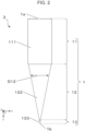
FIG. 2 is a plan view of a nozzle according to an embodiment of the present disclosure. -
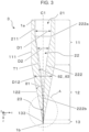
FIG. 3 is a sectional view of the nozzle taken along line I-I inFIG. 1 . -
FIG. 4 is an enlarged view of a part A of interest illustrated inFIG. 3 . -
FIG. 5 is an enlarged view of a part B of interest illustrated inFIG. 4 . -
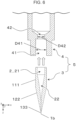
FIG. 6 is a certain exploded sectional view of a nozzle and a nozzle unit according to an embodiment of the present disclosure. -
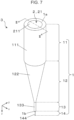
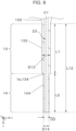
FIG. 7 is a perspective view of a nozzle according to another embodiment of the present disclosure. -
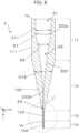
FIG. 8 is a sectional view of the nozzle taken along line II-II inFIG. 7 . -
FIG. 9 is an enlarged view of a part C of interest illustrated inFIG. 8 . - Hereinafter, several exemplary embodiments of the present disclosure are described with reference to the drawings. Note that any direction may be defined as an upper direction or a lower direction regarding a nozzle. However, for convenience, an orthogonal coordinate system xyz is defined, and a negative side in a z-direction is assumed as the lower direction. Below, a first direction indicates, for example, the z-direction in the drawings. In the present disclosure, plan view is a concept including planar transparent view.
- In an embodiment of the present disclosure, a
nozzle 3 is described with reference toFIGs. 1 to 5 . Thenozzle 3 includes abase part 1 and a through-hole 2. Thenozzle 3 contains a ceramic as a main constituent. - As illustrated in
FIGs. 1 and2 , thebase part 1 includes afirst end surface 1a and asecond end surface 1b positioned at an opposite side to thefirst end surface 1a. As a material for thebase part 1, for example, a ceramic material, such as an aluminum oxide-based sintered body, a mullite-based sintered body, a silicon carbide-based sintered body, an aluminum nitride-based sintered body, or a silicon nitride-based sintered body, or a glass-ceramic material can be used. A size of thebase part 1 in the z-direction is, for example, from 5 mm to 50 mm. A ceramic material and a glass-ceramic material are easily processible as compared with a typical metal material, and thus thenozzle 3 is easily manufacturable. - The
base part 1 further includes afirst part 11, asecond part 12, and athird part 13. Thefirst part 11 includes thefirst end surface 1a and a firstouter wall surface 111. The firstouter wall surface 11 is a cylindrical surface connected to thefirst end surface 1a, and at least a portion of the firstouter wall surface 11 is press-fitted into afix member 4. A size of thefirst part 11 in the z-direction is, for example, from 0.5 mm to 10 mm. - The
second part 12 includes a secondouter wall surface 122. The secondouter wall surface 122 is a conical surface connected to the firstouter wall surface 111 and having a first outer diameter D12 reducing as separating from thefirst end surface 1a in the z-direction (first direction). A size of thesecond part 12 in the z-direction is, for example, from 1 mm to 45 mm. A size of the first outer diameter D12 is, for example, from 0.1 mm to 5 mm. As illustrated inFIGs. 2 and3 , in an embodiment, the first outer diameter D12 reduces at a constant rate as separating from thefirst end surface 1a in the z-direction (first direction). - The
third part 13 includes thesecond end surface 1b and a thirdouter wall surface 133. The thirdouter wall surface 133 is a cylindrical surface connected to the secondouter wall surface 122 and thesecond end surface 1b and having a second outer diameter D13 equal to or less than the first outer diameter D12. A size of thethird part 13 in the z-direction is, for example, from 0.1 mm to 3 mm. A size of the second outer diameter D13 is, for example, from 0.01 mm to 2 mm. - The through-
hole 2 penetrates from thefirst end surface 1a to thesecond end surface 1b and includes a center axis C1 extending in the z-direction (first direction). The through-hole 2 may be formed by, for example, injection molding of a ceramic material or the like, or by application of punching processing to a ceramic material that has been formed in an external shape of thenozzle 3. In a case in which thenozzle 3 is used to apply fluid such as an adhesive, the fluid flows through the through-hole 2 in the positive direction of the z-axis. Pressurizing the fluid from thefirst end surface 1a side causes the fluid to pass through afirst hole part 21, asecond hole part 22, and athird hole part 23 in this order, and thus the fluid can be ejected from thesecond end surface 1b side. Here, examples of the fluid include a conductive adhesive, such as an epoxy adhesive, an acrylic adhesive, and silver paste, and solder cream. Note that in the present disclosure fluid is a concept including an object in paste form. - The through-
hole 2 further includes thefirst hole part 21, thesecond hole part 22, and thethird hole part 23. Thefirst hole part 21 has a first hole diameter D1 and is positioned at thefirst part 11. A size of the first hole diameter D1 is, for example, from 0.5 mm to 4 mm. - The
second hole part 22 has a second hole diameter D2 and is positioned from thefirst part 11 to thesecond part 12. The second hole diameter D2 reduces as separating from thefirst part 11 in the z-direction. A size of the second hole diameter D2 is, for example, from 0.5 mm to 4 mm. - The
third hole part 23 has a third hole diameter D3 and is positioned from thesecond part 12 to thethird part 13. The third hole diameter D3 is constant in the z-direction. Therefore, as compared with a case in which thethird hole part 23 has a tapered shape (the third hole diameter changes), straightness of fluid passing through thethird hole part 23 can improve. A size of the third hole diameter D3 is, for example, from 0.005 mm to 3 mm. In other words, a length of the third hole part in the z-direction is longer than the length of thethird part 13 in the z-direction. Here, being constant may include a manufacturing error. - As the length of the
third hole part 23 increases, flow channel resistance to fluid in thethird hole part 23 can be higher. An increase in flow channel resistance causes fluid to require pressure to be ejected. Therefore, adjustment of the length of thethird hole part 23 can adjust the flow channel resistance, thus reducing a possibility that fluid unintendedly drops from thesecond end surface 1b of thenozzle 3. Further, adjustment of pressure on fluid enables precise application of fluid such as an adhesive to a desired position by using thenozzle 3. Here, in a case in which viscosity of fluid is, for example, from a hundred thousand cP to five hundred thousand cP, the above-described effect is more effectively achievable. - The
third hole part 23 of thenozzle 3 is positioned from thesecond part 12 to thethird part 13. Therefore, thenozzle 3 including thethird part 13 having the second outer diameter D13 reduced in size as well as a long length in the z-direction is easily manufacturable. For example, in a case of manufacture in a manufacture method described later or the like, the length of thethird part 13 in the z-direction is easily adjustable by cutting and abrading of the secondouter wall surface 122. - The
third part 13 of thenozzle 3 has a long length in the z-direction. Therefore, in application of an adhesive to an electronic component and a mount board by using thenozzle 3, fluid such as an adhesive that flows in the positive direction of the z-axis of the through-hole 2 is precisely applicable to a desired position. - As illustrated in
FIG. 3 , the first hole diameter D1 may be constant in the z-direction. With such a configuration, a length by which thenozzle 3 press-fitted into thefix member 4 described later protrudes in the z-direction (seeFIG. 6 ) is adjustable through cutting and abrading of the first end surface a1 in such a manner that a second opening part diameter D42 of asecond opening part 42 and the first hole diameter D1 match one another. Accordingly, various types ofnozzles 3 are easily manufacturable in accordance with user needs. - Note that, unlikely to an embodiment illustrated in
FIG. 3 , thefirst hole part 21 and thesecond hole part 22 may be continue to and flush with one another. In this case, in sectional view passing through the center axis C1 and in parallel to the z-direction (for example, in the xz plane or the yz plane), when a secondinner wall surface 222 described later forms a straight line with an inclination with respect to the center axis C1, this inclination may be the same as an inclination of a firstinner wall surface 211 with respect to the center axis C1. - As illustrated in
FIG. 3 , thefirst hole part 21 includes the firstinner wall surface 211 connected to thefirst end surface 1a. Thesecond hole part 22 includes the secondinner wall surface 222 connected to the firstinner wall surface 211. Thethird hole part 23 includes a thirdinner wall surface 233 connected to the secondinner wall surface 222. The secondinner wall surface 222 includes afirst end part 222a connected to the firstinner wall surface 211 and asecond end part 222b connected to the thirdinner wall surface 233. In sectional view passing through the center axis C1 and in parallel to the z-direction (for example, in the xy plane), assuming that a straight line coupling thefirst end part 222a to thesecond end part 222b is a first virtual line T1, an inclination θ1 of the secondouter wall surface 122 with respect to the center axis C1 may be equal to or more than an inclination θ2 of the first virtual line T1 with respect to the center axis C1. That is, a thickness of at least a portion of thesecond part 12 of the nozzle 3 (a distance between the secondinner wall surface 222 and the second outer wall surface 122) is not necessarily constant. With the configuration as described above, thenozzle 3 can have less possibility of getting damaged when the second part 12 (second outer wall surface 122) is gripped to press-fit thenozzle 3 into afirst opening part 41 of thefix member 4 described later. - Surface roughness Ra1 of the second
inner wall surface 222 may be larger than surface roughness Ra2 of the thirdinner wall surface 233. In a case in which the surface roughness Ra1 of the secondinner wall surface 222 is the same as the surface roughness Ra2 of the thirdinner wall surface 233, since the third hole diameter D3 is equal to or less than the second hole diameter D2, flow channel resistance to fluid is larger in thethird hole part 23 than in thesecond hole part 22. Therefore, the surface roughness Ra1 of the secondinner wall surface 222 being larger than the surface roughness Ra2 of the thirdinner wall surface 233 can make the flow channel resistance of fluid in thethird hole part 23 be closer to the flow channel resistance in thesecond hole part 22. Thereby, upon application of pressure on fluid, an ejection timing of fluid can be less likely to deviate from expectation. Accordingly, application diameter of fluid ejected from thesecond end surface 1b can be less likely to vary. Such a configuration can reduce a possibility that fluid flowing the through-hole 2 unintendedly drops from thesecond end surface 1b of thenozzle 3. - The
base part 1 may contain zirconia as a main constituent. Here, a "main constituent" in the present disclosure may be any constituent with at least a highest content rate, and indicates, for example, a constituent with a content rate of 90% or more. Zirconia has higher strength than aluminum oxide or the like. Therefore, as illustrated inFIG. 5 , thethird part 13 can have a longer length in the z-direction with the second outer diameter D13 reduced in size. In addition, thethird part 13 of thenozzle 3 can have a smaller thickness (a distance between the thirdinner wall surface 233 and the third outer wall surface 133). Since zirconia excels in wear resistance and chemical resistance as compared with aluminum oxide or the like, thenozzle 3 can have less possibility of getting worn or damaged. - As illustrated in
FIG. 3 , in sectional view passing through the center axis C1 and in parallel to the z-direction, the secondinner wall surface 222 may have an arc shape. In an embodiment, the secondinner wall surface 222 has an arc shape protruding to the center axis C1 side. Such a configuration can reduce flow channel resistance to fluid passing through thesecond hole part 22. Therefore, upon application of pressure on fluid, an ejection timing of fluid can be less likely to deviate from expectation. Accordingly, application diameter of fluid ejected from thesecond end surface 1b can be less likely to vary. - As illustrated in
FIG. 3 , in sectional view passing through the center axis C1 and in parallel to the z-direction, an inclination θ3 of the secondinner wall surface 222 with respect to the center axis C1 may be from 10 to 20°. Such a configuration can facilitate, in manufacture of thenozzle 3 in the manufacture method described later, removal of a formed body of thenozzle 3 formed thorough injection molding, from a formation mold. - As illustrated in
FIG. 4 , in sectional view passing through the center axis C1 and in parallel to the z-direction, the secondouter wall surface 122 and the thirdouter wall surface 133 may be connected to one another with afirst connection part 123 in an arc shape interposed therebetween. With such a configuration, stress concentrates at thefirst connection part 123, and thenozzle 3 can have less possibility of getting damaged. - As illustrated in
FIGs. 4 and5 , assuming that a dimension of thethird part 13 in the z-direction is L1 [mm], the second outer diameter is D13 [mm], and the third hole diameter is D3 [mm], the following formula (1) may be satisfied. This configuration can further reduce a possibility of thethird part 13 bending from thesecond part 12. - Note that in this case a thickness of the third part 13 (that is, D13 - D3) may be 0.04 [mm] or more. This configuration can reduce, in processing or manufacture of the
nozzle 3, a possibility of thethird part 13 getting damaged.
- In other embodiments of the present disclosure, the
nozzle 3 is described with reference toFIGs. 7 to 9 . Note that, among configurations of the other embodiments, only a configuration different from the configuration in the above-described embodiment is described below, and description of the rest of the configurations will be omitted with reference signs as those in the above-described embodiment denoted thereto. - In an embodiment, the
base part 1 may further include afourth part 14 connected to thesecond end surface 1b. Thefourth part 14 may include a fourthouter wall surface 144 in a cylindrical shape having a third outer diameter D14 smaller than the second outer diameter D13. Thethird hole part 23 further extends from thethird part 13 to thefourth part 14. That is, thefourth part 14 with the smaller outer diameter may be connected to a tip of thethird part 13. With this configuration, even in a case in which a tip end of thenozzle 3 has a reduced diameter (third outer diameter D14) as well as an increased length, a tip-end portion of the nozzle 3 (here, indicating a portion combining thethird part 13 and the fourth part 14) can have less possibility of getting damaged. Such anozzle 3 enables application of fluid to a narrower range. - In an embodiment, as illustrated in
FIG. 9 , the third hole diameter D3 of thethird hole part 23 in thefourth part 14 may be the same as or different from the third hole diameter D3 of thethird hole part 23 in the third part. - As illustrated in
FIG. 9 , in sectional view passing through the center axis C1 and in parallel to the z-direction (for example, in the xz plane or the yz plane), the thirdouter wall surface 133 and the fourthouter wall surface 144 may be connected to one another with asecond connection part 134 in an arc shape interposed therebetween. This configuration can reduce a sharp change in the dimension from the second outer diameter D13 to the third outer diameter D14, and thus thefourth part 14 can have improved strength. Further, even when an object hits thefourth part 14 from outside, thefourth part 14 can have less possibility of bending from thethird part 13. In addition, when fluid is flowed into thenozzle 3, thethird part 13 and thefourth part 14 can have less possibility of getting damaged by fluid pressure. In the configuration described above, thesecond connection part 134 may match thesecond end surface 1b. - More specifically, assuming that a dimension of the
fourth part 14 in the z-direction is L2 [mm], the third hole diameter D3 is D3 [mm], and the third outer diameter D14 is D14 [mm], the following formula (2) may be satisfied. Note that in this case a thickness of the fourth part 14 (that is, D14 - D3) may be 0.04 [mm] or more.
- Assuming that a combined dimension of the
fourth part 14 and thethird part 13 in the z-direction is L12 [mm], and the second outer diameter D13 is D13 [mm], the following formula (3) may be satisfied. Note that in this case a thickness of the third part 13 (that is, D13 - D3) may be 0.04 [mm] or more.
- Here, an example of a method for manufacturing the
nozzle 3 is described. In the example described, a ceramic containing zirconia as a main constituent (a zirconia-based ceramic) is used as a constituent material for thenozzle 3. Note that the present disclosure is not limited to the following embodiment. - (1) First, a formation material to form a formed body is prepared. The formed body is an original form of the
nozzle 3. Specifically, the formation material is prepared by sufficient mixing and grinding of mixed powder of zirconium oxide powder and yttrium oxide powder by a ball mill or the like, and then adding of a binder to the grinded object to be mixed. The mixed powder may be mixture of zirconium oxide powder of 85 to 99 mass% and yttrium oxide powder of 1 to 15 mass%, particularly, mixture of zirconium oxide powder of 90 to 98 mass% and yttrium oxide powder of 2 to 10 mass%. In the zirconium oxide powder, purity of zirconium oxide can be 95% or more, particularly, 98% or more. - (2) Next, the prepared formation material is used to obtain the formed body including the through
hole 2. Specifically, the formation material is filled in a cavity of a formation mold to perform injection molding, and thus the formed body is obtained. The formation mold with the cavity includes a structure for forming the through-hole 2. Note that a method for obtaining the formed body is not limited to the injection molding described above, but a method, for example, press forming, slipcasting, cold isostatic press forming, or extrusion forming may be adopted. - (3) Next, the obtained formed body is fired to obtain a sintered body. Specifically, the obtained formed body is put in a debinder furnace at 500 to 600°C for 2 to 10 hours to perform debinding, and then the debinded formed body is fired in oxygen atmosphere at 1300 to 1500°C for 0.5 to 3 hours, and thus the sintered body is obtained.
- (4) Next, an inner circumferential surface of the through-
hole 2 of the obtained sintered body is applied with abrading processing or the like to form the thirdinner wall surface 233. Specifically, an abrading material is pressed against the through-hole 2 while thenozzle 3 is rotated with the center axis C1 serving as a rotational axis, and thus the thirdinner wall surface 233 is formed. The same as and/or similarly to the thirdinner wall surface 233, the firstinner wall surface 211 and the secondinner wall surface 222 may also be applied with abrading processing or the like. At this time, grinding oil can be used to perform abrading while suppressing an increase in surface roughness. - (5) Next, cutting and abrading processing or the like is applied to an external shape of the obtained sintered body to form the first
outer wall surface 111, the secondouter wall surface 122, and the thirdouter wall surface 133. In this manner, thenozzle 3 is manufacturable. - As illustrated in
FIG. 6 , anozzle unit 5 includes thenozzle 3 and thefix member 4. Thefix member 4 includes thefirst opening part 41. In thefirst opening part 41, at least a portion of thefirst part 11 of thenozzle 3 is press-fitted. - Examples of a material for the
fix member 4 include a metal material. Thefirst opening part 41 may have a first opening part diameter D41. Thefix member 4 may include thesecond opening part 42 connected to thefirst opening part 41. Thesecond opening part 42 has the second opening part diameter D42. In this case, the second opening part diameter D42 may be equal to or less than the first opening part diameter D41. With this configuration, thesecond opening part 42 serves as a guide to fix thenozzle 3 press-fitted into thefirst opening part 41 to a desired position. The second opening part diameter D42 may be the same as the first hole diameter D1 of thenozzle 3. - In a case in which the
nozzle unit 5 is used to apply fluid such as a conductive adhesive to an application target object, the fluid is pressurized inside a pressure device (not illustrated) to which thefix member 4 is attached, and this pressure pushes out the fluid into the through-hole 2 of thenozzle 3 through thesecond opening part 42. The fluid is ejected from thesecond end surface 1b of thenozzle 3 through the through-hole 2, thus being applied to the application target object. - With such a configuration, a nozzle with a portion from which fluid is ejected and having an elongated shape is easily manufacturable.
- Such a configuration can further provide a nozzle, for example, capable of applying fluid also to a narrow range, such as between electronic components.
- Note that various combinations of feature parts in an embodiment is not limited to the examples of the embodiments described above. The respective embodiments can be combined together.
- The present disclosure is applicable to a nozzle and a nozzle unit.
-
- 1 base part
- 1a first end surface
- 1b second end surface
- 11 first part
- 111 first outer wall surface
- 12 second part
- 122 second outer wall surface
- 123 first connection part
- 13 third part
- 133 third outer wall surface
- 134 second connection part
- 14 fourth part
- 144 fourth outer wall surface
- 2 through-hole
- 21 first hole part
- 211 first inner wall surface
- 22 second hole part
- 222 second inner wall surface
- 222a first end part
- 222b second end part
- 23 third hole part
- 233 third inner wall surface
- C1 center axis
- T1 first virtual line
- D1 first hole diameter
- D2 second hole diameter
- D3 third hole diameter
- D12 first outer diameter
- D13 second outer diameter
- D14 third outer diameter
- D41 first opening part diameter
- D42 second opening part diameter
- L1 third part dimension in first direction
- L2 fourth part dimension in first direction
- L12 fourth part and third part combined dimension in first direction
- θ1 first virtual line inclination
- θ2 second outer wall surface inclination
- θ3 second inner wall surface inclination
- 3 nozzle
- 4 fix member
- 41 first opening part
- 42 second opening part
- 5 nozzle unit
Claims (15)
- A nozzle comprising:a base part comprising a first end surface and a second end surface positioned at an opposite side to the first end surface, and containing a ceramic as a main constituent; anda through-hole penetrating from the first end surface to the second end surface and comprising a center axis extending in a first direction, whereinthe base part further comprises:a first part comprising the first end surface and a first outer wall surface in a cylindrical shape, wherein the first outer wall surface is connected to the first end surface, and at least a portion of the first outer wall surface is configured to be press-fitted into a fix member;a second part comprising a second outer wall surface in a conical shape, wherein the second outer wall surface is connected to the first outer wall surface and has a first outer diameter reducing as separating from the first end surface in the first direction; anda third part comprising the second end surface and a third outer wall surface in a cylindrical shape, wherein the third outer wall surface is connected to the second outer wall surface and the second end surface and has a second outer diameter equal to or less than the first outer diameter,the through-hole comprises:a first hole part having a first hole diameter and positioned at the first part;a second hole part having a second hole diameter and positioned from the first part to the second part; anda third hole part having a third hole diameter and positioned from the second part to the third part,the second hole diameter reduces as separating from the first part in the first direction, andthe third hole diameter is constant in the first direction.
- The nozzle according to claim 1, wherein the first hole diameter is constant in the first direction.
- The nozzle according to claim 1 or 2, wherein the first hole part comprises a first inner wall surface connected to the first end surface,the second hole part comprises a second inner wall surface connected to the first inner wall surface,the third hole part comprises a third inner wall surface connected to the second inner wall surface,the second inner wall surface comprises a first end part connected to the first inner wall surface and a second end part connected to the third inner wall surface, andin sectional view passing through the center axis and in parallel to the first direction, when a straight line coupling the first end part to the second end part is a first virtual line, an inclination θ1 of the first virtual line with respect to the center axis is equal to or less than an inclination θ2 of the second outer wall surface with respect to the center axis.
- The nozzle according to claim 3, wherein surface roughness Ra1 of the second inner wall surface is larger than surface roughness Ra2 of the third inner wall surface.
- The nozzle according to any one of claims 1 to 4, wherein the base part contains zirconia as a main constituent.
- The nozzle according to claim 3 or 4, wherein, in sectional view passing through the center axis and in parallel to the first direction, the second inner wall surface has an arc shape.
- The nozzle according to any one of claims 3, 4, and 6, wherein, in sectional view passing through the center axis and in parallel to the first direction, an inclination θ3 of the second inner wall surface with respect to the center axis is from 10 to 20°.
- The nozzle according to any one of claims 1 to 7, wherein, in sectional view passing through the center axis and in parallel to the first direction, the second outer wall surface and the third outer wall surface are connected to one another with a first connection part in an arc shape interposed therebetween.
- The nozzle according to any one of claims 1 to 8, wherein when a dimension of the third part in the first direction is L1,the third hole diameter is D3, andthe second outer diameter is D13,L1 ≤ 378 × [D143 - (D34/D14)] is satisfied.
- The nozzle according to any one of claims 1 to 9, wherein the base part further comprises a fourth part connected to the second end surface,the fourth part comprises a fourth outer wall surface in a cylindrical shape having a third outer diameter smaller than the second outer diameter, andthe third hole part further extends from the third part to the fourth part.
- The nozzle according to claim 10, wherein, in sectional view passing through the center axis and in parallel to the first direction, the third outer wall surface and the fourth outer wall surface are connected to one another with a second connection part in an arc shape interposed therebetween.
- The nozzle according to claim 10 or 11, wherein a dimension of the fourth part in the first direction is equal to or less than half a combined dimension of the fourth part and the third part in the first direction.
- The nozzle according to any one of claims 10 to 12, wherein when a dimension of the fourth part in the first direction is L2,the third hole diameter is D3, andthe third outer diameter is D14,L2 ≤ 378 × [D143 - (D34/D14)] is satisfied.
- The nozzle according to any one of claims 10 to 13, wherein when a combined dimension of the fourth part and the third part in the first direction is L12, andthe second outer diameter is D13,L12 ≤ 378 × [D133 - (D34/D13)] is satisfied.
- A nozzle unit comprising:the nozzle according to any one of claims 1 to 14; anda fix member comprising a first opening part into which the first part is configured to be press-fitted.
Applications Claiming Priority (2)
| Application Number | Priority Date | Filing Date | Title |
|---|---|---|---|
| JP2022102811 | 2022-06-27 | ||
| PCT/JP2023/022790 WO2024004765A1 (en) | 2022-06-27 | 2023-06-20 | Nozzle and nozzle unit |
Publications (1)
| Publication Number | Publication Date |
|---|---|
| EP4545184A1 true EP4545184A1 (en) | 2025-04-30 |
Family
ID=89382228
Family Applications (1)
| Application Number | Title | Priority Date | Filing Date |
|---|---|---|---|
| EP23831211.0A Withdrawn EP4545184A1 (en) | 2022-06-27 | 2023-06-20 | Nozzle and nozzle unit |
Country Status (4)
| Country | Link |
|---|---|
| EP (1) | EP4545184A1 (en) |
| JP (2) | JP7614457B2 (en) |
| CN (1) | CN119403628A (en) |
| WO (1) | WO2024004765A1 (en) |
Family Cites Families (12)
| Publication number | Priority date | Publication date | Assignee | Title |
|---|---|---|---|---|
| DE3234638C1 (en) | 1982-09-18 | 1991-01-03 | Diehl Gmbh & Co | Sealing for differential pressure piston combustion chamber systems of barrel weapons |
| JPH0651319B2 (en) * | 1989-10-20 | 1994-07-06 | 凸版印刷株式会社 | Injection molding nozzle and injection molding method |
| JPH05200328A (en) * | 1992-01-23 | 1993-08-10 | Riken Corp | Fuel injector nozzle |
| JP2000262944A (en) | 1999-03-18 | 2000-09-26 | Matsushita Electric Ind Co Ltd | Phosphor coating nozzle and method of forming phosphor layer |
| JP3958040B2 (en) * | 2001-12-17 | 2007-08-15 | 京セラ株式会社 | Manufacturing method of ceramic nozzle |
| JP2003340318A (en) | 2002-05-24 | 2003-12-02 | Kyocera Corp | Nozzle made of ceramic and manufacturing method therefor |
| JP4987557B2 (en) | 2007-05-07 | 2012-07-25 | 株式会社アルバック | Liquid crystal material discharge apparatus and nozzle manufacturing method |
| JP4785064B2 (en) | 2007-06-13 | 2011-10-05 | 武蔵エンジニアリング株式会社 | Manufacturing method of nozzle unit for minute dispensing and precision application of functional liquid materials |
| JP2007292081A (en) | 2007-08-17 | 2007-11-08 | Hitachi Ltd | Fuel injection valve |
| JP2019058886A (en) | 2017-09-28 | 2019-04-18 | 日本電波工業株式会社 | Nozzle unit and method for manufacturing the same |
| CN209829298U (en) | 2019-04-12 | 2019-12-24 | 东莞市西陶精密陶瓷有限公司 | Ceramic nozzle |
| CN112693734B (en) | 2020-12-22 | 2021-10-08 | 爱索尔(广州)包装有限公司 | Quantitative liquid outlet assembly for watery paste and packaging container |
-
2023
- 2023-06-20 WO PCT/JP2023/022790 patent/WO2024004765A1/en not_active Ceased
- 2023-06-20 EP EP23831211.0A patent/EP4545184A1/en not_active Withdrawn
- 2023-06-20 CN CN202380047990.1A patent/CN119403628A/en not_active Withdrawn
- 2023-06-20 JP JP2024530725A patent/JP7614457B2/en active Active
-
2024
- 2024-12-26 JP JP2024229578A patent/JP2025031939A/en active Pending
Also Published As
| Publication number | Publication date |
|---|---|
| CN119403628A (en) | 2025-02-07 |
| JP7614457B2 (en) | 2025-01-15 |
| WO2024004765A1 (en) | 2024-01-04 |
| JPWO2024004765A1 (en) | 2024-01-04 |
| JP2025031939A (en) | 2025-03-07 |
Similar Documents
| Publication | Publication Date | Title |
|---|---|---|
| JP5175650B2 (en) | Porcelain capable of anodic bonding and composition for porcelain | |
| US8971008B2 (en) | Electrostatic chuck | |
| US10790091B2 (en) | Electronic component having depression on surface | |
| KR102450795B1 (en) | fine drill | |
| WO2018094162A4 (en) | Filling materials and methods of filling through holes of a substrate | |
| EP4545184A1 (en) | Nozzle and nozzle unit | |
| US9788424B2 (en) | Wiring substrate, electronic device, and electronic module | |
| JP2011223025A (en) | Ceramic core and manufacturing method thereof and chip-shaped electronic components using the same | |
| JP2013033200A (en) | Ferrule, optical fiber holding component, optical fiber pigtail, and optical receptacle | |
| JPH0672050B2 (en) | Bonding capillaries and optical connector parts | |
| WO2025205518A1 (en) | Nozzle, nozzle unit, and coating device | |
| KR102111584B1 (en) | Capillary For Wire Bonding And Method Of Fabricating The Same | |
| US20010032887A1 (en) | Precision dispensing tip and method | |
| WO2021010073A1 (en) | Electronic-component bonding nozzle | |
| JP6835540B2 (en) | Ceramic wiring board, probe board and probe card | |
| JP2005317591A (en) | Ceramic core, manufacturing method thereof, and chip-shaped electronic component using the same | |
| JP2003145008A (en) | Discharge device and discharge method | |
| JPS6276527A (en) | Wire bonding capillary | |
| US8080737B2 (en) | Ceramic substrate, method of manufacturing the same, and electrical device using the same | |
| JP2774783B2 (en) | Optical connector parts | |
| CN114080674A (en) | Terminal structure, package, and method for manufacturing terminal structure | |
| JP5253616B2 (en) | Ferrule and optical fiber fixture using the same | |
| CN112585743A (en) | Wiring substrate, package for housing electronic component, and electronic device | |
| JP2009239066A (en) | Ceramic substrate, and manufacturing method therefor | |
| US12005536B2 (en) | Method of surface texturing for a writing instrument tip |
Legal Events
| Date | Code | Title | Description |
|---|---|---|---|
| STAA | Information on the status of an ep patent application or granted ep patent |
Free format text: STATUS: THE INTERNATIONAL PUBLICATION HAS BEEN MADE |
|
| PUAI | Public reference made under article 153(3) epc to a published international application that has entered the european phase |
Free format text: ORIGINAL CODE: 0009012 |
|
| STAA | Information on the status of an ep patent application or granted ep patent |
Free format text: STATUS: REQUEST FOR EXAMINATION WAS MADE |
|
| 17P | Request for examination filed |
Effective date: 20241218 |
|
| AK | Designated contracting states |
Kind code of ref document: A1 Designated state(s): AL AT BE BG CH CY CZ DE DK EE ES FI FR GB GR HR HU IE IS IT LI LT LU LV MC ME MK MT NL NO PL PT RO RS SE SI SK SM TR |
|
| STAA | Information on the status of an ep patent application or granted ep patent |
Free format text: STATUS: THE APPLICATION HAS BEEN WITHDRAWN |
|
| 18W | Application withdrawn |
Effective date: 20250804 |