EP4545103A2 - Flugzeugbordküche mit integriertem luftionisator - Google Patents
Flugzeugbordküche mit integriertem luftionisator Download PDFInfo
- Publication number
- EP4545103A2 EP4545103A2 EP24209243.5A EP24209243A EP4545103A2 EP 4545103 A2 EP4545103 A2 EP 4545103A2 EP 24209243 A EP24209243 A EP 24209243A EP 4545103 A2 EP4545103 A2 EP 4545103A2
- Authority
- EP
- European Patent Office
- Prior art keywords
- galley
- voltage
- control unit
- air
- ion
- Prior art date
- Legal status (The legal status is an assumption and is not a legal conclusion. Google has not performed a legal analysis and makes no representation as to the accuracy of the status listed.)
- Pending
Links
Images



Classifications
-
- B—PERFORMING OPERATIONS; TRANSPORTING
- B64—AIRCRAFT; AVIATION; COSMONAUTICS
- B64D—EQUIPMENT FOR FITTING IN OR TO AIRCRAFT; FLIGHT SUITS; PARACHUTES; ARRANGEMENT OR MOUNTING OF POWER PLANTS OR PROPULSION TRANSMISSIONS IN AIRCRAFT
- B64D11/00—Passenger or crew accommodation; Flight-deck installations not otherwise provided for
- B64D11/04—Galleys
-
- A—HUMAN NECESSITIES
- A61—MEDICAL OR VETERINARY SCIENCE; HYGIENE
- A61L—METHODS OR APPARATUS FOR STERILISING MATERIALS OR OBJECTS IN GENERAL; DISINFECTION, STERILISATION OR DEODORISATION OF AIR; CHEMICAL ASPECTS OF BANDAGES, DRESSINGS, ABSORBENT PADS OR SURGICAL ARTICLES; MATERIALS FOR BANDAGES, DRESSINGS, ABSORBENT PADS OR SURGICAL ARTICLES
- A61L9/00—Disinfection, sterilisation or deodorisation of air
- A61L9/16—Disinfection, sterilisation or deodorisation of air using physical phenomena
- A61L9/22—Ionisation
-
- B—PERFORMING OPERATIONS; TRANSPORTING
- B64—AIRCRAFT; AVIATION; COSMONAUTICS
- B64D—EQUIPMENT FOR FITTING IN OR TO AIRCRAFT; FLIGHT SUITS; PARACHUTES; ARRANGEMENT OR MOUNTING OF POWER PLANTS OR PROPULSION TRANSMISSIONS IN AIRCRAFT
- B64D13/00—Arrangements or adaptations of air-treatment apparatus for aircraft crew or passengers, or freight space
- B64D13/06—Arrangements or adaptations of air-treatment apparatus for aircraft crew or passengers, or freight space the air being conditioned
- B64D2013/0603—Environmental Control Systems
- B64D2013/067—Environmental Control Systems with air ionizers
-
- F—MECHANICAL ENGINEERING; LIGHTING; HEATING; WEAPONS; BLASTING
- F24—HEATING; RANGES; VENTILATING
- F24F—AIR-CONDITIONING; AIR-HUMIDIFICATION; VENTILATION; USE OF AIR CURRENTS FOR SCREENING
- F24F8/00—Treatment, e.g. purification, of air supplied to human living or working spaces otherwise than by heating, cooling, humidifying or drying
- F24F8/30—Treatment, e.g. purification, of air supplied to human living or working spaces otherwise than by heating, cooling, humidifying or drying by ionisation
Definitions
- the present disclosure generally relates to systems for managing air quality in an aircraft, and more specifically, to using air ionizers in an aircraft.
- Circulation of air within an enclosed space may include circulation of harmful pathogens (e.g., viruses, bacteria, etc.) and undesirable odors.
- pathogens e.g., viruses, bacteria, etc.
- HEPA high efficiency particulate air
- air filters are placed at central locations and therefore may not have continuous effectiveness within the enclosed space.
- more effective air filters, such as HEPA filters come with an increased cost both in terms of the filter itself as well as the energy used to force air through the air filter.
- air filters, including HEPA filters tend to not remove odors from the air within the enclosed space.
- the aircraft galley includes an air duct including an air inlet and an air outlet. The air outlet extends into the aircraft galley.
- the aircraft galley includes an ion emitter coupled to the air outlet.
- the aircraft galley includes a control unit electronically coupled to the ion emitter. The control unit is configured to control an ion output of the ion emitter.
- the ion emitter is configured to be in an air flow passing through the air outlet. In various embodiments, the ion emitter is perpendicular to the air flow passing through the air outlet. In various embodiments, the air outlet includes an opening having an outer circumference and the ion emitter is coupled to the opening and extends inward from the outer circumference. In various embodiments, the aircraft galley further includes a plurality of ion emitters arranged around the outer circumference of the opening. In various embodiments, each of the plurality of ion emitters is perpendicular to a flow of air passing through the opening.
- the air inlet extends to an exterior of the aircraft galley to provide the air duct with air from outside of the aircraft galley.
- the control unit includes a voltage input having a first voltage and a voltage output having a second voltage that is greater than the first voltage, the voltage output being coupled to the ion emitter.
- the aircraft includes a galley and an air duct extending into the galley.
- the air duct including an air outlet disposed within the galley.
- the aircraft includes an ion emitter coupled to the air outlet.
- the aircraft includes a control unit electronically coupled to the ion emitter, the control unit configured to control an ion generation of the ion emitter.
- the ion emitter is configured to be in an air flow passing through the air outlet and into the galley. In various embodiments, the ion emitter is perpendicular to the air flow passing through the air outlet. In various embodiments, the air outlet includes an opening having an outer circumference and the ion emitter is coupled to the opening and extends inward from the outer circumference. In various embodiments, the aircraft further includes a plurality of ion emitters arranged around the outer circumference of the opening. In various embodiments, each of the plurality of ion emitters is perpendicular to a flow of air passing through the opening.
- the galley further includes a wall disposed between the control unit and the galley.
- the control unit includes a voltage input having a first voltage and a voltage output having a second voltage that is greater than the first voltage, the voltage output being coupled to the ion emitter.
- the system includes a first ion emitter coupled to a first air outlet inside a first galley, a first control unit electronically coupled to the first ion emitter, a graphical user interface, a processor electronically coupled to the first control unit, and a memory operatively coupled to the processor.
- the memory includes instructions stored thereon that, when executed by the processor, cause the processor to receive an input from the graphical user interface and send a first signal to the first control unit to adjust a first voltage to the first ion emitter in response to the input.
- the system further includes a second ion emitter coupled to a second air outlet inside a second galley and a second control unit electronically coupled to the second ion emitter.
- the instructions when executed by the processor, further cause the processor to send a second signal to the second control unit to adjust a second voltage of the second ion emitter in response to the input.
- the instructions when executed by the processor, further cause the processor to receive a second input from the graphical user interface indicating a change in settings for the second galley and sending a third signal to the second control unit to adjust the second voltage of the second ion emitter in response to the second input, the second voltage being different than the first voltage.
- the second voltage is the same as the first voltage.
- the instructions when executed by the processor, further cause the processor to send a third signal to the first control unit to decrease the first voltage of the first ion emitter in response to a third input and send a fourth signal to the second control unit to increase the second voltage of the second ion emitter in response to the third input.
- the first control unit is disposed in the first galley.
- any reference to singular includes plural embodiments, and any reference to more than one component or step may include a singular embodiment or step.
- any reference to attached, fixed, connected, or the like may include permanent, removable, temporary, partial, full or any other possible attachment option.
- any reference to without contact (or similar phrases) may also include reduced contact or minimal contact. It should also be understood that unless specifically stated otherwise, references to "a,” “an” or “the” may include one or more than one and that reference to an item in the singular may also include the item in the plural. Further, all ranges may include upper and lower values and all ranges and ratio limits disclosed herein may be combined.
- the air ionizer includes a control unit and one or more ion emitters.
- the ion emitters may be coupled to an air outlet located within the galley.
- the ion emitters may be arranged perpendicular to a flow of air through the air outlet.
- the ion emitters may be located radially around the air outlet.
- the ion emitters are positioned to direct ions toward the passenger space proximate the galley.
- the integrated air ionizer provides a high density of ions into the passenger area to combat chemicals and compounds that may cause malodor within the galley.
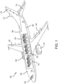
- aircraft 100 also includes various cabin sections, including, for example, a first cabin section 118, a second cabin section 120, a third cabin section 122, and a pilot cabin 124.
- aircraft 100 may include a front galley 126 and/or a rear galley 128.
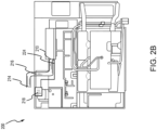
- FIGS. 2A and 2B a galley 200 is illustrated, in accordance with various embodiments.
- the galley 200 may be an example of the front galley 126 or the rear galley 128 of FIG. 1 .
- FIG. 2A illustrates a front view of the galley 200.
- FIG. 2B illustrates a rear view of the galley 200.
- the galley 200 may include a plurality of stowage bins 202, a preparation area 204, a trash receptacle 206, one or more galley carts 208, an air outlet 210, ion emitters 212, an air inlet 214, an air duct 216 coupled to air inlet 214 and air outlet 210, and a control unit 218.
- the ion emitters 212 may be mounted on a side wall proximate the preparation area 204, adjacent the air outlet 210, within the air outlet 210, or at an outlet of the air outlet 210.
- the ion emitters 212 may be mounted within the air outlet 210.
- the ion emitters 212 generate ionized air particles, including negative ions 220 and positive ions 222, that are spread throughout the galley 200 by air flow from the air outlet 210.
- the ion emitters 212, and more specifically, the positive ions 222 may neutralize pathogens (e.g., bacteria, viruses, molds, dust, etc.) and/or malodor (i.e., unpleasant smells) that are airborne and on surfaces. Pathogens and malodor may be generated and/or spread by the plurality of stowage bins 202, the preparation area 204, the trash receptacle 206, and the one or more galley carts 208, among other locations.
- pathogens e.g., bacteria, viruses, molds, dust, etc.
- malodor i.e., unpleasant smells
- the ion emitters 212 may be placed adjacent the air outlet 210 so that the ion emitters 212 ionizes the air exiting the air outlet 210.
- ions created by the ion emitters 212 such as the negative ions 220 and the positive ions 222, have an active life span of about 30 seconds to about 75 seconds, and more specifically, about 45 seconds to about 60 seconds. Accordingly, locating the ion emitters 212 adjacent the air outlet 210 improves the efficacy of the negative ions 220 and the positive ions 222 as compared to placing an air ionizer within ductwork of an air handling system or adjacent an air filter within the air handling system.
- the ion emitters 212 may be placed inside the air outlet 210, and more specifically, within the ductwork behind the air outlet 210 and immediately adjacent the air outlet 210. In various embodiments, the ion emitters 212 may be incorporated into the air outlet 210 so the ion emitters 212 and the air outlet 210 operate as a single unit to ionize and disperse air throughout the galley 200.
- the galley 200 further includes the control unit 218 that is operatively and electrically coupled to the ion emitters 212 by one or more wires 224.
- the control unit 218 controls each of the ion emitters 212 by adjusting a voltage, a current, a timing, and/or other parameters to increase or decrease a number of ions produced by each of the ion emitters 212.
- increasing a voltage and/or a current to each of the ion emitters 212 increases the number of ions produced by the ion emitters 212.
- decreasing the voltage and/or the current to each of the ion emitters 212 decreases the number of ions produced by the ion emitters 212.
- control unit 218 may control each of the ion emitters 212 individually and/or as all together. In various embodiments, the control unit 218 may step up a received alternating current (AC) or a direct current (DC) voltage to a high voltage for use by the ion emitters 212. In various embodiments, the control unit 218 may be connected to a 115 V AC power source. In various embodiments, the control unit 218 may be connected to a 28 V DC power source. In various embodiments, the control unit 218 may output about 2.5 KV to about 12.5 KV, and more specifically, about 5 KV to about 10 KV.
- AC alternating current
- DC direct current
- control unit 218 may comprise one or more processors configured to implement various logical operations in response to execution of instructions, for example, instructions stored on a non-transitory, tangible, computer-readable medium.
- the one or more processors can be a general-purpose processor, a microprocessor, a microcontroller, a digital signal processor (DSP), an application specific integrated circuit (ASIC), a field programmable gate array (FPGA) or other programmable logic device, discrete or transistor logic, discrete hardware components, or any combination thereof.
- the control unit 218 may further comprise memory to store data, executable instructions, system program instructions, and/or controller instructions to implement the control logic of the control unit 218.
- FIGS. 3A and 3B a galley 300 is illustrated, in accordance with various embodiments.
- the galley 300 may be an example of the front galley 126 or the rear galley 128 of FIG. 1 .
- FIG. 3A illustrates a front view of the galley 300.
- FIG. 3B illustrates a rear view of the galley 300.
- the galley 300 may include a plurality of stowage bins 302, a preparation area 304, a trash receptacle 306, one or more galley carts 308, an air outlet 310, one or more ion emitters 312, an air inlet 314, an air duct 316 coupled to air inlet 314 and air outlet 310, and a control unit 318.
- the ion emitters 312 may be mounted on a back wall proximate the preparation area 304, adjacent the air outlet 310, within the air outlet 310, or at an outlet of the air outlet 310.
- the ion emitters 312 may be mounted within the air outlet 310.
- the ion emitters 312 generate ionized air particles, including negative ions 320 and positive ions 322, that are spread throughout the galley 300 by air flow from the air outlet 310.
- the ion emitters 312, and more specifically, the positive ions 322 may neutralize pathogens (e.g., bacteria, viruses, molds, dust, etc.) and/or malodor (i.e., unpleasant smells) that are airborne and on surfaces.
- Pathogens and malodor may be generated and/or spread by the plurality of stowage bins 302, the preparation area 304, the trash receptacle 306, and the one or more galley carts 308, among other locations.
- Pathogens and malodor may be airborne and/or settle on surfaces within the galley 300, including the plurality of stowage bins 302, the preparation area 304, the trash receptacle 306, and the one or more galley carts 308, among others.
- the ion emitters 312 may be placed adjacent the air outlet 310 so that the ion emitters 312 ionizes the air exiting the air outlet 310.
- ions created by the ion emitters 312, such as the negative ions 320 and the positive ions 322 have an active life span of about 30 seconds to about 75 seconds, and more specifically, about 45 seconds to about 60 seconds. Accordingly, locating the ion emitters 312 adjacent the air outlet 310 improves the efficacy of the negative ions 320 and the positive ions 322 as compared to placing an air ionizer within ductwork of an air handling system or adjacent an air filter within the air handling system.
- the ion emitters 312 may be placed inside the air outlet 310, and more specifically, within the ductwork behind the air outlet 310 and immediately adjacent the air outlet 310. In various embodiments, the ion emitters 312 may be incorporated into the air outlet 310 so the ion emitters 312 and the air outlet 310 operate as a single unit to ionize and disperse air throughout the galley 300.
- the galley 300 further includes the control unit 318 that is operatively and electrically coupled to the ion emitters 312 by one or more wires 324.
- the control unit 318 controls each of the ion emitters 312 by adjusting a voltage, a current, a timing, and/or other parameters to increase or decrease a number of ions produced by each of the ion emitters 312.
- increasing a voltage and/or a current to each of the ion emitters 312 increases the number of ions produced by the ion emitters 312.
- decreasing the voltage and/or the current to each of the ion emitters 312 decreases the number of ions produced by the ion emitters 312.
- control unit 318 may control each of the ion emitters 312 individually and/or as all together. In various embodiments, the control unit 318 may step up a received alternating current (AC) or a direct current (DC) voltage to a high voltage for use by the ion emitters 312. In various embodiments, the control unit 318 may be connected to a 115 V AC power source. In various embodiments, the control unit 318 may be connected to a 28 V DC power source. In various embodiments, the control unit 318 may output about 2.5 KV to about 12.5 KV, and more specifically, about 5 KV to about 10 KV.
- AC alternating current
- DC direct current
- control unit 318 may comprise one or more processors configured to implement various logical operations in response to execution of instructions, for example, instructions stored on a non-transitory, tangible, computer-readable medium.
- the one or more processors can be a general-purpose processor, a microprocessor, a microcontroller, a digital signal processor (DSP), an application specific integrated circuit (ASIC), a field programmable gate array (FPGA) or other programmable logic device, discrete or transistor logic, discrete hardware components, or any combination thereof.
- the control unit 318 may further comprise memory to store data, executable instructions, system program instructions, and/or controller instructions to implement the control logic of the control unit 318.
- FIG. 4A includes four ion emitters 412, such as ion emitters 212 of FIG. 2A or ion emitters 312 of FIG. 3A disposed radially around an inner diameter of the air outlet 410 of the air duct 416, such as air duct 216 of FIG. 2A or air duct 316 of FIG. 3A .
- each of the four of the ion emitters 412 may extend orthogonal to the inner diameter of the air outlet 410 so that each of the ion emitters 412 extends perpendicular to the air flow exiting the air outlet 410.
- each of the ion emitters 412 may extend inward from the inner diameter at different non-perpendicular angles, such as angle ⁇ illustrated in FIG. 4A .
- the ion emitters 412 may be positioned equidistant from each other, as illustrated in FIG. 4A .
- the spacing between ion emitters 412 may be non-uniform.
- FIG. 4B illustrates three ion emitters 412 disposed radially around an inner diameter of air outlet 410 of air duct 416.
- each of the three ion emitters 412 may extend orthogonal to the inner diameter of the air outlet 410 so that each of the ion emitters 412 extends perpendicular to the air flow exiting the air outlet 410.
- each ion emitters 412 may extend inward from the inner diameter at different angles.
- each of the three ion emitters 412 may be positioned equidistant from each other.
- the spacing between one or more of ion emitters 412 may be non-uniform.
- FIG. 4C illustrates two of the ion emitters 412 disposed radially around an inner diameter of air outlet 410 of air duct 416.
- both ion emitters 412 may extend orthogonal to the inner diameter of air outlet 410 so that each ion emitters 412 extends perpendicular to the air flow exiting the air outlet 410.
- each ion emitters 412 may extend inward from the inner diameter at different angles.
- both ion emitters 412 may be positioned equidistant from each other.
- the spacing between ion emitters 412 may be non-uniform.
- GUI 500 for controlling one or more air ionizers is illustrated, in accordance with various embodiments.
- GUI 500 may communicate with control unit 218, 318.
- the one or more air ionizers may be examples of ion emitters 212, 312, 412 described above in FIGS. 2A , 3A , 4A, 4B, and 4C .
- GUI 500 as described below is not intended to be limiting, but to be exemplary one implementation of a user interface for controlling one or more air ionizers and is for ease of discussion. As such, GUI 500 may be presented differently and/or provide more or less functionality than what is discussed below.
- GUI 500 includes an options menu 502, a cabin area selector 505, a scene selector 506, a current scene indicator 508, an all-areas button 510, a start button 512, a hold button 514, a resume button 516, and a timer 518.
- Options menu 502 provides a crew member the ability to control different aspects of the cabin including lighting, temperature, windows, and ion count and to view status of the cabin including attendant call button and water status.
- Cabin area selector 504 allow the crew member to select which cabin section to monitor such as business class, economy class forward, and economy class aft. Pressing all areas button 510 may select all cabin areas for adjustment.
- Selecting ion count 520 presents the crew member with scene selector 506 and current scene indicator 508.
- scene selector 506 may present the crew member with different scenes to adjust the number of ions being generated by air ionizers and ion emitters (e.g., ion emitters 212, 312, 412) within each cabin area.
- scene selector 506 presents the cabin crew with different options such as "Boarding/Deplane", "Take off / Landing", “Take off / Landing Night”, "High”, “High-Mid”, “Mid”, “Mid-Low”, “Low”, “Waterfall”, “Mountain”, “Seaside”, “Countryside”, “Custom1”, “Custom2”, and “Custom3".
- the selections in scene selector 506 are intended to simplify the control of the air ionizers for the cabin crew.
- the different scenes may produce different numbers of ions depending on the current state of the cabin area.
- the cabin crew may select "Countryside” or “Low” in response to normal conditions within the cabin area.
- the cabin crew may select "High” or “Waterfall” in response to a malodor within the cabin area (e.g., a beverage maker, garbage, etc.). Doing so provides the cabin crew the ability to adjust the number of ions per cubic centimeter (ions/cc) per unit time to a level that is comfortable for the passengers by increasing or decreasing the voltage supplied to each ion emitter (e.g., ion emitters 212, 312, 412).
- Start button 512 may change the selected scene.
- Hold button 514 may pause the selected scene for a time.
- Resume button 516 may resume the selected scene after being on hold.
- Timer 518 may provide an indication of how long the selected scene has been running or on hold.
- GUI 500 may be used to control ion output in each galley independently from other gallies. That is, a first scene may be selected for a first galley and a second scene may be selected for a second galley. This allows for individual control of the different gallies based on the use of each galley.
- System 600 includes a graphical user interface (GLTI) 602, a controller 604, and ion emitters 606a-606c.
- GUI 602 may be an example of GUI 400 described above in FIG. 4 .
- controller 604 may be an example of control unit 218, 318 described above in FIGS. 2B and 3B .
- controller 604 may be an example of a central aircraft controller or other server.
- ion emitters 606a-606c may be examples of ion emitters 212, 312, 412 described above in FIGS. 2A , 3A , 4A, 4B, and 4C .
- Controller 604 includes a processor 608, a memory 610, and a voltage converter 612.
- Processor 608 is configured to communicate with GLTI 602 to receive commands from a crew member and to control the ion emitters 606a-606c in response to the received commands.
- Memory 610 is configured to store data from GLTI 602 and processor 608.
- Voltage converter 612 is configured to receive commands from processor 608 and convert an input voltage (e.g., 28 VDC, 115 VAC) to a high voltage output (e.g., 10 kV DC) for use by ion emitters 606a-606c).
- Processor 608 may comprise one or more processors configured to implement various logical operations in response to execution of instructions, for example, instructions stored on a non-transitory, tangible, computer-readable medium.
- the one or more processors can be a general-purpose processor, a microprocessor, a microcontroller, a digital signal processor (DSP), an application specific integrated circuit (ASIC), a field programmable gate array (FPGA) or other programmable logic device, discrete or transistor logic, discrete hardware components, or any combination thereof.
- Memory 610 may comprise memory to store data, executable instructions, system program instructions, and/or controller instructions to implement the control logic of processor 608.
- System program instructions and/or controller instructions may be loaded onto a non-transitory, tangible computer-readable medium having instructions stored thereon that, in response to execution by a controller, cause the controller to perform various operations.
- non-transitory is to be understood to remove only propagating transitory signals per se from the claim scope and does not relinquish rights to all standard computer-readable media that are not only propagating transitory signals per se.
- references to "one embodiment,” “an embodiment,” “various embodiments,” etc. indicate that the embodiment described may include a particular feature, structure, or characteristic, but every embodiment may not necessarily include the particular feature, structure, or characteristic. Moreover, such phrases are not necessarily referring to the same embodiment. Further, when a particular feature, structure, or characteristic is described in connection with an embodiment, it is submitted that it is within the knowledge of one skilled in the art to affect such feature, structure, or characteristic in connection with other embodiments whether or not explicitly described. After reading the description, it will be apparent to one skilled in the relevant art(s) how to implement the disclosure in alternative embodiments.
- Numbers, percentages, or other values stated herein are intended to include that value, and also other values that are about or approximately equal to the stated value, as would be appreciated by one of ordinary skill in the art encompassed by various embodiments of the present disclosure.
- a stated value should therefore be interpreted broadly enough to encompass values that are at least close enough to the stated value to perform a desired function or achieve a desired result.
- the stated values include at least the variation to be expected in a suitable industrial process, and may include values that are within 5% of a stated value.
- the terms “substantially,” “about” or “approximately” as used herein represent an amount close to the stated amount that still performs a desired function or achieves a desired result.
- the term “substantially,” “about” or “approximately” may refer to an amount that is within 5% of a stated amount or value.
Landscapes
- Engineering & Computer Science (AREA)
- Aviation & Aerospace Engineering (AREA)
- Disinfection, Sterilisation Or Deodorisation Of Air (AREA)
- Elimination Of Static Electricity (AREA)
Applications Claiming Priority (2)
| Application Number | Priority Date | Filing Date | Title |
|---|---|---|---|
| IN202341073227 | 2023-10-27 | ||
| US18/593,659 US20250136281A1 (en) | 2023-10-27 | 2024-03-01 | Aircraft galley with integrated air ionizer |
Publications (2)
| Publication Number | Publication Date |
|---|---|
| EP4545103A2 true EP4545103A2 (de) | 2025-04-30 |
| EP4545103A3 EP4545103A3 (de) | 2025-05-28 |
Family
ID=93291889
Family Applications (1)
| Application Number | Title | Priority Date | Filing Date |
|---|---|---|---|
| EP24209243.5A Pending EP4545103A3 (de) | 2023-10-27 | 2024-10-28 | Flugzeugbordküche mit integriertem luftionisator |
Country Status (1)
| Country | Link |
|---|---|
| EP (1) | EP4545103A3 (de) |
Family Cites Families (4)
| Publication number | Priority date | Publication date | Assignee | Title |
|---|---|---|---|---|
| US6668563B2 (en) * | 2002-02-09 | 2003-12-30 | Bernard J. Mirowsky | Air treatment system for airplanes |
| JP2004012087A (ja) * | 2002-06-11 | 2004-01-15 | Sharp Corp | 殺菌装置及びそれを用いた空気調節装置、機器または建造物 |
| JP2011168159A (ja) * | 2010-02-18 | 2011-09-01 | Sharp Corp | 車両用イオン発生装置及びそれを用いた車両 |
| US12226554B2 (en) * | 2020-06-19 | 2025-02-18 | The Boeing Company | System and method for disinfecting an interior of an aircraft |
-
2024
- 2024-10-28 EP EP24209243.5A patent/EP4545103A3/de active Pending
Also Published As
| Publication number | Publication date |
|---|---|
| EP4545103A3 (de) | 2025-05-28 |
Similar Documents
| Publication | Publication Date | Title |
|---|---|---|
| US20240400209A1 (en) | Next gen passenger service unit | |
| US8393573B2 (en) | Cabin air supply apparatus with filtered air | |
| US9206740B2 (en) | Liquid injection inlet particle separator systems and methods | |
| CN109114762B (zh) | 空调器的控制方法、装置、空调器及存储介质 | |
| EP3034408B1 (de) | Auf fächern basiertes einlasspartikelabscheidersystem | |
| EP3339175B1 (de) | Motorkühlkreis mit integriertem fod-partikelabscheider | |
| EP3088303A1 (de) | Vorrichtung zur integrierten geräuschsteuerung und strömungssteuerung in ein flugzeugklimaanlagensteuerungssystem | |
| EP3251736A1 (de) | Luftreinigungssystem und verfahren zur montage | |
| EP2851298A1 (de) | Luftverteilersysteme, Verfahren und Vorrichtungen | |
| JP6100918B2 (ja) | 車両用空気清浄装置 | |
| EP0564662A4 (de) | ||
| EP4545103A2 (de) | Flugzeugbordküche mit integriertem luftionisator | |
| US10227923B2 (en) | System for preventing icing on an aircraft surface using a plasma actuator | |
| DE102012003008A1 (de) | Bedarfsorientiert steuerbares Entlüftungssystem für ein Fahrzeug | |
| EP1631326A1 (de) | Vorrichtung zur luftentkeimung in flugzeugen | |
| US20250136281A1 (en) | Aircraft galley with integrated air ionizer | |
| EP4516674A1 (de) | Flugzeugtoilette mit integriertem luftionisator | |
| US20250073370A1 (en) | Aircraft lavatory with integrated air ionizer | |
| EP4470919A2 (de) | Next-gen-fahrgast-service-einheit | |
| EP2583743B1 (de) | Ozonwandler mit interner Umleitung | |
| WO2020208420A1 (en) | Air gasper with integrated fan | |
| CN111514358B (zh) | 交通工具空调消杀毒系统及其控制方法 | |
| EP4549321A1 (de) | Intelligenter luftionisator | |
| WO2023047509A1 (ja) | 空気清浄機、空気清浄機システム、及び、空気調和装置 | |
| EP3945022A1 (de) | Multifunktionaler mikrowellen-verbundluftreiniger |
Legal Events
| Date | Code | Title | Description |
|---|---|---|---|
| PUAI | Public reference made under article 153(3) epc to a published international application that has entered the european phase |
Free format text: ORIGINAL CODE: 0009012 |
|
| STAA | Information on the status of an ep patent application or granted ep patent |
Free format text: STATUS: THE APPLICATION HAS BEEN PUBLISHED |
|
| PUAL | Search report despatched |
Free format text: ORIGINAL CODE: 0009013 |
|
| AK | Designated contracting states |
Kind code of ref document: A2 Designated state(s): AL AT BE BG CH CY CZ DE DK EE ES FI FR GB GR HR HU IE IS IT LI LT LU LV MC ME MK MT NL NO PL PT RO RS SE SI SK SM TR |
|
| AK | Designated contracting states |
Kind code of ref document: A3 Designated state(s): AL AT BE BG CH CY CZ DE DK EE ES FI FR GB GR HR HU IE IS IT LI LT LU LV MC ME MK MT NL NO PL PT RO RS SE SI SK SM TR |
|
| RIC1 | Information provided on ipc code assigned before grant |
Ipc: F24F 8/30 20210101ALI20250423BHEP Ipc: B60H 3/00 20060101ALI20250423BHEP Ipc: B64D 11/04 20060101ALI20250423BHEP Ipc: A61L 9/22 20060101AFI20250423BHEP |
|
| STAA | Information on the status of an ep patent application or granted ep patent |
Free format text: STATUS: REQUEST FOR EXAMINATION WAS MADE |
|
| 17P | Request for examination filed |
Effective date: 20251128 |