EP4542205A1 - Battery inspection device - Google Patents
Battery inspection device Download PDFInfo
- Publication number
- EP4542205A1 EP4542205A1 EP23903968.8A EP23903968A EP4542205A1 EP 4542205 A1 EP4542205 A1 EP 4542205A1 EP 23903968 A EP23903968 A EP 23903968A EP 4542205 A1 EP4542205 A1 EP 4542205A1
- Authority
- EP
- European Patent Office
- Prior art keywords
- light
- lens module
- battery
- inspection device
- lens
- Prior art date
- Legal status (The legal status is an assumption and is not a legal conclusion. Google has not performed a legal analysis and makes no representation as to the accuracy of the status listed.)
- Pending
Links
Images






Classifications
-
- G—PHYSICS
- G01—MEASURING; TESTING
- G01N—INVESTIGATING OR ANALYSING MATERIALS BY DETERMINING THEIR CHEMICAL OR PHYSICAL PROPERTIES
- G01N21/00—Investigating or analysing materials by the use of optical means, i.e. using sub-millimetre waves, infrared, visible or ultraviolet light
- G01N21/84—Systems specially adapted for particular applications
- G01N21/88—Investigating the presence of flaws or contamination
- G01N21/95—Investigating the presence of flaws or contamination characterised by the material or shape of the object to be examined
- G01N21/952—Inspecting the exterior surface of cylindrical bodies or wires
-
- G—PHYSICS
- G01—MEASURING; TESTING
- G01N—INVESTIGATING OR ANALYSING MATERIALS BY DETERMINING THEIR CHEMICAL OR PHYSICAL PROPERTIES
- G01N21/00—Investigating or analysing materials by the use of optical means, i.e. using sub-millimetre waves, infrared, visible or ultraviolet light
- G01N21/84—Systems specially adapted for particular applications
- G01N21/88—Investigating the presence of flaws or contamination
- G01N21/8806—Specially adapted optical and illumination features
-
- G—PHYSICS
- G01—MEASURING; TESTING
- G01N—INVESTIGATING OR ANALYSING MATERIALS BY DETERMINING THEIR CHEMICAL OR PHYSICAL PROPERTIES
- G01N21/00—Investigating or analysing materials by the use of optical means, i.e. using sub-millimetre waves, infrared, visible or ultraviolet light
- G01N21/84—Systems specially adapted for particular applications
- G01N21/88—Investigating the presence of flaws or contamination
- G01N21/95—Investigating the presence of flaws or contamination characterised by the material or shape of the object to be examined
-
- G—PHYSICS
- G01—MEASURING; TESTING
- G01N—INVESTIGATING OR ANALYSING MATERIALS BY DETERMINING THEIR CHEMICAL OR PHYSICAL PROPERTIES
- G01N21/00—Investigating or analysing materials by the use of optical means, i.e. using sub-millimetre waves, infrared, visible or ultraviolet light
- G01N21/84—Systems specially adapted for particular applications
- G01N21/88—Investigating the presence of flaws or contamination
- G01N21/95—Investigating the presence of flaws or contamination characterised by the material or shape of the object to be examined
- G01N21/954—Inspecting the inner surface of hollow bodies, e.g. bores
-
- G—PHYSICS
- G02—OPTICS
- G02B—OPTICAL ELEMENTS, SYSTEMS OR APPARATUS
- G02B21/00—Microscopes
- G02B21/0004—Microscopes specially adapted for specific applications
- G02B21/0016—Technical microscopes, e.g. for inspection or measuring in industrial production processes
-
- G—PHYSICS
- G02—OPTICS
- G02B—OPTICAL ELEMENTS, SYSTEMS OR APPARATUS
- G02B21/00—Microscopes
- G02B21/18—Arrangements with more than one light path, e.g. for comparing two specimens
-
- G—PHYSICS
- G06—COMPUTING OR CALCULATING; COUNTING
- G06T—IMAGE DATA PROCESSING OR GENERATION, IN GENERAL
- G06T7/00—Image analysis
- G06T7/0002—Inspection of images, e.g. flaw detection
- G06T7/0004—Industrial image inspection
-
- H—ELECTRICITY
- H01—ELECTRIC ELEMENTS
- H01M—PROCESSES OR MEANS, e.g. BATTERIES, FOR THE DIRECT CONVERSION OF CHEMICAL ENERGY INTO ELECTRICAL ENERGY
- H01M10/00—Secondary cells; Manufacture thereof
- H01M10/42—Methods or arrangements for servicing or maintenance of secondary cells or secondary half-cells
- H01M10/4285—Testing apparatus
-
- B—PERFORMING OPERATIONS; TRANSPORTING
- B23—MACHINE TOOLS; METAL-WORKING NOT OTHERWISE PROVIDED FOR
- B23K—SOLDERING OR UNSOLDERING; WELDING; CLADDING OR PLATING BY SOLDERING OR WELDING; CUTTING BY APPLYING HEAT LOCALLY, e.g. FLAME CUTTING; WORKING BY LASER BEAM
- B23K31/00—Processes relevant to this subclass, specially adapted for particular articles or purposes, but not covered by any single one of main groups B23K1/00 - B23K28/00
- B23K31/12—Processes relevant to this subclass, specially adapted for particular articles or purposes, but not covered by any single one of main groups B23K1/00 - B23K28/00 relating to investigating the properties, e.g. the weldability, of materials
- B23K31/125—Weld quality monitoring
-
- G—PHYSICS
- G01—MEASURING; TESTING
- G01N—INVESTIGATING OR ANALYSING MATERIALS BY DETERMINING THEIR CHEMICAL OR PHYSICAL PROPERTIES
- G01N2201/00—Features of devices classified in G01N21/00
- G01N2201/08—Optical fibres; light guides
- G01N2201/0873—Using optically integrated constructions
-
- H—ELECTRICITY
- H01—ELECTRIC ELEMENTS
- H01M—PROCESSES OR MEANS, e.g. BATTERIES, FOR THE DIRECT CONVERSION OF CHEMICAL ENERGY INTO ELECTRICAL ENERGY
- H01M50/00—Constructional details or processes of manufacture of the non-active parts of electrochemical cells other than fuel cells, e.g. hybrid cells
- H01M50/40—Separators; Membranes; Diaphragms; Spacing elements inside cells
- H01M50/46—Separators, membranes or diaphragms characterised by their combination with electrodes
Definitions
- the present disclosure relates to a device for inspecting battery quality in the battery production process, and more specifically, it relates to an inspection device for inspecting the quality of welded or assembled areas.
- An existing inspection device for weld areas of a cylindrical battery inspects the lower weld area by inserting an endoscope lens 1 into the battery 20.
- a new type of cylindrical-battery weld inspection device capable of inspecting defects occurring in the welding process with improved image quality is required to replace the endoscopic lens insertion-type inspection device that disrupts tact time and causes damage to the battery and inspection device.
- the present disclosure has been designed to solve the problems of the related art, and therefore the present disclosure is directed to providing an inspection device capable of inspecting the battery quality without stopping the production line in the battery production process, eliminating the risk of damage to the product or inspection device during the battery inspection process, and more accurate inspection.
- the present disclosure is also to provide an inspection device capable of simultaneously inspecting the upper weld area and appearance of the battery, as well as the lower weld area thereof.
- a battery inspection device may include: an upper inspection unit including a first lens module configured to condense first light and a first camera mounted on the top of the first lens module; a lower inspection unit disposed horizontally to be spaced apart from the first lens module and comprising a second lens module configured to condense second light and a second camera mounted on the top of the second lens module; and a light-path guide unit integrally coupled to the first lens module and the second lens module and configured to split incident light incident from an inspection object into the first light and the second light, guide the first light to the first lens module, and guide the second light to the first lens module.
- the light-path guide unit may include: a beam splitter configured to split the incident light into the first light and the second light; and a reflective mirror configured to refract the first light toward the first lens module.
- the light-path guide unit may include: a barrel configured in the shape of a box and having a passage through which the first light and the second light pass; a first lens connection hole provided on the top of the barrel and to which the first lens module is connected; a second lens connection hole provided on the top of the barrel and to which the second lens module is connected; and a light entrance provided on the bottom of the barrel and through which light enters and exits the barrel.
- the reflective mirror may be disposed vertically below the first lens connection hole and the beam splitter may be disposed vertically below the second lens connection hole, and the light entrance may be provided vertically below the beam splitter.
- the light-path guide unit may include: a mirror support configured to support and hold the reflective mirror; a splitter support configured to support and hold the beam splitter; and slots through which the mirror support and the splitter support are inserted into the barrel from the outside.
- the second lens module may include a telecentric lens.
- the upper inspection unit may include a first lighting equipment coupled to the first lens module.
- the first lighting equipment may be coaxial projection lighting equipment.
- the lower inspection unit may include a second lighting equipment coupled to the second lens module.
- the second lighting equipment may be parallel-light lighting equipment.
- the lower inspection unit may include an aperture controller capable of controlling the amount of light entering the second lens module from the second lighting equipment.
- the aperture controller may include: an aperture unit mounted to a lighting connection hole provided in the second lens module for connection of the second lighting equipment, and configured such that a cogwheel provided on the outer surface rotates clockwise or counterclockwise to gradually increase or reduce the diameter thereof, thereby adjusting the amount of light entering the lighting connection hole; a motor bracket coupled to the outer side of the second lens module; a drive motor fixed to the bracket; and a timing belt connected to the drive motor and the cogwheel.
- an inspection device capable of inspecting the battery quality without stopping the production line in the battery production process, eliminating the risk of damage to the product or inspection device during the battery inspection process, and more accurate inspection.
- the present disclosure is able to simultaneously inspect the upper weld area of the battery, as well as the lower weld area thereof, thereby significantly reducing the tact time of the battery inspection process.
- a battery inspection device may inspect the upper and lower areas of a battery during the battery production process to check for defects.
- the battery inspection device is configured to simultaneously obtain images of the upper and lower areas of a battery 20 while the battery 20 is moving in the battery production line and inspect the states of the upper and lower areas of the battery. Therefore, it is possible to inspect the battery quality without stopping the production line in the battery production process, thereby reducing the tact time of the battery production process according thereto.
- the battery inspection device is configured to obtain an image of the lower area inside the battery from the outside of the battery, avoiding interference or collision between the battery inspection device and the battery.
- FIG. 2 is a perspective view of a battery inspection device according to an embodiment of the present disclosure
- FIG. 3 is an exploded perspective view of the battery inspection device in FIG. 2
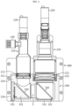
- FIG. 4 is a schematic cross-sectional view of the battery inspection device in FIG. 2 .
- the battery inspection device may include an upper inspection unit 100, a lower inspection unit 200, and a light-path guide unit 300.
- the upper inspection unit 100 and the lower inspection unit 200 may be configured to photograph different portions of one inspection object.
- the upper inspection unit 100 may be configured to photograph the upper area of the battery 20, which is the inspection object, and performing inspection for defects
- the lower inspection unit 200 may be configured to photograph the lower area inside the battery 20, which is the inspection object, and performing inspection for defects.
- the upper inspection unit 100 may include a first lens module 110 to condense first light incident from the inspection object, and a first camera 120 that is detachably coupled to the first lens module 110.
- the first lens module 110 may include a substantially cylindrical barrel and at least one lens 111 inside the barrel.
- the first camera 120 is a means for obtaining and storing images of the inspection object.
- the first camera 120 obtains and stores images of the upper weld area of the battery.
- the first camera 120 may be, for example, a CCD (Charge-Coupled Device) camera that uses a CCD as an image sensor to convert images into electrical signals and store digital data thereof in a storage medium such as flash memory.
- CCD Charge-Coupled Device
- the lower inspection unit 200 may include a second lens module 210 to condense second light incident from the inspection object, and a second camera 220 that is detachably coupled to the second lens module 210.
- the second lens module 210 may include a substantially cylindrical barrel and at least one lens 211 inside the barrel.
- the lens constituting the second lens module 210 may be a telecentric lens.
- the telecentric lens indicates a lens designed to bring parallel light, regardless of the parallel distance. Since this telecentric lens receives only the light parallel to the optical axis, there is no perspective error, so it is possible to more accurately inspect the weld thickness or the like, even it is the weld area in the lower area inside the battery.
- the second camera 220 is a means for obtaining and storing images of the inspection object and may be, for example, a CCD camera. However, the second camera 220 obtains and stores images of portions of the inspection object, which are different from those of the first camera 120. For example, in this embodiment, the first camera 120 obtains and stores an image of the upper area of the battery, and the second camera 220 obtains and stores an image of the lower area inside the battery.
- the light-path guide unit 300 may be configured to split the incident light incident from the inspection object into first light and second light, guide the first light to the first lens module 110, and guide the second light to the second lens module 210.
- the light-path guide unit 300 may include a beam splitter 320 and a reflective mirror 330.
- the beam splitter 320 indicates an optical device that splits a light beam into two or more beams.
- the beam splitter 320 may be configured to split incident light incident from the inspection object into first light and second light. That is, the first light is reflection light of the incident light, which is reflected from the beam splitter 320, and the second light is transmission light of the incident light, which passes through the beam splitter 320.
- the beam splitter 320 may be configured to reflect approximately 50% of the incident light and transmit approximately 50% of the incident light.
- the beam splitter 320 may be disposed vertically above the inspection object, and the second lens module 210 may be disposed vertically above the beam splitter 320.
- the second light may be incident directly on the second lens module 210.
- the first light is reflected from the beam splitter 320 and heads in the horizontal direction (the -Y-axis direction), the light path must be changed toward the first lens module 110.
- the reflective mirror 330 is a means for changing the light path of the first light, and may be disposed vertically below the first lens module 110 in order to guide the first light reflected from the beam splitter 320 to the first lens module 110.
- the light incident from the inspection object may be guided to the first lens module 110 and the second lens module 210 that are spaced apart from each other in the horizontal direction.
- the focus distance (or working distance) of the first lens module 110 is configured to be different from the focus distance of the second lens module 210, it is possible to simultaneously inspect different areas of one inspection object using the first lens module 110 and the second lens module 210.
- the light-path guide unit 300 may be integrally coupled to the first lens module 110 and the second lens module 210.
- the light-path guide unit 300 may include a barrel 310, a first lens connection hole 311, a second lens connection hole 312, and a light entrance 313.
- the barrel 310 may have a passage through which the first light and the second light pass and may be configured substantially in a box shape.
- the first lens connection hole 311 and the second lens connection hole 312 may be provided on the top of the barrel 310, respectively, as shown in FIG. 3 .
- the lower end of the first lens module 110 may be inserted and fixed into the first lens connection hole 311, and the lower end of the second lens module 210 may be inserted and fixed into the second lens connection hole 312.
- the lower lens of the first lens module 110 may face the inside of the barrel 310 through the first lens connection hole 311, and the lower lens of the second lens module 210 may face the inside of the barrel 310 through the second lens connection hole 312.
- the beam splitter 320 and the reflective mirror 330 are disposed inside the passage S of the barrel 310.
- the beam splitter 320 may be disposed vertically below the second lens connection hole 312, as shown in FIG. 4 .
- the light entrance 313 may be located vertically below the beam splitter 320.
- the beam splitter 320 may be configured in the form of a plate and assembled inside the passage of the barrel 310 such that the plate surface thereof forms an angle of about 45 degrees with the horizontal plane in a clockwise direction.
- Light incident through the light entrance 313 may be reflected and transmitted by the beam splitter 320. That is, in the case of the plate-shaped beam splitter 320 shown in FIG. 4 , some of the light vertically entering the barrel 310 through the light entrance 313 may be reflected by the plate-shaped beam splitter 320 such that the light path thereof turns 90 degrees to the left along the horizontal direction, and the remaining light may pass through the plate-shaped beam splitter 320 and proceed straight toward the second lens connection hole 312.
- the beam splitter 320 may be configured as a cube type.
- the reflective mirror 330 may be spaced apart from the beam splitter 320 in the horizontal direction and disposed vertically below the first lens connection hole 311. In addition, the reflective mirror 330 may be assembled inside the passage of the barrel 310 so as to form an angle of about 45 degrees with the horizontal plane in the clockwise direction.
- This reflective mirror 330 changes the travel direction of the first light, which is reflected from the beam splitter 320 and travels horizontally, to the vertical direction. Accordingly, the first light may be reflected from the reflective mirror 330 while changing its travel direction toward the first lens connection hole 311 and incident on the first lens module 110.
- the beam splitter 320 and the reflective mirror 330 may be provided to be inserted into and separated from the barrel 310.
- the light-path guide unit 300 may include a mirror support 331 that supports and holds the reflective mirror 330, and a splitter support 321 that supports and holds the beam splitter 320, and may be configured to have a slot through which the mirror support 331 and the splitter support 321 are able to be inserted into the barrel 310, respectively, from the outside.
- the barrel 310 may include a first insertion slot 315 into which the mirror support 331 is inserted on the left side.
- the mirror support 331 may be configured to be inserted into the barrel 310 from the outside through the first insertion slot 315. After the mirror support 331 is inserted into the barrel 310, the entrance of the first insertion slot 315 may be covered with a first slot cover plate 316, as shown in FIG. 6 .
- the barrel 310 may include a second insertion slot (not shown), into which the splitter support 321 is inserted, on the right front side.
- the second insertion slot may be formed from the front to the back of the barrel 310 (in the ⁇ X-axis directions).
- the splitter support 321 may be configured to be inserted into the barrel 310 from the outside through the second insertion slot. After the splitter support 321 is inserted into the barrel 310, the entrance of the second insertion slot may be covered with a second slot cover plate 314, as shown in FIG. 7 .
- the beam splitter 320 and the reflective mirror 330 may be easily disposed in or separated from the barrel 310. In addition, it may be easy to replace the reflective mirrors 330 or beam splitters 320 with different tilt angle, reflectance, and transmittance characteristics as needed.
- the battery inspection device may further include lighting equipment to obtain a bright image from the inspection object.
- the upper inspection unit 100 may include a first lighting equipment 130, and the first lighting equipment 130 and the first lens module 110 may be configured to be assembled with each other.
- the first lens module 110 may be configured to include a lighting detachable portion 113, to which the first lighting equipment 130 may be mounted, on one side of barrel, so that the first lighting equipment 130 may be coupled thereto.
- the first lighting equipment 130 may be coaxial projection lighting equipment.
- the lower inspection unit 200 may include a second lighting equipment 230, and the second lighting equipment 230 and the second lens module 210 may be configured to be assembled with each other.
- the second lens module 210 may be configured to include a lighting connection hole, to which the second lighting equipment 230 may be mounted, on one side of the barrel, so that the second lighting equipment 230 may be coupled thereto.
- the second lighting equipment 230 may be parallel-light lighting equipment.
- the lower inspection unit 200 may further include an aperture controller 240 capable of controlling the amount of light entering the second lens module 210 from the second lighting equipment 230.
- the aperture controller 240 may include an aperture unit 241, a motor bracket 242, a drive motor 243, and a timing belt 244.
- the aperture unit 241 may be mounted to the lighting connection hole (not shown) provided in the second lens module 210 for connection of the second lighting equipment 230, and may be configured such that a cogwheel 241a provided on the outer surface rotates clockwise or counterclockwise to gradually increase or reduce the diameter thereof, thereby adjusting the amount of light entering the lighting connection hole.
- the motor bracket 242 is fixed to the second lens module 210 and may be configured in a plate shape on which the drive motor 243 may be assembled.
- the drive motor 243 may include a main body fixed to the motor bracket 242 and a shaft 243a that rotates in the forward and reverse directions.
- the shaft 243a of the drive motor and the cogwheel 241a of the aperture unit may be connected by a timing belt 244.
- the lower inspection unit 200 may include the aperture controller 240 to automatically adjust the amount of light, and may control the number of rotations of the drive motor 243, thereby precisely adjusting the amount of light.
- the battery inspection device may further include a device bracket 400.
- the device bracket 400 may be coupled to the second lens module 210 and the light-path guide unit 300.
- This device bracket 400 although not shown, may be coupled to a transfer device (not shown) that is movable in 3-axis (X, Y, Z) directions. In this case, the battery inspection device may be moved up and down, left and right, and forward and backward relative to the inspection object.
- the cylindrical battery 20 which is the inspection object in this embodiment, is a tab-less cylindrical secondary battery, and has a central hole H at the center of the electrode assembly 23, as shown in FIG. 10 .
- the central hole H formed at the center of the electrode assembly 23 corresponds to the portion where a winding rod (not shown), which had been used to wind the electrode assembly therearound, was removed. Welding may be performed between the positive electrode terminal 25 and the positive electrode collector 27 provided in the lower area inside the cylindrical battery. In this case, a welding rod may be inserted into the central hole H of the electrode assembly 23 or a laser beam may be radiated through the central hole H of the electrode assembly 23, thereby performing welding.
- the cylindrical battery 20 has a negative electrode collector 26 in the upper area. The edge of the negative electrode collector 26 may be welded to the inner surface of the battery can, and its lower surface may be welded to a negative electrode uncoated portion.
- the lower inspection unit 200 of the battery inspection device may inspect the lower area 22 inside the battery where the positive electrode terminal 25 and the positive electrode collector 27 are welded to each other.
- the upper inspection unit 100 of the battery inspection device may inspect the upper area 21 of the battery where the negative electrode collector 26 is assembled.
- the cylindrical battery 20 may be transported, for example, by a transport device such as a conveyor.
- the battery inspection device of the present disclosure may photograph, at high speed, the cylindrical battery 20 being transported during the battery production process, thereby obtaining an image of the inspection target area.
- the upper inspection unit 100 of the battery inspection device photographs the upper area 21 of the cylindrical battery
- the lower inspection unit 200 photographs the lower area 22 inside the cylindrical battery.
- the first lens module 110 and the second lens module 210 may have different focus distances (working distances).
- the first lens module 110 may be configured with a focus distance from its lower lens to the surface of the upper area 21 of the cylindrical battery to be viewed. In this case, a clear image of the upper area 21 of the cylindrical battery may be obtained using the first lens module 110.
- the second lens module 210 may be configured with a focus distance from its lower lens to the surface of the lower area 22 inside the cylindrical battery to be viewed. In this case, a clear image of the lower area 22 inside the cylindrical battery may be obtained using the second lens module 210.
- the battery inspection device is located to be spaced upward from the cylindrical battery 20 and photographs each cylindrical battery being transported, thereby performing inspection for defects. Specifically, when the cylindrical battery 20 being transported is located below the light entrance 313 of the light-path guide unit 300, the first lighting equipment 130 is turned on and the first camera 120 obtains an image of the upper area 21 of the cylindrical battery. At this time, as shown in FIG. 11 , incident light L incident on the light entrance 313 from the upper area 21 of the cylindrical battery may be split into first light L1 and second light L2 by the beam splitter 320, so that the first light L1 may reach the image sensor of the first camera 120 through the reflective mirror 330 and the first lens module 110, thereby obtaining an image of the upper area 21 of the cylindrical battery.
- the second lighting equipment 230 of the lower inspection unit 200 may be turned on with a very short time difference from the first lighting equipment 130.
- the first lighting equipment 130 may be turned off.
- the second lighting equipment 230 is turned on, the second camera 220 obtains an image of the lower area 22 inside the cylindrical battery.
- incident light L incident from the lower area 22 inside the cylindrical battery to the light entrance 313 may be split into first light L1 and second light L2 by the beam splitter 320, so that the second light L2 may reach the image sensor of the second camera 220 through the second lens module 210, thereby obtaining an image of the lower area 22 inside the cylindrical battery.
Landscapes
- Physics & Mathematics (AREA)
- Chemical & Material Sciences (AREA)
- General Physics & Mathematics (AREA)
- Analytical Chemistry (AREA)
- General Health & Medical Sciences (AREA)
- Pathology (AREA)
- Immunology (AREA)
- Health & Medical Sciences (AREA)
- Life Sciences & Earth Sciences (AREA)
- Biochemistry (AREA)
- Engineering & Computer Science (AREA)
- Optics & Photonics (AREA)
- General Chemical & Material Sciences (AREA)
- Electrochemistry (AREA)
- Chemical Kinetics & Catalysis (AREA)
- Manufacturing & Machinery (AREA)
- Quality & Reliability (AREA)
- Computer Vision & Pattern Recognition (AREA)
- Theoretical Computer Science (AREA)
- Investigating Materials By The Use Of Optical Means Adapted For Particular Applications (AREA)
Abstract
Description
- The present disclosure relates to a device for inspecting battery quality in the battery production process, and more specifically, it relates to an inspection device for inspecting the quality of welded or assembled areas.
- The present application claims priority to
Korean Patent Application No. 10-2022-0173077 filed on December 12, 2022 Korean Patent Application No. 10-2023-0174956 filed on December 05, 2023 - An existing inspection device for weld areas of a cylindrical battery, as shown in
FIG. 1 , inspects the lower weld area by inserting an endoscope lens 1 into thebattery 20. - The inspection using the above method makes it difficult to respond to fast production line speeds due to limited ascending and descending speeds of the endoscope lens 1. In addition, insertion of the endoscope lens 1 into the
battery 20 requires the product to stop at the inspection section in the battery production process. - There is also a problem with batteries and inspection devices being damaged when inserting the endoscope lens.
- Accordingly, a new type of cylindrical-battery weld inspection device capable of inspecting defects occurring in the welding process with improved image quality is required to replace the endoscopic lens insertion-type inspection device that disrupts tact time and causes damage to the battery and inspection device.
- The present disclosure has been designed to solve the problems of the related art, and therefore the present disclosure is directed to providing an inspection device capable of inspecting the battery quality without stopping the production line in the battery production process, eliminating the risk of damage to the product or inspection device during the battery inspection process, and more accurate inspection.
- The present disclosure is also to provide an inspection device capable of simultaneously inspecting the upper weld area and appearance of the battery, as well as the lower weld area thereof.
- However, the technical problems that the present disclosure seeks to solve are not limited to the above-mentioned problems, and other problems not mentioned above will be clearly understood by those skilled in the art from the description of the invention described below.
- According to one aspect of the present disclosure, there is provided a battery inspection device according to an aspect of the present disclosure may include: an upper inspection unit including a first lens module configured to condense first light and a first camera mounted on the top of the first lens module; a lower inspection unit disposed horizontally to be spaced apart from the first lens module and comprising a second lens module configured to condense second light and a second camera mounted on the top of the second lens module; and a light-path guide unit integrally coupled to the first lens module and the second lens module and configured to split incident light incident from an inspection object into the first light and the second light, guide the first light to the first lens module, and guide the second light to the first lens module.
- The light-path guide unit may include: a beam splitter configured to split the incident light into the first light and the second light; and a reflective mirror configured to refract the first light toward the first lens module.
- The light-path guide unit may include: a barrel configured in the shape of a box and having a passage through which the first light and the second light pass; a first lens connection hole provided on the top of the barrel and to which the first lens module is connected; a second lens connection hole provided on the top of the barrel and to which the second lens module is connected; and a light entrance provided on the bottom of the barrel and through which light enters and exits the barrel.
- Inside the passage, the reflective mirror may be disposed vertically below the first lens connection hole and the beam splitter may be disposed vertically below the second lens connection hole, and the light entrance may be provided vertically below the beam splitter.
- The light-path guide unit may include: a mirror support configured to support and hold the reflective mirror; a splitter support configured to support and hold the beam splitter; and slots through which the mirror support and the splitter support are inserted into the barrel from the outside.
- The second lens module may include a telecentric lens.
- The upper inspection unit may include a first lighting equipment coupled to the first lens module.
- The first lighting equipment may be coaxial projection lighting equipment.
- The lower inspection unit may include a second lighting equipment coupled to the second lens module.
- The second lighting equipment may be parallel-light lighting equipment.
- The lower inspection unit may include an aperture controller capable of controlling the amount of light entering the second lens module from the second lighting equipment.
- The aperture controller may include: an aperture unit mounted to a lighting connection hole provided in the second lens module for connection of the second lighting equipment, and configured such that a cogwheel provided on the outer surface rotates clockwise or counterclockwise to gradually increase or reduce the diameter thereof, thereby adjusting the amount of light entering the lighting connection hole; a motor bracket coupled to the outer side of the second lens module; a drive motor fixed to the bracket; and a timing belt connected to the drive motor and the cogwheel.
- According to one aspect of the present disclosure, it is possible to provide an inspection device capable of inspecting the battery quality without stopping the production line in the battery production process, eliminating the risk of damage to the product or inspection device during the battery inspection process, and more accurate inspection.
- The present disclosure is able to simultaneously inspect the upper weld area of the battery, as well as the lower weld area thereof, thereby significantly reducing the tact time of the battery inspection process.
- The effects obtainable from the present disclosure are not limited to the above-mentioned effects, and other effects not mentioned above will be clearly understood by those skilled in the art to which the present disclosure pertains from the description of the invention described below.
-
-
FIG. 1 is a diagram schematically illustrating a battery inspection device according to the prior art. -
FIG. 2 is a perspective view of a battery inspection device according to an embodiment of the present disclosure. -
FIG. 3 is an exploded perspective view of the battery inspection device inFIG. 2 . -
FIG. 4 is a schematic cross-sectional view of the battery inspection device inFIG. 2 . -
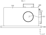
FIG. 5 is a bottom view of the battery inspection device inFIG. 2 . -
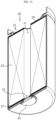
FIG. 6 is a left side view of the battery inspection device inFIG. 2 . -
FIG. 7 is a front view of the battery inspection device inFIG. 2 . -
FIG. 8 is a right side view of the battery inspection device inFIG. 2 . -
FIG. 9 is a diagram illustrating an aperture controller of the battery inspection device inFIG. 2 . -
FIG. 10 is a cutaway view schematically illustrating a battery for inspection using a battery inspection device according to an embodiment of the present disclosure. -
FIG. 11 is a diagram illustrating the light path for inspection of an upper area in the battery when photographing the upper area of the battery using an upper inspection unit according to an embodiment of the present disclosure. -
FIG. 12 is a diagram illustrating the light path for inspection of a lower area in battery when photographing the lower area of the battery using a lower inspection unit according to an embodiment of the present disclosure. - Hereinafter, preferred embodiments of the present disclosure will be described in detail with reference to the accompanying drawings. Prior to the description, it should be understood that the terms used in the specification and the appended claims should not be construed as limited to general and dictionary meanings, but interpreted based on the meanings and concepts corresponding to technical aspects of the present disclosure on the basis of the principle that the inventor is allowed to define terms appropriately for the best explanation. Therefore, the configurations proposed in the embodiments and drawings of this specification indicate only the most preferable embodiment of the present disclosure and do not represent all technical ideas of the present disclosure, so it should be understood that various equivalents and modifications could be made thereto at the time of filing the application.
- A battery inspection device according to the present disclosure may inspect the upper and lower areas of a battery during the battery production process to check for defects.
- As will be described in detail later, the battery inspection device according to the present disclosure is configured to simultaneously obtain images of the upper and lower areas of a
battery 20 while thebattery 20 is moving in the battery production line and inspect the states of the upper and lower areas of the battery. Therefore, it is possible to inspect the battery quality without stopping the production line in the battery production process, thereby reducing the tact time of the battery production process according thereto. In addition, compared to the endoscopic inspection method described in the background above, the battery inspection device according to the present disclosure is configured to obtain an image of the lower area inside the battery from the outside of the battery, avoiding interference or collision between the battery inspection device and the battery. - Hereinafter, primary elements of the battery inspection device according to the present disclosure will be described in detail.
-
FIG. 2 is a perspective view of a battery inspection device according to an embodiment of the present disclosure,FIG. 3 is an exploded perspective view of the battery inspection device inFIG. 2 , andFIG. 4 is a schematic cross-sectional view of the battery inspection device inFIG. 2 . - As shown in
FIGS. 2 to 4 , the battery inspection device according to an embodiment of the present disclosure may include anupper inspection unit 100, alower inspection unit 200, and a light-path guide unit 300. - The
upper inspection unit 100 and thelower inspection unit 200 may be configured to photograph different portions of one inspection object. For example, theupper inspection unit 100 may be configured to photograph the upper area of thebattery 20, which is the inspection object, and performing inspection for defects, and thelower inspection unit 200 may be configured to photograph the lower area inside thebattery 20, which is the inspection object, and performing inspection for defects. - The
upper inspection unit 100 may include afirst lens module 110 to condense first light incident from the inspection object, and afirst camera 120 that is detachably coupled to thefirst lens module 110. Thefirst lens module 110 may include a substantially cylindrical barrel and at least onelens 111 inside the barrel. - The
first camera 120 is a means for obtaining and storing images of the inspection object. In the present embodiment, thefirst camera 120 obtains and stores images of the upper weld area of the battery. Thefirst camera 120 may be, for example, a CCD (Charge-Coupled Device) camera that uses a CCD as an image sensor to convert images into electrical signals and store digital data thereof in a storage medium such as flash memory. - The
lower inspection unit 200 may include asecond lens module 210 to condense second light incident from the inspection object, and asecond camera 220 that is detachably coupled to thesecond lens module 210. Thesecond lens module 210 may include a substantially cylindrical barrel and at least onelens 211 inside the barrel. In particular, in this embodiment, the lens constituting thesecond lens module 210 may be a telecentric lens. Here, the telecentric lens indicates a lens designed to bring parallel light, regardless of the parallel distance. Since this telecentric lens receives only the light parallel to the optical axis, there is no perspective error, so it is possible to more accurately inspect the weld thickness or the like, even it is the weld area in the lower area inside the battery. - Like the
first camera 120, thesecond camera 220 is a means for obtaining and storing images of the inspection object and may be, for example, a CCD camera. However, thesecond camera 220 obtains and stores images of portions of the inspection object, which are different from those of thefirst camera 120. For example, in this embodiment, thefirst camera 120 obtains and stores an image of the upper area of the battery, and thesecond camera 220 obtains and stores an image of the lower area inside the battery. - The light-
path guide unit 300 may be configured to split the incident light incident from the inspection object into first light and second light, guide the first light to thefirst lens module 110, and guide the second light to thesecond lens module 210. - To this end, the light-
path guide unit 300 according to the present embodiment may include abeam splitter 320 and areflective mirror 330. Here, thebeam splitter 320 indicates an optical device that splits a light beam into two or more beams. In this embodiment, thebeam splitter 320 may be configured to split incident light incident from the inspection object into first light and second light. That is, the first light is reflection light of the incident light, which is reflected from thebeam splitter 320, and the second light is transmission light of the incident light, which passes through thebeam splitter 320. For example, thebeam splitter 320 may be configured to reflect approximately 50% of the incident light and transmit approximately 50% of the incident light. - The
beam splitter 320 may be disposed vertically above the inspection object, and thesecond lens module 210 may be disposed vertically above thebeam splitter 320. In this case, the second light may be incident directly on thesecond lens module 210. However, since the first light is reflected from thebeam splitter 320 and heads in the horizontal direction (the -Y-axis direction), the light path must be changed toward thefirst lens module 110. - The
reflective mirror 330 is a means for changing the light path of the first light, and may be disposed vertically below thefirst lens module 110 in order to guide the first light reflected from thebeam splitter 320 to thefirst lens module 110. - According to this configuration, the light incident from the inspection object may be guided to the
first lens module 110 and thesecond lens module 210 that are spaced apart from each other in the horizontal direction. In addition, for example, if the focus distance (or working distance) of thefirst lens module 110 is configured to be different from the focus distance of thesecond lens module 210, it is possible to simultaneously inspect different areas of one inspection object using thefirst lens module 110 and thesecond lens module 210. - The light-
path guide unit 300 may be integrally coupled to thefirst lens module 110 and thesecond lens module 210. - Specifically, referring to
FIGS. 3 to 5 , the light-path guide unit 300 may include abarrel 310, a firstlens connection hole 311, a secondlens connection hole 312, and alight entrance 313. - The
barrel 310 may have a passage through which the first light and the second light pass and may be configured substantially in a box shape. - The first
lens connection hole 311 and the secondlens connection hole 312 may be provided on the top of thebarrel 310, respectively, as shown inFIG. 3 . The lower end of thefirst lens module 110 may be inserted and fixed into the firstlens connection hole 311, and the lower end of thesecond lens module 210 may be inserted and fixed into the secondlens connection hole 312. - In this case, as shown in
FIG. 4 , the lower lens of thefirst lens module 110 may face the inside of thebarrel 310 through the firstlens connection hole 311, and the lower lens of thesecond lens module 210 may face the inside of thebarrel 310 through the secondlens connection hole 312. - The
light entrance 313 may be provided on the bottom of thebarrel 310. Light incident from the inspection object may enter thebarrel 310 through thelight entrance 313. In addition, as will be described later, illumination light for illuminating the inspection object may pass from the inside of thebarrel 310 to the outside through thelight entrance 313. - In this embodiment, the
beam splitter 320 and thereflective mirror 330 are disposed inside the passage S of thebarrel 310. Specifically, thebeam splitter 320 may be disposed vertically below the secondlens connection hole 312, as shown inFIG. 4 . In addition, thelight entrance 313 may be located vertically below thebeam splitter 320. - The
beam splitter 320 may be configured in the form of a plate and assembled inside the passage of thebarrel 310 such that the plate surface thereof forms an angle of about 45 degrees with the horizontal plane in a clockwise direction. Light incident through thelight entrance 313 may be reflected and transmitted by thebeam splitter 320. That is, in the case of the plate-shapedbeam splitter 320 shown inFIG. 4 , some of the light vertically entering thebarrel 310 through thelight entrance 313 may be reflected by the plate-shapedbeam splitter 320 such that the light path thereof turns 90 degrees to the left along the horizontal direction, and the remaining light may pass through the plate-shapedbeam splitter 320 and proceed straight toward the secondlens connection hole 312. Here, among the two light beams split by thebeam splitter 320, the light beam whose light path is changed by being reflected from thebeam splitter 320 corresponds to the first light, and the light beam passing through thebeam splitter 320 corresponds to the second light. Meanwhile, although thebeam splitter 320 of this embodiment is of a plate type, thebeam splitter 320 may be configured as a cube type. - The
reflective mirror 330 may be spaced apart from thebeam splitter 320 in the horizontal direction and disposed vertically below the firstlens connection hole 311. In addition, thereflective mirror 330 may be assembled inside the passage of thebarrel 310 so as to form an angle of about 45 degrees with the horizontal plane in the clockwise direction. - This
reflective mirror 330 changes the travel direction of the first light, which is reflected from thebeam splitter 320 and travels horizontally, to the vertical direction. Accordingly, the first light may be reflected from thereflective mirror 330 while changing its travel direction toward the firstlens connection hole 311 and incident on thefirst lens module 110. - Meanwhile, the
beam splitter 320 and thereflective mirror 330 may be provided to be inserted into and separated from thebarrel 310. - For example, the light-
path guide unit 300 according to this embodiment may include amirror support 331 that supports and holds thereflective mirror 330, and asplitter support 321 that supports and holds thebeam splitter 320, and may be configured to have a slot through which themirror support 331 and thesplitter support 321 are able to be inserted into thebarrel 310, respectively, from the outside. - For example, as shown in
FIG. 4 , thebarrel 310 may include afirst insertion slot 315 into which themirror support 331 is inserted on the left side. Themirror support 331 may be configured to be inserted into thebarrel 310 from the outside through thefirst insertion slot 315. After themirror support 331 is inserted into thebarrel 310, the entrance of thefirst insertion slot 315 may be covered with a firstslot cover plate 316, as shown inFIG. 6 . - In addition, the
barrel 310 may include a second insertion slot (not shown), into which thesplitter support 321 is inserted, on the right front side. The second insertion slot may be formed from the front to the back of the barrel 310 (in the ±X-axis directions). Thesplitter support 321 may be configured to be inserted into thebarrel 310 from the outside through the second insertion slot. After thesplitter support 321 is inserted into thebarrel 310, the entrance of the second insertion slot may be covered with a secondslot cover plate 314, as shown inFIG. 7 . - According to this configuration, the
beam splitter 320 and thereflective mirror 330 may be easily disposed in or separated from thebarrel 310. In addition, it may be easy to replace thereflective mirrors 330 orbeam splitters 320 with different tilt angle, reflectance, and transmittance characteristics as needed. - Referring back to
FIGS. 2 and3 , the battery inspection device according to an embodiment of the present disclosure may further include lighting equipment to obtain a bright image from the inspection object. - The
upper inspection unit 100 may include afirst lighting equipment 130, and thefirst lighting equipment 130 and thefirst lens module 110 may be configured to be assembled with each other. Thefirst lens module 110 may be configured to include a lightingdetachable portion 113, to which thefirst lighting equipment 130 may be mounted, on one side of barrel, so that thefirst lighting equipment 130 may be coupled thereto. In this embodiment, thefirst lighting equipment 130 may be coaxial projection lighting equipment. - The
lower inspection unit 200 may include asecond lighting equipment 230, and thesecond lighting equipment 230 and thesecond lens module 210 may be configured to be assembled with each other. Thesecond lens module 210 may be configured to include a lighting connection hole, to which thesecond lighting equipment 230 may be mounted, on one side of the barrel, so that thesecond lighting equipment 230 may be coupled thereto. In this embodiment, thesecond lighting equipment 230 may be parallel-light lighting equipment. - In particular, the
lower inspection unit 200 may further include anaperture controller 240 capable of controlling the amount of light entering thesecond lens module 210 from thesecond lighting equipment 230. - As shown in
FIG. 9 , theaperture controller 240 may include anaperture unit 241, amotor bracket 242, adrive motor 243, and atiming belt 244. - The
aperture unit 241 may be mounted to the lighting connection hole (not shown) provided in thesecond lens module 210 for connection of thesecond lighting equipment 230, and may be configured such that acogwheel 241a provided on the outer surface rotates clockwise or counterclockwise to gradually increase or reduce the diameter thereof, thereby adjusting the amount of light entering the lighting connection hole. - The
motor bracket 242 is fixed to thesecond lens module 210 and may be configured in a plate shape on which thedrive motor 243 may be assembled. - The
drive motor 243 may include a main body fixed to themotor bracket 242 and ashaft 243a that rotates in the forward and reverse directions. Theshaft 243a of the drive motor and thecogwheel 241a of the aperture unit may be connected by atiming belt 244. - As described above, the
lower inspection unit 200 may include theaperture controller 240 to automatically adjust the amount of light, and may control the number of rotations of thedrive motor 243, thereby precisely adjusting the amount of light. - Meanwhile, the battery inspection device according to an embodiment of the present disclosure may further include a
device bracket 400. Referring toFIGS. 2 to 3 and8 , thedevice bracket 400 may be coupled to thesecond lens module 210 and the light-path guide unit 300. Thisdevice bracket 400, although not shown, may be coupled to a transfer device (not shown) that is movable in 3-axis (X, Y, Z) directions. In this case, the battery inspection device may be moved up and down, left and right, and forward and backward relative to the inspection object. - Next, an inspection process for the
upper area 21 andlower area 22 of the cylindrical battery, which may be performed by the battery inspection device according to the present disclosure, will be briefly described with reference toFIGS. 10 to 12 . - The
cylindrical battery 20, which is the inspection object in this embodiment, is a tab-less cylindrical secondary battery, and has a central hole H at the center of theelectrode assembly 23, as shown inFIG. 10 . The central hole H formed at the center of theelectrode assembly 23 corresponds to the portion where a winding rod (not shown), which had been used to wind the electrode assembly therearound, was removed. Welding may be performed between thepositive electrode terminal 25 and thepositive electrode collector 27 provided in the lower area inside the cylindrical battery. In this case, a welding rod may be inserted into the central hole H of theelectrode assembly 23 or a laser beam may be radiated through the central hole H of theelectrode assembly 23, thereby performing welding. In addition, thecylindrical battery 20 has anegative electrode collector 26 in the upper area. The edge of thenegative electrode collector 26 may be welded to the inner surface of the battery can, and its lower surface may be welded to a negative electrode uncoated portion. - In this embodiment, the
lower inspection unit 200 of the battery inspection device may inspect thelower area 22 inside the battery where thepositive electrode terminal 25 and thepositive electrode collector 27 are welded to each other. In addition, theupper inspection unit 100 of the battery inspection device may inspect theupper area 21 of the battery where thenegative electrode collector 26 is assembled. - During the battery production process, the
cylindrical battery 20 may be transported, for example, by a transport device such as a conveyor. The battery inspection device of the present disclosure may photograph, at high speed, thecylindrical battery 20 being transported during the battery production process, thereby obtaining an image of the inspection target area. - The
upper inspection unit 100 of the battery inspection device photographs theupper area 21 of the cylindrical battery, and thelower inspection unit 200 photographs thelower area 22 inside the cylindrical battery. To this end, thefirst lens module 110 and thesecond lens module 210 may have different focus distances (working distances). - For example, in this embodiment, the
first lens module 110 may be configured with a focus distance from its lower lens to the surface of theupper area 21 of the cylindrical battery to be viewed. In this case, a clear image of theupper area 21 of the cylindrical battery may be obtained using thefirst lens module 110. In addition, in this embodiment, thesecond lens module 210 may be configured with a focus distance from its lower lens to the surface of thelower area 22 inside the cylindrical battery to be viewed. In this case, a clear image of thelower area 22 inside the cylindrical battery may be obtained using thesecond lens module 210. - The battery inspection device is located to be spaced upward from the
cylindrical battery 20 and photographs each cylindrical battery being transported, thereby performing inspection for defects. Specifically, when thecylindrical battery 20 being transported is located below thelight entrance 313 of the light-path guide unit 300, thefirst lighting equipment 130 is turned on and thefirst camera 120 obtains an image of theupper area 21 of the cylindrical battery. At this time, as shown inFIG. 11 , incident light L incident on thelight entrance 313 from theupper area 21 of the cylindrical battery may be split into first light L1 and second light L2 by thebeam splitter 320, so that the first light L1 may reach the image sensor of thefirst camera 120 through thereflective mirror 330 and thefirst lens module 110, thereby obtaining an image of theupper area 21 of the cylindrical battery. - The
second lighting equipment 230 of thelower inspection unit 200 may be turned on with a very short time difference from thefirst lighting equipment 130. When thesecond lighting equipment 230 is turned on, thefirst lighting equipment 130 may be turned off. When thesecond lighting equipment 230 is turned on, thesecond camera 220 obtains an image of thelower area 22 inside the cylindrical battery. At this time, as shown inFIG. 12 , incident light L incident from thelower area 22 inside the cylindrical battery to thelight entrance 313 may be split into first light L1 and second light L2 by thebeam splitter 320, so that the second light L2 may reach the image sensor of thesecond camera 220 through thesecond lens module 210, thereby obtaining an image of thelower area 22 inside the cylindrical battery. - Since the photographing of the
upper area 21 of the cylindrical battery by theupper inspection unit 100 and the photographing of thelower area 22 inside the cylindrical battery by thelower inspection unit 200 are performed very quickly, they actually take place almost simultaneously. Therefore, it is possible to obtain images of theupper area 21 and thelower area 22 of the cylindrical battery without stopping the production line in the battery production process and inspect the welding quality of corresponding areas or the like. - As described above, although the present disclosure has been described with reference to limited embodiments and drawings, the present disclosure is not limited thereto, and various modifications and variations are possible within the technical idea of the present disclosure and the scope of equivalence of the claims to be described below by those skilled in the art to which the present disclosure pertains.
- Meanwhile, although terms indicating directions such as upward, downward, left, right, forward, and backward directions are used in this specification, it is obvious to those skilled in the art that these terms are only for convenience of explanation and may vary depending on the location of the target object or the location of the observer.
Claims (12)
- A battery inspection device comprising:an upper inspection unit comprising a first lens module configured to condense first light and a first camera mounted on the top of the first lens module;a lower inspection unit disposed horizontally to be spaced apart from the first lens module and comprising a second lens module configured to condense second light and a second camera mounted on the top of the second lens module; anda light-path guide unit integrally coupled to the first lens module and the second lens module and configured to split incident light incident from an inspection object into the first light and the second light, guide the first light to the first lens module, and guide the second light to the first lens module.
- The battery inspection device according to claim 1,
wherein the light-path guide unit comprises:a beam splitter configured to split the incident light into the first light and the second light; anda reflective mirror configured to refract the first light toward the first lens module. - The battery inspection device according to claim 2,
wherein the light-path guide unit comprises:a barrel configured in the shape of a box and having a passage through which the first light and the second light pass;a first lens connection hole provided on the top of the barrel and to which the first lens module is connected;a second lens connection hole provided on the top of the barrel and to which the second lens module is connected; anda light entrance provided on the bottom of the barrel and through which light enters and exits the barrel. - The battery inspection device according to claim 3,wherein, inside the passage, the reflective mirror is disposed vertically below the first lens connection hole and the beam splitter is disposed vertically below the second lens connection hole, andwherein the light entrance is provided vertically below the beam splitter.
- The battery inspection device according to claim 3,
wherein the light-path guide unit comprises:a mirror support configured to support and hold the reflective mirror;a splitter support configured to support and hold the beam splitter; andslots through which the mirror support and the splitter support are inserted into the barrel from the outside. - The battery inspection device according to claim 1,
wherein the second lens module comprises a telecentric lens. - The battery inspection device according to claim 1,wherein the upper inspection unit comprisesa first lighting equipment coupled to the first lens module.
- The battery inspection device according to claim 7,
wherein the first lighting equipment is coaxial projection lighting equipment. - The battery inspection device according to claim 1,wherein the lower inspection unit comprisesa second lighting equipment coupled to the second lens module.
- The battery inspection device according to claim 9,
wherein the second lighting equipment is parallel-light lighting equipment. - The battery inspection device according to claim 9,wherein the lower inspection unit comprisesan aperture controller capable of controlling the amount of light entering the second lens module from the second lighting equipment.
- The battery inspection device according to claim 11,
wherein the aperture controller comprises:an aperture unit mounted to a lighting connection hole provided in the second lens module for connection of the second lighting equipment, and configured such that a cogwheel provided on the outer surface rotates clockwise or counterclockwise to gradually increase or reduce the diameter thereof, thereby adjusting the amount of light entering the lighting connection hole;a motor bracket coupled to the outer side of the second lens module;a drive motor fixed to the bracket; anda timing belt connected to the drive motor and the cogwheel.
Applications Claiming Priority (3)
| Application Number | Priority Date | Filing Date | Title |
|---|---|---|---|
| KR20220173077 | 2022-12-12 | ||
| KR1020230174956A KR20240087577A (en) | 2022-12-12 | 2023-12-05 | battery inspection equipment |
| PCT/KR2023/020453 WO2024128766A1 (en) | 2022-12-12 | 2023-12-12 | Battery inspection device |
Publications (2)
| Publication Number | Publication Date |
|---|---|
| EP4542205A1 true EP4542205A1 (en) | 2025-04-23 |
| EP4542205A4 EP4542205A4 (en) | 2025-11-26 |
Family
ID=91485377
Family Applications (1)
| Application Number | Title | Priority Date | Filing Date |
|---|---|---|---|
| EP23903968.8A Pending EP4542205A4 (en) | 2022-12-12 | 2023-12-12 | BATTERY INSPECTION DEVICE |
Country Status (5)
| Country | Link |
|---|---|
| US (1) | US20250369896A1 (en) |
| EP (1) | EP4542205A4 (en) |
| JP (1) | JP2025526048A (en) |
| CN (1) | CN119422052A (en) |
| WO (1) | WO2024128766A1 (en) |
Family Cites Families (20)
| Publication number | Priority date | Publication date | Assignee | Title |
|---|---|---|---|---|
| JP2946890B2 (en) * | 1991-12-02 | 1999-09-06 | 松下電器産業株式会社 | Substrate observation device |
| JP3353923B2 (en) * | 1992-11-18 | 2002-12-09 | オリンパス光学工業株式会社 | Aperture control device |
| JPH0963547A (en) * | 1995-08-16 | 1997-03-07 | Fuji Elelctrochem Co Ltd | Inspection method for can opening |
| US6175645B1 (en) * | 1998-01-22 | 2001-01-16 | Applied Materials, Inc. | Optical inspection method and apparatus |
| JP2001043834A (en) * | 1999-08-02 | 2001-02-16 | Toshiba Battery Co Ltd | Battery outer case inspection device |
| JP2004205218A (en) * | 2002-12-20 | 2004-07-22 | Nec Tohoku Ltd | Device and method of inspecting appearance of inside diameter part |
| JP4825172B2 (en) * | 2007-06-08 | 2011-11-30 | 株式会社新川 | Imaging apparatus for bonding apparatus and imaging method |
| JP5352111B2 (en) * | 2008-04-16 | 2013-11-27 | 株式会社日立ハイテクノロジーズ | Defect inspection method and defect inspection apparatus using the same |
| SG157977A1 (en) * | 2008-06-23 | 2010-01-29 | Semiconductor Tech & Instr Inc | System and method for inspection of semiconductor packages |
| SG164292A1 (en) * | 2009-01-13 | 2010-09-29 | Semiconductor Technologies & Instruments Pte | System and method for inspecting a wafer |
| DE102009044151B4 (en) * | 2009-05-19 | 2012-03-29 | Kla-Tencor Mie Gmbh | Device for optical wafer inspection |
| CN102095736B (en) * | 2010-10-29 | 2012-06-27 | 华南理工大学 | Dual-optical-magnification image acquisition device and image acquisition control and process system |
| KR101314539B1 (en) * | 2013-04-29 | 2013-10-04 | 주식회사 미르기술 | Vision inspection appartus using dual coaxial camera |
| KR101894961B1 (en) * | 2016-09-29 | 2018-09-05 | 주식회사 제이이노텍 | Apparatus for inspecting welding state of cylindrical battery |
| KR101755615B1 (en) * | 2016-11-14 | 2017-07-19 | 주식회사 인스풀 | Optical apparatus and optical inspecting apparatus having the same |
| CN106825958B (en) * | 2017-03-16 | 2018-09-28 | 深圳市光大激光科技股份有限公司 | Battery core automatic welding detection device and method |
| CN107084993A (en) * | 2017-06-21 | 2017-08-22 | 无锡九霄科技有限公司 | Double camera single-station positive and negative vision inspection apparatus |
| JP7396876B2 (en) * | 2019-11-27 | 2023-12-12 | ファナック株式会社 | Internal image inspection device and internal image inspection system |
| PL4431920T3 (en) * | 2021-11-08 | 2026-04-27 | Lg Energy Solution, Ltd. | Welding inspection device and welding inspection method |
| KR102846629B1 (en) | 2022-06-22 | 2025-08-14 | 주식회사 신흥이엔씨 | Water and wastewater treatment plant safety management system using beacon |
-
2023
- 2023-12-12 CN CN202380048852.5A patent/CN119422052A/en active Pending
- 2023-12-12 WO PCT/KR2023/020453 patent/WO2024128766A1/en not_active Ceased
- 2023-12-12 JP JP2025507403A patent/JP2025526048A/en active Pending
- 2023-12-12 US US18/873,817 patent/US20250369896A1/en active Pending
- 2023-12-12 EP EP23903968.8A patent/EP4542205A4/en active Pending
Also Published As
| Publication number | Publication date |
|---|---|
| WO2024128766A1 (en) | 2024-06-20 |
| JP2025526048A (en) | 2025-08-07 |
| US20250369896A1 (en) | 2025-12-04 |
| CN119422052A (en) | 2025-02-11 |
| EP4542205A4 (en) | 2025-11-26 |
Similar Documents
| Publication | Publication Date | Title |
|---|---|---|
| JP5895305B2 (en) | Inspection illumination device and inspection illumination method | |
| KR101105679B1 (en) | Vision inspection device | |
| CN107797270B (en) | Optical device, processing device, and article manufacturing method | |
| US10175041B2 (en) | Measuring head and eccentricity measuring device including the same | |
| KR102539716B1 (en) | Apparatus for secondary battery appearance inspection | |
| JP2018032005A (en) | Autofocus system, method and image inspection device | |
| CN117929271A (en) | Chip imaging detection device and method | |
| CN114813056B (en) | A device and method for detecting defects in curved screens | |
| US20250369896A1 (en) | Battery Inspection Device | |
| CN115712201A (en) | Passive coupling system and coupling method | |
| KR20240087577A (en) | battery inspection equipment | |
| JP4669350B2 (en) | Optical part and mold processing method | |
| TWI686660B (en) | Imaging apparatus | |
| JPH02278971A (en) | Steel camera | |
| KR20150077596A (en) | Substrate inspecting apparatus and inspecting method using the same | |
| KR20240152709A (en) | Apparatus for inspecting inside of Prismatic can for secondary battery | |
| JP4783335B2 (en) | Component recognition device, surface mounter | |
| CN100573297C (en) | Picture pick-up device and elevation mount | |
| CN106291854B (en) | A kind of motion platform and the device and method of optical path installation and adjustment | |
| US20180017504A1 (en) | Vessel inspection device | |
| KR101038418B1 (en) | Auto Focus Control | |
| CN217019022U (en) | Laser welding device | |
| JP2021110595A (en) | Hole interior inspection device | |
| KR101138647B1 (en) | High speed substrate inspection apparatus and method using the same | |
| KR20260056885A (en) | Inspection method for side surface of cylindrical battery |
Legal Events
| Date | Code | Title | Description |
|---|---|---|---|
| STAA | Information on the status of an ep patent application or granted ep patent |
Free format text: STATUS: THE INTERNATIONAL PUBLICATION HAS BEEN MADE |
|
| PUAI | Public reference made under article 153(3) epc to a published international application that has entered the european phase |
Free format text: ORIGINAL CODE: 0009012 |
|
| STAA | Information on the status of an ep patent application or granted ep patent |
Free format text: STATUS: REQUEST FOR EXAMINATION WAS MADE |
|
| 17P | Request for examination filed |
Effective date: 20250120 |
|
| AK | Designated contracting states |
Kind code of ref document: A1 Designated state(s): AL AT BE BG CH CY CZ DE DK EE ES FI FR GB GR HR HU IE IS IT LI LT LU LV MC ME MK MT NL NO PL PT RO RS SE SI SK SM TR |
|
| A4 | Supplementary search report drawn up and despatched |
Effective date: 20251023 |
|
| RIC1 | Information provided on ipc code assigned before grant |
Ipc: G01N 21/88 20060101AFI20251017BHEP Ipc: G01N 21/952 20060101ALI20251017BHEP Ipc: B23K 31/12 20060101ALI20251017BHEP Ipc: G01N 21/954 20060101ALI20251017BHEP Ipc: G02B 21/00 20060101ALI20251017BHEP Ipc: G06T 7/00 20170101ALI20251017BHEP Ipc: G01N 21/95 20060101ALI20251017BHEP |
|
| DAV | Request for validation of the european patent (deleted) | ||
| DAX | Request for extension of the european patent (deleted) |