EP4539610A2 - Steuerung der gitterspannung - Google Patents
Steuerung der gitterspannung Download PDFInfo
- Publication number
- EP4539610A2 EP4539610A2 EP24202511.2A EP24202511A EP4539610A2 EP 4539610 A2 EP4539610 A2 EP 4539610A2 EP 24202511 A EP24202511 A EP 24202511A EP 4539610 A2 EP4539610 A2 EP 4539610A2
- Authority
- EP
- European Patent Office
- Prior art keywords
- voltage
- gridding
- control circuit
- cathode
- electrode
- Prior art date
- Legal status (The legal status is an assumption and is not a legal conclusion. Google has not performed a legal analysis and makes no representation as to the accuracy of the status listed.)
- Pending
Links
Images





Classifications
-
- H—ELECTRICITY
- H05—ELECTRIC TECHNIQUES NOT OTHERWISE PROVIDED FOR
- H05G—X-RAY TECHNIQUE
- H05G1/00—X-ray apparatus involving X-ray tubes; Circuits therefor
- H05G1/08—Electrical details
- H05G1/085—Circuit arrangements particularly adapted for X-ray tubes having a control grid
-
- H—ELECTRICITY
- H05—ELECTRIC TECHNIQUES NOT OTHERWISE PROVIDED FOR
- H05G—X-RAY TECHNIQUE
- H05G1/00—X-ray apparatus involving X-ray tubes; Circuits therefor
- H05G1/08—Electrical details
- H05G1/58—Switching arrangements for changing-over from one mode of operation to another, e.g. from radioscopy to radiography, from radioscopy to irradiation or from one tube voltage to another
-
- H—ELECTRICITY
- H05—ELECTRIC TECHNIQUES NOT OTHERWISE PROVIDED FOR
- H05G—X-RAY TECHNIQUE
- H05G1/00—X-ray apparatus involving X-ray tubes; Circuits therefor
- H05G1/08—Electrical details
- H05G1/56—Switching-on; Switching-off
Definitions
- the subject matter disclosed herein relates to X-ray tube radiation sources and more particularly to X-ray tube radiation sources having one or several electron beam control electrodes (e.g., gridding electrodes).
- electron beam control electrodes e.g., gridding electrodes
- Interventional radiology refers to a subspecialty within radiology that affords minimally (or at least limited) invasive diagnosis and treatment of disease.
- Various equipment is provided to afford image guidance in connection with diagnosis and treatment of disease.
- Non-limiting examples of minimally invasive disease treatment include angioplasty and catheter delivered stents.
- a wide range of imaging modalities may be used to afford image guidance, such as X-ray equipment, ultrasound, MRI and other imaging modalities.
- Interventional radiologists may utilize imaging equipment during a procedure to obtain images that are used in connection with directing interventional instruments through the body.
- interventional instruments may utilize needles, catheters and the like.
- a voltage supplied to electrodes of the cathode of an interventional imaging system may be controlled to block the X-rays or to adjust the intensity of X-rays that are generated.
- this electrode voltage it is desirable to be able to produce fast transitions from low to high levels (i.e. grid to bias levels), as well as to control electrode voltage waveforms after transition (i.e. stabilization time, accuracy, ripple, etc.) to correctly control the electron beam.
- Various factors may influence transition times.
- a method for an interventional imaging system comprises applying a voltage to a cathode of the interventional imaging system; controlling a first transition of the voltage from a first, gridding voltage of the interventional imaging system to a second, bias voltage of the interventional imaging system to perform an X-ray exposure using the interventional imaging system, by decreasing the voltage from the first, gridding voltage to a common voltage of the interventional imaging system, and increasing the voltage from the common voltage to the second, bias voltage; and controlling a second transition of the voltage from the second, bias voltage to the first, gridding voltage to stop performing the X-ray exposure by decreasing the voltage from the second, bias voltage to the common voltage, and increasing the voltage from the common voltage to the first, gridding voltage.
- Voltage changes for switching the cathode on and off may be generated by driving electronics of the cathode that are connected through a cable.
- the cable may vary in length, from around 0.5 m to around 40 m.
- Compounding factors may include a polarity of the cathode.
- the temporary voltage drop may be irrelevant (e.g., very small in amplitude and short in duration) when the cable is short (e.g., 0.5m) but may become unmanageable for longer cables.
- current approaches to driving the cathode may not be feasible with newer, top-of-the-line interventional imaging systems with unipolar cathodes, which may rely on cables with lengths of 40 m or more.
- elements shown above/below/underneath one another, at opposite sides to one another, or to the left/right of one another may be referred to as such, relative to one another.
- a topmost element or point of element may be referred to as a "top” of the component and a bottommost element or point of the element may be referred to as a "bottom” of the component, in at least one example.
- top/bottom, upper/lower, above/below may be relative to a vertical axis of the figures and used to describe positioning of elements of the figures relative to one another.
- elements shown above other elements are positioned vertically above the other elements, in one example.
- shapes of the elements depicted within the figures may be referred to as having those shapes (e.g., such as being circular, straight, planar, curved, rounded, chamfered, angled, or the like).
- elements shown intersecting one another may be referred to as intersecting elements or intersecting one another, in at least one example.
- an element shown within another element or shown outside of another element may be referred as such, in one example.
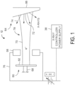
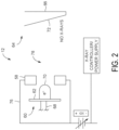
- FIGS. 1 and 2 are schematic illustrations of an embodiment of a portion of an X-ray tube 12 (e.g., having a gridding electrode 58) coupled to an X-ray controller/power supply 38 (e.g., without gridding an electron beam).
- the X-ray tube 12 includes an electron beam source 60 including a cathode 62, an anode assembly 64 including an anode 66, and a gridding electrode 58.
- the cathode 62, anode 66, and the gridding electrode 58 may be disposed within an enclosure (not shown) such as a glass or metallic envelope.
- the X-ray tube 12 may be positioned within a casing (not shown) which may be made of aluminum and lined with lead.
- the anode assembly 64 may include a rotor and a stator (not shown) outside of the X-ray tube 12 at least partially surrounding the rotor for causing rotation of an anode 66 during operation.
- the voltage difference between the cathode 62 and the anode 66 may range from tens of thousands of volts to in excess of hundreds of thousands of volts.
- the anode 66 is coupled to the rotor (not shown) via a shaft (not shown). Rotation of the anode 66 allows the electron beam 70 to constantly strike a different point on the anode perimeter.
- a vacuum of the order of 10 -5 to about 10 -9 torr at room temperature is preferably maintained to permit unperturbed transmission of the electron beam 70 between the cathode 62 and the anode 66.
- the gridding electrode 58 is configured to receive electrical signals via a series of electrical leads 76 that cause the gridding electrode 58 to grid the electron beam 70.
- the electrical signals may be timing/control signals (via the X-ray controller/power supply 38) that cause the gridding electrode 58, when energized or powered to a specific level (e.g., less than +6000 V to -5000 V), to grid the electron beam 70.
- the gridding electrode 58 is disposed about a path 78 of the electron beam 70 between the electron beam source 60 (e.g., cathode 62) and the anode assembly 64 (e.g., anode 66).
- the gridding electrode 58 may be annularly shaped. As depicted in FIG.
- stages may be configured to change the voltage fast, such as sub-micron seconds, control the maximum voltage and/or control the shape of the waveforms used to apply the voltage to the gridding electrode 58.
- the stages may each be configured differently to allow switching at different speeds.
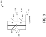
- the switching units 300 may be combined or cascaded, for example, to form a multi-stage switching unit 400 shown in FIG. 4 . It should be noted that like numerals represent like parts. Additionally, while FIG. 4 illustrates two stages, additional stages may be provided as described in more detail herein. It should be noted that for each of the switching units 300, during a particular state of operation, one of the switches 302 or 304 is open and the other switch 304 or 302 is closed.
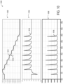
- First output loss diagram 1000 includes a first output voltage graph 1002, where first output voltage graph 1002 includes a first ladder output voltage plot 1010, and a first circuit output voltage plot 1012.
- First ladder output voltage plot 1010 shows a commanded voltage applied to gridding electrode 550 over time during a transition from the bias voltage to the gridding voltage
- first circuit output voltage plot 1012 shows an actual electrode voltage generated at the gridding electrode 550 over the transition as a result of the commanded voltage.
- FIG. 11 shows a second output loss diagram 1100, corresponding to a second embodiment of the first control circuit 502 including the inductor 534.
- Second output loss diagram 1100 includes a second output voltage graph 1102, where second output voltage graph 1102 includes a second ladder output voltage plot 1110, and a second circuit output voltage plot 1112.
- Second ladder output voltage plot 1110 shows a commanded voltage applied to gridding electrode 550 over time during a transition from the bias voltage to the gridding voltage
- second circuit output voltage plot 1112 shows an actual electrode voltage generated at the gridding electrode 550 over the transition as a result of the commanded voltage.
- the second control circuit 504 that controls the bias voltage includes a high precision voltage source 570, a capacitor 571 (e.g., capacitor 321) and various switches, such as switches 562-563.
- Voltage source 570 may be a variable, high precision voltage source capable of supplying between 0 and -1200V via capacitor 571 with a high degree of precision (e.g., +/- 50V).
- a simplified bidirectional flyback may be used for the voltage source 570.
- the second control circuit 504 may generate the bias voltage (or not) by switching either or both of the switches 562 and 563 from a closed position to an open position, or vice versa.
- redundancy may be provided for improved reliability.
- a plurality of low voltage circuit portions may be utilized, with each low voltage circuit portion coupled to a group of voltage control modules and configured to control a voltage provided to the corresponding group of voltage control modules from a given low voltage circuit portion.
- a plurality of transformers may be utilized, with each transformer operably coupled to at least one corresponding voltage control module.
- a given transformer and a corresponding low voltage circuit portion may be coupled to a corresponding low voltage circuit portion.
- the unipolar cathode may be used in modern interventional imaging systems that can be gridded off with a voltage greater than a threshold negative voltage, for example, -8kV, and that rely on a precise controllable bias voltage between a common voltage (e.g., a reference voltage for the circuit, which for simplicity is considered to be 0V herein), and -1.2kV with a precision of +/- 50V to turn on and control the electron beam shape.
- the bias voltage and the gridding voltage are expressed with respect to the common voltage.
- the common voltage may be a high voltage, for example, up to 125kV.
- the common voltage is referred to herein as 0V
- the common voltage in absolute terms may be -125kV
- the gridding voltage of -8kV may be an absolute voltage of -133kV.
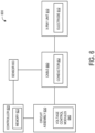
- Method 700 may be executed by a controller or processor of the interventional imaging system, based on instructions stored in a memory of the interventional imaging system.
- Method 700 begins at 702, where method 700 includes receiving a first instruction to switch the unipolar cathode of the interventional imaging system on.
- the first instruction may be an instruction to initiate an X-ray pulse generated by a protocol selected by an operator of the interventional imaging system.
- method 700 includes increasing the electrode voltage supplied to the gridding electrode 550 from the common voltage to the bias voltage (e.g., -1.2 kV with a precision of +/-50V).
- Increasing the electrode voltage supplied to the gridding electrode 550 from the common voltage to the bias voltage may include maintaining the voltage sources of stages 510-517 off.
- the bias voltage may be generated by the second control circuit 504, which may be connected to the gridding electrode 550 by opening switch 563 and closing switch 562.
- the cathode may be switched on, whereby X-rays may be generated by the cathode and the X-ray may be performed.
- method 700 includes decreasing the electrode voltage from the bias voltage to the common voltage. Decreasing the electrode voltage to the common voltage may be accomplished by opening switch 562 and closing switch 563 of the second control circuit, so that no bias voltage generated by the second voltage source is applied to the cathode (e.g., to the gridding electrode 550). Decreasing the electrode voltage to the common voltage from the bias voltage via the second control circuit can be performed quickly and without precision.
- the electrode voltage applied to the gridding electrode 550 to start the X-ray exposure may be generated by the second control circuit, and the electrode voltage applied to the gridding electrode 550 to end the X-ray exposure may be generated by the first control circuit.
- the split of these two functions allows for a decrease in voltage when precision is not required (grid), while allowing suitable voltage precision in a short period of time when the bias voltage is applied to the gridding electrode 550.
- One advantage of splitting the two functions is that the bias voltage generated by the second voltage source 571 of second control circuit 504 may be unaffected by a temporary decrease in voltage at the gridding electrode 550 of the cathode due to parasitic capacitance associated with long cables (e.g., cable 650 of FIG.
- a dashed line 806 indicates a threshold voltage of -5.5kV at which an electron beam may not be generated by the cathode.
- Newer interventional imaging systems may be gridded off with a voltage of -8kV or less, as indicated by a dashed line 808.
- the first voltage at which the cathode is gridded off is -8kV, as indicated by a dashed line 810.
- a X-ray exposure may be initiated via the interventional imaging system.
- the X-ray exposure may be initiated in accordance with a protocol executed by the interventional imaging system based on input from an operator of the interventional imaging system.
- instructions are supplied to a controller of the interventional imaging system, that when executed, actuate one or more switches of the multi-stage circuit to decrease the electrode voltage (in a negative direction) to a common voltage of the interventional imaging system, as indicated by plot 802.
- the common voltage is considered to be 0V.
- the electrode voltage has increased to -7.1kV, achieving the threshold voltage relied on by the newer interventional imaging systems for gridding off.
- the interventional imaging system is no longer generating X-rays, having past the threshold for generating the electron beam indicated by dashed line 806, and the patient is not exposed to the radiation.
- the electrode voltage slowly increases (in the negative direction) to achieve the first voltage, at which in this embodiment the cathode is gridded off.
- a second transition from the second bias voltage to the first gridding voltage may be performed in two steps, a first step where the electrode voltage is decreased to the common voltage (by connecting to the common voltage, where precise control of the voltage transition is not an issue), and a second step where the electrode voltage is increased to the first gridding voltage.
- one or both switches of third stage 512 are opened or closed to switch off a corresponding 1kV voltage source 520, thereby decreasing the amount of negative voltage to -5kV, and so on, until the time t4, when all of the 1kV voltage sources 520 of all of stages 510-517 are switched off, and the electrode voltage is the common voltage.
- the bias voltage shown by line 906 may be generated by the second control circuit 504 of multi-stage switching unit 500.
- switches 562-563 of multi-stage switching unit 500 may be actuated to generate the bias voltage via the second high precision voltage source 570.
- a first total time 920 taken by the multi-stage circuit to achieve the bias voltage is the time between time t1 and time t4.
- a second, dashed line 908 shows an alternative transition from the first gridding voltage directly to the bias voltage using the multi-stage circuit with the architecture disclosed herein.
- This alternative transition even if it has some advantages, is less repeatable (more dependent on circuit (components tolerance) and environment (cable length) variability) and includes simultaneous transitions of the flyback stage and of the 1kV stages (involving additional perturbation on bias voltage and needing more complex control).
- a second alternative transition from the first gridding voltage directly to the bias voltage may be performed using an alternative circuit with a different architecture and without using the multi-stage circuit with the architecture disclosed herein, but with higher constraints on the electronic components.
- the technical effect of controlling an electrode voltage of an interventional imaging system to the common voltage during transitioning between a gridding voltage of the interventional imaging system and a bias voltage of the interventional imaging system is that an effect of a temporary decrease in a voltage generated at a cathode of the interventional imaging system during the transition may be reduced, creating a more stable system with a lower probability of component damage.
- the disclosure also provides support for a method for an interventional imaging system, the method comprising: applying a voltage to a gridding electrode of a cathode of the interventional imaging system, controlling a first transition of the voltage from a first, gridding voltage of the interventional imaging system to a second, bias voltage of the interventional imaging system to perform an X-ray exposure using the interventional imaging system, by decreasing the voltage from the first, gridding voltage to a common voltage of the interventional imaging system, and increasing the voltage from the common voltage to the second, bias voltage, and controlling a second transition of the voltage from the second, bias voltage to the first, gridding voltage to stop performing the X-ray exposure by decreasing the voltage from the second, bias voltage to the common voltage, and increasing the voltage from the common voltage to the first, gridding voltage.
- the disclosure also provides support for an interventional imaging system, comprising: an X-ray source including a cathode, a plurality of voltage sources configured to supply a voltage to a gridding electrode of the cathode, a first control circuit configured to generate a first, gridding voltage to the gridding electrode, a second control circuit configured to generate a second, bias voltage to the gridding electrode, and a controller operably connected to the X-ray source and configured to: in response to receiving an instruction to switch the cathode of the X-ray source on, decrease the voltage applied to the gridding electrode from the first, gridding voltage to a common voltage of the interventional imaging system in a first step using the first control circuit, and increase the voltage from the common voltage to the second, bias voltage in a second step using the second control circuit, and in response to receiving an instruction to switch the cathode off, decrease the voltage from the second, bias voltage to the common voltage in a first step using the second control circuit, and increase the voltage from the common voltage to
- the second control circuit comprises a variable high precision voltage source capable of delivering up to -1.2kV with respect to the common voltage.
- a total voltage supplied by the first control circuit and the second control circuit is a gridding voltage of -8kV with respect to the common voltage.
- a seventh example of the system optionally including one or more or each of the first through sixth examples,: in a first condition when the cathode is switched on, the second, bias voltage is applied to the gridding electrode by the second control circuit, and no voltage is applied to the gridding electrode by the first control circuit, and in a second condition when the cathode is switched off, the first gridding voltage is applied to the gridding electrode by the first control circuit, and no voltage is applied to the gridding electrode by the second control circuit.
- the disclosure also provides support for a method for an interventional imaging system, the method comprising: in response to receiving an instruction to switch on a cathode of the interventional imaging system: decreasing a voltage supplied to a gridding electrode of the cathode from a first, gridding voltage of the interventional imaging system to a common voltage of the interventional imaging system, and increasing the voltage from the common voltage to a second, bias voltage of the interventional imaging system, and in response to receiving an instruction to switch the cathode off: decreasing the voltage from the second, bias voltage to the common voltage, and increasing the voltage from the common voltage to the first, gridding voltage, wherein: a first control circuit of a multi-stage switching unit of the interventional imaging system is used to decrease the voltage from the first, gridding voltage to the common voltage and to increase the voltage from the common voltage to the first, gridding voltage, and a second control circuit of the multi-stage switching unit of the interventional imaging system is used to increase the voltage from the common voltage to the second, bias voltage and to decrease the
- the cathode is a unipolar cathode, and both of the first, gridding voltage and the second, bias voltage are negative voltages.
- a first total amount of time taken to decrease the voltage from the first, gridding voltage to the common voltage and increase the voltage from the common voltage to the second, bias voltage is less than 50us
- a second total amount of time taken to decrease the second, bias voltage to the common voltage is less than 50us.
- the articles “a,” “an,” and “the” are intended to mean that there are one or more of the elements.
- the terms “comprising,” “including,” and “having” are intended to be inclusive and mean that there may be additional elements other than the listed elements.
- one object e.g., a material, element, structure, member, etc.
- references to “one embodiment” or “an embodiment” of the present disclosure are not intended to be interpreted as excluding the existence of additional embodiments that also incorporate the recited features.
Landscapes
- X-Ray Techniques (AREA)
Applications Claiming Priority (1)
| Application Number | Priority Date | Filing Date | Title |
|---|---|---|---|
| US18/484,277 US12382569B2 (en) | 2023-10-10 | 2023-10-10 | Remote control of cathode width voltage |
Publications (2)
| Publication Number | Publication Date |
|---|---|
| EP4539610A2 true EP4539610A2 (de) | 2025-04-16 |
| EP4539610A3 EP4539610A3 (de) | 2025-07-16 |
Family
ID=92909572
Family Applications (1)
| Application Number | Title | Priority Date | Filing Date |
|---|---|---|---|
| EP24202511.2A Pending EP4539610A3 (de) | 2023-10-10 | 2024-09-25 | Steuerung der gitterspannung |
Country Status (3)
| Country | Link |
|---|---|
| US (1) | US12382569B2 (de) |
| EP (1) | EP4539610A3 (de) |
| CN (1) | CN119815657A (de) |
Families Citing this family (1)
| Publication number | Priority date | Publication date | Assignee | Title |
|---|---|---|---|---|
| US12557202B2 (en) * | 2023-10-10 | 2026-02-17 | GE Precision Healthcare LLC | Strategy for controlling cathode width voltage |
Family Cites Families (8)
| Publication number | Priority date | Publication date | Assignee | Title |
|---|---|---|---|---|
| US5388139A (en) * | 1989-12-07 | 1995-02-07 | Electromed International | High-voltage power supply and regulator circuit for an X-ray tube with closed-loop feedback for controlling X-ray exposure |
| JP4889871B2 (ja) | 2001-03-29 | 2012-03-07 | 浜松ホトニクス株式会社 | X線発生装置 |
| JP2004139790A (ja) * | 2002-10-16 | 2004-05-13 | Toshiba Corp | X線管装置 |
| US7792241B2 (en) * | 2008-10-24 | 2010-09-07 | General Electric Company | System and method of fast KVP switching for dual energy CT |
| US9253864B2 (en) * | 2013-08-30 | 2016-02-02 | General Electric Company | Apparatus and methods to control an electron beam of an X-ray tube |
| US9438120B2 (en) * | 2014-01-22 | 2016-09-06 | General Electric Company | Systems and methods for fast kilovolt switching in an X-ray system |
| US10262829B2 (en) | 2015-12-14 | 2019-04-16 | General Electric Company | Protection circuit assembly and method for high voltage systems |
| JP7008598B2 (ja) * | 2017-09-07 | 2022-01-25 | 日本電子株式会社 | 電子銃および電子線装置 |
-
2023
- 2023-10-10 US US18/484,277 patent/US12382569B2/en active Active
-
2024
- 2024-09-25 EP EP24202511.2A patent/EP4539610A3/de active Pending
- 2024-09-26 CN CN202411353311.6A patent/CN119815657A/zh active Pending
Also Published As
| Publication number | Publication date |
|---|---|
| CN119815657A (zh) | 2025-04-11 |
| US20250120003A1 (en) | 2025-04-10 |
| US12382569B2 (en) | 2025-08-05 |
| EP4539610A3 (de) | 2025-07-16 |
Similar Documents
| Publication | Publication Date | Title |
|---|---|---|
| US9253864B2 (en) | Apparatus and methods to control an electron beam of an X-ray tube | |
| US9412552B2 (en) | Multi-source radiation generating apparatus and radiographic imaging system | |
| CN104918554B (zh) | 用于x射线系统中的快速千伏切换的系统和方法 | |
| US8712015B2 (en) | Electron beam manipulation system and method in X-ray sources | |
| EP4539610A2 (de) | Steuerung der gitterspannung | |
| RU2576669C2 (ru) | Блок электропитания для рентгеновской трубки | |
| US9856722B2 (en) | Methods and systems for controlling voltage switching | |
| EP4539609A1 (de) | Strategie zur steuerung einer gitterspannung | |
| CN117479405A (zh) | 具有栅极电压单元的x射线源 | |
| CN115410883A (zh) | 一种高压发生器 | |
| CN115793765B (zh) | 一种有源电流控制电路 | |
| US12058800B2 (en) | CNT X-ray tube control system with dummy load | |
| US7215739B2 (en) | Active dose reduction device and method | |
| US11690158B2 (en) | Controlling an x-ray tube | |
| Behling | X-ray generators | |
| EP3134963B1 (de) | Resonanzwandler, hochspannungsgenerator und röntgenröhre mit dem resonanzwandler und verfahren zur steuerung eines resonanzwandlers | |
| CN109922589B (zh) | 用于向负载提供电功率的系统和方法 | |
| KR102781943B1 (ko) | 멀티 엑스선 소스 구동장치 및 이를 이용한 엑스선 발생장치 | |
| JP3714704B2 (ja) | X線画像増強管を使用する方法およびその方法を実現する回路 | |
| JP2001230098A (ja) | 高電圧スイッチ回路及びこれを用いたx線高電圧装置 | |
| EP4344358A1 (de) | Röntgenquellenanordnung mit mehreren filamenten | |
| KR102781945B1 (ko) | 엑스선 소스의 구동장치 및 이를 이용한 엑스선 발생장치 | |
| US8781074B2 (en) | Discharge module for high voltage x-ray tubes | |
| EP4120801A1 (de) | Röntgenbildgebung mit schneller kvp-umschaltung | |
| JP2011167466A (ja) | X線ct装置 |
Legal Events
| Date | Code | Title | Description |
|---|---|---|---|
| PUAI | Public reference made under article 153(3) epc to a published international application that has entered the european phase |
Free format text: ORIGINAL CODE: 0009012 |
|
| STAA | Information on the status of an ep patent application or granted ep patent |
Free format text: STATUS: REQUEST FOR EXAMINATION WAS MADE |
|
| 17P | Request for examination filed |
Effective date: 20240925 |
|
| AK | Designated contracting states |
Kind code of ref document: A2 Designated state(s): AL AT BE BG CH CY CZ DE DK EE ES FI FR GB GR HR HU IE IS IT LI LT LU LV MC ME MK MT NL NO PL PT RO RS SE SI SK SM TR |
|
| PUAL | Search report despatched |
Free format text: ORIGINAL CODE: 0009013 |
|
| AK | Designated contracting states |
Kind code of ref document: A3 Designated state(s): AL AT BE BG CH CY CZ DE DK EE ES FI FR GB GR HR HU IE IS IT LI LT LU LV MC ME MK MT NL NO PL PT RO RS SE SI SK SM TR |
|
| RIC1 | Information provided on ipc code assigned before grant |
Ipc: H05G 1/08 20060101AFI20250612BHEP Ipc: H05G 1/56 20060101ALI20250612BHEP Ipc: H05G 1/58 20060101ALI20250612BHEP |