EP4539264A2 - Abgewinkelte baugruppe für einen abgewinkelten verbinder - Google Patents
Abgewinkelte baugruppe für einen abgewinkelten verbinder Download PDFInfo
- Publication number
- EP4539264A2 EP4539264A2 EP25160243.9A EP25160243A EP4539264A2 EP 4539264 A2 EP4539264 A2 EP 4539264A2 EP 25160243 A EP25160243 A EP 25160243A EP 4539264 A2 EP4539264 A2 EP 4539264A2
- Authority
- EP
- European Patent Office
- Prior art keywords
- shield
- angled
- section
- dielectric
- cable
- Prior art date
- Legal status (The legal status is an assumption and is not a legal conclusion. Google has not performed a legal analysis and makes no representation as to the accuracy of the status listed.)
- Pending
Links
Images




Classifications
-
- H—ELECTRICITY
- H01—ELECTRIC ELEMENTS
- H01R—ELECTRICALLY-CONDUCTIVE CONNECTIONS; STRUCTURAL ASSOCIATIONS OF A PLURALITY OF MUTUALLY-INSULATED ELECTRICAL CONNECTING ELEMENTS; COUPLING DEVICES; CURRENT COLLECTORS
- H01R13/00—Details of coupling devices of the kinds covered by groups H01R12/70 or H01R24/00 - H01R33/00
- H01R13/648—Protective earth or shield arrangements on coupling devices, e.g. anti-static shielding
- H01R13/658—High frequency shielding arrangements, e.g. against EMI [Electro-Magnetic Interference] or EMP [Electro-Magnetic Pulse]
- H01R13/6591—Specific features or arrangements of connection of shield to conductive members
- H01R13/6592—Specific features or arrangements of connection of shield to conductive members the conductive member being a shielded cable
- H01R13/6593—Specific features or arrangements of connection of shield to conductive members the conductive member being a shielded cable the shield being composed of different pieces
-
- H—ELECTRICITY
- H01—ELECTRIC ELEMENTS
- H01R—ELECTRICALLY-CONDUCTIVE CONNECTIONS; STRUCTURAL ASSOCIATIONS OF A PLURALITY OF MUTUALLY-INSULATED ELECTRICAL CONNECTING ELEMENTS; COUPLING DEVICES; CURRENT COLLECTORS
- H01R13/00—Details of coupling devices of the kinds covered by groups H01R12/70 or H01R24/00 - H01R33/00
- H01R13/46—Bases; Cases
- H01R13/50—Bases; Cases formed as an integral body
- H01R13/501—Bases; Cases formed as an integral body comprising an integral hinge or a frangible part
-
- H—ELECTRICITY
- H01—ELECTRIC ELEMENTS
- H01R—ELECTRICALLY-CONDUCTIVE CONNECTIONS; STRUCTURAL ASSOCIATIONS OF A PLURALITY OF MUTUALLY-INSULATED ELECTRICAL CONNECTING ELEMENTS; COUPLING DEVICES; CURRENT COLLECTORS
- H01R13/00—Details of coupling devices of the kinds covered by groups H01R12/70 or H01R24/00 - H01R33/00
- H01R13/648—Protective earth or shield arrangements on coupling devices, e.g. anti-static shielding
- H01R13/658—High frequency shielding arrangements, e.g. against EMI [Electro-Magnetic Interference] or EMP [Electro-Magnetic Pulse]
- H01R13/6581—Shield structure
-
- H—ELECTRICITY
- H01—ELECTRIC ELEMENTS
- H01R—ELECTRICALLY-CONDUCTIVE CONNECTIONS; STRUCTURAL ASSOCIATIONS OF A PLURALITY OF MUTUALLY-INSULATED ELECTRICAL CONNECTING ELEMENTS; COUPLING DEVICES; CURRENT COLLECTORS
- H01R13/00—Details of coupling devices of the kinds covered by groups H01R12/70 or H01R24/00 - H01R33/00
- H01R13/648—Protective earth or shield arrangements on coupling devices, e.g. anti-static shielding
- H01R13/658—High frequency shielding arrangements, e.g. against EMI [Electro-Magnetic Interference] or EMP [Electro-Magnetic Pulse]
- H01R13/6591—Specific features or arrangements of connection of shield to conductive members
- H01R13/65912—Specific features or arrangements of connection of shield to conductive members for shielded multiconductor cable
- H01R13/65914—Connection of shield to additional grounding conductors
-
- H—ELECTRICITY
- H01—ELECTRIC ELEMENTS
- H01R—ELECTRICALLY-CONDUCTIVE CONNECTIONS; STRUCTURAL ASSOCIATIONS OF A PLURALITY OF MUTUALLY-INSULATED ELECTRICAL CONNECTING ELEMENTS; COUPLING DEVICES; CURRENT COLLECTORS
- H01R13/00—Details of coupling devices of the kinds covered by groups H01R12/70 or H01R24/00 - H01R33/00
- H01R13/648—Protective earth or shield arrangements on coupling devices, e.g. anti-static shielding
- H01R13/658—High frequency shielding arrangements, e.g. against EMI [Electro-Magnetic Interference] or EMP [Electro-Magnetic Pulse]
- H01R13/6591—Specific features or arrangements of connection of shield to conductive members
- H01R13/65912—Specific features or arrangements of connection of shield to conductive members for shielded multiconductor cable
- H01R13/65915—Twisted pair of conductors surrounded by shield
-
- H—ELECTRICITY
- H01—ELECTRIC ELEMENTS
- H01R—ELECTRICALLY-CONDUCTIVE CONNECTIONS; STRUCTURAL ASSOCIATIONS OF A PLURALITY OF MUTUALLY-INSULATED ELECTRICAL CONNECTING ELEMENTS; COUPLING DEVICES; CURRENT COLLECTORS
- H01R4/00—Electrically-conductive connections between two or more conductive members in direct contact, i.e. touching one another; Means for effecting or maintaining such contact; Electrically-conductive connections having two or more spaced connecting locations for conductors and using contact members penetrating insulation
- H01R4/10—Electrically-conductive connections between two or more conductive members in direct contact, i.e. touching one another; Means for effecting or maintaining such contact; Electrically-conductive connections having two or more spaced connecting locations for conductors and using contact members penetrating insulation effected solely by twisting, wrapping, bending, crimping, or other permanent deformation
- H01R4/18—Electrically-conductive connections between two or more conductive members in direct contact, i.e. touching one another; Means for effecting or maintaining such contact; Electrically-conductive connections having two or more spaced connecting locations for conductors and using contact members penetrating insulation effected solely by twisting, wrapping, bending, crimping, or other permanent deformation by crimping
-
- H—ELECTRICITY
- H01—ELECTRIC ELEMENTS
- H01R—ELECTRICALLY-CONDUCTIVE CONNECTIONS; STRUCTURAL ASSOCIATIONS OF A PLURALITY OF MUTUALLY-INSULATED ELECTRICAL CONNECTING ELEMENTS; COUPLING DEVICES; CURRENT COLLECTORS
- H01R43/00—Apparatus or processes specially adapted for manufacturing, assembling, maintaining, or repairing of line connectors or current collectors or for joining electric conductors
- H01R43/04—Apparatus or processes specially adapted for manufacturing, assembling, maintaining, or repairing of line connectors or current collectors or for joining electric conductors for forming connections by deformation, e.g. crimping tool
- H01R43/048—Crimping apparatus or processes
-
- H—ELECTRICITY
- H01—ELECTRIC ELEMENTS
- H01R—ELECTRICALLY-CONDUCTIVE CONNECTIONS; STRUCTURAL ASSOCIATIONS OF A PLURALITY OF MUTUALLY-INSULATED ELECTRICAL CONNECTING ELEMENTS; COUPLING DEVICES; CURRENT COLLECTORS
- H01R9/00—Structural associations of a plurality of mutually-insulated electrical connecting elements, e.g. terminal strips or terminal blocks; Terminals or binding posts mounted upon a base or in a case; Bases therefor
- H01R9/03—Connectors arranged to contact a plurality of the conductors of a multiconductor cable, e.g. tapping connections
- H01R9/05—Connectors arranged to contact a plurality of the conductors of a multiconductor cable, e.g. tapping connections for coaxial cables
- H01R9/0518—Connection to outer conductor by crimping or by crimping ferrule
-
- H—ELECTRICITY
- H01—ELECTRIC ELEMENTS
- H01R—ELECTRICALLY-CONDUCTIVE CONNECTIONS; STRUCTURAL ASSOCIATIONS OF A PLURALITY OF MUTUALLY-INSULATED ELECTRICAL CONNECTING ELEMENTS; COUPLING DEVICES; CURRENT COLLECTORS
- H01R13/00—Details of coupling devices of the kinds covered by groups H01R12/70 or H01R24/00 - H01R33/00
- H01R13/648—Protective earth or shield arrangements on coupling devices, e.g. anti-static shielding
- H01R13/658—High frequency shielding arrangements, e.g. against EMI [Electro-Magnetic Interference] or EMP [Electro-Magnetic Pulse]
- H01R13/6581—Shield structure
- H01R13/6582—Shield structure with resilient means for engaging mating connector
-
- H—ELECTRICITY
- H01—ELECTRIC ELEMENTS
- H01R—ELECTRICALLY-CONDUCTIVE CONNECTIONS; STRUCTURAL ASSOCIATIONS OF A PLURALITY OF MUTUALLY-INSULATED ELECTRICAL CONNECTING ELEMENTS; COUPLING DEVICES; CURRENT COLLECTORS
- H01R4/00—Electrically-conductive connections between two or more conductive members in direct contact, i.e. touching one another; Means for effecting or maintaining such contact; Electrically-conductive connections having two or more spaced connecting locations for conductors and using contact members penetrating insulation
- H01R4/10—Electrically-conductive connections between two or more conductive members in direct contact, i.e. touching one another; Means for effecting or maintaining such contact; Electrically-conductive connections having two or more spaced connecting locations for conductors and using contact members penetrating insulation effected solely by twisting, wrapping, bending, crimping, or other permanent deformation
- H01R4/18—Electrically-conductive connections between two or more conductive members in direct contact, i.e. touching one another; Means for effecting or maintaining such contact; Electrically-conductive connections having two or more spaced connecting locations for conductors and using contact members penetrating insulation effected solely by twisting, wrapping, bending, crimping, or other permanent deformation by crimping
- H01R4/183—Electrically-conductive connections between two or more conductive members in direct contact, i.e. touching one another; Means for effecting or maintaining such contact; Electrically-conductive connections having two or more spaced connecting locations for conductors and using contact members penetrating insulation effected solely by twisting, wrapping, bending, crimping, or other permanent deformation by crimping for cylindrical elongated bodies, e.g. cables having circular cross-section
- H01R4/184—Electrically-conductive connections between two or more conductive members in direct contact, i.e. touching one another; Means for effecting or maintaining such contact; Electrically-conductive connections having two or more spaced connecting locations for conductors and using contact members penetrating insulation effected solely by twisting, wrapping, bending, crimping, or other permanent deformation by crimping for cylindrical elongated bodies, e.g. cables having circular cross-section comprising a U-shaped wire-receiving portion
- H01R4/185—Electrically-conductive connections between two or more conductive members in direct contact, i.e. touching one another; Means for effecting or maintaining such contact; Electrically-conductive connections having two or more spaced connecting locations for conductors and using contact members penetrating insulation effected solely by twisting, wrapping, bending, crimping, or other permanent deformation by crimping for cylindrical elongated bodies, e.g. cables having circular cross-section comprising a U-shaped wire-receiving portion combined with a U-shaped insulation-receiving portion
-
- H—ELECTRICITY
- H01—ELECTRIC ELEMENTS
- H01R—ELECTRICALLY-CONDUCTIVE CONNECTIONS; STRUCTURAL ASSOCIATIONS OF A PLURALITY OF MUTUALLY-INSULATED ELECTRICAL CONNECTING ELEMENTS; COUPLING DEVICES; CURRENT COLLECTORS
- H01R4/00—Electrically-conductive connections between two or more conductive members in direct contact, i.e. touching one another; Means for effecting or maintaining such contact; Electrically-conductive connections having two or more spaced connecting locations for conductors and using contact members penetrating insulation
- H01R4/10—Electrically-conductive connections between two or more conductive members in direct contact, i.e. touching one another; Means for effecting or maintaining such contact; Electrically-conductive connections having two or more spaced connecting locations for conductors and using contact members penetrating insulation effected solely by twisting, wrapping, bending, crimping, or other permanent deformation
- H01R4/18—Electrically-conductive connections between two or more conductive members in direct contact, i.e. touching one another; Means for effecting or maintaining such contact; Electrically-conductive connections having two or more spaced connecting locations for conductors and using contact members penetrating insulation effected solely by twisting, wrapping, bending, crimping, or other permanent deformation by crimping
- H01R4/20—Electrically-conductive connections between two or more conductive members in direct contact, i.e. touching one another; Means for effecting or maintaining such contact; Electrically-conductive connections having two or more spaced connecting locations for conductors and using contact members penetrating insulation effected solely by twisting, wrapping, bending, crimping, or other permanent deformation by crimping using a crimping sleeve
Definitions
- the present invention relates to a subassembly of a connector and, more particularly, to an angled subassembly for an angled connector.
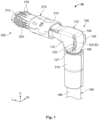
- the second shield section 130 extends at a bend angle 140 with respect to the first shield section 120.
- the bend angle 140 is 90° and the second shield section 130 extends perpendicularly with respect to the first shield section 120.
- the bend angle 140 can be any angle greater than 90° and less than 180°, and the second shield section 130 can extend at angles between 90° and 180° with respect to the first shield section 120.
- the bend angle 140 can be less than 90° or equal to 180°.
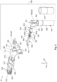
- the angled shield 110 has a shield cover 124 attached to the shield body 112 at a shield hinge 128.
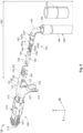
- the shield cover 124 is pivotable with respect to the shield body 112 about the shield hinge 128 between an open shield position SO, shown in Figure 2 , and a closed shield position SC, as shown in Figure 3 .
- the shield body 112 has a tab 123 in the first shield section 120 and the shield cover 124 has a recess 126 extending into the shield cover 124.
- the tab 123 enters the recess 126 and secures the shield cover 124 in the closed shield position SC.
- the shield body 112 has two tabs 123 corresponding to two recesses 126 of the shield cover 124.
- the shield body 112 may have one or more than two tabs 123 and the shield cover 124 may have one or more than two recesses 126, provided that the number of tabs 123 is equal to the number of recesses 126.
- the shield body 112 has a shield latch 127 extending from the shield body 112 in the first shield section 120.
- the shield cover 124 has a shield catch 125 extending from the shield cover 124. When the shield cover 124 is pivoted into the closed shield position SC, as shown in Figure 3 , the shield catch 125 engages with the shield latch 127 to secure the shield cover 124 in the closed shield position SC.
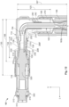
- the angled shield 110 has a transition portion 134 in which a dimension of an interior space 138 of the second shield section 130, shown in Figures 7 and 8 , is decreased along the vertical direction V and a width direction W perpendicular to the longitudinal direction L and the vertical direction V.
- the transition portion 134 is formed by a plurality of spring members 136 extending into the interior space 138 of the second shield section 130 opposite one another in the vertical direction V.
- two spring members 136 are positioned opposite one another in the vertical direction V and two spring members 136 are positioned opposite one another in the width direction W.
- the transition portion 134 may include three or less or five or more spring members 136.
- Each of the spring members 136 is resiliently deflectable and has a contact bend 137 at a maximum protrusion into the interior space 138.
- the cable 180 includes a twisted pair of wires 183, with each of the wires 183 having a conductor 183a and a wire insulation 183b disposed around the conductor 183a.
- the wires 183 are twisted around one another within the foil 184 with the wire insulation 183b of each of the wires 183 in abutment with one another.
- the cable 180 includes a pair of wires 183 extending parallel to one another, each of the wires 183 having the conductor 183a and the wire insulation 183b.
- the cable 180 may have one wire 183 with one conductor 183a surrounded by one wire insulation 183b.
- the contact 190 has a mating portion 192 and a connection portion 194 at an end opposite the mating portion 192.
- the contact 190 is formed of a conductive material.
- the mating portion 192 is a receptacle for a pin; in other embodiments, the mating portion 192 could be a pin or any other type of contact element capable of mating with another contact element.
- the connection portion 194 is a crimping portion capable of being crimped to a conductor. In other embodiments, the connection portion 194 could be a flat element capable of being welded to a conductor, or any other type of element capable of mechanically and electrically connecting the contact 190 to a conductor.
- the inner ferrule 200 has a base 210 extending from a first end 212 to a second end 214 along the longitudinal direction L.
- the inner ferrule 200 has a first crimp section 220 at the first end 212 and a second crimp section 230 at the second end 214; the second crimp section 230 is connected to the first crimp section 220 by the base 210.
- the first crimp section 220 has a pair of first crimp wings 222 extending from the base 210 and positioned opposite one another in the width direction W.
- the second crimp section 220 has a pair of second crimp wings 232 extending from the base 210 and positioned opposite one another in the width direction W.
- the braid 185 in the first portion 187 is crimped to the first shield section 120 by the outer ferrule 210 and is disposed between the first shield section 120 and the outer ferrule 210; in an embodiment, the first shield section 120 provides a support for crimping of the outer ferrule 210 around the braid 185 and the cable 180 that prevents the crimping of the outer ferrule 210 from damaging the foil 194 or the wires 183.
- the contact springs 316 of the mating shield 310 resiliently abut and electrically connect with a shield of the mating connector, and the contacts 190 mate and electrically connect with contacts of the mating connector.
- the inner ferrule 200' has a base 210 extending from a first end 212 to a second end 214 along the longitudinal direction L.
- the inner ferrule 200' has a third crimp section 240 at the first end 212, a second crimp section 230 at the second end 214, and a first crimp section 220 between the third crimp section 240 and the second crimp section 230; the third crimp section 240 is connected to the first crimp section 220 and the second crimp section 230 by the base 210.
- the first crimp section 220 has a pair of first crimp wings 222 extending from the base 210 and positioned opposite one another in the width direction W.
- the first end 212 of the base 210 is connected to a carrier strip 240.
- a plurality of inner ferrules 200' can be connected to the carrier strip 240 to move the inner ferrules 200' during production or for other applications and, prior to use of the inner ferrule 200' as described below, the inner ferrule 200' is separated from the carrier strip 240 at the first end 212 of the base 210.
- the inner ferrule 200' is formed of a conductive material, such as aluminum or copper, and in an embodiment is monolithically formed in a single piece with at least the base 210, the first crimp section 220, the second crimp section 230, and the third crimp section 240. In the shown embodiment, the inner ferrule 200' is also monolithically formed with the carrier strip 240 prior to separation from the carrier strip 240.
- the inner ferrule 200' may be formed by stamping and bending from a sheet of conductive material. In other embodiments, the inner ferrule 200' may be formed from a plurality of separate elements attached together.
- the inner ferrule 200' is moved into a position in which it is disposed around the cable 180, as shown in Figure 11A .
- the first crimp section 220 and the second crimp section 230 are positioned on the cable 180 and crimped as described above with respect to Figure 6B .
- the third crimp section 140 is disposed around the foil 184 and the wires 183 at a position spaced apart from the first crimp section 220 and the second crimp section 230 along the longitudinal direction L.
- the first crimp section 220 and the second crimp section 230 are crimped, while the third crimp wings 242 of the third crimp section 240 remain uncrimped.
- the bending and crimping of the third crimp section 240 bends the cable 180 to the bend angle 140.
- the third crimp section 240 can be crimped before the bend region 216 is bent and/or crimped such that the third crimp wings 242 do not primarily hold the foil 184 in place and electrically connect the inner ferrule 200' to the foil 184, but rather provide rough positioning and strain relief.
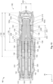
- the angled connector 10' is shown in a fully assembled state in Figures 12 and 13 in which the cable 180 is disposed and held within the angled shield 110. Only the position of the elements of the inner ferrule 200' will be described in detail with respect to Figures 12 and 13 ; the positioning and function of the other elements of the angled connector 10' is the same as described above with respect to Figures 7 and 8 .
Landscapes
- Engineering & Computer Science (AREA)
- Manufacturing & Machinery (AREA)
- Details Of Connecting Devices For Male And Female Coupling (AREA)
Applications Claiming Priority (3)
| Application Number | Priority Date | Filing Date | Title |
|---|---|---|---|
| US17/708,891 US12322909B2 (en) | 2022-03-30 | 2022-03-30 | Angled subassembly for an angled connector |
| PCT/US2023/016987 WO2023192533A1 (en) | 2022-03-30 | 2023-03-30 | Angled subassembly for an angled connector and method of assembling thereof |
| EP23719185.3A EP4500642A1 (de) | 2022-03-30 | 2023-03-30 | Abgewinkelte baugruppe für einen abgewinkelten verbinder und verfahren zur montage davon |
Related Parent Applications (1)
| Application Number | Title | Priority Date | Filing Date |
|---|---|---|---|
| EP23719185.3A Division EP4500642A1 (de) | 2022-03-30 | 2023-03-30 | Abgewinkelte baugruppe für einen abgewinkelten verbinder und verfahren zur montage davon |
Publications (2)
| Publication Number | Publication Date |
|---|---|
| EP4539264A2 true EP4539264A2 (de) | 2025-04-16 |
| EP4539264A3 EP4539264A3 (de) | 2025-06-25 |
Family
ID=86142743
Family Applications (2)
| Application Number | Title | Priority Date | Filing Date |
|---|---|---|---|
| EP25160243.9A Pending EP4539264A3 (de) | 2022-03-30 | 2023-03-30 | Abgewinkelte baugruppe für einen abgewinkelten verbinder |
| EP23719185.3A Pending EP4500642A1 (de) | 2022-03-30 | 2023-03-30 | Abgewinkelte baugruppe für einen abgewinkelten verbinder und verfahren zur montage davon |
Family Applications After (1)
| Application Number | Title | Priority Date | Filing Date |
|---|---|---|---|
| EP23719185.3A Pending EP4500642A1 (de) | 2022-03-30 | 2023-03-30 | Abgewinkelte baugruppe für einen abgewinkelten verbinder und verfahren zur montage davon |
Country Status (7)
| Country | Link |
|---|---|
| US (1) | US12322909B2 (de) |
| EP (2) | EP4539264A3 (de) |
| JP (1) | JP2025510887A (de) |
| KR (1) | KR20240163171A (de) |
| CN (1) | CN119234359A (de) |
| MX (1) | MX2024011929A (de) |
| WO (1) | WO2023192533A1 (de) |
Families Citing this family (6)
| Publication number | Priority date | Publication date | Assignee | Title |
|---|---|---|---|---|
| PH12022551242A1 (en) * | 2019-11-01 | 2023-09-11 | Tyco Electronics Japan G K | Cable connector assembly |
| DE102020117663A1 (de) * | 2020-07-03 | 2022-01-05 | Rosenberger Hochfrequenztechnik Gmbh & Co. Kg | Außenleiterkontaktelement, Winkelsteckverbinder und Verfahren zur Herstellung eines Winkelsteckverbinders |
| CN218602858U (zh) * | 2022-10-17 | 2023-03-10 | 深圳亚力盛连接器有限公司 | 一种h-mtd公端连接器的环形弹片结构 |
| EP4629450A1 (de) * | 2024-04-03 | 2025-10-08 | J.S.T. Mfg. Co., Ltd. | Abgeschirmter verbinder |
| EP4693764A1 (de) * | 2024-08-07 | 2026-02-11 | Aptiv Technologies AG | Abgeschirmte verbinderanordnung für gebogene leiter |
| WO2026059651A1 (en) * | 2024-09-12 | 2026-03-19 | KYOCERA AVX Components Corporation | Low-profile connector |
Family Cites Families (33)
| Publication number | Priority date | Publication date | Assignee | Title |
|---|---|---|---|---|
| US4173386A (en) * | 1978-03-13 | 1979-11-06 | W. L. Gore & Associates, Inc. | Coaxial assembly |
| JPH0526706Y2 (de) * | 1989-11-07 | 1993-07-06 | ||
| JP3016041B2 (ja) | 1990-12-10 | 2000-03-06 | 日本エー・エム・ピー株式会社 | シールド型ツイストケーブルの接続装置 |
| JP2504704B2 (ja) * | 1991-03-12 | 1996-06-05 | ヒロセ電機株式会社 | 同軸ケ―ブル用コネクタと結線方法 |
| US5362255A (en) * | 1993-09-14 | 1994-11-08 | Itt Corporation | Coaxial connector |
| JP3120692B2 (ja) * | 1995-04-18 | 2000-12-25 | 株式会社村田製作所 | 同軸コネクタ |
| DE60313538T2 (de) * | 2002-07-02 | 2008-01-10 | Tyco Electronics Amp Gmbh | Koaxialer Winkelsteckverbinder |
| DE102004029300B4 (de) * | 2003-06-25 | 2024-10-17 | Te Connectivity Germany Gmbh | Koaxial-Steckverbinder |
| JP2006004820A (ja) * | 2004-06-18 | 2006-01-05 | Yazaki Corp | 同軸ケーブル用シールド端子 |
| DE102006012194A1 (de) * | 2006-03-16 | 2007-09-20 | Escha Bauelemente Gmbh | Geschirmter Steckverbinder und Verfahren zu seiner Herstellung |
| US20090075528A1 (en) * | 2007-09-17 | 2009-03-19 | Thomas & Betts International, Inc. | 90-Degree ferrule and pin terminals |
| FR2947961B1 (fr) * | 2009-07-07 | 2012-05-04 | Radiall Sa | Connecteur coaxial coude et son procede d'assemblage. |
| JP2012048818A (ja) * | 2010-08-24 | 2012-03-08 | Auto Network Gijutsu Kenkyusho:Kk | 端子圧着方法 |
| JP5067980B2 (ja) * | 2010-10-06 | 2012-11-07 | 日本航空電子工業株式会社 | 同軸コネクタ |
| JP5192029B2 (ja) * | 2010-11-25 | 2013-05-08 | 日本航空電子工業株式会社 | コネクタ及びコネクタユニット |
| EP2579396B1 (de) * | 2011-10-04 | 2016-12-21 | Tyco Electronics Nederland B.V. | Abgeschirmte Verschlussanordnung für mindestens einen standardisierten Anschluss an einem Kabel |
| DE102012208775B4 (de) * | 2012-05-24 | 2018-06-14 | Te Connectivity Germany Gmbh | Verbindergehäuse, Verfahren zum Konfektionieren eines Kabels sowie konfektioniertes elektrisches Kabel |
| JP2014232585A (ja) * | 2013-05-28 | 2014-12-11 | 矢崎総業株式会社 | シールド端子及びシールド端子の接続構造 |
| US9153878B2 (en) | 2013-10-29 | 2015-10-06 | Delphi Technologies, Inc. | Termination assembly for a shielded cable and method of assembling |
| US9214743B2 (en) | 2014-04-25 | 2015-12-15 | Tyco Electronics Corporation | Right angle connector assembly |
| US9099797B1 (en) * | 2014-04-25 | 2015-08-04 | Tyco Electronics Corporation | Electrical connector |
| FR3022410B1 (fr) * | 2014-06-12 | 2016-05-27 | Delphi Int Operations Luxembourg Sarl | Connecteur electrique blinde et son procede de fabrication |
| US9673578B1 (en) * | 2016-05-06 | 2017-06-06 | Te Connectivity Corporation | Cable-mounted electrical connector |
| US10468837B2 (en) * | 2016-09-27 | 2019-11-05 | Te Connectivity Corporation | Coaxial connector assembly |
| JP6772041B2 (ja) * | 2016-11-25 | 2020-10-21 | ホシデン株式会社 | コネクタ端子 |
| JP6814080B2 (ja) * | 2017-03-23 | 2021-01-13 | ホシデン株式会社 | L型インナー端子、そのl型インナー端子を含むl型同軸コネクタ及びそのl型同軸コネクタの製造方法 |
| JP6922884B2 (ja) * | 2018-12-28 | 2021-08-18 | 株式会社オートネットワーク技術研究所 | コネクタ、及びコネクタ構造体 |
| EP3783751A1 (de) * | 2019-08-20 | 2021-02-24 | Aptiv Technologies Limited | Verbinder für automobilanwendungen |
| EP3783756B1 (de) * | 2019-08-20 | 2025-06-04 | Aptiv Technologies AG | Verbinder für kraftfahrzeuganwendungen und verfahren zur montage davon |
| EP3783741A1 (de) * | 2019-08-20 | 2021-02-24 | Aptiv Technologies Limited | Verbinder und anordnung für automobilanwendungen |
| EP3783755B1 (de) * | 2019-08-20 | 2022-11-02 | Aptiv Technologies Limited | Anordnung mit einem steckverbinder und einem kabel |
| EP3783754A1 (de) * | 2019-08-20 | 2021-02-24 | Aptiv Technologies Limited | Verbinder für automobilanwendungen |
| US11296464B2 (en) * | 2020-02-14 | 2022-04-05 | TE Connectivity Services Gmbh | Impedance control connector |
-
2022
- 2022-03-30 US US17/708,891 patent/US12322909B2/en active Active
-
2023
- 2023-03-30 EP EP25160243.9A patent/EP4539264A3/de active Pending
- 2023-03-30 WO PCT/US2023/016987 patent/WO2023192533A1/en not_active Ceased
- 2023-03-30 KR KR1020247036110A patent/KR20240163171A/ko active Pending
- 2023-03-30 CN CN202380041285.0A patent/CN119234359A/zh active Pending
- 2023-03-30 JP JP2024557116A patent/JP2025510887A/ja active Pending
- 2023-03-30 EP EP23719185.3A patent/EP4500642A1/de active Pending
-
2024
- 2024-09-27 MX MX2024011929A patent/MX2024011929A/es unknown
Also Published As
| Publication number | Publication date |
|---|---|
| WO2023192533A1 (en) | 2023-10-05 |
| EP4539264A3 (de) | 2025-06-25 |
| CN119234359A (zh) | 2024-12-31 |
| MX2024011929A (es) | 2024-11-08 |
| EP4500642A1 (de) | 2025-02-05 |
| US12322909B2 (en) | 2025-06-03 |
| JP2025510887A (ja) | 2025-04-15 |
| KR20240163171A (ko) | 2024-11-18 |
| US20230318234A1 (en) | 2023-10-05 |
Similar Documents
| Publication | Publication Date | Title |
|---|---|---|
| EP4539264A2 (de) | Abgewinkelte baugruppe für einen abgewinkelten verbinder | |
| EP4024623B1 (de) | Verfahren zur bereitstellung eines anschlussstücks | |
| EP3667828B1 (de) | Kontaktelement für elektrischen steckverbinder | |
| EP4535574A2 (de) | Abgewinkelte baugruppe für einen abgewinkelten verbinder und verfahren zur montage davon | |
| US12334660B2 (en) | Electrical terminal for flat flexible cables | |
| JP3186021B2 (ja) | 同軸ケーブル用コネクタ及びその製造方法 | |
| US12586959B2 (en) | Angled connector | |
| US11996657B2 (en) | Connector including male and female connectors | |
| US20240313488A1 (en) | Multi-piece coaxial plug connector with variably configurable interface geometry | |
| US11462342B2 (en) | Cable harness assembly with a shielded twisted pair cable | |
| US20240372300A1 (en) | Shield of a Connector System | |
| JP7431091B2 (ja) | 接続端子 | |
| AU2003262302A1 (en) | End-processing Structure of Flat Cable and Method of End-processing of Flat Cable | |
| CN121484569A (zh) | 屏蔽端子 | |
| JPH10189164A (ja) | コネクタ |
Legal Events
| Date | Code | Title | Description |
|---|---|---|---|
| PUAI | Public reference made under article 153(3) epc to a published international application that has entered the european phase |
Free format text: ORIGINAL CODE: 0009012 |
|
| STAA | Information on the status of an ep patent application or granted ep patent |
Free format text: STATUS: THE APPLICATION HAS BEEN PUBLISHED |
|
| AC | Divisional application: reference to earlier application |
Ref document number: 4500642 Country of ref document: EP Kind code of ref document: P |
|
| AK | Designated contracting states |
Kind code of ref document: A2 Designated state(s): AL AT BE BG CH CY CZ DE DK EE ES FI FR GB GR HR HU IE IS IT LI LT LU LV MC ME MK MT NL NO PL PT RO RS SE SI SK SM TR |
|
| REG | Reference to a national code |
Ref country code: DE Ref legal event code: R079 Free format text: PREVIOUS MAIN CLASS: H01R0013658200 Ipc: H01R0013659100 |
|
| PUAL | Search report despatched |
Free format text: ORIGINAL CODE: 0009013 |
|
| AK | Designated contracting states |
Kind code of ref document: A3 Designated state(s): AL AT BE BG CH CY CZ DE DK EE ES FI FR GB GR HR HU IE IS IT LI LT LU LV MC ME MK MT NL NO PL PT RO RS SE SI SK SM TR |
|
| RIC1 | Information provided on ipc code assigned before grant |
Ipc: H01R 13/6582 20110101ALN20250520BHEP Ipc: H01R 9/05 20060101ALN20250520BHEP Ipc: H01R 13/50 20060101ALN20250520BHEP Ipc: H01R 4/18 20060101ALN20250520BHEP Ipc: H01R 4/20 20060101ALN20250520BHEP Ipc: H01R 13/6593 20110101ALI20250520BHEP Ipc: H01R 13/6591 20110101AFI20250520BHEP |
|
| STAA | Information on the status of an ep patent application or granted ep patent |
Free format text: STATUS: REQUEST FOR EXAMINATION WAS MADE |
|
| 17P | Request for examination filed |
Effective date: 20251218 |