EP4538544A1 - Blockiervorrichtung mit beweglichem nocken und verfahren zur herstellung einer verriegelungsvorrichtung mit beweglichem nocken - Google Patents
Blockiervorrichtung mit beweglichem nocken und verfahren zur herstellung einer verriegelungsvorrichtung mit beweglichem nocken Download PDFInfo
- Publication number
- EP4538544A1 EP4538544A1 EP24204866.8A EP24204866A EP4538544A1 EP 4538544 A1 EP4538544 A1 EP 4538544A1 EP 24204866 A EP24204866 A EP 24204866A EP 4538544 A1 EP4538544 A1 EP 4538544A1
- Authority
- EP
- European Patent Office
- Prior art keywords
- cam
- hole
- wire element
- textile wire
- trigger
- Prior art date
- Legal status (The legal status is an assumption and is not a legal conclusion. Google has not performed a legal analysis and makes no representation as to the accuracy of the status listed.)
- Pending
Links
Images


Classifications
-
- F—MECHANICAL ENGINEERING; LIGHTING; HEATING; WEAPONS; BLASTING
- F16—ENGINEERING ELEMENTS AND UNITS; GENERAL MEASURES FOR PRODUCING AND MAINTAINING EFFECTIVE FUNCTIONING OF MACHINES OR INSTALLATIONS; THERMAL INSULATION IN GENERAL
- F16B—DEVICES FOR FASTENING OR SECURING CONSTRUCTIONAL ELEMENTS OR MACHINE PARTS TOGETHER, e.g. NAILS, BOLTS, CIRCLIPS, CLAMPS, CLIPS OR WEDGES; JOINTS OR JOINTING
- F16B2/00—Friction-grip releasable fastenings
- F16B2/02—Clamps, i.e. with gripping action effected by positive means other than the inherent resistance to deformation of the material of the fastening
- F16B2/04—Clamps, i.e. with gripping action effected by positive means other than the inherent resistance to deformation of the material of the fastening internal, i.e. with spreading action
-
- A—HUMAN NECESSITIES
- A63—SPORTS; GAMES; AMUSEMENTS
- A63B—APPARATUS FOR PHYSICAL TRAINING, GYMNASTICS, SWIMMING, CLIMBING, OR FENCING; BALL GAMES; TRAINING EQUIPMENT
- A63B29/00—Apparatus for mountaineering
- A63B29/02—Mountain guy-ropes or accessories, e.g. avalanche ropes; Means for indicating the location of accidentally buried, e.g. snow-buried, persons
- A63B29/024—Climbing chocks
-
- F—MECHANICAL ENGINEERING; LIGHTING; HEATING; WEAPONS; BLASTING
- F16—ENGINEERING ELEMENTS AND UNITS; GENERAL MEASURES FOR PRODUCING AND MAINTAINING EFFECTIVE FUNCTIONING OF MACHINES OR INSTALLATIONS; THERMAL INSULATION IN GENERAL
- F16B—DEVICES FOR FASTENING OR SECURING CONSTRUCTIONAL ELEMENTS OR MACHINE PARTS TOGETHER, e.g. NAILS, BOLTS, CIRCLIPS, CLAMPS, CLIPS OR WEDGES; JOINTS OR JOINTING
- F16B2/00—Friction-grip releasable fastenings
- F16B2/02—Clamps, i.e. with gripping action effected by positive means other than the inherent resistance to deformation of the material of the fastening
- F16B2/18—Clamps, i.e. with gripping action effected by positive means other than the inherent resistance to deformation of the material of the fastening using cams, levers, eccentrics, or toggles
Definitions
- the textile wire element passes successively through the first hole and the second hole in the longitudinal direction of the textile wire element from the trigger.
- the first hole defines a first end with the first side and a second end with the second side.
- the textile wire element enters the first hole from the second side, the second end forming a second support zone of the textile wire element.
- the second support zone has an edge which is less sharp than the first end of the first hole and/or than an edge of an end of the second hole with one and/or the other of the first side and the second side.
- the first hole and the second hole open into a thinned zone of the at least one cam, the thinned zone representing a thinning at least equal to a thickness of one strand of the textile wire element.
- the textile wire element is only fixed to the at least one cam by wedging in the groove and/or by friction at the ends of the first hole, the second hole and the third hole.
- the at least one cam has a first cam and a second cam.
- the textile wire element has a first end attached to a first cam and an opposite second end attached to the second cam.
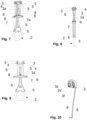
- FIGS. 1 to 12c illustrate various embodiments of a cam locking device also known as a "cam lock".
- the cam locking device is an active locking device.
- the cam locking device comprises a first end which is provided with a head 1 and a second opposite end which is an annular end 2.
- the head 1 is coupled to at least one cam 3 and preferably to several cams 3 which are mounted to pivot between an extended position and a retracted position. The space requirement in the extended position is greater than the space requirement in the retracted position.
- the cam(s) 3 are mounted to move about at least one pivot shaft 4.
- the cam(s) 3 are mechanically coupled to the head 1 so as to provide mechanical continuity between the cams 3 and the annular end 2.
- the pivot shaft 4 is fixed to the head 1. More precisely the pivot shaft 4 is fixed to a body 1a of the head 1.
- the body 1a can be formed by one or more parts.
- the cam locking device has two pivot shafts 4, preferably parallel.
- cam 3 defines an orifice 3Y intended to accommodate the pivot shaft 4 so that the cam pivots around the pivot shaft 4.
- the annular end 2 is in the form of a ring which defines a through hole configured to receive a carabiner.
- the annular end 2 is capable of supporting the weight of a user.
- the ring defines a through hole configured to receive a portion of the hand during the actuation phases of the cams 3.
- the cam locking device has a wire element 5 which mechanically connects the head 1 to the annular end 2.
- the wire element 5 mechanically couples the cams 3 to the annular end 2 so that a user attached to the annular end 2 is retained by means of the cams 3 wedged for example in a crack.
- the wire element 5 is the element which ensures the mechanical continuity between the head 1 and the annular end 2.
- the wire element 5 is fixed to the head 1 so as to mechanically couple the wire element 5 and the head 1.
- the wire element 5 extends in a first direction XX so as to achieve mechanical strength in this first direction XX.
- the pivot shaft 4 extends mainly in a second direction YY which is perpendicular or substantially perpendicular to the first direction XX.
- the wire element 5 is fixed to the head 1 and it extends continuously from the head 1 until it reaches the annular end 2 to achieve mechanical continuity along the locking device.
- the wire element 5 may be in the form of a ring, preferably a ring made of textile material.
- the wire element 5 may be a strap or a rope.
- the ring made of textile material may be a ring made of polyethylene with a very high molecular weight, for example in a material marketed under the names Dyneema or Spectra.
- a metal wire element, for example a cable, may also be used.
- the head 1 is provided with an anchor, preferably an anchor in the form of a shaft.
- the wire element 5 goes around the anchor in order to fix the wire element 5 with the anchor so as to allow the force to be taken up with the annular end 2.
- the wire element 5 defines at least one loop and the anchor shaft passes through the loop to carry out the force take up.
- the ring is advantageous for the ring to be obtained by sewing the two ends of the wire element 5 onto each other, the wire element 5 being a textile. Sewing is a well-controlled process which makes it easier to obtain a ring whose mechanical strength is controlled. The use of a sewing step makes it possible to form a ring which is less expensive and whose dimension is better controlled than its equivalent obtained by splicing. It is advantageous for the ring to be free of crimping and splicing.
- the locking device comprises an actuation system coupled to the at least one cam 3.
- the actuation system is configured to selectively engage the retracted position of the at least one cam 3.
- the actuation system has a trigger 7 slidably mounted along a first direction XX connecting the head 1 and the annular end 2.
- the trigger 7 is slidably mounted along the wire element 5 and along the rod 6 if applicable. The trigger 7 moves relative to the head 1 and the annular end 2.
- the trigger 7 is movable between a first trigger position and a second trigger position.
- the cam(s) 3 In the first trigger position, the cam(s) 3 may be in the extended position.
- the cam(s) 3 In the second trigger position, the cam(s) 3 are in the retracted position. Out of the first trigger position, the cam(s) 3 are out of the extended position.
- a movement of the trigger 7 in the direction of the head 1 does not impose any movement of the cam 3 and in particular does not translate into a movement of the cam 3 towards the extended position.
- the trigger 7 has anchoring holes 7a which are intended for the passage of the textile wire element 8 through the trigger 7.
- the textile wire element 8 extends from the trigger 7 to one of the cams 3.
- the first and second opposite ends of the textile wire element 8 are fixedly mounted to one of the cams 3 and the textile wire element 8 is fixed to the trigger 7 so that the movement of the trigger 7 towards the annular end 2 causes the pivoting of the cams 3 towards the retracted position.
- the spring 9 biases the trigger 7 toward the first trigger position.
- the spring 9 is configured so that the extended position and the first trigger position are rest positions of the locking device, i.e. in the absence of external bias.
- the cam locking device comprises at least one rod 6 which extends from the head 1 towards the annular end 2, i.e. in the first direction XX.
- the cam locking device comprises a single rod 6 which extends longitudinally in the first direction XX in abutment against the head 1 and which defines the through hole of the annular end 2.
- the third through hole 3c is arranged in the angular sector delimited by the straight line connecting the pivot axis of the cam 3 and the center of the first hole 3a and by the straight line connecting the pivot axis of the cam 3 and the center of the second hole 3b.
- the observation is made along the pivot axis of the cam 3 as illustrated in Figures 5a, 5c , 11a and 11c .
- center of the first hole 3a and center of the second hole 3b is meant the center of the circle when the hole is circular or the barycenter of the shape defined by the hole.
- the textile wire element 8 has a portion which is directed in the opposite direction to the direction taken by a previous portion along the longitudinal direction of the textile wire element 8. The direction of the direction is observed along the textile wire element 8 from the trigger 7 to the termination of the textile wire element 8.
- the first through hole 3a, the second through hole 3b and the third through hole 3c are aligned.
- the first strand 8a and the second strand 8b seek to move in different directions. This arrangement of the two strands tends to make the movement of the first strand 8a and the second strand 8b more complicated.
- the cam 3 may define a groove 3d on one of these sides.
- the groove 3d is arranged after the first hole 3a and after the second hole 3b, along the longitudinal direction of the textile wire element 8 from the trigger 7.
- the groove 3d makes it possible to wedge a portion of the textile wire element 8, preferably the terminal portion of the textile wire element 8.
- the groove 3d allows a greater or lesser quantity of textile wire element 8 to be wedged, which allows the effective length of the textile wire element 8 to be adjusted.
- the textile wire element 8 passes successively through the first hole 3a and the second hole 3b in the longitudinal direction of the textile wire element 8 from the trigger 7 before getting stuck in the groove 3d and/or passing into the third hole 3c.
- the successive passages of the textile wire element 8 through the multiple holes introduce changes in direction of the textile wire element 8 and therefore friction between the textile wire element 8 and the cam 3.
- the textile wire element 8 bears at each of the ends of the first hole 3a, the second hole 3b and the third hole 3c where appropriate. Each bearing generates friction which makes it more complicated for the textile wire element 8 to slide relative to the cam 3.
- At least one of the first hole 3a, the second hole 3b and the third hole 3c defines a sharp edge with the wall which defines the first side or the second side of the cam 3.
- the angle between the side wall of the hole and the side wall is between 75° and 105°, more preferably equal to 90°.
- the inventors have observed that the stress applied by the trigger 7 to the textile wire element 8 in association with the pivoting of the cam 3 has the effect of degrading the textile wire element 8 in the friction zone. Such behavior is not observed for the other support points for which the displacements are much smaller.
- By introducing a greater number of edges and preferably a rounded portion it is possible to improve the service life of the textile wire element 8, which allows for a greater choice in the accessible materials and in the usable sections. This makes it possible in particular to reduce the section of the textile wire element 8, which is preferable for small locking devices as it allows for reduced cross-sections of holes, grooves, and thinning areas.
- the section of the textile wire element 8 is less than the section of the first hole 3a and the second hole 3b from one end to the other of the textile wire element 8 in the longitudinal direction of the textile wire element 8.
- the section is observed in the absence of any stress, in particular longitudinal tensile stress of the textile wire element 8 so as to allow easy installation by an individual.
- the cam locking device has at least two cams 3.
- a first cam 3' and a second cam 3" are pivotally mounted and the textile wire element 8 has a first end fixed to a first cam 3' and a second opposite end fixed to the second cam 3".
- the two cams define the holes and/or grooves as described above. Each of the two ends is fixed according to one of the embodiments which have been presented previously.
- the textile wire element 8 is provided on the one hand and the cam locking device as presented according to any one of the preceding configurations on the other hand.
- the textile wire element 8 is connected to the trigger 7 and the terminal end of the strand of textile wire element 8 is introduced into the first hole 3a, then into the second hole 3b.
- the terminal end of the strand then passes through the third hole 3c or through the groove 3d.
- the terminal end of the strand then passes through the third hole 3c and is then embedded in the groove 3d.
- one end of the textile wire element 8 is fixed to a first cam 3' before fixing the other end according to the method described above.
Landscapes
- Engineering & Computer Science (AREA)
- General Engineering & Computer Science (AREA)
- Health & Medical Sciences (AREA)
- Mechanical Engineering (AREA)
- Pulmonology (AREA)
- General Health & Medical Sciences (AREA)
- Physical Education & Sports Medicine (AREA)
- Purses, Travelling Bags, Baskets, Or Suitcases (AREA)
- Preliminary Treatment Of Fibers (AREA)
- Sewing Machines And Sewing (AREA)
Applications Claiming Priority (1)
| Application Number | Priority Date | Filing Date | Title |
|---|---|---|---|
| FR2311066A FR3154159B1 (fr) | 2023-10-13 | 2023-10-13 | Dispositif de blocage à came mobile et procédé de fabrication d’un dispositif de blocage à came mobile |
Publications (1)
| Publication Number | Publication Date |
|---|---|
| EP4538544A1 true EP4538544A1 (de) | 2025-04-16 |
Family
ID=89308585
Family Applications (1)
| Application Number | Title | Priority Date | Filing Date |
|---|---|---|---|
| EP24204866.8A Pending EP4538544A1 (de) | 2023-10-13 | 2024-10-06 | Blockiervorrichtung mit beweglichem nocken und verfahren zur herstellung einer verriegelungsvorrichtung mit beweglichem nocken |
Country Status (4)
| Country | Link |
|---|---|
| US (1) | US20250121253A1 (de) |
| EP (1) | EP4538544A1 (de) |
| CN (1) | CN223980060U (de) |
| FR (1) | FR3154159B1 (de) |
Citations (2)
| Publication number | Priority date | Publication date | Assignee | Title |
|---|---|---|---|---|
| DE3545306C1 (en) * | 1985-12-20 | 1987-06-04 | Steinacker Paul Heinrich | Climbing apparatus |
| US20090152421A1 (en) * | 2003-08-12 | 2009-06-18 | Metolius Mountain Products, Inc. | Mechanical Climbing Aid of the Cam Type |
-
2023
- 2023-10-13 FR FR2311066A patent/FR3154159B1/fr active Active
-
2024
- 2024-10-06 EP EP24204866.8A patent/EP4538544A1/de active Pending
- 2024-10-12 CN CN202422467063.XU patent/CN223980060U/zh active Active
- 2024-10-15 US US18/916,150 patent/US20250121253A1/en active Pending
Patent Citations (2)
| Publication number | Priority date | Publication date | Assignee | Title |
|---|---|---|---|---|
| DE3545306C1 (en) * | 1985-12-20 | 1987-06-04 | Steinacker Paul Heinrich | Climbing apparatus |
| US20090152421A1 (en) * | 2003-08-12 | 2009-06-18 | Metolius Mountain Products, Inc. | Mechanical Climbing Aid of the Cam Type |
Also Published As
| Publication number | Publication date |
|---|---|
| CN223980060U (zh) | 2026-03-10 |
| FR3154159B1 (fr) | 2025-10-17 |
| US20250121253A1 (en) | 2025-04-17 |
| FR3154159A1 (fr) | 2025-04-18 |
Similar Documents
| Publication | Publication Date | Title |
|---|---|---|
| EP0008560B1 (de) | Vorsegelroller mit Reffeinrichtung | |
| EP3599000A1 (de) | Abseilgerät mit seilrolle | |
| FR2649284A1 (fr) | Tete de coupe, pouvant etre entrainee en rotation, pour un appareil a couper des plantes | |
| EP3071856B1 (de) | Elastischen befestigungselement eines dicken bremsseilendes | |
| EP3659675A2 (de) | Sicherungsvorrichtung | |
| EP4538544A1 (de) | Blockiervorrichtung mit beweglichem nocken und verfahren zur herstellung einer verriegelungsvorrichtung mit beweglichem nocken | |
| EP3747518B1 (de) | Doppelte riemenscheibe | |
| FR3068686A1 (fr) | Dispositif d'enroulement d'un tube souple | |
| EP3563067B1 (de) | Bändelungsvorrichtung | |
| FR2765249A1 (fr) | Procede pour poser une gaine en forme de tube sur une membrure tendue et dispositif pour ecarter une gaine en forme de tube | |
| EP4066906B1 (de) | Vorrichtung zur befestigung an einen verankerungspunkt und verfahren zur anwendung einer solchen befestigungsvorrichtung | |
| EP1900073A1 (de) | Zange zum ablösen von röhrenförmigen elementen insbesondere von kabeln oder ähnlichem | |
| EP3924070B1 (de) | Verbinder, lösbare gabelattrappe mit einem solchen verbinder und betriebsverfahren | |
| EP4389244B1 (de) | Nockenverriegelungsvorrichtung und verfahren zum verstellen eines drahtelements einer nockenverriegelungsvorrichtung | |
| EP4389243A1 (de) | Nockenverriegelungsvorrichtung, verfahren zur herstellung einer solchen vorrichtung und verfahren zum ersetzen eines drahtelements einer solchen vorrichtung | |
| EP4028714B1 (de) | Maschine zum abschiessen von zielscheiben beim tontaubenschiessen | |
| EP3026767B1 (de) | Verankerungsverfahren zum verankern eines kabels mit einem bestimmten durchmesser in einer halterung | |
| WO2018115787A1 (fr) | Methode et installation de reglage du pas des spires d'une carcasse metallique | |
| EP4389242A1 (de) | Nockenverriegelungsvorrichtung und verfahren zur herstellung solch einer vorrichtung und verfahren zum ersetzen eines drahtelements einer solchen vorrichtung | |
| FR3144017A1 (fr) | Dispositif de blocage à came mobile et procédé de fixation d’un dispositif de blocage à came mobile à un élément filaire | |
| FR3052479B1 (fr) | Fenetre comprenant un dispositif de mouflage | |
| EP4034272B1 (de) | Riemenscheibe mit bewegung in eine richtung | |
| FR3144018A1 (fr) | Dispositif de blocage à came, harnais comportant un dispositif de blocage à came et procédé de fixation/désolidarisation d’un tel dispositif de blocage à came avec un support | |
| FR2631420A1 (en) | Variable-diameter pulley for variable speed drive - has belt bearing segments engaged in flanges with leaf spring and pin fixing | |
| EP4311449A1 (de) | Gurtverstellsystem |
Legal Events
| Date | Code | Title | Description |
|---|---|---|---|
| PUAI | Public reference made under article 153(3) epc to a published international application that has entered the european phase |
Free format text: ORIGINAL CODE: 0009012 |
|
| STAA | Information on the status of an ep patent application or granted ep patent |
Free format text: STATUS: THE APPLICATION HAS BEEN PUBLISHED |
|
| AK | Designated contracting states |
Kind code of ref document: A1 Designated state(s): AL AT BE BG CH CY CZ DE DK EE ES FI FR GB GR HR HU IE IS IT LI LT LU LV MC ME MK MT NL NO PL PT RO RS SE SI SK SM TR |
|
| STAA | Information on the status of an ep patent application or granted ep patent |
Free format text: STATUS: REQUEST FOR EXAMINATION WAS MADE |
|
| 17P | Request for examination filed |
Effective date: 20251007 |
|
| GRAP | Despatch of communication of intention to grant a patent |
Free format text: ORIGINAL CODE: EPIDOSNIGR1 |
|
| STAA | Information on the status of an ep patent application or granted ep patent |
Free format text: STATUS: GRANT OF PATENT IS INTENDED |
|
| RIC1 | Information provided on ipc code assigned before grant |
Ipc: F16B 2/04 20060101AFI20260108BHEP Ipc: A63B 29/02 20060101ALI20260108BHEP |
|
| GRAJ | Information related to disapproval of communication of intention to grant by the applicant or resumption of examination proceedings by the epo deleted |
Free format text: ORIGINAL CODE: EPIDOSDIGR1 |
|
| STAA | Information on the status of an ep patent application or granted ep patent |
Free format text: STATUS: REQUEST FOR EXAMINATION WAS MADE |
|
| INTG | Intention to grant announced |
Effective date: 20260121 |
|
| GRAP | Despatch of communication of intention to grant a patent |
Free format text: ORIGINAL CODE: EPIDOSNIGR1 |
|
| STAA | Information on the status of an ep patent application or granted ep patent |
Free format text: STATUS: GRANT OF PATENT IS INTENDED |
|
| INTC | Intention to grant announced (deleted) |